32
SENSORS AND SAFETY PRODUCT LINEUP SENSORS SAFETY PROCESS
SENSORS AND SAFETY
PRODUCT LINEUP
SENSORS SAFETY
PROCESS

Since 1974, KEYENCE has
steadily grown and innovated to
become a world leader in the
development of automation and
quality assurance solutions
KEYENCE VALUE
Customer
Quick Response!
Direct Request
Local
Specialized Product Expert
KEYENCE Direct
Your Sales Engineer
Direct Sales Network
USA
Same-Day Shipping
Chicago
Products ordered by 4:00 PM CST are shipped from
our warehouse center in Chicago the same day!
Comprehensive Support
Selection Implementation After-SalesSupport
All From KEYENCE
On-Site Product Demonstrations
Application Sample Testing
Direct Phone & On-Site Support
Direct Support
2

Global Network
200
Offices
45
Countries
200,000+ Clients
Over
in more than
Around the World
Innovative Technology
Products featuring World’s First or Industry’s First Technology
70 %NEW
2011 to 2017The World’s Most InnovativeCompanies Top 100 – Forbes
Corporate Information
Note: US dollar amounts are converted from Japanese yen for convenience only at ¥113 = US$1, the approximate exchange rate on March 20, 2017.
Global Headquarters: Osaka, JapanFounded: May 1974Capital: $271,128,000 USD2016 Global Sales: $3,652,211,000 USDWorldwide Employees: 5,670
3

LR-Z Series≥ Unmatched Stability
≥ Rugged Stainless Steel Housing
≥ Simplified Operation and Setup
LR-T Series≥ Long Range Stable Detection
≥ All-in-One Design and Functionality
≥ Innovative OLED Display
LR-W Series≥ White LED for Full Spectrum Detection
≥ Long Range, Dual Spot, and Fiber Models
≥ Controller Expansion for Increased Functionality
Standard Photoeyes
PZ Series
P16 to 17
Robust Photoeyes
PR Series
P14 to 15
Fiber Optic Sensors
FS/FU Series
P10 to 11
All-Purpose Sensors P6
Long Distance Presence Sensors P7
Appearance Sensors P8
Additional Sensors
Specialty Sensors
LV/PX/GV/CZ Series
P12 to 13
4

GL-R Series≥ Built-in Guarding
≥ Full-Length Protection
≥ Innovative Wiring Options
SZ-V Series≥ Industry Leading
Range
≥ Easy to Use Software
≥ Built-in Camera
Safety Light Curtains P18
Safety Laser Scanners P21
Process Sensors
Additional Products
Proximity Sensors
EV/EZ/ED/EM/ ES/ET/TA Series
Pressure Sensors
GP/AP SeriesGuide Pulse Level Sensors
FL Series
P23 to 24 P25 to 26
P27 to 29 P30 P30
Power Supplies
MS SeriesControl Units
CU Series
Clamp-On Flow Meters
FD-R/Q Series≥ 1/4" to 8" Pipes
≥ No Pipe Modification
≥ Detects Any Liquid ≥ Completely Trouble‐Free
≥ Range up to 2m (6.6')
≥ Detects Any Liquid
P22 to 23
5

LR-Z SeriesCMOS Laser Sensors
Key Fe ature s
≥ Stably and reliably detect any target
≥ Simplified 1-pt calibrations
≥ Robust IP68/IP69K enclosure ratings
Sensors
Approx. ø3 mm ø0.12"
Approx. ø3 mm ø0.12"
Approx. 1 mm 0.04"
Approx. 1 mm 0.04"
Approx. 1.2 mm 0.05"
Approx. 1.2 mm 0.05"
Approx. 2 mm 0.08"
Approx. 2 mm 0.08"
Approx. 2.4 mm 0.09"
Approx. 2.4 mm 0.09"
Type Detecting distance Spot diameter Connection method Output Model
M18 threaded mount w/ M12 connector 25 to 490 mm 0.98" to 19.29"
M12 4-pin NPN/PNP selectable
LR-ZH490CB U.C.D. Function
M18 threaded mount w/ M12 connector 25 to 240 mm 0.98" to 9.45"
At detecting distance of 240 mm 9.45"
M12 4-pin
Bipolar(NPN+ PNP)
LR-ZB240CB
M18 threaded mount w/ M12 connector 25 to 90 mm 0.98" to 3.54"
At detecting distance of 90 mm 3.54"
M12 4-pin LR-ZB90CB
Rectangular w/ cable
35 to 500 mm 1.38" to 19.69"
2 m cable
NPN LR-ZH500N U.C.D. Function
PNP LR-ZH500P U.C.D. Function
Rectangular w/ M8 connector
M8 4-pin
NPN LR-ZH500CN U.C.D. Function
PNP
LR-ZH500CP U.C.D. Function
M8 3-pin LR-ZH500C3P U.C.D. Function
Rectangular w/ cable
35 to 250 mm 1.38" to 9.84"
At detecting distance of 250 mm 9.84"
2 m cable
NPN LR-ZB250AN
PNP LR-ZB250AP
Rectangular w/ M8 connector
M8 4-pinNPN LR-ZB250CN
PNPLR-ZB250CP
M8 3-pin LR-ZB250C3P
Rectangular w/ cable
35 to 100 mm 1.38" to 3.94"
At detecting distance of 100 mm 3.94"
2 m cable
NPN LR-ZB100N
PNP LR-ZB100P
Rectangular w/ M8 connector
M8 4-pinNPN LR-ZB100CN
PNPLR-ZB100CP
M8 3-pin LR-ZB100C3P
* When using the reflector or reflective tape, ensure that the spot from the sensor is stationary on the reflector.
Type Model Compatible models Maximum detecting distance Appearance
Reflector R-6L
LR-ZH models
700 mm 27.56"
Reflective tape OP-87123 700 mm 27.56"
25 × 25 mm 0.98" × 0.98"
Reflectors (For U.C.D. function only)
Type Model Compatible models Material/Weight
Standard mounting bracket (M3 screw × 2 supplied)
OP-87408*1 Rectangular SUS316L 30 g
Rear mounting bracket (M3 screw × 2 supplied) OP-87409 Rectangular SUS316L
30 g
Robust mounting bracket (t = 3) (M3 screw × 2 supplied)
OP-87410*2 Rectangular SUS316L 170 g
M18 nut & Lock washer set OP-87413 M18
Threaded MountM18 nut SUS316L 10 g
Lock washer SUS304 5 g
Type Model Compatible models Material/Weight
Adjustable bracket (M3 screw × 2 supplied) OP-87404 Rectangular Zinc nickel plating
95 g
Adjustable bracket OP-87405 M18 Threaded Mount
Zinc nickel plating 100 g
Locking screw for adjustable bracket
Screw length: 45 mm 1.77" OP-87406 — Iron nickel plating
70 g
Screw length: 65 mm 2.56" OP-87407 — Iron nickel plating
80 g
Adjustable bracket for threaded mount type
Adjustable bracket for rectangular type
Brackets
Adjustable bracket
*1 This bracket is dedicated to the cable type. Use OP-87409 or OP-87410, when installing the connector type. *2 This can be used only in combination with an L-shaped connector cable, when installing the connector type.
Screw length
LR-Z
LR-T
FS/F
ULV
PX/G
V/CZ
PR-G
PR-M
/FPZ
-GPZ
-V/M
LR-W
MU
-N
6
LR-Z

LR-T SeriesTOF Laser Sensors
Key Fe ature s
≥ Position based sensing ignores color changes
≥ Max 5 m (16.4') range
≥ Intuitive OLED display
SensorsType Detecting distance Features Model
Cable (2 m 6.6')
60 to 5000 mm 2.36" to 196.85"
Adjustable SpotAnatog Output
LR-TB5000
M12 connector(Cable sold separately)
LR-TB5000C LR-TB5000CL
Cable(2 m 6.6')
60 to 2000 mm 2.36" to 78.74"Smaller Size
LR-TB2000
M12 connector(Cable sold separately)
LR-TB2000C LR-TB2000CL
Type Model Material/Weight
Adjustable angle bracket(For LR-TB5000 Series)(M4 screw × 2 supplied)
OP-87773SUS304
Approx. 150 g
Adjustable angle bracket(For LR-TB2000 Series)(M3 screw × 2 supplied)
OP-87771SUS304
Approx. 110 g
Small bracket(For LR-TB2000 Series)(M3 screw × 2 supplied)
OP-87770SUS304
Approx. 80 g
Type Model Material/Weight
Front protection cover(For LR-TB5000 Series)
OP-87778SUS304, PC,
etc. Approx. 6 g
Front protection cover(For LR-TB2000 Series)
OP-87776SUS304, SUS430, PC,
etc. Approx. 50 g
Type Model Material/Weight
Adjustable bracket (For LR-TB5000 Series)(M4 screw × 2 supplied)
OP-87774Zinc nickel plating,
etc. Approx. 120 g
Adjustable bracket (For LR-TB2000 Series)(M3 screw × 2 supplied)
OP-87772Zinc nickel plating,
etc. Approx. 110 g
Locking screw (For adjustable bracket)(85 mm 3.35")
OP-87775Iron nickel plating
Approx. 120 g
M12
Brackets
Protection covers
LR-TB5000 + OP-87774 + OP-87775 LR-TB2000 + OP-87772 + OP-87775
LR-Z
LR-T
FS/FUPX/GV/CZ
PR-G
PR-M
/FPZ-G
PZ-V/MLR
-WM
U-N
LV
7
LR-T

LR-W SeriesFull-Spectrum Sensors
Key Fe ature s
≥ Detect any changes in appearance
≥ Metal housing with IP67 enclosure rating
≥ Innovative white LED
Sensors: Standard ModelsType Detecting distance Light source Model
Cable(2 m 6.6')
Standard Type
30 to 500 mm 1.18" to 19.69"
White LED
LR-W500
M12 connector(Cable sold separately)
LR-W500C
Sensors: Small/Dual Spot ModelsType Detecting distance Light source Model
Cable(2 m 6.6')
Small /DualSpot Type
30 to 70 mm 1.18" to 2.76"
White LED
LR-W70
M12 connector(Cable sold separately)
LR-W70C
Sensors: Fiber Extension ModelsType Detecting distance Light source Model
Cable(2 m 6.6')
Fiber Type
Detecting distance and min. spot
diameter are based on the attached
fiber head
White LED
LR-WF10
M12 connector(Cable sold separately)
LR-WF10C
Feature / Type Fiber unit length (Diameter)Ambient temperature Appearance Detecting distance Model
M3 Hex-shaped Coaxial
1 m 3.3' Free-cut (ø1.3 ø0.05" × 2)
-40 to +50°C -40 to +122°F
500 ms: 47 1.85"100 ms: 32 1.26"10 ms: 12 0.47"1 ms: 7 0.28"
250 μs: 5 0.20"
FU-35TZ
M3 Threaded Coaxial
1 m 3.3' Free-cut (ø1.3 ø0.05" × 2)
-40 to +50°C -40 to +122°F
FU-35FZ
Cylinder (Set Screw Installation)
Diameter ø2 ø0.08"
1 m 3.3' Free-cut ø1.0 ø0.04" × 2
-40 to +50°C -40 to +122°F
500 ms: 33 1.30"100 ms: 24 0.94"10 ms: 9 0.35"1 ms: 4 0.16"
250 μs: 3 0.12"
FU-49U
Beam spot diameterø0.9 to 3.5 ø0.04" to
ø0.14"Focal distance
10 to 30 0.39" to 1.18"
2 m 6.6' Free-cut (ø1.3 ø0.05" × 2)
-40 to +70°C-40 to +158°F
10 to 300.39" to 1.18"
FU-10
Beam spot diameterApprox. ø0.1 ø0.004”
Focal distance5 0.20”
50 cm 1.6' Cut not allowed-40 to +70°C -40 to +158°F
5 ± 10.20" ± 0.04"
FU-20
Feature / Type Fiber unit length (Diameter)Ambient temperature Appearance Detecting distance Model
Focused Beam / High-power
Aperture angle: Approx. 8°
2 m 6.6' Free-cut (ø2.2 ø0.09" × 2)
-40 to +50°C -40 to +122°F
500 ms: 26 to 379 1.02" to 14.92"100 ms: 27 to 270 1.06" to 10.63"10 ms: 33 to 112 1.30" to 4.41"
1 ms: — 250 μs: —
FU-40
Definite-reflective
Thin, Small
2 m 6.6' Free-cut (ø2.2 ø0.09" × 2)
-40 to +70°C-40 to +158°F
500 ms: 2 to 131 0.08" to 5.16"100 ms: 3 to 119 0.12" to 4.69"10 ms: 10 to 93 0.39" to 3.66"1 ms: 12 to 79 0.47" to 3.11"
250 μs: 13 to 68 0.51" to 2.68"
FU-40S
Sleeve
Side view detection
2 m 6.6' Free-cut (ø1.0 ø0.04" × 2)
-40 to +70°C -40 to +158°F
500 ms: 30 1.18"100 ms: 20 0.79"10 ms: 7 0.28"1 ms: 3 0.12"
250 μs: 2 0.08"
FU-31
Heat Resistant
Heat resistant temperature*2: 300ºC 572˚F
1 m 3.3' Cut not allowed-40 to +300°C -40 to +572°F
500 ms: 158 6.22"100 ms: 107 4.21"10 ms: 40 1.57"1 ms: 24 0.94"
250 μs: 16 0.63"
FU-83C
17 0.67"
190.75"
7.4 0.29"
21 0.83"
Thickness: 5.2 0.20"
ø0.08" ø2
Do not bend sleeve.
ø0.11" ø2.8
150.59" 15
0.59"
17 0.67"
10 0.39"
ø0.10" ø2.6
M4
M3
0.73" 18.5
M3
0.67" 17
ø2 ø0.08"
0.39" 10
M6
26.4 to 31.51.04" to 1.24"
18 0.71"
Tip: ø3 ø0.12"
Applicable Fiber Heads
LR-Z
LR-T
FS/F
ULV
PX/G
V/CZ
PR-G
PR-M
/FPZ
-GPZ
-V/M
LR-W
MU
-N
8
LR-W

Type Applicable Sensors ModelStandardmounting bracket(M3 screw × 2 supplied)
LR-W500/W70/WF10
OP-88021*1
Smallmounting bracket(M3 screw × 2 supplied)
LR-W70/WF10
OP-88022*1
Adjustable bracket(M3 screw × 2 supplied) LR-W500(C)/
W70(C)/WF10(C)
OP-88023
Adjustable bracketlocking screw (105 mm 4.13")
OP-88024
LR-W SeriesFull-Spectrum Sensors
MU-N SeriesMulti-Sensor Controllers
Key Fe ature s
≥ Detect any changes in appearance
≥ Metal housing with IP67 enclosure rating
≥ Innovative white LED
Key Fe ature s
≥ Compatible with LR-W, LR-T, and FD-Q Series
≥ Increases sensor functionality and provide seperate controller
≥ Dual 7-Segment and OLED displays
Type Beam spotdiameter Focal distance
Lens Fiber unitsModel Appearance Weight Model
Small spot
Approx. ø0.4ø0.02"
7 ±20.28" ±0.08"
F-2HA-30 to +70°C -22 to +158°F
FU-35FZ
FU-35TZ
Approx. ø0.5ø0.02"
15 ±20.59" ±0.08"
F-4HA-30 to +70°C -22 to +158°F
FU-35FZ
FU-35TZ
Side-viewadjustable
spot
Approx. ø0.5 to ø3ø0.02" to ø0.12"
8 to 300.32" to 1.18"
F-5HA-30 to +70°C -22 to +158°F FU-35FZ
Tip: ø7.4 ø0.29"
Approx. 2 g
27 1.06"
15.6 0.61"
Tip: ø4.3 ø0.17"
Approx. 1 g
8.7 0.34"
5.6 0.22"
15 0.59" Approx. 2 g
Applicable Fiber Lenses
Brackets and AccessoriesType Applicable Sensors Model
Lustercancelingattachment
LR-W500(C) LR-WA1*1*2
Luster canceling attachment LR-W70(C) LR-WA2*1*2
*1 When using LR-WA1 or LR-WA2, detecting range may decrease on targets with low reflectance. Perform sufficient checks in the actual installation environment.
*2 When using the LR-WA1 or LR-WA2, the enclosure rating (IP65/IP67) is not met.
*1 The 4-pin M12 connector type may not be mounted in the orientation shown in the picture (connector downward). Confirm the dimensions and surroundings carefully.
Cables (MU-N Power Cable)Appearance Applicable unit Cable material Cable end Controller side Length Model
Main unit
PVC (Polyvinyl chloride)
8-core loose wires
Connector
2 m 6.6'
MU-CB84-core loose wires MU-CB4
Expansion unit 6-core loose wires MU-CB62-core loose wires MU-CB2
Main unitM12 4-pin
straight0.3 m 1.0' MU-CC4
ConnectorsAppearance Type Applicable model Model
For PVC (Polyvinyl chloride) cableNon-connector type LR-W, LR-T, and FD-Q Series sensorsOP-75721/87272/85502OP-75722/87273/87274
OP-88029
For PUR (Polyurethane) cableOP-87636/87637OP-87640/87641
OP-88030
Cables (Sensor to Controller Cable)Appearance Cable material Sensor side Controller side Length Model
PVC (Polyvinyl chloride)
M12 4-pin straight
Connector
2 m 6.6' OP-88025
10 m 32.8' OP-88026*1
M12 4-pin L-shape
2 m 6.6' OP-88027
10 m 32.8' OP-88028*1
*1 The 10 m 32.8' cable includes one spare connector for the controller side.
Controllers Type Control output External input Analog output Model
Main unit 4 standard outputs max.*(15 signal combinations
available using binary logic)5 inputs max.*
1 output max.* MU-N11
Expansion unit — MU-N12
*The number of control outputs and external inputs available is based on the sensor type connected and internal settings. Contact Keyence for more information.
LR-Z
LR-T
FS/FUPX/GV/CZ
PR-G
PR-M
/FPZ-G
PZ-V/MLR
-WM
U-N
LV
9
LR-W
MU
-N

FS / FU SeriesDigital Fiber Sensors
Key Fe ature s
≥ Selection from 150 fiber heads
≥ High powered detection
≥ Easy to read OLED display
TypeModel
Control outputs External inputNPN output PNP output
Main unit
Expansion unit
StandardMain unit FS-N41N FS-N41P
1 0Expansion unit FS-N42N FS-N42P
2-OutputMain unit FS-N43N FS-N43P
2 1Expansion unit FS-N44N FS-N44P
TypeModel
Control outputs External inputSwitchable between NPN/PNP output
Main unit FS-N41C 2* 1*
* Switchable between 2 control outputs, or 1 control output + 1 external input.
TypeModel Separate control
outputs Control outputs External inputNPN output PNP output
Compatible with all NEO Series Expansion Units Main unit FS-MC8N FS-MC8P 8 1 1
Type Model Control outputs
For use with Multi‐Output Unit or NU Series Network Expansion unit FS-N40 None*
* Counted as 1 output if expanded with Multi-Output Unit FS-MC8N/P or the NU Series communication unit.
Cable Type
M8 Connector Type
Multi-Output Unit
Zero-Line Type
Reflective ReflectiveGuarded Fibers
Thrubeams
Amplifiers
Type
Appearance(mm inch)
Fiber unit length (Diameter)
Ambient temperature
Minimum bend radius(mm inch)
Detecting distance (mm inch)*1
ModelWeightSize / Shape TERA (Longest)
FINE (Initial)
Other power modesMEGAULTRASUPER
TURBO HSPD
S-HSPD
M6
Hex-shaped
M6
16.8 0.66" 2 m 6.6' Free-cut(Ø2.2 ø0.09" × 2)−40 to +60˚C(-40 to +140°F)
R2R0.08"
ToughFlex790 31.10"
210 8.27"
710 27.95"550 21.65"470 18.50"
310 12.20"90 3.54"56 2.20"
FU-R67TZApprox. 25 g
M6
18 0.71" 1 m 3.3' Cut not allowed. −40 to +60˚C(-40 to +140°F)
R10R0.39"
Stainless Steel
790 31.10"
210 8.27"
710 27.95"550 21.65"470 18.50"
310 12.20"90 3.54"56 2.20"
FU-R67TGApprox. 32g
Threaded
M6
17 0.67" 2 m 6.6' Free-cut(Ø2.2 ø0.09" × 2)−40 to +60˚C(-40 to +140°F)
R2R0.08"
ToughFlex1100 43.31"
210 8.27"
900 35.43"740 29.13"490 19.29"
320 12.60"110 4.33"65 2.56"
FU-R67Approx. 21g
M6
17 0.67" 2 m 6.6' Free-cut(Ø2.2 ø0.09" × 2)−40 to +60˚C(-40 to +140°F)
R25R0.98"
1150 45.28"
300 11.81"
1100 43.31"860 33.86"570 22.44"
410 16.14"140 5.51"67 2.64"
FU-R6FApprox. 21g
M6
17 0.67" 1 m 3.3' Cut not allowed.−40 to +60˚C(-40 to +140°F)
R10R0.39"
Stainless Steel
1100 43.31"
210 8.27"
900 35.43"740 29.13"490 19.29"
320 12.60"110 4.33"65 2.56"
FU-R67GApprox. 29g
*1 When using the FS-N40 Series. Standard target: White matte paper (Reflective type only.)
ThrubeamsType
Appearance
(mm inch)
Fiber unit length (Diameter)Ambient
temperature
Minimum bend radius
(mm inch)
Detecting distance (mm inch)*1
Optical axis diameter
(mm inch)
ModelWeightSize / Shape TERA (Longest)
FINE (Initial)
Other power modesMEGAULTRASUPER
TURBO HSPD
S-HSPD
M4
Hex-shaped
M4
14.40.57"
16.9 0.67" 2 m 6.6' Free-cut(ø2.2 ø0.09")−40 to +60˚C(-40 to +140°F)
R2R0.08"
ToughFlex3600 141.73"
640 25.20"
3100 122.05"2100 82.68"1300 51.18"
880 34.65"320 12.60"190 7.48"
Transmitter:ø1
ø0.04"
Receiver:ø3.2
ø0.13"
FU-R77TZApprox. 25 g
M4
150.59"
17.5 0.69" 1 m 3.3' Cut not allowed.−40 to +60˚C(-40 to +140°F)
R10R0.39"
Stainless Steel
1800 70.87"
640 25.20"
1800 70.87"1800 70.87"1300 51.18"
880 34.65"320 12.60"190 7.48"
FU-R77TGApprox. 43 g
Threaded
M4 16.50.65"
14 0.55"
2 m 6.6' Free-cut(Ø2.2 ø0.09")−40 to +60˚C(-40 to +140°F)
R2R0.08"
ToughFlex3600 141.73"
880 34.65"
3600 141.73"3000 118.11" 1800 70.87"
1300 51.18"430 16.93"240 9.45"
FU-R77Approx. 21 g
M4 17.50.69"
15 0.59"
2 m 6.6' Free-cut(Ø2.2 ø0.09")−40 to +60˚C(-40 to +140°F)
R25R0.98"
3600 141.73"
1100 43.31"
3600 141.73"3200 125.98"2200 86.61"
1500 59.06"540 21.26"290 11.42"
FU-R7FApprox. 21 g
M4 24.50.96"
22 0.87"
1 m 3.3' Cut not allowed.−40 to +60˚C(-40 to +140°F)
R10R0.39"
Stainless Steel
1800 70.87"
880 34.65"
1800 70.87"1800 70.87"1800 70.87"
1300 51.18"430 16.93"240 9.45"
FU-R77GApprox. 41 g
* When using the FS-N40 Series. “3600 mm 141.73" (1800 mm 70.87")” is assumed as maximum because the fiber cable has a length of 2 m 6.6' (1 m 3.3').
Type
Appearance(mm inch)
Fiber unit length (Diameter)Ambient
temperature
Minimum bend radius(mm inch)
Detecting distance (mm inch)*1
ModelWeightSize / Shape Detecting
Arrangement TERA (Longest) FINE (Initial)
Other power modes
MEGAULTRASUPER
TURBO HSPD
S-HSPD
M3 Threaded Coaxial
18 0.71"
M3
1 m 3.3' Cut not allowed.−40 to +50°C(-40 to +122°F)
R10R0.39”
590 23.23"
130 5.12"
540 21.26"420 16.54"320 12.60"
190 7.48"47 1.85"28 1.10"
FU-2303Approx. 20 g
18 0.71”
M3
1 m 3.3' Free-cut(ø1.3 × 2)spiral 30 cm 11.81"−40 to +50˚C(-40 to +122°F)
R10R0.39”
Stainless Steel
590 23.23"
130 5.12"
540 21.26"420 16.54"320 12.60"
190 7.48"47 1.85"28 1.10"
FU-35FGApprox. 15 g
M6
Hex-shaped
ParallelM6
17 0.67” 1 m 3.3' Cut not allowed.−40 to +50˚C(-40 to +122°F)
900 35.43"
380 14.96"
830 32.68"730 28.74"670 26.38"
520 20.47"150 5.91"89 3.50"
FU-67TGApprox. 32 g
M6
20.5 0.81" 1 m 3.3' Cut not allowed.−40 to +50°C(-40 to +122°F)
R25R0.98”
Stainless Steel
900 35.43"
380 14.96"
830 32.68"730 28.74"670 26.38"
520 20.47"150 5.91"89 3.50"
FU-67MTGApprox. 80 g
CoaxialM6
22.5 0.89"1 m 3.3' Cut not allowed.−40 to +50˚C(-40 to +122°F)
R10R0.39”
Stainless Steel
580 22.83"
120 4.72"
530 20.87"390 15.35"250 9.84"
170 6.69"45 1.77"27 1.06"
FU-35TGApprox. 32 g
Threaded ParallelM6
29 1.14"1 m 3.3' Cut not allowed.−40 to +50˚C(-40 to +122°F)
R25R0.98”
Stainless Steel
1100 43.31"
380 14.96"
1000 39.37"830 32.68"610 24.02"
500 19.69"150 5.91"88 3.46"
FU-67MGApprox. 70 g
M6
17 0.67”1 m 3.3' Cut not allowed.−40 to +50˚C(-40 to +122°F)
R10R0.39”
Stainless Steel
1100 43.31"
380 14.96"
1000 39.37"830 32.68"610 24.02"
500 19.69"150 5.91"88 3.46"
FU-67GApprox. 29 g
*1 When using the FS-N40 Series. Standard target: White matte paper (Reflective type only.)
Type
Appearance(mm inch)
Fiber unit length (Diameter)Ambient
temperature
Minimum bend radius
(mm inch)
Detecting distance (mm inch)*1
Optical axis
diameter(mm inch)
ModelWeightSize / Shape TERA (Longest)
FINE (Initial)
Other power modes
MEGAULTRASUPER
TURBO HSPD
S-HSPD
M4
Hex-shaped
M415 0.59"
1 m 3.3' Cut not allowed.−40 to +50˚C(-40 to +122°F)
R10R0.39"
Stainless Steel
1800 70.87"
1100 43.31"
1800 70.87"1800 70.87"1800 70.87"
1400 55.12"430 16.93"280 11.02"
ø1.13ø0.04"
FU-77TGApprox. 43 g
M4
150.59" 1 m 3.3' Cut not
allowed.−40 to +50˚C(-40 to +122°F)
R20R0.79"
Stainless Steel
1800 70.87"
1100 43.31"
1800 70.87"1800 70.87"1800 70.87"
1400 55.12"430 16.93"280 11.02"
FU-77MTG
Approx. 100 g
Threaded
M4 220.87”
1 m 3.3' Cut not allowed.−40 to +50˚C(-40 to +122°F)
R10R0.39"
Stainless Steel
1800 70.87"
1100 43.31"
1800 70.87"1800 70.87"1800 70.87"
1400 55.12"430 16.93"280 11.02"
FU-77GApprox. 39 g
M427
1.06"
1 m 3.3' Cut not allowed.−40 to +50˚C(-40 to +122°F)
R20R0.79"
Stainless Steel
1800 70.87"
1100 43.31"
1800 70.87"1800 70.87"1800 70.87"
1400 55.12"430 16.93"280 11.02"
FU-77MGApprox. 100 g
*1 When using the FS-N40 Series. “3600 mm 141.73" (1800 mm 70.87")” is assumed as maximum because the fiber cable has a length of 2 m 6.6' (1 m 3.3').
Fiber HeadsActive Receiver Fibers
LR-Z
LR-T
FS/F
ULV
PX/G
V/CZ
PR-G
PR-M
/FPZ
-GPZ
-V/M
LR-W
MU
-N
10
FS/F
U

TypeFiber unit length (Diameter)
Ambient temperatureAppearance Minimum bend
radius
Detecting distanceSmallest detectable
objectModel
Weight TERA (Longest) FINE (Initial)
Definite Reflective
R2R0.08"
ToughFlex30 to 2700 1.18" to 10.63"
30 to 530 1.18" to 20.87"
ø0.3 ø0.01"copper wire
(vertical)FU-40
Approx. 23 g
Definite Reflective
R25R0.98"
15 to 150 0.59" to 5.91"
15 to 55 0.59" to 2.17"
— FU-40SApprox. 25 g
Sleeve R10R0.39"
340 13.39"
59 2.30"
ø0.005ø0.0002"gold-wire
FU-31Approx. 5 g
Tough FlexR2
R0.08"ToughFlexHigh-flex
290 11.42"
59 2.30"
ø0.005ø0.0002"gold-wire
FU-49UApprox. 4 g
High Temperature
R25R0.98"
790 31.10"
350 13.78"
ø0.005 ø0.0002" gold-wire
FU-83CApprox. 23 g
2 m 6.6' Free-cut (ø2.2 ø0.09" x 2)-40 to +50°C -40 to +122°F
Thickness: 5.2 0.20"
1 m 3.3' Free-cut (ø1.0 ø0.04" x 2)-40 to +50°C -40 to +122°F
Bracket IntegratedType Fiber unit length
(Diameter)
Ambient temperatureAppearance Minimum bend
radius
Detecting distance *1 Optical axis diameter
(Standard target to be detected)
Smallest detectable object *2
Model
WeightFlat Models TERA (Longest) FINE (Initial)
SideView
R2R0.08"
ToughFlex
950 37.40"
220 8.66" ø0.5ø0.02"
ø0.005ø0.0002"
FU-57TZApprox. 5 g
FrontView
740 29.13"
170 6.69"
FU-53TZApprox. 10 g
3600 141.73"
1100 43.31"
ø1ø0.04"
FU-54TZApprox. 25 g
Thickness: 2.5 0.10"
Thickness: 2 0.08"
-40 to +50°C -40 to +122°F
-40 to +50°C -40 to +122°FThickness: 4 0.16"
1 m 3.3' Free-cut (ø1.0 ø0.04")-40 to +50°C -40 to +122°F
1 m 3.3' Free-cut (ø1.0 ø0.04")
2 m 6.6' Free-cut (ø2.2 ø0.09")
Retro-ReflectivesType Fiber unit length
(Diameter)
Ambient temperatureAppearance Minimum
bend radius
Detecting distance *1
Model
WeightRetro-Reflective
TERA (Longest) FINE (Initial)
M6R2
R0.08"ToughFlex
10 to 1100 0.39" to 43.31"
10 to 220 0.39" to 8.66"
FU-13Approx. 8 g
Square type
R10R0.39"
100 to 14000 3.94" to 551.18"
100 to 2300 3.94" to 90.55"
FU-15Approx. 12 g
*1 When using the FS-N40 Series.
2 m 6.6' Free-cut (ø1.0 ø0.04" x 2)-20 to +55°C -4 to +131°F
17 0.67"
M6Reflective tape(accessory)
1.06" 26.90.82"20.8
Reflector: R-2R0.08" (accessory)
2 m 6.6' Free-cut (ø1.0 ø0.04" x 2)-40 to +50°C -40 to +122°F
ThrubeamsStandard Wide Area
0.59" 15M4
M40.57" 14.4
M4
14 0.55"
Type Fiber unit length (Diameter)
Ambient tmperatureAppearance Minimum bend
radius
Detecting distance *1Optical axis diameter(Standard target to be
detected)
Smallest detectable object *2
Model
WeightSize/Shape TERA (Longest) FINE (Initial)
M4
Hex-shaped
R2R0.08"
ToughFlex3600 141.73"
1100 43.31" ø1.13ø0.04"
ø0.005ø0.0002"
FU-77TZApprox. 25 g
R10R0.39"
Stainless Steel1800 70.87"
1100 43.31"
FU-77TGApprox. 43 g
Threaded
R0.5R0.02"
ToughFlex3600 141.73"
1100 43.31" ø1.13ø0.04"
ø0.005ø0.0002"
FU-77VApprox. 25 g
R2R0.08"
ToughFlex
FU-77Approx. 21 g
R10R0.39"
Stainless Steel1800 70.87"
1100 43.31"
FU-77GApprox. 39 g
*1 When using the FS-N40 Series. “3600 141.73"” is assumed as maximum because the fiber cable has a length of 2 m 6.6'. *2 The smallest detectable object was determined at the optimal detecting distance and sensitivity setting.
2 m 6.6' Free-cut (ø2.2 ø0.09")-40 to +50°C -40 to +122°F
1 m 3.3' Cut not allowed.-40 to +50°C -40 to +122°F
2 m 6.6' Free-cut (ø2.2 ø0.09")-40 to +50°C -40 to +122°F
1 m 3.3' Cut not allowed.-40 to +50°C -40 to +122°F
M422 0.87"
Type Fiber unit length (Diameter)
Ambient temperatureAppearance Minimum
bend radius
Detecting distance *1
Optical axis diameter
Model
WeightDetecting method
Optical axis width
TERA (Longest) FINE (Initial)
Array
401.57"
R10R0.39"
3600 141.73"
1100 43.31"
Approx. 40 × 0.25
1.57" x 0.01"FU-A40Approx. 70 g
1003.94"
3600 141.73"
1000 39.37"
Approx. 100 × 0.25
3.94" x 0.01"FU-A100Approx. 110 g
Area
110.43"
R2R0.08"
ToughFlex3600 141.73"
3600 141.73"
11 × 2*1
0.43" x 0.08"FU-E11Approx. 20 g
100.39"
R2R0.08"
ToughFlex3600 141.73"
2500 98.43"
10 × 3*2
0.39" x 0.12"FU-12
Approx. 23 g
401.57"
R2R0.08"
ToughFlex3600 141.73"
3600 141.73"
40 x 3*3
1.57" x 0.12"FU-E40Approx. 30 g
*1 0.5/1.0mm 0.02"/0.04" width slits included with FU-E11.*2 1.0mm 0.04" width slit included with FU-12.*3 (0.5 x 20.0mm 0.02" x 0.79") and (0.5 x 30.0mm 0.02" x 1.18") slits available for use with FU-E40.
1.17" 29.8
2.72" 69
0.41" 10.5
0.77" 19.5
Thickness:5.0 0.2"
Thickness: 4.0 0.16"
Thickness: 5.1 0.20"
2.36" 60
0.67" 17
4.72" 1202 m 6.6' Free-cut(not including the 50 mm 1.97" spiral section)-20 to +50ºC -4 to +122ºF
2 m 6.6' Free-cut(not including the 50 mm 1.97" spiral section)-20 to +50ºC -4 to +122ºF
2 m 6.6' Free-cut (ø2.2 ø0.09")-40 to +50°C -4 to +122ºF
2 m 6.6' Free-cut (ø2.2 ø0.09")-40 to +50°C -40 to +122°F
0.79" 20
0.79" 20
Thickness: 4.2 0.17"2 m 6.6' Free-cut
(ø2.2 ø0.09")-40 to +50°C -40 to +122°F
Thickness:5.0 0.2"
0.67" 17
Unit: mm inch
Fiber unit length (Diameter)
Ambient temperatureAppearance Minimum bend
radius
Detecting distance *1
Smallest detectable object *2
Model
Weight TERA (Longest) FINE (Initial)
R2R0.08"
ToughFlex
580 22.83"
120 4.72"
ø0.005ø0.0002"gold-wire
FU-35TZApprox. 7 g
590 23.23"
130 5.12"
FU-35FZApprox. 6 g
R10R0.39"
FU-2303Approx. 15 g
R25R0.98"
100 3.94"95 3.74"
FU-35FAApprox. 6 g
M3
M3
M3
0.73"18.5
0.67" 17
0.71" 18
1 m 3.3' Free-cut (ø1.3 ø0.05" x 2)-40 to +70°C -40 to +158°F M3
0.91" 23
1 m 3.3' Free-cut (ø1.3 ø0.05" x 2)
1 m 3.3' Free-cut (ø1.3 ø0.05" x 2)
1 m 3.3 ' Cut not allowed.
-40 to +50°C -40 to +122°F
-40 to +50°C -40 to +122°F
-40 to +50°C -40 to +122°F
ReflectivesM3 Threaded
Fiber unit length (Diameter)
Ambient temperatureAppearance Minimum bend
radius
Detecting distance *1
Smallest detectable object *2
Model
Weight TERA (Longest) FINE (Initial)
R2R0.08"
ToughFlex900 35.43"
380 14.96"
ø0.005ø0.0002"gold-wire
FU-67TZApprox. 32 g
R10R0.39"
StainlessSteel
FU-67TGApprox. 32 g
R0.5R0.02"
ToughFlex1100 43.31"
380 14.96"
FU-67VApprox. 25 g
R2R0.08"
ToughFlex1100 43.31"
380 14.96"
FU-67Approx. 21 g
R10R0.39"
StainlessSteel
FU-67GApprox. 29 g
*1 When using the FS-N40 Series. *2 The smallest detectable object was determined at the optimal detecting distance and sensitivity setting.
M6
M6
0.62"15.8
0.67" 17
0.63" 16
0.63" 16
M6
M6
2 m 6.6' Free-cut (ø2.2 ø0.09" x 2)
-40 to +50°C-40 to +122°F
1 m 3.3' Cut not allowed.
-40 to +50°C-40 to +122°F
2 m 6.6' Free-cut (ø2.2 ø0.09" x 2)
-40 to +50°C-40 to +122°F
2 m 6.6' Free-cut (ø2.2 ø0.09" x 2)
-40 to +50°C-40 to +122°F
0.67" 17
M6
1 m 3.3' Cut not allowed.
-40 to +50°C-40 to +122°F
M6 Threaded
Small Spot
Type Beam spot diameter
Focal distance
Fiber unit length(Diameter)Ambient temperature
Appearance Minimumbend radius
Model
Weight
Adjustable Beam
ø0.9 to 3.5ø0.04"
to ø0.14"
10 to 300.39"
to 1.18"
R25R0.98"
FU-10Approx. 5 g
Small spot Approx. ø0.1ø0.004"
50.20"
R25R0.98"
FU-20Approx. 2 g
M6
26.4 to 31.51.04" to 1.24"
2 m 6.6' Free-cut (ø1.3 ø0.05" x 2)-40 to +70°C-40 to +158°F
18 0.71" Tip: ø3 ø0.12"
50 cm 19.69" Cut not allowed.-40 to +70°C -40 to +158°F
Specialty
17 0.67" 19 0.75"
0.29" 7.4
2 m 6.6' Free-cut (ø2.2 ø0.09" x 2)-40 to +70°C -40 to +158°F
ø0.11" ø2.8ø0.08" ø2
15 0.59" 15 0.59"
2 m 6.6' Free-cut (ø1.0 ø0.04" x 2)-40 to +70°C -40 to +158°F
Do not bend sleeve.
1 m 3.3' Cut not allowed.-40 to +300°C -40 to +572°F
ø2 ø0.08"
0.39" 10
21 0.83"
M4
17 0.67"10 0.39"
ø0.10" ø2.6
LR-Z
LR-T
FS/FUPX/GV/CZ
PR-G
PR-M
/FPZ-G
PZ-V/MLR
-WM
U-N
LV
11
FS/FU

LV SeriesDigital Laser Sensors
Key Fe ature s
≥ Selection from 16 unique heads
≥ Adjustable beam spot type available (LV-NH32)
≥ Excellent for transparent target detection (LV-S62)
Brackets
Amplifiers: Cable Type Amplifiers: M8 Connector Type
Type Control outputs
External input
Monitor output
ModelNPN PNP
Main unit
2 1 0
LV-N11N LV-N11P
Expansion unit LV-N12N LV-N12P
Monitor output
Main unit 1 1 1 LV-N11MN —
Type Control outputs
External input
Monitor output
ModelNPN PNP
Main unit
1 1 0
LV-N11CN
LV-N11CP
Expansion unit LV-N12CN
LV-N12CP
Sensor HeadsDiffuse Reflective
Appearance (mm inch)/Type Detecting distance (mm inch) Spot diameter (mm inch) Model
Small size
MEGA ULTRASUPERTURBOFINEHSP
: 600 23.62": 500 19.69": 400 15.75": 300 11.81": 200 7.87": 150 5.91"
Approx. ø1.2 ø0.05"
(Up to 500 mm 19.69" distance)
LV-S41
Small size,
Side view
MEGA ULTRASUPERTURBOFINEHSP
: 480 18.9": 400 15.75": 320 12.6": 240 9.45": 160 6.30": 120 4.72"
Approx. ø1.2 ø0.05"
(Up to 400 mm 15.75" distance)
LV-S41L
Adjustable
beam spot
MEGA ULTRASUPERTURBOFINEHSP
: 1200 47.24": 1000 39.37": 750 29.53": 500 19.69": 250 9.84": 200 7.87"
Approx. ø0.8 ø0.03" max.
(Up to 300 mm 11.81" distance)
LV-NH32
Coaxial
structure
MEGA ULTRASUPERTURBOFINEHSP
: 750 29.53": 600 23.62": 450 17.72": 300 11.81": 150 5.91": 100 3.94"
Approx. ø2 ø0.08"
(Up to 600 mm 23.62" distance)
LV-NH35
Ultra-small
beam spot
70±15 2.76"±0.59"(Common for all power modes)
Approx. ø50 μm ø1.97 Mil (At 70 mm 2.76" distance)
LV-NH37
Small size,
Adjustable
range
Adjustment range:50 to 200 1.97" to 7.87"
(Range in which the reference distance can be adjusted)
Approx. ø2 ø0.08"
(Up to 200 mm 7.87" distance)
LV-S31
Appearance (mm inch)/Type Detecting distance (mm inch) Spot diameter (mm inch) Model
Wide area
MEGAULTRASUPERTURBOFINE
: 12(6) 39.4'(19.7')*1
: 10(5) 32.8'(16.4'): 8(3.5) 26.2'(11.5'): 5(2) 16.4'(6.6'): 2.5(0.7) 8.2'(2.3')
Approx. ø2.5 ø0.10"(Up to 0.5 m 1.6' distance) LV-S62
Long-distance transparentobject detection
MEGA ULTRASUPERTURBOFINEHSP
: 8 26.2': 7 23': 6 19.7': 5 16.4': 3.5 11.5': 2 6.6'
Approx. ø1.5 ø0.06"(Up to 1 m 3.3' distance) LV-S63
Retro-Reflective: Area Type
Retro-ReflectiveAppearance (mm inch)/Type Detecting distance (mm inch) Spot diameter (mm inch) Model
Small beam spot
MEGA ULTRASUPERTURBOFINEHSP
: 2.5 8.2': 2 6.6': 1.5 4.9': 1 3.3': 0.75 2.5': 0.5 1.6'
Approx. ø2.5 ø0.10"(Up to 0.5 m 1.6' distance) LV-S61
Standard
MEGA ULTRASUPERTURBOFINEHSP
: 8 26.2': 7 23': 6 19.7': 5 16.4': 3.5 11.5': 2 6.6'
Approx. ø1.5 ø0.06"(Up to 1 m 3.3' distance) LV-NH62
ThrubeamsAppearance (mm inch)/Type Detecting distance (mm inch) Spot diameter (mm inch) Model
Small beamspot
500 19.69"(Common for all power
modes.)
Approx. ø1.2 ø0.05" (Detecting distance:
500 mm 19.69")LV-S71
Position detection
500 19.69"(Common for all power
modes.)
Approx. ø6 ø0.24"(Detecting distance:
500 mm 19.69")LV-S72
Thrubeams: Area TypeAppearance (mm inch)/Type Detecting distance (mm inch) Area width (mm inch) Model
Standard2000 78.74"
(Common for all power modes.)
Approx. 12 0.47" LV-NH100
Approx. 32 1.26" LV-NH300
High power Approx. 12 0.47" LV-NH110
Be sure to use the dedicated mounting brackets because optical axis adjustment is required.
Inverse direction mounting
Inverse direction mounting
Inverse direction mounting
When installing the L-shaped mounting bracketOP-84350*
When installing the rear mounting bracketOP-84349*
When installing the side mounting bracketOP-84351*
LV-S62Using the optional mounting brackets allows you to adjust the optical axis right, left, up, or down.
With mounting bracket(accessory)
LV-NH62
With mounting bracket(accessory)
LV-S61
With mounting bracket(accessory)
* Sold separately
LV-S63
Diffuse Reflective: Area TypeAppearance (mm inch)/Type Detecting distance (mm inch) Area width (mm inch) Model
Long
distance
MEGA ULTRASUPERTURBOFINEHSP
: 1200 47.24": 1000 39.37": 750 29.53": 500 19.69": 250 9.84": 200 7.87"
Approx. 48×0.41.89" × 0.02"
(At 200 mm 7.87" distance)LV-NH42
LR-Z
LR-T
FS/F
ULV
PX/G
V/CZ
PR-G
PR-M
/FPZ
-GPZ
-V/M
LR-W
MU
-N
12
LV

Key Fe ature s
≥ Store up to 8 different appearances
≥ Luster detection possible
≥ UV detection possible
Type Main unit Expansion unit
ModelNPN CZ-V21A CZ-V22APNP CZ-V21AP CZ-V22AP
Appearance
Amplifiers
Sensor Head: UV DetectionType Appearance Detection range Smallest spot diameter Model
Fluorescence detection UV
25 to 55 mm 0.98" to 2.17" (Recommended: 35 mm 1.38")
10 mm 0.39" dia. at reference distance of 25 mm 0.98" CZ-H52
Sensor Head: Luster DetectionType Detection range Smallest spot diameter Model
Luster detection 15 mm 0.59" (Center)
Small 3 mm 0.12" dia.Large 5 mm 0.20" dia.
at reference distance of 15 mm 0.59"CZ-H72
Type Shape Detecting distance (MEGA mode) Model
Thru
beam
Stan
dard 40 m 131.2' PX-H72
20 m 65.6' PX-H71
Arm
ored
40 m 131.2' PX-H72G
20 m 65.6' PX-H71G
Hex-
sh
aped
20 m 65.6' PX-H71TZRe
flecti
ve Stan
dard
2 m 6.6' PX-H61Ar
mor
ed
2 m 6.6' PX-H61G
Type Shape Output type Model
Cable typeNPN PX-10
PNP PX-10P
Connector typeNPN PX-10C
PNP PX-10CP
Key Fe ature s
≥ Water and oil resistant heads with IP68G/IP69K ratings
≥ Waterproof amplifier
≥ High powered long distance detection
Sensor Heads
Amplifiers
Key Fe ature s
≥ 0.5mm (0.02") position difference detectable
≥ Long range 1m (39.37") model available
≥ Position based detection ignores surface characteristics
Configuration Standard detection deviation Model 2.
20 mm 0.79"
45 mm 1.77"
250Amplifier display value
00.5 mm 0.02"
GV-H45
GV-H45L
750 0
55 mm 2.17" 130 mm 5.12"
Amplifier display value
1 mm 0.04"GV-H130
GV-H130L
290 0
160 mm 6.30" 450 mm 17.72"
Amplifier display value
3 mm 0.12"GV-H450
GV-H450L
800 31.5" 0
200 mm 7.87"
1000 mm 39.37"
Amplifier display value20 mm 0.79"
(Detecting distance 200 to 800 mm 7.87" to 31.50") 30 mm 1.81"
(Detecting distance 800 to 1,000 mm 31.50" to 39.37")
GV-H1000
GV-H1000L
1. IEC class 2. Models ending in an "L" feature a Class 1 laser.
Sensor Heads
AmplifiersMain/
expansion unit Appearance Control output
Control input
Laser emission stop
ModelNPN output PNP output
Main unit 2 1 1 GV-21 GV-21P
Expansion unit 2 1 1 GV-22 GV-22P
PX SeriesHeavy Duty Sensors
GV SeriesCMOS Laser Sensors
CZ SeriesLuster/UV Sensors
LR-Z
LR-T
FS/FUPX/GV/CZ
PR-G
PR-M
/FPZ-G
PZ-V/MLR
-WM
U-N
LV
13
PX/GV/CZ

Type Detecting distance Reflective Area Model
Reflective mirrorR-2L
0.1 to 4.2 m0.3' to13.8'
47 x 47 mm1.85" x 1.85"
OP-84219
Reflective mirrorR-3
0.1 to 2.9 m0.3' to 9.5'
31 x 31 mm1.22" x 1.22"
OP-96436
Reflective mirrorR-5
0.1 to 2.5 m0.3' to 8.2'
34 x 11.6 mm1.34" x 0.46"
R-5
Reflective tape0.2 to 1.1 m0.7' to 3.6'
30 x 40 mm1.18" x 1.57"
OP-84221
Oil/Chemical-resistantreflector
0.1 to 2.4 m0.3' to 7.9'
51 x 51 mm 2.01" x 2.01"
OP-87623
Roundreflector
0.1 to 3 m0.3' to 9.8'
ø80 mm ø3.15" exclude
ø10.5 mm ø0.41"in the middle
OP-87624
Type Model
Standard mounting bracket for rectangular type(M3 screw x 2 supplied)
OP-87408*1*2
Rear mounting bracket for rectangular type(M3 screw x 2 supplied)
OP-87409*2
Robust mounting bracket for rectangular type (t = 3 mm 0.12")(M3 screw x 2 supplied)
OP-87410*2*3
Adjustable bracket for rectangular type(M3 screw x 2 supplied)
OP-87404
Adjustable bracket for threaded mount type OP-87405
Adjustable bracket fixing screw
Screw length: 45 mm 1.77"
OP-87406
Screw length: 65 mm 2.56"
OP-87407
Extendable bracket for rectangular type OP-87664
Extender arm for rectangular type(M3 screw x 4 and plate nut x 1 supplied)
200 mm7.87"
OP-87665*2
130 mm5.12"
OP-87666*2
M18 nut OP-3052*4
M18 Lock washer OP-2263*4
PR-G SeriesRobust Photoeyes
Key Fe ature s
≥ Rugged metal housing withstands impacts
≥ High power with max 30 m (98.4') range
≥ Bright and easy to see indicator
*1 Cable sold separately.*2 Reflector sold separately. Reflectors and corresponding detecting distances can be found below.
Thrubeam SensorsType Detecting distance Connection Method Output Model
M18 threaded mount w/ M12 connector
30 m 98.4'
M12 4-pin*1 Bipolar(NPN + PNP)
PR-G51CBD
Rectangular w/ 2 m 6.6' cable 2 m 6.6' cable
NPN PR-G51N
PNP PR-G51P
Rectangular w/ M8 connector
M8 4-pin*1NPN PR-G51CN
PNPPR-G51CP
M8 3-pin*1 PR-G51C3PD
Retro-Reflective SensorsType Detecting distance Connection Method Output Model
M18 threaded mount w/ M12 connector
0.1 to 4.2 m 0.3' to 13.8'
* When OP-84219 (R-2L) is used
M12 4-pin*1 Bipolar(NPN + PNP)
PR-G61CBD
Rectangular w/ 2 m 6.6' cable 2 m 6.6' cable
NPN PR-G61N
PNP PR-G61P
Rectangular w/ M8 connector
M8 4-pin*1
PNPPR-G61CP
M8 3-pin*1 PR-G61C3PD
Reflective Sensors
Brackets Reflectors
Type Detecting distance Connection Method Output Model
M18 threaded mount w/ M12 connector
500 mm 19.69"
M12 4-pin*1 Bipolar(NPN + PNP)
PR-G41CBL
Rectangular w/ 2 m 6.6' cable 2 m 6.6' cable NPN PR-G41N
Rectangular w/ M8 connector M8 4-pin*1 PNP PR-G41CP
Screw length
*1 This bracket is dedicated to the cable type sensors. Use OP-87409 or OP-87410 when using the connector type sensors.
*2 These brackets are only meant for use with the rectangular type sensors.*3 When installing a connector type sensor in this bracket, an L-shaped connector cable must be used.*4 Supplied with M18 threaded mount type.
LR-Z
LR-T
FS/F
ULV
PX/G
V/CZ
PR-G
PR-M
/FPZ
-GPZ
-V/M
LR-W
MU
-N
14
PR-G
Type Model
Flat type standard mounting bracket(M3 screw x 2 supplied)Qty: 1
PR-B01
Flat type rear mounting bracket(M3 screw x 2 supplied)Qty: 1
PR-B02
Miniature slim type standard mounting bracket(M3 screw x 2, plate nut supplied)Qty: 1
PR-B03
Miniature slim type rear mounting bracket(M3 screw x 2, plate nut supplied)Qty: 1
PR-B04
Miniature slim type side mounting bracket(M3 screw x 2, plate nut supplied)Qty: 1
PR-B05
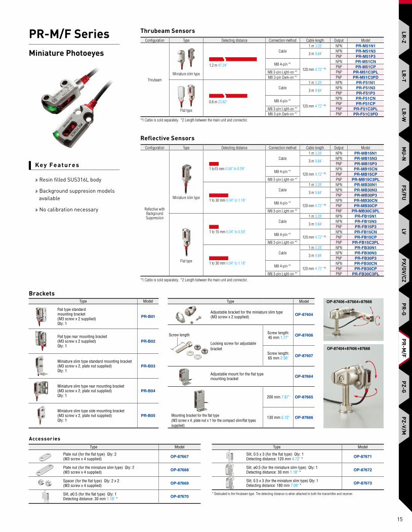
PR-M/F SeriesMiniature Photoeyes
Key Fe ature s
≥ Resin filled SUS316L body
≥ Background suppresion models available
≥ No calibration necessary
Thrubeam Sensors
Reflective Sensors
BracketsType Model
Adjustable bracket for the miniature slim type(M3 screw x 2 supplied) OP-87404
Locking screw for adjustable bracket
Screw length:45 mm 1.77" OP-87406
Screw length: 65 mm 2.56" OP-87407
Adjustable mount for the flat type mounting bracket OP-87664
Mounting bracket for the flat type(M3 screw x 4, plate nut x 1 for the compact slim/flat types supplied)
200 mm 7.87" OP-87665
130 mm 5.12" OP-87666
Screw length
OP-87404+87406+87668
OP-87406+87664+87666
AccessoriesType Model
Plate nut (for the flat type) Qty: 2(M3 screw x 4 supplied) OP-87667
Plate nut (for the miniature slim type) Qty: 2(M3 screw x 4 supplied) OP-87668
Spacer (for the flat type) Qty: 2 x 2(M3 screw x 4 supplied) OP-87669
Slit, ø0.5 (for the flat type) Qty: 1Detecting distance: 30 mm 1.18" * OP-87670
Type Model
Slit, 0.5 x 3 (for the flat type) Qty: 1Detecting distance: 120 mm 4.72" * OP-87671
Slit, ø0.5 (for the miniature slim type) Qty: 1Detecting distance: 30 mm 1.18" * OP-87672
Slit, 0.5 x 3 (for the miniature slim type) Qty: 1Detecting distance: 180 mm 7.09" * OP-87673
* Dedicated to the thrubeam type. The detecting distance is when attached to both the transmitter and receiver.
Configuration Type Detecting distance Connection method Cable length Output Model
ThrubeamMiniature slim type
1.2 m 47.24"
Cable1 m 3.28' NPN PR-M51N1
3 m 9.84'NPN PR-M51N3PNP PR-M51P3
M8 4-pin *1
120 mm 4.72" *2
NPN PR-M51CNPNP PR-M51CP
M8 3-pin Light-on *1 PNP PR-M51C3PLM8 3-pin Dark-on *1 PNP PR-M51C3PD
Flat type
0.6 m 23.62"
Cable1 m 3.28' NPN PR-F51N1
3 m 9.84'NPN PR-F51N3PNP PR-F51P3
M8 4-pin *1
120 mm 4.72" *2
NPN PR-F51CNPNP PR-F51CP
M8 3-pin Light-on *1 PNP PR-F51C3PLM8 3-pin Dark-on *1 PNP PR-F51C3PD
*1 Cable is sold separately. *2 Length between the main unit and connector.
Configuration Type Detecting distance Connection method Cable length Output Model
Reflective with Background Suppression
Miniature slim type
1 to15 mm 0.04" to 0.59"
Cable1 m 3.28' NPN PR-MB15N1
3 m 9.84'NPN PR-MB15N3PNP PR-MB15P3
M8 4-pin *1
120 mm 4.72" *2
NPN PR-MB15CNPNP PR-MB15CP
M8 3-pin Light-on *1 PNP PR-MB15C3PL
1 to 30 mm 0.04" to 1.18"
Cable1 m 3.28' NPN PR-MB30N1
3 m 9.84'NPN PR-MB30N3PNP PR-MB30P3
M8 4-pin *1
120 mm 4.72" *2
NPN PR-MB30CNPNP PR-MB30CP
M8 3-pin Light-on *1 PNP PR-MB30C3PL
Flat type
1 to 15 mm 0.04" to 0.59"
Cable1 m 3.28' NPN PR-FB15N1
3 m 9.84'NPN PR-FB15N3PNP PR-FB15P3
M8 4-pin *1
120 mm 4.72" *2
NPN PR-FB15CNPNP PR-FB15CP
M8 3-pin Light-on *1 PNP PR-FB15C3PL
1 to 30 mm 0.04" to 1.18"
Cable1 m 3.28' NPN PR-FB30N1
3 m 9.84'NPN PR-FB30N3PNP PR-FB30P3
M8 4-pin *1
120 mm 4.72" *2
NPN PR-FB30CNPNP PR-FB30CP
M8 3-pin Light-on *1 PNP PR-FB30C3PL*1 Cable is sold separately. *2 Length between the main unit and connector.
LR-Z
LR-T
FS/FUPX/GV/CZ
PR-G
PR-M
/FPZ-G
PZ-V/MLR
-WM
U-N
LV
15
PR-M
/F

PZ-G SeriesStandard Photoeyes
Key Fe ature s
≥ High power 4-element LED
≥ Extensive lineup
≥ Standard 1 inch mounting pitch
Type Design RangeModel variations Light source
(LED) Cable*1
NPN PNP Bipolar (NPN+PNP)
Standard
Rectangular
20 m 65.6'
PZ-G51N PZ-G51P —
Red
Cable (2 m 6.6')
PZ-G51CN PZ-G51CP — M8 connector
PZ-G51EN PZ-G51EP — M12 pigtail quick disconnect
Threaded— — PZ-G51B Cable (2 m 6.6')
— — PZ-G51CB M12 connector
High-power
Rectangular
40 m 131.2'
PZ-G52N PZ-G52P —
Infrared x 2
Cable (2 m 6.6')
PZ-G52CN PZ-G52CP — M8 connector
PZ-G52EN PZ-G52EP — M12 pigtail quick disconnect
Threaded— — PZ-G52B Cable (2 m 6.6')
— — PZ-G52CB M12 connector
*1 Cable sold separately for connector pigtail quick disconnect models.
Thrubeam Sensors
Type Design RangeModel variations Light source
(LED) Cable*1
NPN PNP Bipolar (NPN+PNP)
Diffuse reflectivelong-range
Rectangular
1 m 3.3'
PZ-G41N PZ-G41P —
Red
Cable (2 m 6.6')
PZ-G41CN PZ-G41CP — M8 connector
PZ-G41EN PZ-G41EP — M12 pigtail quick disconnect
Threaded— — PZ-G41B Cable (2 m 6.6')
— — PZ-G41CB M12 connector
Diffuse reflectiveshort-range
Rectangular300 mm 11.81'
PZ-G42N PZ-G42P — Cable (2 m 6.6')
PZ-G42CN PZ-G42CP — M8 connector
PZ-G42EN PZ-G42EP — M12 pigtail quick disconnect
Threaded— — PZ-G42B Cable (2 m 6.6')
— — PZ-G42CB M12 connector
Narrow-view reflective
Rectangular200 mm
7.87'
PZ-G101N PZ-G101P — Cable (2 m 6.6')
PZ-G101CN PZ-G101CP — M8 connector
PZ-G101EN PZ-G101EP — M12 pigtail quick disconnect
Threaded— — PZ-G101B Cable (2 m 6.6')
— — PZ-G101CB M12 connector
Definite reflective
Rectangular 5 to 45mm
0.20' to 1.77'
PZ-G102N PZ-G102P — Cable (2 m 6.6')
PZ-G102CN PZ-G102CP — M8 connector
PZ-G102EN PZ-G102EP — M12 pigtail quick disconnect
Threaded— — PZ-G102B Cable (2 m 6.6')
— — PZ-G102CB M12 connector
*1 Cable sold separately for connector pigtail quick disconnect models.
Reflective Sensors
Type Design RangeModel variations Light source
(LED) Cable*2
NPN PNP Bipolar (NPN+PNP)
Long-range(with P. R. O. function)
Rectangular4.2 m13.8'
PZ-G61N PZ-G61P —
Red
Cable (2 m 6.6')
PZ-G61CN PZ-G61CP — M8 connector
PZ-G61EN PZ-G61EP — M12 pigtail quick disconnect
Threaded— — PZ-G61B Cable (2 m 6.6')
— — PZ-G61CB M12 connector
Transparentobjectdetection
Rectangular1 m3.3'
PZ-G62N PZ-G62P —
Infrared
Cable (2 m 6.6')
PZ-G62CN PZ-G62CP — M8 connector
PZ-G62EN PZ-G62EP — M12 pigtail quick disconnect
Threaded— — PZ-G62B Cable (2 m 6.6')
— — PZ-G62CB M12 connector
*1 Reflector sold separately for retro-reflective models.*2 Cable sold separately for connector pigtail quick disconnect models.
Retro-Reflective Sensors
Brackets
Reflectors
Model For use with:Detecting distance (m ft)
PZ-G61Long-range
PZ-G62Transparent object detection
OP-84219
Retro-reflective models
0.1 to 4.2 0.3' to 13.8' 0.1 to 1 0.3' to 3.3'
R-3 0.1 to 2.9 0.3' to 9.5' 0.1 to 0.4 0.3' to 1.3'
R-5 0.1 to 2.5 0.3' to 8.2' 0.1 to 0.5 0.3' to 1.6'
OP-84221 0.2 to 0.7 0.7' to 2.3' —
OP-84219 (R-2L) OP-96436 (R-3)
R-5 OP-84221
PZ-B41A
PZ-B11 PZ-B31PZ-B32
PZ-B31 is shown.* PZ-B32 is symmetrical.
PZ-B23PZ-B24
* PZ-B24 is symmetrical
PZ-B23 is shown
PZ-B82 PZ-B81
PZ-B01A PZ-B61
LR-Z
LR-T
FS/F
ULV
PX/G
V/CZ
PR-G
PR-M
/FPZ
-GPZ
-V/M
LR-W
MU
-N
16
PZ-G

PZ-V/M SeriesPosition Based Photoeyes
Key Fe ature s
≥ Position based detection is less affected by color changes
≥ Internal metal threads ensure secure mounting
≥ Digital display models available
Type AdjustmentModel
Connector / Cable Detecting distanceNPN PNP
ThrubeamTrimmer
PZ-M51 PZ-M51P – / 2 m 6.6'
10 m 32.8'PZ-M52 PZ-M52P M8 connector / 0.13 m 0.43'
PZ-M53 PZ-M53P M12 connector / 0.3 m 0.98'
Thrubeam Sensors
Type AdjustmentModel
Connector / Cable Detecting distanceNPN PNP
Polarized retro-reflective (with
P.R.O. function 1.) Trimmer
PZ-M61 PZ-M61P – / 2 m 6.6'
1.5 m 4.9'PZ-M62 PZ-M62P M8 connector / 0.13 m 0.43'
PZ-M63 PZ-M63P M12 connector / 0.3 m 0.98'
PZ-M65 2. – – / 2 m 6.6'
1. The P.R.O. function allows mirror-surfaced targets to be detected stably due to the polarizing filters built into the sensor.
Retro-Reflective Sensors
Intelligent Reflective Sensors
Type AdjustmentModel
Connector / Cable Detecting distanceNPN PNP
Intelligent reflective
Trimmer
PZ-M71 PZ-M71P – / 2 m 6.6'
900 mm 35.43"PZ-M72 PZ-M72P M8 connector / 0.13 m 0.43'
PZ-M73 PZ-M73P M12 connector / 0.3 m 0.98'
PZ-M75 2. – – / 2 m 6.6'
PZ-M31 PZ-M31P – / 2 m 6.6'
300 mm 11.81"PZ-M32 PZ-M32P M8 connector / 0.13 m 0.43'
PZ-M33 PZ-M33P M12 connector / 0.3 m 0.98'
PZ-M35 2. PZ-M35P 2. – / 2 m 6.6'
PZ-M11 PZ-M11P – / 2 m 6.6'
100 mm 3.94"PZ-M12 PZ-M12P M8 connector / 0.13 m 0.43'
PZ-M13 PZ-M13P M12 connector / 0.3 m 0.98'
PZ-M15 2. – – / 2 m 6.6'
PUSH
Auto
PZ-V71 PZ-V71P – / 2 m 6.6'
900 mm 35.43"PZ-V72 PZ-V72P M8 connector / 0.13 m 0.43'
PZ-V73 PZ-V73P M12 connector / 0.3 m 0.98'
PZ-V75 2. – – / 2 m 6.6'
PZ-V31 PZ-V31P – / 2 m 6.6'
300 mm 11.81"PZ-V32 PZ-V32P M8 connector / 0.13 m 0.43'
PZ-V33 PZ-V33P M12 connector / 0.3 m 0.98'
PZ-V35 2. PZ-V35P 2. – / 2 m 6.6'
PZ-V11 PZ-V11P – / 2 m 6.6'
100 mm 3.94"PZ-V12 PZ-V12P M8 connector / 0.13 m 0.43'
PZ-V13 PZ-V13P M12 connector / 0.3 m 0.98'
PZ-V15 2. – – / 2 m 6.6'
2. Different frequency type
PZ-B41A
Brackets
PZ-B11 PZ-B31/PZ-B32
PZ-B31 is shown.* PZ-B32 is symmetrical.
PZ-B81 PZ-B01A PZ-B61 PZ-B21A/PZ-B22A
PZ-B21A is shown.* PZ-B22A is symmetrical.
Model Detecting distance
R-5 (*) 0.1 m to 1.5 m 0.3' to 4.9'
R-2 0.15 m to 2.6 m 0.53' to 8.5'
R-3 0.15 m to 1.9 m 0.53' to 6.2'
OP-96629 0.2 m to 0.9 m 0.7' to 3.0'
(*) R-5 reflector is included in PZ-M6x
Reflectors
R-2 OP-96436 (R-3) R-5 OP-96629
LR-Z
LR-T
FS/FUPX/GV/CZ
PR-G
PR-M
/FPZ-G
PZ-V/MLR
-WM
U-N
LV
17
PZ-V/M
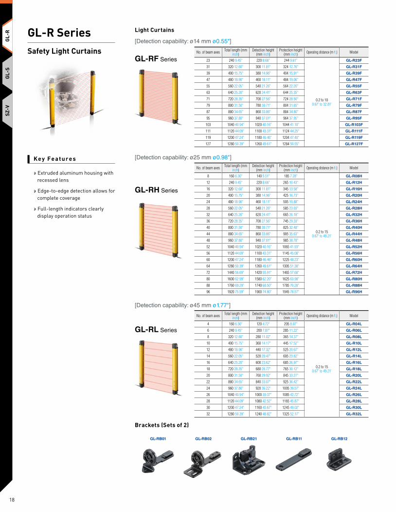
Key Fe ature s
≥ Extruded aluminum housing with recessed lens
≥ Edge-to-edge detection allows for complete coverage
≥ Full-length indicators clearly display operation status
Light Curtains
No. of beam axes Total length (mm inch)
Detection height (mm inch)
Protection height (mm inch) Operating distance (m ft.) Model
23 240 9.45" 220 8.66" 244 9.61"
0.2 to 10 0.67' to 32.81'
GL-R23F
31 320 12.60" 300 11.81" 324 12.76" GL-R31F
39 400 15.75" 380 14.96" 404 15.91" GL-R39F
47 480 18.90" 460 18.11" 484 19.06" GL-R47F
55 560 22.05" 540 21.26" 564 22.20" GL-R55F
63 640 25.20" 620 24.41" 644 25.35" GL-R63F
71 720 28.35" 700 27.56" 724 28.50" GL-R71F
79 800 31.50" 780 30.71" 804 31.65" GL-R79F
87 880 34.65" 860 33.86" 884 34.80" GL-R87F
95 960 37.80" 940 37.01" 964 37.95" GL-R95F
103 1040 40.94" 1020 40.16" 1044 41.10" GL-R103F
111 1120 44.09" 1100 43.31" 1124 44.25" GL-R111F
119 1200 47.24" 1180 46.46" 1204 47.40" GL-R119F
127 1280 50.39" 1260 49.61" 1284 50.55" GL-R127F
GL-RF Series
[Detection capability: ø14 mm ø0.55"]
No. of beam axes Total length (mm inch)
Detection height (mm inch)
Protection height (mm inch) Operating distance (m ft.) Model
8 160 6.30" 140 5.51" 185 7.28"
0.2 to 150.67' to 49.21'
GL-R08H
12 240 9.45" 220 8.66" 265 10.43" GL-R12H
16 320 12.60" 300 11.81" 345 13.58" GL-R16H
20 400 15.75" 380 14.96" 425 16.73" GL-R20H
24 480 18.90" 460 18.11" 505 19.88" GL-R24H
28 560 22.05" 540 21.26" 585 23.03" GL-R28H
32 640 25.20" 620 24.41" 665 26.18" GL-R32H
36 720 28.35" 700 27.56" 745 29.33" GL-R36H
40 800 31.50" 780 30.71" 825 32.48" GL-R40H
44 880 34.65" 860 33.86" 905 35.63" GL-R44H
48 960 37.80" 940 37.01" 985 38.78" GL-R48H
52 1040 40.94" 1020 40.16" 1065 41.93" GL-R52H
56 1120 44.09" 1100 43.31" 1145 45.08" GL-R56H
60 1200 47.24" 1180 46.46" 1225 48.23" GL-R60H
64 1280 50.39" 1260 49.61" 1305 51.38" GL-R64H
72 1440 56.69" 1420 55.91" 1465 57.68" GL-R72H
80 1600 62.99" 1580 62.20" 1625 63.98" GL-R80H
88 1760 69.29" 1740 68.50" 1785 70.28" GL-R88H
96 1920 75.59" 1900 74.80" 1945 76.57" GL-R96H
GL-RH Series
[Detection capability: ø25 mm ø0.98"]
No. of beam axes Total length (mm inch)
Detection height (mm inch)
Protection height (mm inch) Operating distance (m ft.) Model
4 160 6.30" 120 4.72" 205 8.07"
0.2 to 150.67' to 49.21'
GL-R04L
6 240 9.45" 200 7.87" 285 11.22" GL-R06L
8 320 12.60" 280 11.02" 365 14.37" GL-R08L
10 400 15.75" 360 14.17" 445 17.52" GL-R10L
12 480 18.90" 440 17.32" 525 20.67" GL-R12L
14 560 22.05" 520 20.47" 605 23.82" GL-R14L
16 640 25.20" 600 23.62" 685 26.97" GL-R16L
18 720 28.35" 680 26.77" 765 30.12" GL-R18L
20 800 31.50" 760 29.92" 845 33.27" GL-R20L
22 880 34.65" 840 33.07" 925 36.42" GL-R22L
24 960 37.80" 920 36.22" 1005 39.57" GL-R24L
26 1040 40.94" 1000 39.37" 1085 42.72" GL-R26L
28 1120 44.09" 1080 42.52" 1165 45.87" GL-R28L
30 1200 47.24" 1160 45.67" 1245 49.02" GL-R30L
32 1280 50.39" 1240 48.82" 1325 52.17" GL-R32L
GL-RL Series
[Detection capability: ø45 mm ø1.77"]
Brackets (Sets of 2)
GL-RB01 GL-RB02 GL-RB21 GL-RB11 GL-RB12
GL-R SeriesSafety Light Curtains
GL-S
SZ-V
18
GL-R
GL-R

Wiring system Optical synchronization system One-line system Wire synchronization system
Wiring diagram
Transmitter Receiver Transmitter Receiver Transmitter Receiver
ApplicableCables
Transmitter 5-core cable Series connection cable 7-core cable11-core cable
Receiver 5-core cable11-core cable
5-core cable11-core cable
7-core cable11-core cable
Shape No. of conductors PNP/NPN Connector Length (m ft.) Model
Unit connection cable
5-corePNP
— 5 16.40' GL-RP5P— 10 32.81' GL-RP10P
NPN— 5 16.40' GL-RP5N— 10 32.81' GL-RP10N
7-corePNP
— 5 16.40' GL-RP5PS— 10 32.81' GL-RP10PS
NPN— 5 16.40' GL-RP5NS— 10 32.81' GL-RP10NS
11-corePNP
— 5 16.40' GL-RP5PM— 10 32.81' GL-RP10PM
NPN— 5 16.40' GL-RP5NM— 10 32.81' GL-RP10NM
Unit connection cable (for extension use)
5-corePNP M12 (5-pin
male)
0.3 0.98'
GL-RPC03PNPN GL-RPC03N
7-corePNP M12 (8-pin
male)GL-RPC03PS
NPN GL-RPC03NS
11-corePNP M14 (12-pin
male)GL-RPC03PM
NPN GL-RPC03NM
The connector shape for both sides is the same.
Series connection cable PNP/NPN shared —
0.08 0.26' GL-RS0080.15 0.49' GL-RS015 0.5 1.64' GL-RS05
1 3.28' GL-RS13 9.84' GL-RS35 16.40' GL-RS5
10 32.81' GL-RS10
Cables (Sold Individually)
Cables (Extension)Shape No. of conductors PNP/NPN Length (m ft.) Model
Extension cable
5-coreM12 connector(5-pin female)
PNP/NPNshared
5 16.40' GL-RC510 32.81' GL-RC1020 65.62' GL-RC20
7-coreM12 connector(8-pin female)
5 16.40' GL-RC5S10 32.81' GL-RC10S20 65.62' GL-RC20S
11-coreM14 connector(12-pin female)
5 16.40' GL-RC5M10 32.81' GL-RC10M20 65.62' GL-RC20M
Relay Cables (Sold as a Pair)
Optional Relay and Power Supply
TypeSafety input
Safety output Other I/O ModelLight curtain
Safety relay1 ch (2 inputs)
(Dedicated for GL-R)1 channel
(2 outputs)
EDM input, Muting input, AUX output,
Muting lamp output, etc.GL-T11R
Type Input power supply voltage Output voltage Output capacityPower
consumptionModel
Switching type power supply
100 to 240 VAC±10% (50/60 Hz)
24 VDC ±10%Class 2
1.8 A 135 VA SL-U2
GL-T11RSL-U2
Shape Length (m ft.) Model0.3 0.98' GL-RPT03PM3 9.84' GL-RPT3PM5 16.40' GL-RPT5PM
10 32.81' GL-RPT10PM
10 32.81' GL-RCT10PM
(Common to transmitter/receiver)
M14 male connector
(Common to transmitter/receiver)
M14 male connectorM14 female connector
GL-R SeriesSafety Light Curtains
Key Fe ature s
≥ Extruded aluminum housing with recessed lens
≥ Edge-to-edge detection allows for complete coverage
≥ Full-length indicators clearly display operation status
GL-SSZ-V
19
GL-RGL-R

Cables (One-Line System)
2. Select the unit connection cable
Series connection cable
(This cable is also used for series connections.)
One-line system
dedicated cableQuantity: 1
Output type Length Model
PNP2 m 6.6' GL-SP2P1
5 m 16.4' GL-SP5P110 m 32.8' GL-SP10P1
NPN2 m 6.6' GL-SP2N1
5 m 16.4' GL-SP5N110 m 32.8' GL-SP10N1
Standard cable
Length Model0.07 m 0.2' GL-SS0070.15 m 0.5' GL-SS0150.5 m 1.6' GL-SS051 m 3.3' GL-SS12 m 6.6' GL-SS23 m 9.8' GL-SS3
5 m 16.4' GL-SS5
(Center indicatorcannot be controlled externally when using the M12 connector cable.)
Unit connection cable
Quantity: 1
Output type Length ModelPNP 0.3 m
1.0'GL-SPC03P
NPN GL-SPC03N
Extension cable
(M12 to bare leads)
Quantity: 1
Length Model2 m 6.6' OP-757215 m 16.4' OP-8727210 m 32.8' OP-85502
Extension cable
(M12 to M12)
Quantity: 1
Length Model2 m 6.6' OP-85503
5 m 16.4' OP-85504
1. Select the length of the series connection cable for use between the transmitter and receiver
M12 connector cable
Cables (Optical Synchronization)
(Center indicatorcannot be controlled externally when using the M12 connector cable.)
Unit connection cable
Quantity: 1
Output type Length ModelPNP 0.3 m
1.0'GL-SPC03P
NPN GL-SPC03N
Extension cable
(M12 to bare leads)
Quantity: 1
Length Model2 m 6.6' OP-757215 m 16.4' OP-8727210 m 32.8' OP-85502
Extension cable
(M12 to M12)
Quantity: 1
Length Model2 m 6.6' OP-85503
5 m 16.4' OP-85504
M12 connector cableStandard cables
Output type Length Model
PNP2 m 6.6' GL-SP2P
5 m 16.4' GL-SP5P10 m 32.8' GL-SP10P
NPN2 m 6.6' GL-SP2N
5 m 16.4' GL-SP5N10 m 32.8' GL-SP10N
Quantity: 1 (set includes transmitter and receiver)
Cables (Wired Synchronization)
Standard cables Output type Length Model
PNP2 m 6.6' GL-SP2P
5 m 16.4' GL-SP5P10 m 32.8' GL-SP10P
NPN2 m 6.6' GL-SP2N
5 m 16.4' GL-SP5N10 m 32.8' GL-SP10N
Quantity: 1 (set includes transmitter and receiver)
Key Fe ature s
≥ Two unique space-saving designs
≥ Large status indicators that can be externally controlled
≥ Tool free connectors and brackets for seamless integration
Slim type(Detection capability: ø25 mm ø0.98")
Flat type(Detection capability: ø25 mm ø0.98")
Light Curtains
Total length(mm inch) No. of beam axes Detection height
(mm inch)Protection height
(mm inch)Detection capability (Beam axis spacing) Operating distance Slim type Flat type
Model Model179.5 7.07" 8 140 5.51" 186 7.32"
ø25 mm ø0.98"(20 mm 0.79"
spacing)
0.1 to 2 m0.3' to 6.6'
GL-S08SH GL-S08FH259.5 10.22" 12 220 8.66" 266 10.47" GL-S12SH GL-S12FH339.5 13.37" 16 300 11.81" 346 13.62" GL-S16SH GL-S16FH419.5 16.52" 20 380 14.96" 426 16.77" GL-S20SH GL-S20FH499.5 19.67" 24 460 18.11" 506 19.92" GL-S24SH GL-S24FH579.5 22.81" 28 540 21.26" 586 23.07" GL-S28SH GL-S28FH659.5 25.96" 32 620 24.41" 666 26.22" GL-S32SH GL-S32FH739.5 29.11" 36 700 27.56" 746 29.37" GL-S36SH GL-S36FH819.5 32.26" 40 780 30.71" 826 32.52" GL-S40SH GL-S40FH
GL-S SeriesSafety Light Curtains
GL-S
SZ-V
20
GL-R
GL-S
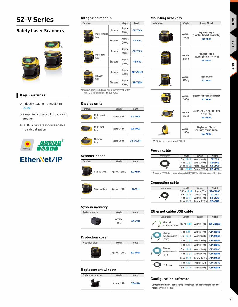
Connection cableAppearance Length Weight Model
0.05 m 0.16' Approx. 80 g SZ-VS0055 m 16.40' Approx. 350 g SZ-VS510 m 32.81' Approx. 700 g SZ-VS1020 m 65.62' Approx. 1300 g SZ-VS20
Function Weight Model
Multi-function type
Approx. 420 g SZ-VU04
Multi-bank type
Approx. 420 g SZ-VU32
Network type
Approx. 600 g SZ-VU32N
Display units
Function Weight Model
Camera type Approx. 1600 g SZ-VH1X
Standard type Approx. 1600 g SZ-VH1
Scanner heads
System memory Weight Model
Approx.
60 gSZ-VSM
System memory
Appearance Length Weight Model
Main unit connection cable
0.3 m 0.98' Approx. 110 g SZ-VNC03
Ethernet extension cable (RJ45)
2 m 6.56' Approx. 160 g OP-88086
5 m 16.40' Approx. 340 g OP-88087
10 m 32.81' Approx. 660 g OP-88088
Ethernet extension cable (M12)
2 m 6.56' Approx. 160 g OP-88089
5 m 16.40' Approx. 340 g OP-88090
10 m 32.81' Approx. 660 g OP-88091
20 m 65.62' Approx. 1280 g OP-88092
USB cable2 m 6.56' Approx. 70 g OP-51580
5 m 16.40' Approx. 200 g OP-86941
Ethernet cable/USB cable
Replacement window Weight Model
Approx. 130 g SZ-VHW
Replacement window
Protection cover Weight Model
Approx. 1000 g SZ-VB21
Protection cover
Configuration software <Safety Device Configurator> can be downloaded from the KEYENCE website for free.
Configuration software
* Integrated models include display unit, scanner head, system memory and a connection cable (SZ-VS005).
Function Weight Model
Multi-function type
CameraApprox.
2100 gSZ-V04X
StandardApprox.
2100 gSZ-V04
Multi-bank type
CameraApprox.
2100 gSZ-V32X
StandardApprox.
2100 gSZ-V32
Network type
CameraApprox.
2300 gSZ-V32NX
StandardApprox.
2300 gSZ-V32N
Integrated models
* SZ-VB13 cannot be used with SZ-VU32N.
Installation Weight Name · Model
Approx. 900 g
Adjustable angle mounting bracket (horizontal)
SZ-VB01
Approx. 1800 g
Adjustable angle mounting bracket (vertical)
SZ-VB02
Approx. 1350 g
Floor bracket
SZ-VB03
Approx. 700 g
Display unit standard bracket
SZ-VB11
Approx. 350 g
Display unit DIN rail mounting bracket (flat)
SZ-VB12
Approx. 350 g
Display unit DIN rail mounting bracket (slim)
SZ-VB13
Mounting brackets
Key Fe ature s
≥ Industry leading range 8.4 m (27.56')
≥ Simplified software for easy zone creation
≥ Built-in camera models enable true visualization
SZ-V SeriesSafety Laser Scanners
Appearance Length Weight Model5 m 16.40' Approx. 400 g SZ-VP510 m 32.81' Approx. 800 g SZ-VP1020 m 65.62' Approx. 1500 g SZ-VP2030 m 98.43' Approx. 2200 g SZ-VP30
Power cable
* When using PROFIsafe communication, contact KEYENCE for additional power cable options.
GL-SSZ-V
21
GL-RSZ-V

Flow Meters
Accessories
Cabling
Key Fe ature s
≥ No pipe modifications necessary
≥ Compatible with countless liquids and pipe materials
≥ Integrated temperature monitoring
FD-R SeriesClamp-On Flow Meters
Supported pipe size (Outer diameter) Appearance Rated flow
velocity range Flow rate range (Typical) Weight Model
1 1/2" (40A)(ø44 to ø55)
0.3 m/s to
5 m/s
36 to 400 L/min 9 to 100 gal/min 2.4 to 24 m3/h
Approx. 2.5 kg
FD-R50
2" (50A)(ø55 to ø64)
36 to 600 L/min 9 to 150 gal/min 2.4 to 36 m3/h
2 1/2" (65A)(ø64 to ø83)
90 to 1000 L/min 24 to 260 gal/min 5.4 to 60 m3/h
Approx. 3.0 kg
FD-R80
3" (80A)(ø83 to ø100)
90 to 1500 L/min 24 to 390 gal/min 5.4 to 90 m3/h
4" (100A)(ø100 to ø127)
220 to 2500 L/min 60 to 660 gal/min 12 to 150 m3/h
Approx. 3.3 kg
FD-R125
5" (125A)(ø127 to ø152)
220 to 3700 L/min 60 to 990 gal/min 12 to 220 m3/h
6" (150A)(ø152 to ø191)
570 to 5500 L/min 150 to 1400 gal/min 36 to 330 m3/h
Approx. 3.5 kg
FD-R200
8" (200A)(ø191 to ø220)
570 to 9500 L/min 150 to 2500 gal/min 36 to 570 m3/h
*The minimum flow rates (zero cut flow rates) can be changed in the settings.
Description Appearance Usage Weight Model
Protection coverPrevent damage to the main unit or
unintended settings changes Material : SUS304, Polycarbonate
Approx. 285 g
FD-RP1
Modular cable
Send recorded data stored in FD-R to a computer
Approx. 72 g
OP-26487
RS-232C conversion adapter [9-pin]
Approx. 25 g
OP-26401
DC Power Options: M12 4‐Pin Cable, please see page 31.AC Power Options: Please contact KEYENCE representative for more information.
FD-Q
GP-M
APFL
FD-R
22
FD-R

GP-M Series
Key Fe ature s
≥ Multiple adapter options ensure fit
≥ Clog resistent step flush diaphram
≥ Rotatable display requiring no union joint
Sensors
Accessories
Appearance Rated pressure range Fluid type Thread diameter Model
-14.50 to +14.50 PSI (-100 to +100 kPa)
GasLiquid
G3/4
GP-M001
-14.5 to +145.0 PSI (-0.1 to +1 MPa) GP-M010
-14.5 to +362.6 PSI (-0.1 to +2.5 MPa) GP-M025
0 to +1450 PSI (0 to +10 MPa)
Liquid
GP-M100
0 to +3626 PSI (0 to +25 MPa) GP-M250
0 to+5802 PSI (0 to +40 MPa) GP-M400
0
Adapters
Appearance Type Model
R male 1/8 OP-87281
R male 1/4 OP-87282
R male 3/8 OP-87280
G female 1/4 OP-87283
NPT male 1/8 OP-87284
NPT male 1/4 OP-87285
Rc female 1/2 OP-87286
Do not use unauthorized adapters.
Display protection cover
Appearance Material Model
Polysulfone OP-87289
Throttles (Attach to the adapter before use.)
Appearance Material Applicable adapter Model
SUS303OP-87280/OP-87281OP-87282/OP-87284
OP-87285OP-87311
SUS303 OP-87283 OP-87312
It is recommended to attach a throttle to the GP-M100/M250/M400. For the other models, use it when excessive pulses or surge pressure is expected.
Appearance Name Material Model
Display Protection Cover Polysulfone FD-QP1
Key Fe ature s
≥ No pipe modifications necessary
≥ Detects a large variety of liquid types
≥ Adapts to all sorts of pipe materials
Sensors
Accessory
Appearance Rated flow range Supported pipe size Model
20 L/min5.2 G/min
1/4"(8 A)
FD-Q10C
30 L/min7.9 G/min
3/8"(10 A)
60 L/min15.9 G/min
1/2"(15 A)
FD-Q20C
100 L/min26.4 G/min
3/4"(20 A)
200 L/min52.8 G/min
1"(25 A)
FD-Q32C
300 L/min79.3 G/min
1 1/4"(32 A)
400 L/min105.7 G/min
1 1/2"(40 A)
FD-Q50C
500 L/min132.1 G/min
2"(50 A)
FD-Q SeriesClamp-On Flow Sensors
GP-MAP
FD-R
FD-Q
FL
23
GP-MFD
-Q

AccessoriesAP-B01 AP-B02 AP-B03 AP-B04 AP-A01
Mounting example
Amplifiers
Type AppearanceModel
NPN PNP
DINMain Unit AP-V41AW AP-V41AWP
Expansion unit AP-V42AW AP-V42AWP
Cube AP-C40W AP-C40WP
* For DIN rail mounting type units, up to 8 expansion units can be used with 1 main unit. Main units include mounting brackets and expansion units include end units.
Sensor Heads
ConfigurationRated
pressure range*Type -29.9 inchHg 29.9 inchHg0 145 PSI Model
0 to -29.9 inchHg Negative pressure AP-41M
0 to -29.9 inchHg Negative pressure AP-41
0 to 145.0 PSI Positive pressure AP-43
29.9 to -29.9 inchHg Compound pressure AP-44
*The set pressure range is between -15% and +110% of the rated pressure range.
AP-B01 AP-B02 AP-B03 AP-B04 AP-A01
Horizontalmounting bracket
Wall mountingbracket
Nameplateceiling mountingbracket
Aslant mountingbracket
Panel mountingbracket
Mountingexample
AP-C30 Series
AP-C40/V40 Series
AP-V80 Series
Key Fe ature s
≥ Compact size
≥ Large display
≥ Various mounting options
Key Fe ature s
≥ Small heads
≥ Fast response time
≥ Pre-programmed modes for various applications
Key Fe ature s
≥ IP67 full stainless steel structure
≥ Up to 7,250 PSI range
≥ Up to 100°C (212°F) heat resistance
Sensors
Accessories
Type Multi range Negative pressure Positive pressure
ModelNPN AP-C30K AP-C31K AP-C33KPNP AP-C30KP AP-C31KP AP-C33KP
Appearance
145 PSI
29.9 inchHg
0
-29.9 inchHg
Rated pressure rangeNegative pressure mode Positive pressure mode Compound pressure
mode0 to -29.9 inchHg 0 to 145 PSI
0 to -29.9 inchHg 0 to 29.5 inchHg
+29.9 to -29.9 inchHg
ResolutionNegative pressure Positive pressure Compound pressure 0.1 inchHg (Normal mode) 0.2 PSI (Normal mode)
0.1 inchHg 0.1 inchHg 0.1 inchHg 0.01 inchHg (Focus mode) 0.02 PSI (Focus mode)
AccessoriesAmplifiers
Type AppearanceModel
NPN PNP
DIN
Standard AP-V80W AP-V80WP
Differential pressure AP-V82W AP-V82WP
CubeStandard AP-V85W AP-V85WPDifferential pressure AP-V87W AP-V87WP
Appearance Designation Model
Panel mounting bracket kit for AP-V85W(P) OP-51476
Panel spacer kit forAP-V85W(P) OP-51605
Head connectors (x2) OP-42367
Sensor Heads
Appearance Pressure port Pressure type Model
Sensor head
Pressure port
NPT1/8
Compound -29.9 to +29.9 inchHg AP-10SK
Negative -29.9 to 0 inchHg AP-11SK
Positive (Low) 0 to 14.5 PSI AP-12SK
Pos i t i ve 0 to 145 PSI AP-13SK
NPT1/4
(with a throttle)Pos i t i ve (H igh)
0 to 1,450 PSI AP-14SK
0 to 2,900 PSI AP-15SK
0 to 7,250 PSI AP-16SK
-29.9 0 29.9 145.0 1,450 2,900 7,250
Includes brackets for installation without DIN rail.
OP-51605
AP-V85W
FD-Q
GP-M
APFL
FD-R
24
AP

3 Different Models Designed for Varying Applications
Standard typeFL‐001
Sanitary typeFL‐S001
Plastic/Chemical typeFL‐C001
• Water/oil model• Applicable for liquids containing
solid particulates• Applicable for viscous liquids
• Food/chemical industry model• Ready for CIP/SIP cleaning• Applicable for viscous liquids
• Chemical tank model• Applicable for corrosive liquids• Applicable for viscous liquids
Key Fe ature s
≥ Completely trouble-free operation
≥ Sensing Guide-Pulse Technology
≥ Multiple output options
FL SeriesLiquid Level Sensors
AccessoriesAppearance Type Description Model
Gasket for FL-001(Inorganic fiber + Oil-
resistant rubber)Seal material for improved mounting sealability. OP-87548
Condensation preventionattachment for FL-001
(SUS303)
Installing this attachment between the device and the tank prevents condensation when the medium is at a lower temperature than the ambient temperature and condensation forms on the bottom of the device.Includes two gaskets (OP-87548).
OP-87551
Flange plate for FL-001 (SUS303)
Corresponding to G3/4 JIS5K50A
- OP-87573
Corresponding to G3/4 JIS5K65A
Use for mounting via a flange plate.Includes one gasket (OP-87548). OP-87574
Nut for FL-001 G3/4 (SUS303)
Use for mounting to the toppanel with a nut. OP-87642
Standard ModelCONTROLLER (Required) PROBE (Required)
Standard typeFL-001
FL-P20 (200 mm 0.66')FL-P40 (400 mm 1.31')FL-P60 (600 mm 1.97')FL-P80 (800 mm 2.62')FL-P100 (1000 mm 3.28')FL-P120 (1200 mm 3.94')FL-P140 (1400 mm 4.59')FL-P160 (1600 mm 5.25')FL-P180 (1800 mm 5.91')FL-P200 (2000 mm 6.56')
CablesAppearance Standard power supply cable Model
Straight cableOP-87564 (2 m 6.6')OP-87565 (5 m 16.4')OP-87566 (10 m 32.8')
The following are standard PVC cables.
OP-87564OP-87565OP-87566
L-shaped cableOP-87568 (2 m 6.6')OP-87569 (5 m 16.4')OP-87570 (10 m 32.8')
OP-87568OP-87569OP-87570
Zinc die-casting (Nickel plated)
PVC
Zinc die-casting (Nickel plated)
PVC
GP-MAP
FD-R
FD-Q
FL
25
FL

Appearance Oil-resistant power supply cable Model
Straight cablesOP-87582 (2 m 6.6')OP-87583 (5 m 16.4')OP-87584 (10 m 32.8')
The following are PUR cables with high resistance to oil environments.
OP-87582OP-87583OP-87584
L-shaped cablesOP-87586 (2 m 6.6')OP-87587 (5 m 16.4')OP-87588 (10 m 32.8')
OP-87586OP-87587OP-87588
Cables
SUS316L
PVC
SUS316L
PVC
Key Fe ature s
≥ Completely trouble-free operation
≥ Sensing Guide-Pulse Technology
≥ Multiple output options
FL SeriesLiquid Level Sensors
AccessoriesAppearance Type Description Model
Cap for FL-S001 (included with FL-S001)
This cap offers improved waterproof performance beyond the IP67 rating of the device with no cap. The cap includes a transparent plastic window on the top for checking the display.Material: SUS304, PPSU, EPDM
OP-87558
Sanitary ModelCONTROLLER (Required) PROBE (Required)
Sanitary typeFL-S001
FL-SP20 (200 mm 0.66')FL-SP40 (400 mm 1.31')FL-SP60 (600 mm 1.97')FL-SP80 (800 mm 2.62')FL-SP100 (1000 mm 3.28')FL-SP120 (1200 mm 3.94')FL-SP140 (1400 mm 4.59')FL-SP160 (1600 mm 5.25')FL-SP180 (1800 mm 5.91')FL-SP200 (2000 mm 6.56')
Appearance Stainless steel power supply cable Model
Straight cablesOP-87647 (2 m 6.6')OP-87648 (5 m 16.4')OP-87649 (10 m 32.8')
The following are PVC cables with stainless steel (SUS316L) connectors. Use in situations where rust is a concern for the connectors.
OP-87647OP-87648OP-87649
L-shaped cablesOP-87650 (2 m 6.6')OP-87651 (5 m 16.4')OP-87652 (10 m 32.8')
OP-87650OP-87651OP-87652
Cables
SUS316L
PVC
SUS316L
PVC
Plastic/Chemical ModelCONTROLLER (Required) PROBE (Required)
Plastic/Chemical typeFL-C001
FL-CP20 (200 mm 0.66')FL-CP40 (400 mm 1.31')FL-CP60 (600 mm 1.97')FL-CP80 (800 mm 2.62')FL-CP100 (1000 mm 3.28')FL-CP120 (1200 mm 3.94')FL-CP140 (1400 mm 4.59')FL-CP160 (1600 mm 5.25')FL-CP180 (1800 mm 5.91')FL-CP200 (2000 mm 6.56')
AccessoriesAppearance Type Description Model
Tube for FL-C001This tube offers protection for the power supply cable in corrosive environments.Material: FKM, PPS
OP-87560
Gasket for FL-C001 Seal material for improved mounting sealability.
OP-87561 (FFKM)
OP-87562 (FKM)
Cap for FL-C001This cap offers protection for the operating surface of the device in corrosive environments. The cap prevents the display from being visible. An O ring (FKM) is included for the cap.
OP-87563
Flange plate for FL-C001 (PVC)Corresponding to G3/4
JIS5K50AUse for mounting via a flange plate.
OP-87577
Corresponding to G3/4 JIS5K65A OP-87578
Nut for FL-C001 G3/4 (PPS) Use for mounting to the top panel with a nut. OP-87645
FD-Q
GP-M
APFL
FD-R
26
FL

EZ Series: 3 Wire Ferrous Metal Type
Type Detecting distance Output type Enclosure rating Model
DC 3
-wire
Shielded
M8 1.5 mm 0.06"
N.O./N.C. IP67
EZ-8M
M12 2.5 mm 0.10" EZ-12M
M18 5 mm 0.20" EZ-18M
M30 10 mm 0.39" EZ-30M
Flat 5 mm 0.20" EZ-18T
EV-F Series: 2 Wire Ferrous Metal Type with Fluorocarbon Coating
Type Detecting distance Output type Enclosure rating Model
DC 2
-wire
Spatter-resistant
M12 2.5 mm 0.10"
N.O. IP67
EV-112F
M18 5 mm 0.20" EV-118F
M30 10 mm 0.39" EV-130F
DC 2
-wire
(Con
necto
r typ
e)
M12 2.5 mm 0.10" EV-112F SO(2073)
M18 5 mm 0.20" EV-118F SO(2074)
* Not chemical-resistant. If you require a chemical-resistant model, use EH-910 in a fluoropolymer-coated case.
ED Series: 3 Wire All Metal Type
Type Detecting distance Output type Enclosure rating Model
DC3-
wire
ShieldedM18 5 mm 0.20"
N.O. IP67
ED-118M
M30 11 mm 0.43" ED-130M
Non-shielded
M18 11 mm 0.43" ED-118U
M30 20 mm 0.79" ED-130U
Proximity Sensors
Key Fe ature s
≥ Various head size options available
≥ Detects both ferrous and non-ferrous metals (ED series)
≥ Fluorocarbon-coated type for harsh environments (EV-F series)
EV Series: 2 Wire Ferrous Metal TypeSelf-Contained Type
Type Detecting distance Output type Enclosure rating Model
DC 2
-wire
Shielded
M8 1.5 mm 0.06"
N.O. IP67
EV-108M
M12 2.5 mm 0.10" EV-112M
M18 5 mm 0.20" EV-118M
M30 10 mm 0.39" EV-130M
Non-shielded
M8 4 mm 0.16" EV-108U
M12 8 mm 0.31" EV-112U
M18 15 mm 0.59" EV-118U
M30 27 mm 1.06" EV-130U
AC 2
-wire
Shielded
M12 2.5 mm 0.10" EV-12M
M18 5 mm 0.20" EV-18M
M30 10 mm 0.39" EV-30MDC
2-w
ire (C
onne
ctor t
ype)
Shielded
M8 1.5 mm 0.06" EV-108M SO(2091)
M12 2.5 mm 0.10" EV-112M SO(2062)
M18 5 mm 0.20" EV-118M SO(2063)
M30 10 mm 0.39" EV-130M SO(2064)
Non-shielded
M12 8 mm 0.31" EV-112U SO(2065)
M18 15 mm 0.59" EV-118U SO(2066)
* Can be connected to both NPN or PNP inputs.
MS
CUProxim
ity
27
Proximity

Separate Amplifier TypeES Series: Ferrous Metal Type
Appearance Size Type Detecting distance Model
Non-shielded
ø2.8 mm ø0.11" Cylindrical 7 mm 0.28" (3 mm 0.12") EH-402
ø14.5 mm ø0.57"
Cylindrical, Threaded
13 mm 0.51" (6 mm 0.24") EH-416
ø22 mm ø0.87" 18 mm 0.71" (9 mm 0.35") EH-422
ø30 mm ø1.18" 25 mm 0.98" (12 mm 0.47") EH-430
ø40 mm ø1.57" 36 mm 1.42" (18 mm 0.71") EH-440
ø90 mm ø3.45" Cylindrical 70 mm 2.76" (35 mm 1.38") EH-290
Figures in parentheses under detecting distance indicate stable detecting distance.
ES-M Series cannot be connected to EH-422/430/440/290.
Amp-In-Cable TypeEM Series: 3 Wire Ferrous Metal Type
Type Appearance Detecting distance Enclosure rating
Model
NPN PNP
DC3-
wire
Shielded
Cylindrical
ø3 mm ø0.12" 0.6 mm 0.02"
IP67
EM-030 EM-030P
ø3.8 mm ø0.15" 0.8 mm 0.03" EM-038 EM-038P
ø5.4 mm ø0.21" 1.2 mm 0.05" EM-054 EM-054P
ø8 mm ø0.31" 2 mm 0.08" EM-080 EM-080P
Threaded
M5 1 mm 0.04" EM-005 EM-005P
M10 2 mm 0.08" EM-010 EM-010P
M14 4 mm 0.16" EM-014 EM-014P
Appearance TypeModel
NPN PNP
Main unit ES-M1 ES-M1P
Expansion unit ES-M2 ES-M2P
Amplifier
Appearance Size TypeDetecting distance
( Stable detecting distance/ Maximum detecting distance )
Model
Shielded
Cylindrical
ø2.8 mm ø0.11"
Cylindrical
1.2 mm 0.05" (0.6 mm 0.02") EH-302
ø3.8 mm ø0.15" 2 mm 0.08" (0.8 mm 0.03") EH-303A
ø5.4 mm ø0.21"3 mm 0.12" (1 mm 0.04") EH-305
Cylindrical, with spiral tube 3 mm 0.12" (1 mm 0.04") EH-305S
ø8 mm ø0.31"Cylindrical 5 mm 0.20" (2 mm 0.08") EH-308
Cylindrical, with spiral tube 5 mm 0.20" (2 mm 0.08") EH-308S
ø10 mm ø0.39" Solvent resistant 4.5 mm 0.18" (2 mm 0.08") EH-910
Threaded
M8 Threaded, oil-resistant 2.5 mm 0.10" (1.5 mm 0.06") EH-108
M10Threaded 5 mm 0.20" (2 mm 0.08") EH-110
Threaded, with spiral tube 5 mm 0.20" (2 mm 0.08") EH-110S
M14 Threaded 8 mm 0.31" (5 mm 0.20") EH-114
Flatt = 4.8 mm 0.19" Thin 8 mm 0.31" (5 mm 0.20") EH-614A
t = 3.5 mm 0.16" ULTRA Thin/Space saving 3 mm 0.12" (1 mm 0.04") EH-605
Sensor Heads
Proximity Sensors
Key Fe ature s
≥ Various head size options available
≥ Detects both ferrous and non-ferrous metals (ED series)
≥ Fluorocarbon-coated type for harsh environments (EV-F series)
MS
CUPr
oxim
ity
28
Prox
imity

Amplifier
Appearance Sensitivity adjustmentControl output (One shot)1. Output response time
Power supply ModelSolid-state RelaySolid-state2.
(NPN) Relay contact
Sensitivity selector switch
and fine-adjustment trimmer
100 mA (40 V max.)
SPDT 250 VAC 2 A 1 ms 10 ms 110/120/220/240 VAC
±10%, 50/60 Hz TA-340
1. Both the solid-state and contact outputs of the amplifier are one-shot signals; the signals turn on as the object enters the sensor head.
2. NPN output can easily be converted to PNP output by connecting the optional OP-5148 PNP Output Converter.
AmplifierAppearance Output Model
NPN ET-90
Appearance Type Smallest detectable object1. Detecting area Enclosure rating Model
Detecting minutemetallic objects
0.3 mm dia. x 0.5 mm 0.01" dia. x 0.02"
steel wire
5 mm 0.20" dia.
IP67
TH-305
10 mm0.39" dia. TH-310
0.3 mm dia. x 0.75 mm0.01" dia. x 0.03"
steel wire
15 mm0.59" dia. TH-315
0.3 mm dia. x 1.0 mm0.01" dia. x 0.04"
steel wire
20 mm0.79" dia. TH-320
Detecting smallmetallic objects
2.0 mm 0.08" dia.steel ball
50 mm1.97" dia. TH-105
2.5 mm 0.1" dia.steel ball
70 mm2.76" dia. TH-107
3.0 mm0.12" dia.steel ball
100 mm3.94" dia. TH-110
Detecting large metallic objects
5.0 mm0.20" dia.steel ball
100 x 150 mm3.94" x 5.91" TH-515
7.0 mm0.28" dia.steel ball
150 x 200 mm5.91" x 7.87" TH-520
1. Data obtained with the amplifier set at maximum sensitivity when target was travelling at 500 mm 19.69".
Proximity Sensors
Key Fe ature s
≥ Various head options available
≥ Aluminum detection possible (ET Series)
≥ Wire and passage detection models available (TA series)
Separate Amplifier TypeET Series: Aluminum Type
TA Series: Metal Passage Confirmation Type
Sensor Heads
Appearance Size Detecting distance Model
Shielded
Cylindricalø5.4 mm ø0.21" 1 mm 0.04" ET-305
ø8 mm ø0.31" 2 mm 0.08" ET-308
Threaded M10 2 mm 0.08" ET-110
Sensor Heads
MS
CUProxim
ity
29
Proximity
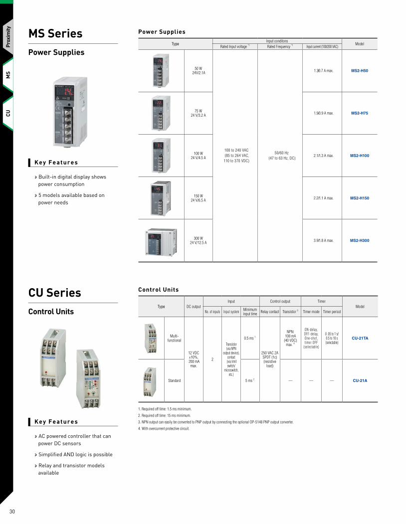
Key Fe ature s
≥ Built-in digital display shows power consumption
≥ 5 models available based on power needs
Key Fe ature s
≥ AC powered controller that can power DC sensors
≥ Simplified AND logic is possible
≥ Relay and transistor models available
TypeInput conditons
ModelRated Input voltage *1 Rated Frequency *1 Input current (100/200 VAC)
50 W 24V/2.1A
100 to 240 VAC (85 to 264 VAC, 110 to 370 VDC)
50/60 Hz (47 to 63 Hz, DC)
1.3/0.7 A max. MS2-H50
75 W24 V/3.2 A 1.9/0.9 A max. MS2-H75
100 W24 V/4.5 A 2.1/1.3 A max. MS2-H100
150 W24 V/6.5 A 2.2/1.1 A max. MS2-H150
300 W24 V/12.5 A 3.9/1.8 A max. MS2-H300
MS SeriesPower Supplies
CU SeriesControl Units
Power Supplies
Type DC outputInput Control output Timer
ModelNo. of inputs Input system Minimum
input time Relay contact Transistor 3. Timer mode Timer period
Multi-functional
12 VDC ±10%,
200 mA max.
2
Transistor (via NPN
output device), contact
(via limit switch/
microswitch, etc.)
0.5 ms 1.
250 VAC 2A SPDT (1c) (resistive
load)
NPN: 100 mA
(40 VDC) max. 4.
ON-delay, OFF-delay, One-shot, t imer OFF
(selectable)
0 .05 to 1 s/0.5 to 10 s (selectable)
CU-21TA
Standard 5 ms 2. — — — CU-21A
Control Units
1. Required off time: 1.5 ms minimum.
2. Required off time: 15 ms minimum.
3. NPN output can easily be converted to PNP output by connecting the optional OP-5148 PNP output converter.
4. With overcurrent protective circuit.
MS
CUPr
oxim
ity
30
MS
CU
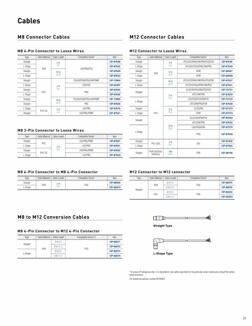
Cables
M8 Connector Cables M12 Connector Cables
M8 to M12 Conversion Cables
Type Cable Material Cable Length Compatible Series* Item
Straight
PUR
2 m6.6'
LRZ/PRG/PZG
OP-87628
L-Shape OP-87632
Straight 10 m32.8'
OP-87629
L-Shape OP-87633
Straight
PVC
2 m6.6'
FS/LRZ/PSN/PZG/LVN/PRMF OP-73864
L-Shape LRZ/PZG OP-85497
StraightPRG
OP-87625
L-Shape OP-87630
Straight 10 m32.8'
FS/LRZ/PSN/PZG/LVN/PRMF OP-73865
Straight PRG OP-87626
L-ShapePVC-SS 2 m
6.6'LRZ/PRG OP-87619
Straight LRZ/PRG/PRMF OP-87621
Type Cable Material Cable Length Compatible Series* Item
Straight
PUR
2 m 6.6'
LRT/LRZ/GPM/LRW/PRG/PZG/FDR OP-87636
L-Shape LRT/LRZ/FDQ/GPM/LRW/PRG OP-87640
Straight 5 m16.4'
GPM OP-88067
L shape GPM OP-88068
Straight 10 m32.8'
LRT/LRZ/GPM/LRW/PRG/PZG/FDR OP-87637
L-Shape LRT/LRZ/FDQ/GPM/LRW/PRG OP-87641
Straight
PVC
2 m6.6'
GLS/LRZ/PX/GPM/PZG/FDR OP-75721
LRT/LRW/PRG OP-87634
L-ShapeLRZ/FDQ/PX/GPM/PZG OP-75722
LRT/LRW/PRG/FDR OP-87638
Straight 5 m16.4'
GLS/GPM OP-87272
L-Shape GPM OP-87273
Straight
10 m32.8'
GLS/LRZ/GPM/PZG OP-85502
LRT/LRW/PRG OP-87635
L-Shape
LRZ/FDQ/GPM OP-87274
PRG OP-87639
StraightPVC-SUS 2 m
6.6' LRZOP-87402
L-Shape OP-87403
Straight PUR-SUS316L (Outdoor)
10m 32.8' FDR OP-88196
Type Cable Material Cable Length Compatible Series (*) Item
Straight
PUR
2 m 6.6'
PZG
OP-88071
5 m 16.4' OP-88072
L-Shape2 m 6.6' OP-88073
5 m 16.4' OP-88074
Type Cable Material Cable Length Compatible Series* Item
StraightPVC
2 m6.6'
LRZ/PRG/PRMF OP-87627
L-Shape LRZ/PRG OP-87631
StraightPVC-SS
LRZ/PRG/PRMF OP-87622
L-Shape LRZ/PRG OP-87620
Type Cable Material Cable Length Compatible Series* Item
StraightPUR 2 m
6.6' PZGOP-88069
L-Shape OP-88070
M8 4-Pin Connector to Loose Wires M12 Connector to Loose Wires
M8 4-Pin Connector to M12 4-Pin Connector
M8 3-Pin Connector to Loose Wires
Type Cable Material Cable Length Compatible Series* Item
Straight
PUR2 m 6.6'
PZGOP-88075
5 m 16.4' OP-88076
PVC2 m 6.6'
PZGOP-85503
5 m 16.4' OP-85504
M12 Connector to M12 connectorM8 4-Pin Connector to M8 4-Pin Connector
*To ensure IP ratings are met, it is important to use cables specified for the particular sensor series and consult the sensor series brochure.
For additional options, contact KEYENCE.
Straight Type
L-Shape Type
31

KA11-1017
KEYENCE CORPORATION OF AMERICA500 Park Boulevard, Suite 200, Itasca, IL 60143, U.S.A. PHONE: +1-201-930-0100 FAX: +1-855-539-0123
KEYENCE CANADA INC.E-mail: [email protected]
www.keyence.com SAFETY INFORMATIONPlease read the instruction manual carefully in order to safely operate any KEYENCE product.1 - 8 8 8 - 5 3 9 - 3 6 2 3
1-888-KEYENCECALL TOLL FREE
T O C O N TA C T Y O U R L O C A L O F F I C E
The information in this publication is based on KEYENCE’s internal research/evaluation at the time of release and is subject to change without notice. Company and product names mentioned in this catalog are either trademarks or registered trademarks of their respective companies. The specifications are expressed in metric units. The English units have been converted from the original metric units.
KEYENCE MEXICO S.A. DE C.V.E-mail: [email protected]
CONTACT YOUR NEAREST OFFICE FOR RELEASE STATUS
Copyright © 2018 KEYENCE CORPORATION. All rights reserved. TSSSensorlineup2-KA-C-US 1098-3 611G93
INTELLIGENT SENSING
1D/2D CODE READERSSR-2000 Series
STATIC ELIMINATORSSJ Series
CONTACT SENSORSGT2 Series
VISION SENSORSIV Series
HIGH PRECISION MEASUREMENT
LASER MEASUREMENTLK Series
LASER PROFILERLJ-V Series
2D MICROMETERTM Series
1D MICROMETERLS Series
RESEARCH AND QUALITY
HANDHELD PROBE COORDINATE MEASUREMENT MACHINEXM Series
IMAGE DIMENSION MEASUREMENT SYSTEMSIM Series
DIGITAL MICROSCOPEVHX Series
WIDE AREA 3D MEASUREMENT SYSTEMVR Series
MACHINE VISION MARKING TECHNOLOGY
VISION SYSTEMSXG & CV-X Series
MULTI-SPECTRUM LIGHTING LASER MARKINGMD & ML Series
INKJET PRINTINGMK-U Series


