Datasheet Next Generation of Self-Contained DC-Operated Sensors • Complete family of sensors, all housed in the popular 18 mm threaded metal barrel • Economical photoelectric sensors for cost sensitive and high volume installations • Powerful and bright visible red emitter beam for easy alignment and set-up • Highly visible output and dual-function power and stability indicators • Advanced ASIC technology is resistant to optical and electrical noise source • Wide operating temperature range: −40 °C to +70 °C (−40 °F to +158 °F) • Robust 250° adjustment potentiometer on select models WARNING: Not To Be Used for Personnel Protection Never use this device as a sensing device for personnel protection. Doing so could lead to serious injury or death. This device does not include the self-checking redundant circuitry necessary to allow its use in personnel safety applications. A sensor failure or malfunction can cause either an energized or de-energized sensor output condition. Models Emitter/Receiver Models 1 Model Number Range Output M18-3NAEL-2M Emitter 25 m (82 ft) None M18-3NAEJ-2M 25 m (82 ft) with beam inhibit M18-3NAES-2M 25 m (82 ft) with adjustment M18-3VNRL-2M Receiver 25 m (82 ft) Complementary NPN M18-3VPRL-2M Complementary PNP M18-3VNRS-2M 25 m (82 ft) with adjustment Complementary NPN M18-3VPRS-2M Complementary PNP Polarized Retroreflective Models 1 Model Number Range Output M18-3VNLP-2M 6 m (19.7 ft) with BRT-84 reflector Complementary NPN M18-3VPLP-2M Complementary PNP M18-3VNLPC-2M 6 m (19.7 ft) with BRT-84 reflector, with adjustment Complementary NPN M18-3VPLPC-2M Complementary PNP Retroreflective Models 1 Model Number Range Output M18-3VNLV-2M 7.5 m (24.6 ft) with BRT-84 reflector, with adjustment Complementary NPN M18-3VPLV-2M Complementary PNP 1 Standard 2 m (6.5 ft) cable models are listed. • To order the 4-pin M12/Euro-style integral quick disconnect model, add the suffix "Q8". For example, M18-3VNDL-Q8. • To order the 150 mm (6 in) cable with a 4-pin M12/Euro-style quick disconnect model, add the suffix "Q5". For example, M18-3VNDL- Q5. M18-3 Nickel-Plated Brass 18 mm Barrel Sensors Original Document 185178 Rev. C 13 July 2016 185178
Transcript
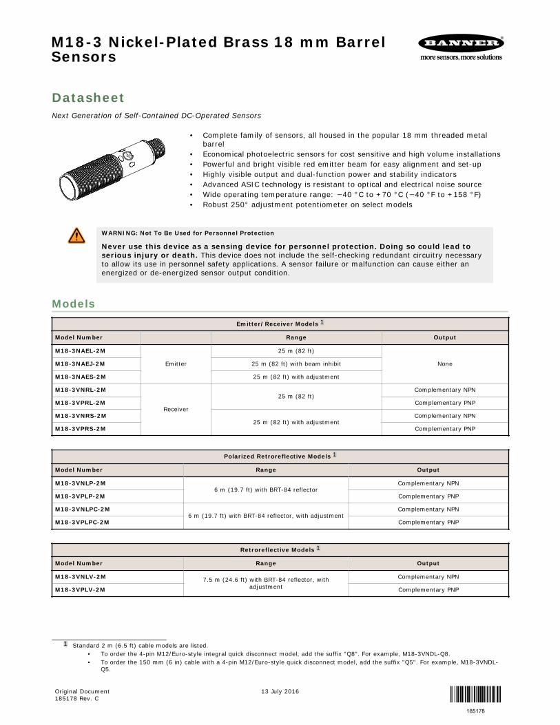
DatasheetNext Generation of Self-Contained DC-Operated Sensors
• Complete family of sensors, all housed in the popular 18 mm threaded metalbarrel
• Economical photoelectric sensors for cost sensitive and high volume installations• Powerful and bright visible red emitter beam for easy alignment and set-up• Highly visible output and dual-function power and stability indicators• Advanced ASIC technology is resistant to optical and electrical noise source• Wide operating temperature range: −40 °C to +70 °C (−40 °F to +158 °F)• Robust 250° adjustment potentiometer on select models
WARNING: Not To Be Used for Personnel Protection
Never use this device as a sensing device for personnel protection. Doing so could lead toserious injury or death. This device does not include the self-checking redundant circuitry necessaryto allow its use in personnel safety applications. A sensor failure or malfunction can cause either anenergized or de-energized sensor output condition.
ModelsEmitter/Receiver Models 1
Model Number Range Output
M18-3NAEL-2M
Emitter
25 m (82 ft)
NoneM18-3NAEJ-2M 25 m (82 ft) with beam inhibit
M18-3NAES-2M 25 m (82 ft) with adjustment
M18-3VNRL-2M
Receiver
25 m (82 ft)Complementary NPN
M18-3VPRL-2M Complementary PNP
M18-3VNRS-2M25 m (82 ft) with adjustment
Complementary NPN
M18-3VPRS-2M Complementary PNP
Polarized Retroreflective Models 1
Model Number Range Output
M18-3VNLP-2M6 m (19.7 ft) with BRT-84 reflector
Complementary NPN
M18-3VPLP-2M Complementary PNP
M18-3VNLPC-2M6 m (19.7 ft) with BRT-84 reflector, with adjustment
Complementary NPN
M18-3VPLPC-2M Complementary PNP
Retroreflective Models 1
Model Number Range Output
M18-3VNLV-2M 7.5 m (24.6 ft) with BRT-84 reflector, withadjustment
Complementary NPN
M18-3VPLV-2M Complementary PNP
1 Standard 2 m (6.5 ft) cable models are listed.• To order the 4-pin M12/Euro-style integral quick disconnect model, add the suffix "Q8". For example, M18-3VNDL-Q8.• To order the 150 mm (6 in) cable with a 4-pin M12/Euro-style quick disconnect model, add the suffix "Q5". For example, M18-3VNDL-
Q5.
M18-3 Nickel-Plated Brass 18 mm BarrelSensors
Original Document185178 Rev. C
13 July 2016
185178
Diffuse Models 1
Model Number Range Output
M18-3VNDL-2M750 mm (29.5 in) with adjustment
Complementary NPN
M18-3VPDL-2M Complementary PNP
M18-3VNDS-2M300 mm (11.8 in) with adjustment
Complementary NPN
M18-3VPDS-2M Complementary PNP
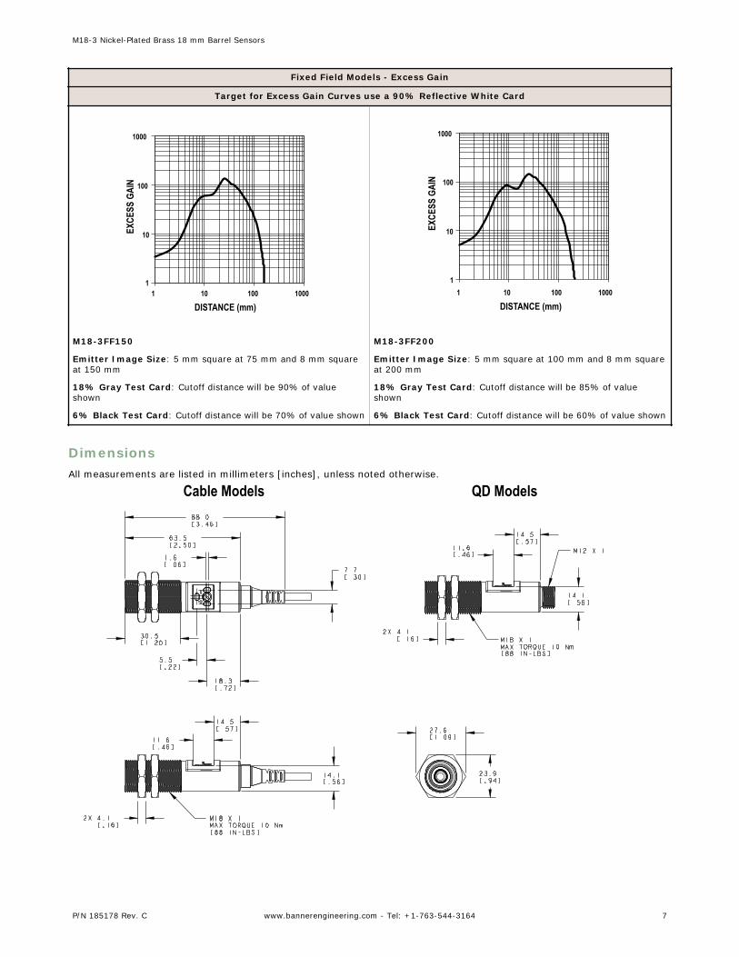
Fixed-Field Models 1
Model Number Range Output
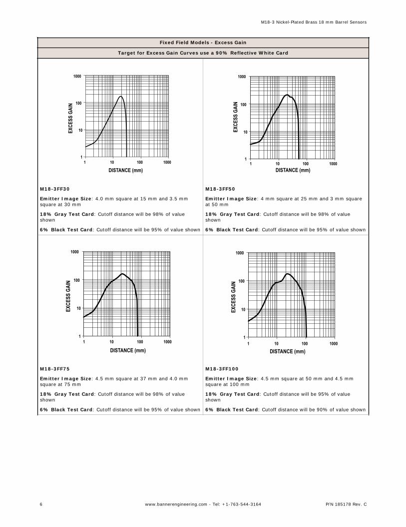
M18-3VNFF30-2M30 mm (1.2 in)
Complementary NPN
M18-3VPFF30-2M Complementary PNP
M18-3VNFF50-2M50 mm (1.9 in)
Complementary NPN
M18-3VPFF50-2M Complementary PNP
M18-3VNFF75-2M75 mm (2.9 in)
Complementary NPN
M18-3VPFF75-2M Complementary PNP
M18-3VNFF100-2M100 mm (3.9 in)
Complementary NPN
M18-3VPFF100-2M Complementary PNP
M18-3VNFF150-2M150 mm (5.9 in)
Complementary NPN
M18-3VPFF150-2M Complementary PNP
M18-3VNFF200-2M200 mm (7.8 in)
Complementary NPN
M18-3VPFF200-2M Complementary PNP
Installing the M18-3 Sensor
Amber LED
Amber LEDGreen LED
Gain adjustment
Figure 1. M18-3 Features and Installation
To install the M18-3 Sensor:
1. Align the sensor as required for theapplication. For the most sensitive objectdetection, align the sensor so that theobjects move across the sensor's axis.
2. Secure the sensor to a bracket.3. Wire sensor as shown in the wiring
diagrams.4. Adjust the gain adjuster (sensitivity pot) if
necessary.
Wiring Diagrams
Emitter Emitter with Active High Beam Inhibit
10-30V dc
–
+1
3 10–30 V dc−
+1
3
4 10–30 V dc
M18-3 Nickel-Plated Brass 18 mm Barrel Sensors
2 www.bannerengineering.com - Tel: +1-763-544-3164 P/N 185178 Rev. C
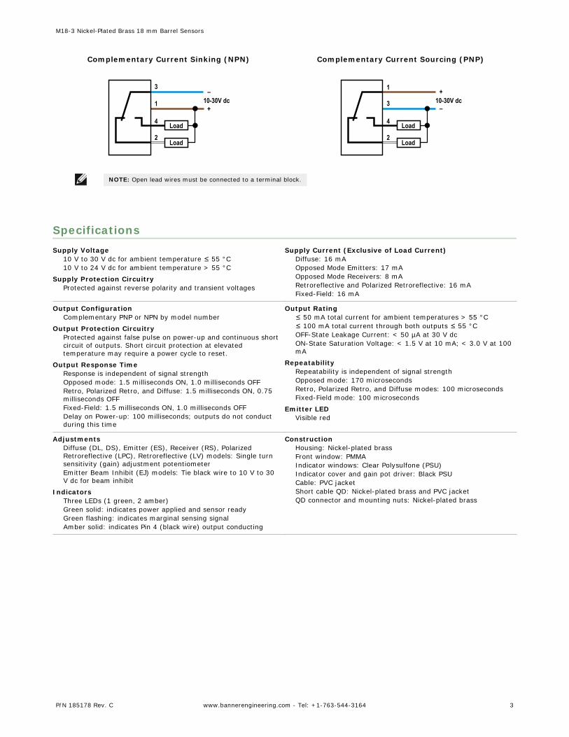
Complementary Current Sinking (NPN) Complementary Current Sourcing (PNP)
10-30V dc–
+1
3
2
4 Load
Load
10-30V dc–
+1
3
2
4 Load
Load
NOTE: Open lead wires must be connected to a terminal block.
SpecificationsSupply Voltage
10 V to 30 V dc for ambient temperature ≤ 55 °C10 V to 24 V dc for ambient temperature > 55 °C
Supply Protection CircuitryProtected against reverse polarity and transient voltages
Supply Current (Exclusive of Load Current)Diffuse: 16 mAOpposed Mode Emitters: 17 mAOpposed Mode Receivers: 8 mARetroreflective and Polarized Retroreflective: 16 mAFixed-Field: 16 mA
Output ConfigurationComplementary PNP or NPN by model number
Output Protection CircuitryProtected against false pulse on power-up and continuous shortcircuit of outputs. Short circuit protection at elevatedtemperature may require a power cycle to reset.
Output Response TimeResponse is independent of signal strengthOpposed mode: 1.5 milliseconds ON, 1.0 milliseconds OFFRetro, Polarized Retro, and Diffuse: 1.5 milliseconds ON, 0.75milliseconds OFFFixed-Field: 1.5 milliseconds ON, 1.0 milliseconds OFFDelay on Power-up: 100 milliseconds; outputs do not conductduring this time
Output Rating≤ 50 mA total current for ambient temperatures > 55 °C≤ 100 mA total current through both outputs ≤ 55 °COFF-State Leakage Current: < 50 µA at 30 V dcON-State Saturation Voltage: < 1.5 V at 10 mA; < 3.0 V at 100mA
RepeatabilityRepeatability is independent of signal strengthOpposed mode: 170 microsecondsRetro, Polarized Retro, and Diffuse modes: 100 microsecondsFixed-Field mode: 100 microseconds
Emitter LEDVisible red
AdjustmentsDiffuse (DL, DS), Emitter (ES), Receiver (RS), PolarizedRetroreflective (LPC), Retroreflective (LV) models: Single turnsensitivity (gain) adjustment potentiometerEmitter Beam Inhibit (EJ) models: Tie black wire to 10 V to 30V dc for beam inhibit
ConstructionHousing: Nickel-plated brassFront window: PMMAIndicator windows: Clear Polysulfone (PSU)Indicator cover and gain pot driver: Black PSUCable: PVC jacketShort cable QD: Nickel-plated brass and PVC jacketQD connector and mounting nuts: Nickel-plated brass
M18-3 Nickel-Plated Brass 18 mm Barrel Sensors
P/N 185178 Rev. C www.bannerengineering.com - Tel: +1-763-544-3164 3
Operating ConditionsTemperature: −40 °C to +70 °C (−40 °F to +158 °F)95% at +50 °C maximum relative humidity (non-condensing)
Environmental RatingIEC 60529 IP67 and IP69K
Vibration and Mechanical ShockAll models meet Mil. Std. 202F requirements. Method 201A(Vibration; frequency 10 to 60 Hz, max., double amplitude 0.06in acceleration 10G). Method 213B conditions H&I (Shock: 75Gwith unit operating; 100G for non-operation)
Certifications
IndustrialControlEquipment
3TJJ
Class 2 power
UL Environmental Rating: Type 1
Required Overcurrent Protection
WARNING: Electrical connectionsmust be made by qualified personnel inaccordance with local and nationalelectrical codes and regulations.
Overcurrent protection is required to be provided by endproduct application per the supplied table.Overcurrent protection may be provided with external fusing orvia Current Limiting, Class 2 Power Supply.Supply wiring leads < 24 AWG shall not be spliced.For additional product support, go to http://www.bannerengineering.com.
AP18SCN 3 Kit includes round apertures of 0.5 mm (0.02 in), 1.0 mm (0.04in), and 2.5 mm (0.10 in) diameter.
AP18SRN 3Kit includes rectangular apertures of 0.5 mm (0.02 in), 1.0 mm(0.04 in), and 2.5 mm (0.10 in) wide. Each kit also includes athread-on housing, Teflon® FEP® lens, and o-ring.
APG18S 1 Kit with glass lens to protect plastic sensor lens from chemicalenvironments and weld splatter damage.
M18-3 Nickel-Plated Brass 18 mm Barrel Sensors
8 www.bannerengineering.com - Tel: +1-763-544-3164 P/N 185178 Rev. C
Brackets
SMB18SF• 18 mm swivel bracket
with M18 × 1 internalthread
• Black thermoplasticpolyester
• Stainless steel swivellocking hardwareincluded
B
A
51
42
25
Hole center spacing: A = 36.0Hole size: A = ø 5.3, B = ø 18.0
SMBS18-2-1• 30% glass-filled PBT
M18 - 1 x 6G
4.5ø28
SMB18A• Right-angle mounting
bracket with a curvedslot for versatileorientation
• 12-ga. stainless steel• 18 mm sensor
mounting hole• Clearance for M4 (#8)
hardware
30
41
46
A BC
Hole center spacing: A to B = 24.2Hole size: A = ø 4.6, B = 17.0 × 4.6, C = ø 18.5
SMB18FA..• Swivel bracket with tilt
and pan movement forprecision adjustment
• Easy sensor mounting toextruded rail T-slots
• Metric and inch size boltsavailable
• 18 mm sensor mountinghole
66
69A
B
Hole size: B=ø 18.1
Model Bolt Thread (A)
SMB18FA 3/8 - 16 × 2 in
SMB18FAM10 M10 - 1.5 × 50
SMB18FAM12 n/a; no bolt included.Mounts directly to 12 mm(½ in) rods
For additional brackets, check the current Banner catalog or visit www.bannerengineering.com. All measurements arelisted in millimeters, unless noted otherwise.
(+122 ºF)• Optional brackets are available• Approximate size: 51 mm × 51
mm
BRT-84X84A
• Square, acrylic target• Reflectivity Factor: 2.0• Temperature: −20 °C to +60 °C
(−4 °F to +140 °F)• Approximate size: 84 mm × 84
mm
M18-3 Nickel-Plated Brass 18 mm Barrel Sensors
P/N 185178 Rev. C www.bannerengineering.com - Tel: +1-763-544-3164 9
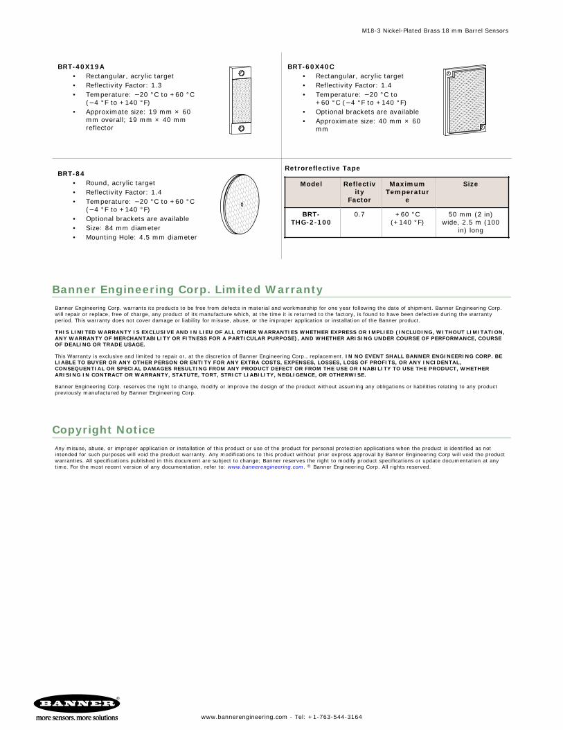
BRT-40X19A• Rectangular, acrylic target• Reflectivity Factor: 1.3• Temperature: −20 °C to +60 °C
(−4 °F to +140 °F)• Approximate size: 19 mm × 60
mm overall; 19 mm × 40 mmreflector
BRT-60X40C• Rectangular, acrylic target• Reflectivity Factor: 1.4• Temperature: −20 °C to
+60 °C (−4 °F to +140 °F)• Optional brackets are available• Approximate size: 40 mm × 60
mm
BRT-84• Round, acrylic target• Reflectivity Factor: 1.4• Temperature: −20 °C to +60 °C
(−4 °F to +140 °F)• Optional brackets are available• Size: 84 mm diameter• Mounting Hole: 4.5 mm diameter
Retroreflective Tape
Model Reflectivity
Factor
MaximumTemperatur
e
Size
BRT-THG-2-100
0.7 +60 °C(+140 °F)
50 mm (2 in)wide, 2.5 m (100
in) long
Banner Engineering Corp. Limited WarrantyBanner Engineering Corp. warrants its products to be free from defects in material and workmanship for one year following the date of shipment. Banner Engineering Corp.will repair or replace, free of charge, any product of its manufacture which, at the time it is returned to the factory, is found to have been defective during the warrantyperiod. This warranty does not cover damage or liability for misuse, abuse, or the improper application or installation of the Banner product.
THIS LIMITED WARRANTY IS EXCLUSIVE AND IN LIEU OF ALL OTHER WARRANTIES WHETHER EXPRESS OR IMPLIED (INCLUDING, WITHOUT LIMITATION,ANY WARRANTY OF MERCHANTABILITY OR FITNESS FOR A PARTICULAR PURPOSE), AND WHETHER ARISING UNDER COURSE OF PERFORMANCE, COURSEOF DEALING OR TRADE USAGE.
This Warranty is exclusive and limited to repair or, at the discretion of Banner Engineering Corp., replacement. IN NO EVENT SHALL BANNER ENGINEERING CORP. BELIABLE TO BUYER OR ANY OTHER PERSON OR ENTITY FOR ANY EXTRA COSTS, EXPENSES, LOSSES, LOSS OF PROFITS, OR ANY INCIDENTAL,CONSEQUENTIAL OR SPECIAL DAMAGES RESULTING FROM ANY PRODUCT DEFECT OR FROM THE USE OR INABILITY TO USE THE PRODUCT, WHETHERARISING IN CONTRACT OR WARRANTY, STATUTE, TORT, STRICT LIABILITY, NEGLIGENCE, OR OTHERWISE.
Banner Engineering Corp. reserves the right to change, modify or improve the design of the product without assuming any obligations or liabilities relating to any productpreviously manufactured by Banner Engineering Corp.