1 ! For your protection and the safety of the product user, please comply with all Caution and Warning statements within this document. All installation practices must comply with all applicable national and/or local electrical and building codes and be performed by qualified personnel only. Introduction e metal or plastic pedestal-mount satellite controller unit is designed for installation on a substantial concrete pad with embedded conduit of various diameters to enable wiring connections for power, field, earth ground, sensor and optional external antenna. Pedestal anchor bolts and a steel bolt pattern template are supplied with the controller. e wall-mount satellite unit is designed for installation on a structurally-sound building wall. e stainless steel cabinet is moisture resistant and suitable for outdoor installation. e cabinet has upper and lower support attachments and is supplied with a mounting bracket which attaches directly to the wall. Refer to wall mount installation procedures below for the Small Cabinet Wallmount (WS1) or to page 5 for the Large Cabinet Wallmount (WS5). Additional materials required to complete the installation must be obtained separately. A material list can be compiled by reading through the instructions completely prior to starting the installation. Sentinel ® AC 2-Wire Controller Installation Instructions Sentinel ® AC 2-Wire Controller Installation Instructions Introduction 1 Installation 2 Small Cabinet Wallmount (WS1) 2 Stainless Steel Pedestal (PS1) 3 Plastic Pedestal (PP1, PP2, PP3) 4 Large Stainless Steel Wallmount (WS5) 5 Earth Ground Installation 6 Wire Connections 7 Power Source Installation 7 Grounding the Communication Cable 8 Station Decoder Installation 9 Alarm and Sensor Connections 11 Specifications 12 Toro Warranty and Dedication to Quality 13 FCC Statement 13 Table of Contents
Transcript
1
! For your protection and the safety of the product user, please comply with all Caution and Warning statements within this document. All installation practices must comply with all applicable national and/or local electrical and building codes and be performed by qualified personnel only.
IntroductionThe metal or plastic pedestal-mount satellite controller unit is designed for installation on a substantial concrete pad with embedded conduit of various diameters to enable wiring connections for power, field, earth ground, sensor and optional external antenna. Pedestal anchor bolts and a steel bolt pattern template are supplied with the controller.The wall-mount satellite unit is designed for installation on a structurally-sound building wall. The stainless steel cabinet is moisture resistant and suitable for outdoor installation. The cabinet has upper and lower support attachments and is supplied with a mounting bracket which attaches directly to the wall. Refer to wall mount installation procedures below for the Small Cabinet Wallmount (WS1) or to page 5 for the Large Cabinet Wallmount (WS5).Additional materials required to complete the installation must be obtained separately. A material list can be compiled by reading through the instructions completely prior to starting the installation.
Sentinel® AC 2-Wire ControllerInstallation InstructionsSentinel® AC 2-Wire ControllerInstallation Instructions
Wire Connections 7 Power Source Installation 7 Grounding the Communication Cable 8 Station Decoder Installation 9 Alarm and Sensor Connections 11Specifications 12Toro Warranty and Dedication to Quality 13FCC Statement 13
Table of Contents
2
Controller Installation
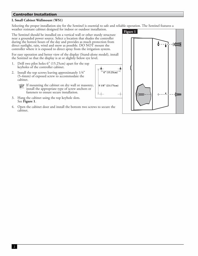
I. Small Cabinet Wallmount (WS1)
Selecting the proper installation site for the Sentinel is essential to safe and reliable operation. The Sentinel features a weather resistant cabinet designed for indoor or outdoor installation.The Sentinel should be installed on a vertical wall or other sturdy structure near a grounded power source. Select a location that shades the controller during the hottest hours of the day and provides as much protection from direct sunlight, rain, wind and snow as possible. DO NOT mount the controller where it is exposed to direct spray from the irrigation system.For easy operation and better view of the display (Stand-alone model), install the Sentinel so that the display is at or slightly below eye level.1. Drill two pilot holes 6” (15.25cm) apart for the top
keyholes of the controller cabinet.2. Install the top screws leaving approximately 1/4”
(5–6mm) of exposed screw to accommodate the cabinet.
If mounting the cabinet on dry wall or masonry, install the appropriate type of screw anchors or fasteners to ensure secure installation.
3. Hang the cabinet using the top keyhole slots. See Figure 1.
4. Open the cabinet door and install the bottom two screws to secure the cabinet.
6" (15.25cm)
9 1/8" (23.175cm)
Figure 1
3
II. Stainless Steel Pedestal (PS1)
1. Prepare a hole for the pad and wiring conduit using the minimum recommended dimensions shown in Figure 2. This size pad requires approximately 4 cu ft (122cu cm) of concrete.
2. Position straight and sweep elbow conduit sections in foundation hole as shown. Placing the controller toward the back of the pad as shown protects the ground near the front of the controller from wear.
3. Tape the conduit ends to seal out dirt. Backfill soil to form a 6” (15cm) foundation depth. The conduit should not extend more than 2” (51mm) above the finished top surface of the foundation.
4. Form the perimeter of the pad area using 2 x 6 boards or 3/4” (19mm) plywood.
5. Prepare the mounting bolt template with the provided L-shaped bolts and hex nuts as shown in Figure 2.
6. Pour concrete into the formed area and trowel smooth. Finish the concrete pad with a level flat area for the pedestal base approximately 8” x 17” (20cm x 43cm).
7. Aligning the mounting bolt template with the conduit, press the L-shaped bolts into the concrete until the template makes contact. To prevent pooling at the base of the pedestal, add a slight taper away from the template. Allow the concrete to sufficiently harden before continuing.
8. Remove the mounting bolt hex nuts. Remove and discard the mounting bolt template. Place the pedestal on the pad ensuring all bolts are inserted into the pedestal base. Install a flat washer and a hex nut on each bolt and tighten securely.
* Refer to local electrical codes for the required wire burial depth.
Figure 2 Wood Form
6” (15.2mm)
Mounting Bolt Template - Cabinet Base Area 8” x 17” (20.3cm x 43.2cm)
1/2” (13mm) Conduit for Earth Ground
3/4” (20mm) Conduit for Input Power Wiring
2” (50mm) Conduit for Field Wiring
1 1/4” (32mm) Conduit for External Antenna Cable
(Optional)
2” (50mm) Conduit for Field Wiring
1/2” (15mm) Conduit for Sensor Wires (Optional)
36” (91cm)
29” (73.7cm)
Mounting Bolt Template
Mounting Bolts w/Hex Nuts (Typical Four Places)
2” (51mm)
6” (15cm)
Taper
See *
4-20
GN
D
BLK BLKRED REDBLK BLKRED RED
ONOFF
AUTOCOM
AUX2
AUX1
COM
PMP
MV
ASENTINEL®
ENTER
Home/Back
D
ANTINEL®
Option
4
III. Plastic Pedestal (PP1, PP2, PP3)
1. Prepare a hole for the foundation and wiring conduit using the minimum recommended dimensions shown in Figure 3.
2. Trench to the foundation site as required for each wiring run.
3. Position straight and sweep elbow conduit sections in foundation hole as shown. Tape the conduit ends to seal out dirt. Backfill soil to form a 6” (15.2cm) foundation depth. Conduit should not extend more than 2” (51mm) above the finished top surface of the foundation.
4. Prepare the sides of the foundation hole with wood forms.
5. Prepare the mounting bolt positioner with the 5/16 x 4-1/2” bolts and nuts (provided) as shown in Figure 3. The threads should extend 2” (51mm) from the top surface of the bolt positioner.
6. Pour concrete into the formed foundation hole. Press the mounting bolt positioner into the concrete until it is flush and level with the foundation surface and aligned with the conduit.
7. Finish the concrete with a level flat area of 16” x 16” (41cm x 41cm) for the pedestal base. To prevent pooling at the base of the pedestal, add a slight taper away from the cabinet base contact area. Allow concrete to sufficiently harden before continuing.
8. Remove the hex nuts from the mounting studs. Remove the cabinet cover and doors. Carefully position the controller onto the studs. Install a flat washer and a hex nut on each stud and tighten securely.
* Refer to local electrical codes for required wire burial depth.
Wood Form
Plastic Cabinet Base Area
4” (10cm) - Field Wiring
Conduit Recommendations
1 1/2” (40mm) - External Antenna (Optional)
3/4” (20mm) - Earth Ground
3/4” (20mm) - Power Supply
30” (76cm)
2” (50mm) Maximum
30” (76cm)
Taper
See *
6” (15cm)
Mounting Bolt Positioner
2” (50mm)
Figure 3
5
IV. Large Stainless Steel Wallmount (WS5)
1. Position the upper support bracket on the wall with the joggle edge up to accept the mating upper cabinet bracket (Figure 4). The support bracket must be level and at a height approximately 2” (51mm) above eye level to enable the Sentinel control module display to be easily viewed.
2. Mark the two mounting screw hole locations and drill pilot holes for the screws or screw anchors. Use 3/8” (10mm) diameter fasteners to attach
the cabinet support brackets. If installing the cabinet on dry wall or masonry, install the appropriate size and type screw anchors.
3. Secure the support bracket to the wall. Hang the cabinet on the wall by engaging the upper cabinet bracket and the support bracket.
4. Draw a pencil line the entire length of the lower support bracket.
5. Remove the cabinet from the wall and remove the lower support bracket from the cabinet.
6. Place the lower support bracket on the wall aligning it with the pencil mark.
7. Mark the two screw hole locations and drill pilot holes for the mounting screws or screw anchors.
8. Secure the bottom support bracket to the wall.9. Remove optional conduit knock-outs as required
for installation. See * below.
10. Hang the cabinet on the wall mount support bracket. The bottom edge of the cabinet should now rest squarely on the lower support bracket.
11. Secure the cabinet to the lower support bracket using the carriage bolts and nuts removed in Step 5 above.
12. Install electrical conduit for all wiring connections per local and national code. See Figure 5.
* On early model cabinets, conduit access holes are only provided for power and one field wire conduit. Additional conduit access holes for earth ground, additional field wire conduit, optional sensor wires and optional external antenna must be cut or punched by the installer. All conduit access holes and knock-outs are provided on current production cabinets.
BLK BLKRED REDBLK BLKRED RED
ONOFF
AUTOCOM
AUX2
AUX1
COM
PMP
M V
ALRM1
ALRM2
FLOW1
FLOW2
ALM GND
FL GND
+12V
4-20
4-20 GND
AlarmBA
Hold IrrigationSENTINEL®
ENTER
Home/Back ManualWatering
ScheduledWatering
Diagnostics& Alarms
Station Settings
Satellite SettingsStopHelpStart
AlarmB
Hold Irrigation
Option
Upper Cabinet Bracket
Upper Support Bracket
Screw Anchors
Lower Support Bracket
3/4” (20mm) Conduit for Power Wires
2” (50mm) Conduit for Field Wiring
1/2” (15mm) Conduit for Earth Ground
1 1/2” (40mm) Conduit for External Antenna (Optional)
2” (50mm) Conduit for Field Wiring
1/2” (15mm) Conduit for
Sensor Wires (Optional)
Figure 4
Figure 5
6
V. Earth Ground Installation
IMPORTANT! The Sentinel 2-Wire surge protection components cannot properly function unless an efficient pathway to earth ground is provided. The ground path must be as direct as possible, without sharp bends and must not exceed 30 Ohm resistance (when measured with an earth ground resistance device). All electrical components throughout the irrigation system should be grounded similarly to provide the same ground potential. The following instructions depict one of several acceptable earth grounding methods. Due to variables in soil composition and terrain, the method shown may not be suitable for your installation site. Contact your local Toro distributor for assistance and availability of the required earth ground resistance test instrument.1. Drive a 5/8” x 8’ (17mm x 2.5m) copper-clad steel rod into well moistened soil not less than 8’ (2.5m) or not more
than 12’ (3.7m) from the controller cabinet. The top of the ground rod should be flush with or below ground level, and should be protected from damage using a valve box. See Figure 2.
2. Using a 5/8” (17mm) clamp or “Cad weld” fastener, attach an 8 AWG (8mm2) solid copper wire near the top of the ground rod. Avoiding wire bends of less than 8” (20.3cm) radius and more than 90º, route the wire through conduit and into the cabinet. Secure the wire to the copper ground lug. Make sure the soil surrounding the ground rod(s) remains well moistened at all times. The addition of some form of
irrigation may be required if the cabinet is installed in a non-irrigated location.3. Measure the ground resistance per the instructions provided with the ground test instrument. A reading of 10 or less is
preferred, 10-20 is acceptable, 20-30 is marginal, and 30+ should be improved.. If the resistance exceeds the acceptable limit, additional ground rod(s) can be installed at a distance equal to twice the buried depth of the first rod; i.e., 16’ (4.9m) . Interconnect the ground rods using 8 AWG (8mm2) solid copper wire and test again. If the measured ground resistance continues to read above the acceptable limit, contact your local Toro distributor for further assistance and recommendations. Installing a round valve box over the ground rod enables the ground rod to be easily located as well as providing access
to the ground wire connection(s).
Ground Lug
Valve Box
8 AWG (8mm2) Solid Copper Ground Wire
Copper Clad Ground Rod
Ground Wire To Additional Rod(s) (Optional) 8'–12'
(2.4m – 3.7m)
8" (20.3cm) Minimum Radius
90o Minimum Angle
Figure 6
7
Wire Connections
I. Power Source Installation
Caution: When installing multiple controllers, polarity of the Line and Neutral connections must be properly maintained throughout the irrigation system. Reversed polarity may cause damaging potentials to exist at one or more controller locations. An equipment ground wire from the power source must be connected to each satellite controller.
WARNINGAC power wiring must be installed and connected by qualified personnel only.All electrical components and installation procedures must comply with all applicable local and national electrical codes. Some codes may require a means of disconnection from the AC power source, installed in the fixed wiring, having a contact separation of at least 0.120” in the line and neutral poles.The wire used for connection to the controller must have insulation rated at 105°C minimum.Ensure the AC power source is OFF prior to servicing or connecting to the controller.
1. Turn off the power at the power source location and place the controller’s power switch to OFF. Connect and route the appropriate size 3-conductor cable (14 AWG [2.5mm2] maximum) from the power source to the controller cabinet. The provided power cable access hole can accommodate a 1” (25mm) conduit fitting. If conduit is required, install a section of flexible 1” (25mm) electrical conduit from the power source conduit box to the cabinet’s access hole.
2. Open the cabinet door and remove the two retaining screws from the power supply cover.3. Strip the power cables and secure them to the terminal block. Reference Table 1 for the appropriate type of power
connection. 4. Reinstall the power supply cover.5. Apply power to the controller.
equipmentground
lineneutral
Figure 7
See Table 1
8
II. Grounding the Communication Cable
The lightning arrester (Toro P/N SB-BLA) is required to protect the decoder module from lightning. Without lightning arresters, the decoders are vulnerable to lightning damage. In order for these arresters to discharge lightning energy efficiently, they must be properly grounded. To be effective, a resistance of 10 Ohms or less must be achieved at each earth ground point. Figure 8 illustrates the proper grounding and wiring of the arrester.1. Locate decoder’s power/communication wires (black and white wires). 2. Strip the insulation from lightning arrester’s white wire and connect it to the white wires from the decoder and controller-
to-decoder cable. Use 3M DBR/Y products to properly water-proof all wire connections (Figure 8, Detail A).3. Strip the insulation from lightning arrester’s black wire and connect it to the black wires from the decoder and controller-
to-decoder cable. Use 3M DBR/Y products to properly water-proof all wire connections (Figure 8, Detail A).4. Connect the lightning arrester’s ground wire to the ground rod or plate’s wire. If the ground rod or plate is not pre-
wired, use a 10 AWG bare copper wire (Figure 8).
! If using a ground rod, verify that the straight line distance between the lightning arrester/decoders and the ground rod is 8' (2.5m) +/– 10%. If using a 3' (1m) ground plate, the straight line distance should be 3' (1m) +/– 10%.
5. If necessary, use ground enhancement material (GEM) to attain a resistance of 10 Ohms or less.6. Check the system for proper operation.
Figure 8
600'
Maximum of 600' of communication line between lightning arresters and no more than 600’ from a decoder to a surge device.
It is not recommended that a surge device be installed in the wire if the run from the controller to the first decoder is over 600 feet. In this application, the surge device should be installed at the first decoder on this run.
See Detail A
Detail A
Lightning Arrester Toro P/N SB-BLA
Toro AC Decoder Module
8'
Ensure a maximum of 10 Ohms resistance for each earth ground.
8' (2.5m) (+/– 10%) between the arrester and the ground rod or 3' (1m) (+/– 10%) distance between arrestor and ground plate.
9
III. Station Decoder Installation
The station decoder module is available in 1-station, 2-station, or 4-station configurations.
The stand-alone Sentinel 2-Wire model can handle up to 204 stations. The decoder modules can be connected in parallel anywhere on the two-wire communication line connected to the station terminals. Each station can activate two standard solenoids.
It is recommended that the decoder modules are installed in an approved valve box to provide easy access to the wiring. Use of 3M DBR/Y (or an equivalent grease cap) to waterproof all connectors is required.
Recommended Controller-to-Decoder cable: 14 AWG (2.5mm2), solid copper, jacketed 2-conductor, direct burial. The preferred wire make and model is the Paige Irrigation Wire, Spec P7350D.
Recommended Decoder-to-Solenoid cable: 14 AWG (2.5mm2), solid copper, 2-conductor, direct burial. The preferred wire make and model is the Paige Irrigation Wire, Spec P7351D.
Burial DepthToro recommends that the Controller-to-Decoder and Decoder-to-Solenoid cables should have a minimum cover of 6" (150mm). The irrigation plan may specify additional depth to be consistent with the depth of mainline or lateral pipe work and/or soil conditioning procedures such as aeration. Installation procedures must comply with all applicable local and national electrical codes.
• Use only wire approved for direct burial if installing the wires underground without conduit. • All field wiring splices must be accessible to facilitate troubleshooting and/or service.
1. Route communication cable from the controller to the station decoder module installation location.
The maximum wire length between the controller and the decoder module is 5,000' or 10,000 with looped path.
2. Secure the communication wires to Terminal 1 of the Sentinel 2-Wire output board. Red wire onto the 1st terminal and black wire onto the second terminal. See Figure 9.
3. Install the decoder module in a valve box. Record the decoder module’s address number found on the label. This address number identifies the station(s) that the decoder module controls.
4. Secure the communication wires to the decoder module’s black and white wires. Connect the black communication wire to the black decoder module wire. Connect the remaining communication wire (red or white) to the white decoder module wire. Use 3M DBR/Y to properly water-proof all wire connections.
5. Route output wires from the decoder module to the solenoid.
The maximum wire length between the decoder module and the solenoid is 150' (45.7m).
6. Connect the solenoid wires to the decoder module’s station wires. The station wires are color coded for easy identification. Connect the solid colored (red, green, orange or blue) station wire to the red/white solenoid wire. Connect the similar color station wire with black stripe to the black solenoid wire. Use 3M DBR/Y to properly water-proof all wire connections.
7. Repeat Steps 3–6 for additional decoder modules.
10
ONOFF
AUTO
PMP
MV
MP
VBLK BLKRED RED
BLK BLKRED REDLK RERE
Valve Box
Maximum communication wire length between the controller
and the farthest decoder: straight line 14 AWG: 5,000' (1,524 m)
looped 14 AWG: 10,000’ (3,048 m)straight line 12 AWG: 8,000’ (2438 m)
looped 12 AWG: 16,000’ (4876 m)
The maximum communication wire length between the decoder module and the solenoid is 150' (45.7 m).Required cable for Decoder-to-Solenoid is 14 AWG, Solid Copper, 2-Conductor, Direct Burial cable.To easily identify stations for troubleshooting, install wires with the same color code as the station wires.
Output Board
SENTINELDECODER (SB-DAC-4)CONTROLLER:
STATION:
COMM
V-4
V-3
V-2
V-1
SENTR (SB
OLLE
N:
SDECODERCONTRO
STATION
Red Power/Communication Wire Black Power/Communication Wireto 2-Wire Output Board
Common wire
V-1 hot wire
V-2 hot wire
V-3 hot wire
V-4 hot wire
Figure 9
Decoder modules are required to be installed in a valve box for ease of service.
Required cable for Controller-to-Decoder is 14 AWG, Solid Copper, Jacketed 2-Conductor, Direct Burial cable.
Use of metal conduit is not necessary for most installations, but is recommended in sharp rocky soil conditions, if required by local codes, or if the installation lay-out will not allow the separation of high voltage wiring from the decoder cable by the 1 foot per 100 Volt recommendation.
The decoder label indicates the locations for the hot wires to their respective valve numbers and the common wire. For example, the “V-1” wire is the hot wire for valve number 1, “V-2” is the hot wire for valve number 2, etc. On the label, write the controller number in the “controller” field, the unique decoder ID of your choice in the “station” field, and optionally, any notes in the blank field at the bottom.
For information on how to program decoder addresses into the controller, please refer to the Sentinel Programming Guide (373-0759) at www.toro.com/sentinel.
11
IV. Alarm and Sensor Connections
The Alarm Switch is designed to monitor a dry contact switch and the alarm functionality is programmable in the system software. The Alarm Switch input can be programmed to start or stop programs of your choice and even follow the contact status if desired. The “Flow Signal” is designed to read “shorting pulse output” from a Data Industrial flow meter (or equivalent). If a rain tipping bucket or evapotranspiration (ET) gauge is used, this would to be a normally open contact type. The controller measures the timing of the contact closures to determine if it is a flow pulse, rain pulse or ET pulse. 1. Connect a wire pair to the alarm switch and/or flow measuring device and route into
the controller through 1/2” (15mm) conduit. 2. Connect the wire pair to the appropriate terminals as shown in Figure 10.
Refer to Sentinel Field Satellite Controller User’s Guide for operating instructions.
ALR
M1
ALR
M2
FLO
W1
FLO
W2
ALM
GN
D
FL G
ND
+12V
4-20
4-20
GN
D
Data Retrieval Cable (To Sentinel)
Figure 10
Figure 11Wiring Configurations:
Loop
Straight line
Grid
12
Plastic Pedestal (PP1, PP2, PP3)Key-actuated locking front, back and top covers16” W x 16” D x 43½” H (41cm W x 41cm D x 127cm H)Weight – 70 lbs. (32.8kg)
Stainless Steel Pedestal (PS1)Stainless steel, type UL 3RKey-actuated locking front panel and top control panel cover17 1/8” W x 8 5/8” D x 34½” H (43.5cm W x 22cm D x 88cm H)Weight – 55 lbs. (24.9kg)
Small Cabinet Wallmount (WS1)Key-actuated locking front panel10½” W x 5½” D x 30 15½” H (26.8 cm W x 14.1 cm D x 39.6 cm H)Weight – 19.8 lbs. (9 kg)IP rating for enclosure: 44
Large Stainless Steel Wallmount (WS5)Stainless steel, type UL 3RKey-actuated locking front panel17 1/8” W x 8 5/8” D x 30¾” H (43.5cm W x 22cm D x 78cm H)Weight – 47 lbs. (21.3kg)
Temperature Range:Operating- 14°F to 140°F (-10°C to 60°C)Storage- -22°F to 158°F (-30°C to 70°C)
Power:Input: 120 VAC, 60 HzOutput: Up to two standard solenoids per station Four solenoids per decoder maximum
Fuses:250V, 2.0A Slow-Blow - 24 VAC250V, 2.0A Slow-Blow - Common
Sensor Input:Alarm Switch – Dry contact switchFlow Signal – Normally Open switch
Radio:Radio Equipment used with the Sentinel controller must comply with all applicable national and/or local electrical codes.
Specifications
13
Toro Warranty and Dedication to QualityThe Toro Company and its affiliate, Toro Warranty Company, pursuant to an agreement between them, jointly warrants, to the owner, against defects in material and workmanship for a period of five years from the date of purchase. Neither The Toro Company nor Toro Warranty Company is liable for failure of products not manufactured by them even though such products may be sold or used in conjunction with Toro products. During such warranty period, we will repair or replace, at our option, any part found to be defective. Return the defective part to the place of purchase.Our liability is limited solely to the replacement or repair of defective parts. There are no other express warranties. This warranty does not apply where equipment is used, or installation is performed, in any manner contrary to Toro’s specifications and instructions, nor where equipment is altered or modified. Neither The Toro Company nor Toro Warranty Company is liable for indirect, incidental or consequential damages in connection with the use of equipment, including but not limited to: vegetation loss, the cost of substitute equipment or services required during periods of malfunction or resulting non-use, property damage or personal injury resulting from installer’s negligence.Some states do not allow the exclusion or limitation of incidental or consequential damages, so the above limitation or exclusion may not apply to you. All implied warranties, including those of merchantability and fitness for use, are limited to the duration of this express warranty. Some states do not allow limitations of how long an implied warranty lasts, so the above limitation may not apply to you.This warranty gives you specific legal rights and you may have other rights which vary from state to state. Toro is committed to developing and producing the highest quality, best performing, most dependable products on the market. Because your satisfaction is our first priority, we have provided the Toro Helpline to assist you with any questions or problems that may arise. If for some reason you are not satisfied with your purchase or have questions, please contact your local authorized Toro dealer or e-mail [email protected].
FCC Statement
This equipment has been tested and found to comply with the limits for a Class A digital device, pursuant to part 15 of the FCC Rules. These limits are designed to provide reasonable protection against harmful interference in a residential installation. This equipment generates, uses and can radiate radio frequency energy and, if not installed and used in accordance with the instructions, may cause harmful interference to radio communications. However, there is no guarantee that interference will not occur in a particular installation. If this equipment does cause harmful interference to radio or television reception, which can be determined by turning the equipment off and on, the user is encouraged to try to correct the interference by one or more of the following measures:• Reorient or relocate the receiving antenna.• Increase the separation between the equipment and receiver.• Connect the equipment into an outlet on a circuit different from that to which the receiver is connected.• Consult the dealer or an experienced radio/TV technician for help.If necessary, the user should consult the dealer or an experienced radio/television technician for additional suggestions. The user may find the following booklet prepared by the Federal Communications Commission helpful: “How to Identify and Resolve Radio-TV Interference Problems.” This booklet is available from the U.S. Government Printing Office, Washington, D.C., Stock No. 004-000-00345-4 (price – $2.00 postpaid).
International: This is a CISPR 22 Class A product. In a domestic environment, this product may cause radio interference, in which case the user may be required to take adequate measures. Each stations can activate up to two solenoids.This product, utilizing a Class 2 transformer tested to UL1585, satisfies the requirements of a Class 2 Power Source as defined in the NFPA 70 (NEC), Article 725.121(A)(3).