141
SENTRY (Includes Scout Controls) OPERATIONS MANUAL ERIE STRAYER COMPANY. Founded 1912. Phone: 814-456-7001 Fax: 814-456-3422 E-mail: [email protected]

SENTRY(Includes Scout Controls) OPERATIONS MANUAL
ERIE STRAYER COMPANY.Founded 1912.
Phone: 8144567001Fax: 8144563422Email: [email protected]

Revision: 1.50DATE: November 12, 2001
copyright 01/01/2000
Table of Contents:
1 INTRODUCTION . . . . . . . . . . . . . . . . . . . . . . . 1
2 SYSTEM OVERVIEW . . . . . . . . . . . . . . . . . . . . . 3 2.1 Sentry Computer System . . . . . . . . . . . . . . . . . . . . 3 2.2 Combination Manual Control Panel and Computer Interface . . . . . 32.3 Load Cell Indicator . . . . . . . . . . . . . . . . . . . . . . . 42.4 Printer . . . . . . . . . . . . . . . . . . . . . . . . . . . . . 4
3 AUTOMATIC SYSTEM OPERATION . . . . . . . . . . . . . . 53.1 System Startup . . . . . . . . . . . . . . . . . . . . . . . 53.2 Batch Operation Program . . . . . . . . . . . . . . . . . . . . 53.3 Main Menu . . . . . . . . . . . . . . . . . . . . . . . . . . 6 3.4 MultiTasking feature “ The F12 Key” . . . . . . . . . . . . . . 7
4 YARDAGE CALCULATOR (F2) . . . . . . . . . . . . . . . . 9
5 ORDER ENTRY (F4) . . . . . . . . . . . . . . . . . . . . . 11 5.1 Adding a New Job . . . . . . . . . . . . . . . . . . . . . . . 115.2 Modifying a Record (Edit or View) . . . . . . . . . . . . . . . . . 12
5.2.1 Deliver To . . . . . . . . . . . . . . . . . . . . . . . 125.2.2 Order Date . . . . . . . . . . . . . . . . . . . . . . . 135.2.3 Delivery Date . . . . . . . . . . . . . . . . . . . . . . . 135.2.4 Quantity Ordered . . . . . . . . . . . . . . . . . . . . 135.2.5 Quantity Delivered . . . . . . . . . . . . . . . . . . . . 145.2.6 Loads Delivered . . . . . . . . . . . . . . . . . . . . 145.2.7 Batch Size . . . . . . . . . . . . . . . . . . . . . . . 145.2.8 Mix . . . . . . . . . . . . . . . . . . . . . . . . . . 145.2.9 Job Use . . . . . . . . . . . . . . . . . . . . . . . 145.2.10 Print Weights? . . . . . . . . . . . . . . . . . . . . 145.2.11 Pricing Data . . . . . . . . . . . . . . . . . . . . 15
5.3 Delete a Record . . . . . . . . . . . . . . . . . . . . . . . 155.4 Search . . . . . . . . . . . . . . . . . . . . . . . . . . . . . 155.5 Export . . . . . . . . . . . . . . . . . . . . . . . . . . 155.6 Zero Jobs . . . . . . . . . . . . . . . . . . . . . . . . . . 16
6 FILE SYSTEM (F5) . . . . . . . . . . . . . . . . . . . . . . 176.1 Mix Designs (Formulas) . . . . . . . . . . . . . . . . . . . . 17

6.1.1 Modify Record (Edit or View) . . . . . . . . . . . . . . 196.1.1.1 Convert Units . . . . . . . . . . . . . . . . . . . . 196.1.1.2 Mix Number . . . . . . . . . . . . . . . . . . . . 196.1.1.3 US Units . . . . . . . . . . . . . . . . . . . . 196.1.1.4 Description . . . . . . . . . . . . . . . . . . . . 196.1.1.5 Material ID . . . . . . . . . . . . . . . . . . . . 196.1.1.6 Amount (AMT) . . . . . . . . . . . . . . . . . 196.1.1.7 Bottle (BOT) . . . . . . . . . . . . . . . . . . . . 206.1.1.8 Water . . . . . . . . . . . . . . . . . . . . . . . 206.1.1.9 Max Water . . . . . . . . . . . . . . . . . . . . 20
6.1.2 Add Record (New Mix Design) . . . . . . . . . . . . . . 206.1.3 Delete a Record . . . . . . . . . . . . . . . . . . . . 216.1.4 Numbering System . . . . . . . . . . . . . . . . . . . . 226.1.5 Set Price . . . . . . . . . . . . . . . . . . . . . . . 22
6.2 Truck Files . . . . . . . . . . . . . . . . . . . . . . . . . . 236.2.1 Modify Record (Edit or View) . . . . . . . . . . . . . . 23
6.2.1.1 Truck ID . . . . . . . . . . . . . . . . . . . . 246.2.1.2 Driver . . . . . . . . . . . . . . . . . . . . . . . 246.2.1.3 Disch. Pct. (Discharge Percent) . . . . . . . . . . . 246.2.1.4 Disch. Seq. (Discharge Sequence) . . . . . . . . . . . 246.2.1.5 Loads Delivered to Date . . . . . . . . . . . . . . 246.2.1.6 Yards Delivered to Date . . . . . . . . . . . . . . 24
6.2.2 Add Record . . . . . . . . . . . . . . . . . . . . . . . 246.2.3 Delete a Record (Truck) . . . . . . . . . . . . . . . . . 256.2.4 Search . . . . . . . . . . . . . . . . . . . . . . . . . . 256.2.5 Clear Totals . . . . . . . . . . . . . . . . . . . . . . . 25
6.3 Product File . . . . . . . . . . . . . . . . . . . . . . . . . . 266.3.1 Modify Record (View Record) . . . . . . . . . . . . . . 266.3.2 Add Record . . . . . . . . . . . . . . . . . . . . . . . 266.3.3 Delete Record . . . . . . . . . . . . . . . . . . . . . . . 266.3.4 Export . . . . . . . . . . . . . . . . . . . . . . . . . . 27
6.4 Customer File . . . . . . . . . . . . . . . . . . . . . . . . . . 276.4.1 Modify Record (Edit or View) . . . . . . . . . . . . . . 27
6.4.1.1 ID . . . . . . . . . . . . . . . . . . . . . . . 276.4.1.2 Name . . . . . . . . . . . . . . . . . . . . . . . 286.4.1.3 Address . . . . . . . . . . . . . . . . . . . . 296.4.1.4 Telephone . . . . . . . . . . . . . . . . . . . . 296.4.1.5 Contact . . . . . . . . . . . . . . . . . . . . 296.4.1.6 Last Activity . . . . . . . . . . . . . . . . . . . . 29
6.4.2 Add Record (Add a Customer) . . . . . . . . . . . . . . 296.4.3 Delete a Record (Delete a Customer). . . . . . . . . . . 296.4.4 Export . . . . . . . . . . . . . . . . . . . . . . . . . . 30

6.4.5 Numbering System . . . . . . . . . . . . . . . . . . . . 306.5 Job Files . . . . . . . . . . . . . . . . . . . . . . . . . . 306.6 Material Usage Files . . . . . . . . . . . . . . . . . . . . . . . 30
6.6.1 Modify Record . . . . . . . . . . . . . . . . . . . . 316.6.2 Add Record (Add a Material) . . . . . . . . . . . . . . 32
6.6.2.1Material ID . . . . . . . . . . . . . . . . . . . . 326.6.2.2Description . . . . . . . . . . . . . . . . . . . . 326.6.2.3Material Type . . . . . . . . . . . . . . . . . . . . 32
6.6.3 Delete a Record (Delete a Material) . . . . . . . . . . . . . . 326.6.4 Zero Usage . . . . . . . . . . . . . . . . . . . . . . . 336.6.5 Rollover Inventory . . . . . . . . . . . . . . . . . . . . . 336.6.6 Adjust Batch Counter (and Yardage) . . . . . . . . . . . . . . 34
6.7 Ticket Maintenance . . . . . . . . . . . . . . . . . . . . . . . 356.7.1 View Record . . . . . . . . . . . . . . . . . . . . . . . 356.7.2 Delete Record . . . . . . . . . . . . . . . . . . . . . . . 376.7.3 Clear File . . . . . . . . . . . . . . . . . . . . . . . 376.7.4 Go To Ticket . . . . . . . . . . . . . . . . . . . . . . . 386.7.5 Go To Date . . . . . . . . . . . . . . . . . . . . . . . 386.7.6 Void Ticket . . . . . . . . . . . . . . . . . . . . . . . 386.7.7 Export Tickets . . . . . . . . . . . . . . . . . . . . 38
6.8 Pricing Files . . . . . . . . . . . . . . . . . . . . . . . . . . 38
7 REPORT MENU (F6) . . . . . . . . . . . . . . . . . . . . . 397.1 Customer Master List . . . . . . . . . . . . . . . . . . . . . . . 397.2 Job Master List . . . . . . . . . . . . . . . . . . . . . . . 407.3 Mix Design List . . . . . . . . . . . . . . . . . . . . . . . 417.4 Truck List . . . . . . . . . . . . . . . . . . . . . . . . . . 417.5 Product list . . . . . . . . . . . . . . . . . . . . . . . . . . 427.6 Usage Report . . . . . . . . . . . . . . . . . . . . . . . . . . 437.7 Production Report . . . . . . . . . . . . . . . . . . . . . . . 447.8 Plant Setup Report . . . . . . . . . . . . . . . . . . . . . . . 44
8 UTILITIES (F7) . . . . . . . . . . . . . . . . . . . . . . . . 458.1 Plant Setup . . . . . . . . . . . . . . . . . . . . . . . . . . 458.2 Plant Configuration . . . . . . . . . . . . . . . . . . . . . . . 458.3 Diagnostics . . . . . . . . . . . . . . . . . . . . . . . . . . 468.4 File maintenance . . . . . . . . . . . . . . . . . . . . . . . 46
9 PLANT SETUP . . . . . . . . . . . . . . . . . . . . . . . . 479.1 Aggregate Batcher Setup . . . . . . . . . . . . . . . . . . . . 48
9.1.1 Scale Capacity . . . . . . . . . . . . . . . . . . . . 48

9.1.2 Tare Zero . . . . . . . . . . . . . . . . . . . . . . . 499.1.3 Weighing Tolerances . . . . . . . . . . . . . . . . . . . . 499.1.4 Scale Balance Time . . . . . . . . . . . . . . . . . . . . 509.1.5 Zero Balance Time . . . . . . . . . . . . . . . . . . . . 509.1.6 Allow Fast Feed Resume . . . . . . . . . . . . . . . . . 509.1.7 Use Inching Discharge . . . . . . . . . . . . . . . . . 519.1.8 Discharge Full Open Point . . . . . . . . . . . . . . . . . 519.1.9 Vibrator Turn On Delay . . . . . . . . . . . . . . . . . 529.1.10 Vibrator Maximum On Time . . . . . . . . . . . . . . . . . 529.1.11 Discharge Initial Open . . . . . . . . . . . . . . . . . 529.1.12 Hold Time . . . . . . . . . . . . . . . . . . . . . . . 539.1.13 Open Time . . . . . . . . . . . . . . . . . . . . . . . 539.1.14 Close Time . . . . . . . . . . . . . . . . . . . . . . . 539.1.15 How Inching Controls Works . . . . . . . . . . . . . . 54
9.2 Cement Batcher Setup . . . . . . . . . . . . . . . . . . . . 54
9.2.1 Scale Capacity . . . . . . . . . . . . . . . . . . . . 55
9.2.2 Tare Zero . . . . . . . . . . . . . . . . . . . . . . . 559.2.3 Weighing Tolerances . . . . . . . . . . . . . . . . . . . . 569.2.4 Scale Balance Time . . . . . . . . . . . . . . . . . . . . 569.2.5 Zero Balance Time . . . . . . . . . . . . . . . . . . . . 579.2.6 Allow Fast Feed Resume . . . . . . . . . . . . . . . . . 579.2.7 Use Inching Discharge . . . . . . . . . . . . . . . . . 589.2.8 Discharge Full Open point . . . . . . . . . . . . . . . . . 589.2.9 Vibrator Turn on Delay . . . . . . . . . . . . . . . . . 589.2.10 Vibrator Maximum on Time . . . . . . . . . . . . . . . . . 599.2.11 Discharge Initial Open . . . . . . . . . . . . . . . . . 599.2.12 Hold Time . . . . . . . . . . . . . . . . . . . . . . . 609.2.13 Open Time . . . . . . . . . . . . . . . . . . . . . . . 609.2.14 Close Time . . . . . . . . . . . . . . . . . . . . . . . 609.2.15 How Inching Controls Work . . . . . . . . . . . . . . . . . 60
9.3 Admix Setup . . . . . . . . . . . . . . . . . . . . . . . . . . 619.3.1 Name . . . . . . . . . . . . . . . . . . . . . . . . . . 619.3.2 Bottle . . . . . . . . . . . . . . . . . . . . . . . . . . 619.3.3 Bottle Capacity . . . . . . . . . . . . . . . . . . . . 629.3.4 Dosage by Yard . . . . . . . . . . . . . . . . . . . . 629.3.5 Oz Per Count . . . . . . . . . . . . . . . . . . . . . . . 629.3.6 Oz Per 1 Pct . . . . . . . . . . . . . . . . . . . . . . . 629.3.7 Over Tol . . . . . . . . . . . . . . . . . . . . . . . 62

9.3.8 Under Tol . . . . . . . . . . . . . . . . . . . . . . . 629.3.9 Bottle Empty . . . . . . . . . . . . . . . . . . . . . . . 63
9.4 Aggregate Setup . . . . . . . . . . . . . . . . . . . . . . . 639.4.1 ID . . . . . . . . . . . . . . . . . . . . . . . . . . 64
9.4.2 Name . . . . . . . . . . . . . . . . . . . . . . . . . . 649.4.3 Moisture Pct . . . . . . . . . . . . . . . . . . . . . . . 649.4.4 Jog Open . . . . . . . . . . . . . . . . . . . . . . . 659.4.5 Small Batch Jog . . . . . . . . . . . . . . . . . . . . 659.4.6 Maximum Cutoff . . . . . . . . . . . . . . . . . . . . 659.4.7 Minimum Cutoff . . . . . . . . . . . . . . . . . . . . 66
9.5 Cement Setup . . . . . . . . . . . . . . . . . . . . . . . . . . 669.5.1 ID . . . . . . . . . . . . . . . . . . . . . . . . . . 679.5.2 Name . . . . . . . . . . . . . . . . . . . . . . . . . . 679.5.3 Jog Open . . . . . . . . . . . . . . . . . . . . . . . 679.5.4 Small Batch Jog . . . . . . . . . . . . . . . . . . . . 689.5.5 Maximum Cutoff . . . . . . . . . . . . . . . . . . . . 689.5.6 Minimum Cutoff . . . . . . . . . . . . . . . . . . . . 69
9.6 Water Setup . . . . . . . . . . . . . . . . . . . . . . . . . . 709.6.1 Scale Capacity . . . . . . . . . . . . . . . . . . . .
709.6.2 Tare Zero . . . . . . . . . . . . . . . . . . . . . . . 719.6.3 Over Tolerance Pct . . . . . . . . . . . . . . . . . . . . 719.6.4 Under Tolerance Pct . . . . . . . . . . . . . . . . . . . . 719.6.5 Minimum Tolerance . . . . . . . . . . . . . . . . . . . . 719.6.6 Scale Balance Delay . . . . . . . . . . . . . . . . . . . . 729.6.7 Zero Balance Delay . . . . . . . . . . . . . . . . . . . . 729.6.8 Maximum Preliminary Cutoff . . . . . . . . . . . . . . 729.6.9 Minimum Cutoff . . . . . . . . . . . . . . . . . . . . 739.6.10 Jog Open Time . . . . . . . . . . . . . . . . . . . . 739.6.11 Gallons Per Pulse . . . . . . . . . . . . . . . . . . . . 739.6.12 Water Weight Per Gallon . . . . . . . . . . . . . . . . . 73
9.7 Mixer Controls . . . . . . . . . . . . . . . . . . . . . . . 749.7.1 Mixer Capacity . . . . . . . . . . . . . . . . . . . . 749.7.2 Mixing Time . . . . . . . . . . . . . . . . . . . . . . . 749.7.3 Start Mixing Time When . . . . . . . . . . . . . . . . . 759.7.4 Belt Clear Delay . . . . . . . . . . . . . . . . . . . . 759.7.5 Mixing Discharge Time . . . . . . . . . . . . . . . . . 759.7.6 Anticipated Return Time . . . . . . . . . . . . . . . . . 75
9.8 Plant parameters . . . . . . . . . . . . . . . . . . . . . . . 75

9.8.1 Plant Number . . . . . . . . . . . . . . . . . . . . . . . 769.8.2 Plant Capacity . . . . . . . . . . . . . . . . . . . . 769.8.3 Maximum Load . . . . . . . . . . . . . . . . . . . . 769.8.4 Paver Plant . . . . . . . . . . . . . . . . . . . . . . . 769.8.5 Language . . . . . . . . . . . . . . . . . . . . . . . 769.8.6 Enable Batch Queue . . . . . . . . . . . . . . . . . . . . 769.8.7 Enable Blinking Over_Flag . . . . . . . . . . . . . . . . . 76
9.8.8 Disable Sound . . . . . . . . . . . . . . . . . . . . 779.8.9 Allow Returned Concrete . . . . . . . . . . . . . . . . . 779.8.10 Horn Delay Time . . . . . . . . . . . . . . . . . . . . 779.8.11 Enable Quickbooks Interface . . . . . . . . . . . . . . . . . 779.8.12 How Many Plants . . . . . . . . . . . . . . . . . . . . 77
9.9 Printer Setup . . . . . . . . . . . . . . . . . . . . . . . . . . 789.9.1 Last Printed Ticket . . . . . . . . . . . . . . . . . . . . 789.9.2 Preprinted Tickets . . . . . . . . . . . . . . . . . . . . 789.9.3 Short Tickets . . . . . . . . . . . . . . . . . . . . 789.9.4 Print Weights . . . . . . . . . . . . . . . . . . . . 799.9.5 Ticket Skip Lines . . . . . . . . . . . . . . . . . . . . 799.9.6 Printer Name . . . . . . . . . . . . . . . . . . . . . . . 799.9.7 Printer Type . . . . . . . . . . . . . . . . . . . . . . . 79
9.10 Ice Batcher Setup . . . . . . . . . . . . . . . . . . . . . . . 809.10.1 Weighed In a Batcher . . . . . . . . . . . . . . . . . . . . 809.10.2 Scale Capacity . . . . . . . . . . . . . . . . . . . .
809.10.3 Tare Zero . . . . . . . . . . . . . . . . . . . . . . . 809.10.4 Ice Default Pct . . . . . . . . . . . . . . . . . . . .
819.10.5 Over Tolerance Pct . . . . . . . . . . . . . . . . . . . . 819.10.6 Under Tolerance Pct . . . . . . . . . . . . . . . . . . . . 819.10.7 Minimum Tolerance . . . . . . . . . . . . . . . . . . . . 829.10.8 Scale Balance Delay . . . . . . . . . . . . . . . . . . . . 829.10.9 Zero Balance Delay . . . . . . . . . . . . . . . . . . . . 829.10.10 Maximum Preliminary Cutoff . . . . . . . . . . . . . . 829.10.11 Minimum Preliminary Cutoff . . . . . . . . . . . . . . 82
9.11 Discharge Sequence . . . . . . . . . . . . . . . . . . . . . . . 839.11.1 First Material To Discharge . . . . . . . . . . . . . . . . . 839.11.2 Water Delay . . . . . . . . . . . . . . . . . . . . . . . 849.11.3 LBS Per Sec . . . . . . . . . . . . . . . . . . . . . . . 84

9.11.4 Cement Starts After Pct of Agg . . . . . . . . . . . . . . 849.11.5 Admix Starts After Pct of Water . . . . . . . . . . . . . . 859.11.6 Final Water . . . . . . . . . . . . . . . . . . . . . . . 85
9.12 Tandem Gate Setup . . . . . . . . . . . . . . . . . . . . . . . 869.12.1 Secondary Bin . . . . . . . . . . . . . . . . . . . .
869.12.2 Maximum Cutoff . . . . . . . . . . . . . . . . . . . . 869.12.3 Minimum Cutoff . . . . . . . . . . . . . . . . . . . . 87
9.13 Moisture Probe Limits . . . . . . . . . . . . . . . . . . . . 879.13.1 Enable Moisture Probe Code . . . . . . . . . . . . . . . . . 889.13.2 COM Port Number . . . . . . . . . . . . . . . . . . . . 889.13.3 Probe 1 Bin Number . . . . . . . . . . . . . . . . . . . . 889.13.4 Probe 1 Minimum Moisture . . . . . . . . . . . . . . . . . 889.13.5 Probe 1 Maximum Moisture . . . . . . . . . . . . . . . . . 88
9.13.6 Probe 1 ID . . . . . . . . . . . . . . . . . . . . . . . 889.13.7 Use Probe 1 Y/N? . . . . . . . . . . . . . . . . . . . . 88
9.14 CMS Dispatch Setup . . . . . . . . . . . . . . . . . . . . . . . 899.14.1 F5 Copy CMS Log File . . . . . . . . . . . . . . . . . 899.14.2 Enable CMS Support . . . . . . . . . . . . . . . . . . . . 899.14.3 Enable Modem Support . . . . . . . . . . . . . . . . . 899.14.4 Phone Number . . . . . . . . . . . . . . . . . . . . 899.14.5 Baud Rate . . . . . . . . . . . . . . . . . . . . . . . 899.14.6 Use New CMS . . . . . . . . . . . . . . . . . . . . 909.14.7 Use ASCII CRC . . . . . . . . . . . . . . . . . . . . 90
10 DIAGNOSTICS . . . . . . . . . . . . . . . . . . . . . . . 9110.1 Read Plant Inputs and Scales . . . . . . . . . . . . . . . . . . . . 9110.2 Test Plant Outputs . . . . . . . . . . . . . . . . . . . . . . . 9210.3 Set Time and Date . . . . . . . . . . . . . . . . . . . . . . . 9410.4 Print Common Area . . . . . . . . . . . . . . . . . . . . . . . 9410.5 Adjust Simulated Moisture . . . . . . . . . . . . . . . . . . . . 95
11 FILE MAINTENANCE . . . . . . . . . . . . . . . . . . . . 9711.1 Backup Data to Diskette . . . . . . . . . . . . . . . . . . . . 9711.2 Restore Data From Diskette . . . . . . . . . . . . . . . . . . . . 9811.3 Install Updates . . . . . . . . . . . . . . . . . . . . . . . 9811.4 Backup Program Files . . . . . . . . . . . . . . . . . . . .
98
12 DISPATCH (F8) . . . . . . . . . . . . . . . . . . . . . . 99

13 BATCHING SYSTEM (F10) . . . . . . . . . . . . . . . . 10113.1 Begin Weigh Cycle . . . . . . . . . . . . . . . . . . . . . . . 10113.2 Batch Setup . . . . . . . . . . . . . . . . . . . . . . . . . . 101
13.2.1 Batch Setup Entry Procedures . . . . . . . . . . . . . . 10213.2.1.1 Customer Number . . . . . . . . . . . . . . 10213.2.1.2 Job Number . . . . . . . . . . . . . . . . . 10213.2.1.3 Mix Design Number . . . . . . . . . . . . . . 10213.2.1.4 Batch Size . . . . . . . . . . . . . . . . . 10213.2.1.5 Returned . . . . . . . . . . . . . . . . . 10213.2.1.6 Water Trim . . . . . . . . . . . . . . . . . 10313.2.1.7 Ice . . . . . . . . . . . . . . . . . . . . 10313.2.1.8 Truck Number . . . . . . . . . . . . . . 10313.2.1.9 Driver ID . . . . . . . . . . . . . . . . . 10313.2.1.10 Cycles . . . . . . . . . . . . . . . . . 10313.2.1.11 Sold To . . . . . . . . . . . . . . . . . 103
13.2.1.12 Deliver To . . . . . . . . . . . . . . . . . 10413.2.1.13 Description . . . . . . . . . . . . . . . . . 104
13.3 Cycle . . . . . . . . . . . . . . . . . . . . . . . . . . . . . 10413.3.1 Weighing Cycle . . . . . . . . . . . . . . . . . . . . 10513.3.2 Discharge Cycle . . . . . . . . . . . . . . . . . . . . 10813.3.3 Next Batch Setup . . . . . . . . . . . . . . . . . . . . 10913.3.4 Discharge Complete . . . . . . . . . . . . . . . . . . . . 109
14 MANUAL PANEL OPERATION . . . . . . . . . . . . . . 11314.1 Main Power & Control Switch Functions . . . . . . . . . . . . . . 11314.2 Motor Switch Functions . . . . . . . . . . . . . . . . . . . . 11514.3 Aggregate Section . . . . . . . . . . . . . . . . . . . . . . . 11714.4 Cement Section . . . . . . . . . . . . . . . . . . . . . . . 11814.5 Water Section . . . . . . . . . . . . . . . . . . . . . . . . . . 12014.6 Admixture Section . . . . . . . . . . . . . . . . . . . . . . . 12014.7 Mixer Section . . . . . . . . . . . . . . . . . . . . . . . . . . 12114.8 Miscellaneous Switches or Pushbuttons . . . . . . . . . . . . . . 122
15 SYSTEM SHUTDOWN . . . . . . . . . . . . . . . . . . 123
16 TROUBLESHOOTING . . . . . . . . . . . . . . . . . . 12516.1 Cycle Screen Flags . . . . . . . . . . . . . . . . . . . . . . 12516.2 Simulation Mode . . . . . . . . . . . . . . . . . . . . . . 12716.3 Ticket Spooling . . . . . . . . . . . . . . . . . . . . . . 127

16.4 Ribbon Cables . . . . . . . . . . . . . . . . . . . . . . 128
INDEX . . . . . . . . . . . . . . . . . . . . . . . . . . . 129
Chapter 1: Introduction
CHAPTER 1: INTRODUCTION
Welcome to the ERIE Strayer Computerized Batch Control System known as"Sentry". This manual is intended to familiarize the operator with this system. The maximumbenefits can only be achieved through a comprehensive reading of this manual. This text is divided into Automatic and Manual Mode system operation. It is imperative to spend the time necessary to fully read and understand the information in this manual. The knowledge gained will assist in the operation of the system to its maximum potential. It should be noted that the units displayed in the text and figures of this manual are in U.S. measurements. If your Control System has metric units or dual U.S./metric capability, setup screens will be shown in the unitsapplicable.
The Sentry Control System uses a Linux based operating system. The Linux operating system is a multitasking (multifunction) operating system. Because of the multitasking system, the computer MUST be shutdown properly or damage to data files will result. For proper shutdown procedures please read Chapter 15 (System Shutdown, page 123) before turning on the control system.
This manual contains all possible options for a plant. Therefore, some sections may not be pertinent to a specific Control System.
While reading or using this manual, if errors are found please contact the service dept. at Erie

Strayer Co. so corrections can be made. The quality of this manual comes from field exposure.
THIS PAGE WAS INTENTIONALLY LEFT BLANK

Chapter 2: SYSTEM OVERVIEW
CHAPTER 2: SYSTEM OVERVIEW
The ERIE Strayer Computer Control System is composed of:1. ERIE's Sentry software package.2. IBM 300GL computer (or current model).3. Combination Manual Control Panel.4. OPTO 22 Interface between computer and plant.5. NTEP III stainless steel Load Cells.6. High speed, dynamic and static weigh indicator.
A printer may be incorporated into this system for the purpose of recordation and ticket printing.
Section 2.1: Sentry Computer System
The Sentry Batch Control Computer is made up of three components: 1. Keyboard.2. Monitor.3. Micro processor.

From the Keyboard, the operator makes all the entries into the program that are required for operation. The Monitor will display information through various screens used by the program. The micro processor (computer) uses the information entered to control the batching process and to keep inventory information.
NOTE: When given accurate information, the computer will produce
consistent results. When inaccurate information is used, the result willbe a reduced level of efficiency. This manual will teach an operator how to determine the correct settings for the plant parameters in thecomputer, which will allow the plant to operate at peak efficiency.
Section 2.2: Combination Manual Control Panel and Computer Interface
The Combination Manual Control Panel and Computer Interface serves several purposes.
First, it is a Manual Control Panel. All functions of the batch plant can be controlled from this panel. In the event of a failure in the automatic controls, the batchman can continue to batch in Manual Mode while necessary repairs are being made.
Second, the panel serves as an indicator during the automatic batching process. Indicator lights on the panel will illuminate to indicate various conditions of the batch plant at any particular
Chapter 2: SYSTEM OVERVIEW
time. Examples would be the feeding of a material during weighup and the status (Start/Stop) of a motor, such as the Batch Transfer Conveyor (BTC).
Thirdly, the computer interface consisting of: output modules, input modules, a DC power supply, electrical terminal strips and any other electrical equipment necessary to run the plant are located in the Manual Control Panel. In addition, a key operated power "on/off" switch, computer controls, motor controls, a moisture indication meter for aggregate, and bin level indication light(s) can be found on the control panel face.
The output modules are black. Each module has four outputs coming from the computer to the plant. The module uses the low voltage DC control signals from the computer to relay 115 VAC signals used by the plant.
The input modules are yellow. Each module has four inputs coming from the plant to the computer. The module uses the 115 VAC signals from the plant to relay the low voltage DC control signals used by the computer.
Both modules (input and output) are plugged into an electronic circuit board mounting base (PAMUX board) located inside the Manual Control Panel. The mounting base is then connected by a flat ribbon

cable to a circuit board (AC28 card) located in the processor section (inside the computer) of the Sentry System.
The power supply provides low voltage DC power to the circuit board mounting base. A more detailed description of this unit can be found in the Maintenance Manual.
Section 2.3: Load Cell Indicator
The load cell indicator is an electronic device with a digital readout. The indicator sends an excitation signal to a load cell, then converts the electronic signal received back from the load cell into a representative reading of the weight in the scale. In addition, the load cell indicator is connected to the computer via a flat ribbon cable. The indicator converts the digital readout to a BCD (Binary Coded Decimal) signal and sends it through the ribbon cable to the computer where it is used to determine the weight of the material on the scale at any moment in time.
Section 2.4: Printer
The printer is a DOT MATRIX type printer capable of handling multipart paper up to .012" thick. It is connected to the computer via a printer cable. The printer will be used to print tickets for recordation or various reports that the Sentry System can generate. Examples would be a Batch Report Ticket or a Material Usage Report. A complete listing of the reports available can be found in the Automatic Control section of this manual.
A more detailed description of the operation of the printer can be found in the Manufactures Manual supplied with this unit.
Chapter 3: AUTOMATIC SYSTEM OPERATION
CHAPTER 3: AUTOMATIC SYSTEM OPERATION
The Automatic System Operation, consisting of the software and associated hardware, provides sophisticated controls for automatic batching. Progression through the preceding text will present a comprehensive description of the system to allow the use and operation in the Automatic Mode.
Section 3.1: System Startup
To start the system up:1. Ensure the main circuit breaker in the Motor Control Panel is turned on.2. Turn the main power keyswitch (located on the Manual Control Panel) to "on". 3. All the associated electronic control equipment should be plugged into the multioutlet
receptacle which is bolted onto the back of the Manual Control Panel. The multioutlet receptacle is plugged into a single receptacle on the back of the Manual Control Panel.
Turning the main power keyswitch to "on" powers up the multioutlet receptacle on the back of the panel. The "on/off" switch on the multioutlet receptacle should be left "on" so the computer and associated hardware equipment are controlled by the main power keyswitch.
When the keyswitch is turned "on", the computer will turn on and display:
“Login:”
To start the Sentry software, type "b" when prompted, and then press "enter".
Section 3.2: Batch Operation Program
The Sentry Computer Control System is a menu driven system. For the operator, this means a list of options will be displayed on the screen. In order to select one of these options the operator must press the appropriate key displayed immediately to the left of the option.
For options with function keys labeled "F1" through "F10", the operator must press only that particular key. For options labeled by a number only, the operator must press the appropriate number key and then press the "enter" key to select that option.
NOTE:The first menu that will be displayed is the Main Menu.
Chapter 3: AUTOMATIC SYSTEM OPERATION
Section 3.3: Main Menu
The Main Menu screen (Fig. 31) can be thought of as the primary screen for the system. The Main Menu displays the Erie Contract Number (Serial Number) and the System Version of the Control System. Pressing the corresponding function key will select the option from the menu and display that particular screen/menu. Depending upon which selection is made, the computer will display either a screen from which data entries are to be made or a sub menu from which further selections can be made.
E R I E S T R A Y E R C O M P A N Y
S E N T R Y C O M P U T E R C O N T R O L S Y S T E M

SELECT COMMAND ___
F1 F6 REPORT MENUF2 YARDAGE CALCULATOR F7 UTILITIESF3 F8 DISPATCHF4 ORDER ENTRY F9 F5 FILE SYSTEM F10 BATCHING SYSTEM
TYPE: STOP TO STOP PROGRAM or HALT TO SHUTDOWN COMPUTER
Contract # 7337Use F12 to toggle between screens System Version 3.400
Feb 10 2000 11:19:05
(Fig. 31) Main Menu screen
This manual will explain each option and give tips for entering information into each command.
NOTE:Before continuing with the operation of Sentry and before running a batch, necessary information must be installed into the Plant Setuppages (Ch 9, page 47) and the Mix Design pages (Ch 6, page 17).If Customers or Jobs are used, that information should be entered before batching also. Defaults are set in the Plant Setup, but are notefficient settings to run the plant.
Chapter 3: AUTOMATIC SYSTEM OPERATION
Section 3.4: Multitasking feature "The F12 key"
Sentry allows the operator to switch between the batch screen and the Main Menu screen. Pressing the "F12" key will switch between the two screens. This feature will allow a batch to be setup or running while still giving access to the Main Menu and the ability to: enter new jobs, mix designs, check inventory, etc.
NOTE:The operator MUST NOT type "HALT" or "STOP" at the Main Menu whilebatching a load in the alternate screen. This will shutdown the controls and halt any batch sequence.


THIS PAGE WAS INTENTIONALLY LEFT BLANK
Chapter 4: YARDAGE CALCULATOR
CHAPTER 4: YARDAGE CALCULATOR
From the Main Menu screen, pressing the "F2" key will display the Yardage Calculator screen (Fig. 41). This feature calculates the total number of cubic yards or cubic meters for a specific style job. The yardage calculator does not interact with the batch program. By inserting the dimensions into the respective fields the computer will calculate the cubic yards or cubic meters needed for that job.

YARDAGE CALCULATOR
BOXES: 1Length 4 ft 6.00 inWidth 4 ft 6.00 inDepth 0 ft 4.00 in
==================
0.250 Cu. yds0.191 Cu. mtrs
HOLES: 1
Dia 2 ft 6.00 inDepth 4 ft 0.00 in
==================
0.727 Cu. yds0.556 Cu. mtrs
Press ESC to Exit
(Fig. 41) Yardage Calculator screen
REMEMBER: The calculations will only be correct if the data put in the computer is correct.

THIS PAGE WAS INTENTIONALLY LEFT BLANK
Chapter 5: ORDER ENTRY (F4)
CHAPTER 5: ORDER ENTRY (F4)

To place a batch order into the system, a Job ID must be given. There are two ways to access the Job List screen. The first way is: From the Main Menu screen, press the "F4" key for Order Entry. The second way is: From the Main Menu screen, press the "F5" key for the File System. A submenu will appear, choose option 5 (Job Files).
Once accessed, the computer will display the Job List screen (Fig. 51) which displays the CUSTOMER ID number, JOB ID, CUSTOMER NAME, DELIVER TO address, and YARDS LEFT to batch.
JOB LIST
CUSTOMER JOB ID CUSTOMER NAME DELIVER TO YARDS LEFT 123 122 Jones Bros. 456 Main St. 10.00 789 124 McCurly Const. 1720 S. 43rd St. 5.00 209 129 George Smith 99875 N. State St. 12.00
ENTER Modify Record F1 Help F11 ExportINS Insert Record F10 Zero Jobs DEL Delete Record F6 Search
JOB FILE CONTAINS 3 RECORDS
(Fig. 51) Job List screen
Section 5.1: Adding a New Job
Access the Job List screen. To add a New Job, press the "INS" key (Insert Record). This will display the Add Job Record screen (Fig. 52).
Chapter 5: ORDER ENTRY (F4)
ADD JOB RECORD

Customer Job
Press F3 For Customer List
(Fig. 52) Add Job Record screen
NOTE:Before a new Job Record can be added, the Customer must be in the Customer List.
If the Customer ID number is known, it can be typed in. If the Customer ID number is not known, press the "F3" key to access the Customer List screen (Fig. 69). Use the arrow keys to highlight the Customer and then press the "enter" key. The "F6" key can be used to search for the Customer. If a Customer does not exist, follow the instructions for entering a New Customer (see Chapter 6, page 29).
A Job ID number must be assigned next. The Job ID number can be an 8 digit alphanumeric number. After the Customer ID and Job ID numbers are entered, the "Changes Y/N?" prompt appears. Press the "Y" key if incorrect and to start over, or press the "N" key if it is correct. Once the correct information is entered, the next screen is the Job Entry screen (Fig. 53). See the next section (Modifying a Record) to finish adding a Job Record.
Section 5.2: Modifying a Record (Edit or View)
To modify an existing Job Record, highlight the Job Record in the Job List screen that needs changed and then press "enter". The Job Entry screen (Fig. 53) will appear.
The following describes each field in the Job Entry screen and gives a brief description on how to enter information into each field.
Section 5.2.1: Deliver To
"Deliver To" is a 4 line block with 24 characters maximum per line in length. Any message, address, directions, etc, can be entered. The information in this block will be printed on the Ticket.
Chapter 5: ORDER ENTRY (F4)
JOB ENTRY

Customer 123 Job 322 Deliver To: Johnson’s const Richard 1500 hillcrest rd 456 main st Rapid city, SD Rapid City, SD 57706Order Date 7/13/00 Adm 1 Calcium 3.50 oz Delivery Date 7/14/00 Adm 0 0.00 — Delivery Time 10:49:04 Adm 0 0.00 — Quantity Ordered 10.00 Adm 0 0.00 — Quantity Delivered 0.00 Adm 0 0.00 — Loads Delivered 0 Adm 0 0.00 —
Batch Size 10.00Mix (US UNITS) 3000PSIFactory foundation forGeron Steel Co.
Job UsePrint Weights ? Y
F5 Pricing Data F9 Yardage Calculator
F1 Help
(Fig. 53) Job Entry screen
Section 5.2.2: Order Date
"Order Date" designates what day the Job was ordered. Enter the date in this manner: 06/22/99. The current computer date is the default date.
Section 5.2.3: Delivery Date
"Delivery Date" designates what day the job is to be batched and delivered. Enter the date in this manner: 06/23/99. The current computer date is the default date.
Section 5.2.4: Quantity Ordered
"Quantity Ordered" designates how many yards have been ordered for this Job either by the day or for the total project. Some value other than zero must be entered.
Chapter 5: ORDER ENTRY (F4)

Section 5.2.5: Quantity Delivered
"Quantity Delivered" tracks the total amount of yards batched for that Job. It automatically updates each time a load is batched. If a load is batched in Manual Mode, the operator must Modify the Job Record to reflect the number of yards batched in the Quantity Delivered field.
Section 5.2.6: Loads Delivered
"Loads Delivered" tracks the total amount of deliveries (trucks) to the job site. It automatically updates each time a load is batched per that Job. If a load is batched in Manual Mode, the operator must Modify the Record to reflect the number of loads batched in the Loads Delivered field.
Section 5.2.7: Batch Size
"Batch Size" is set in yards/meters. It states the batch size for each load delivered to that Job. The batch size should not exceed the Maximum Plant Capacity set in the Plant Setup under Plant Parameters (Ch 9, page 75).
Section 5.2.8: Mix
The "Mix" number should correspond to an active Mix Design. If the Mix Design ID number is known, type it in. If the Mix Design ID number is not known, press the "F3" key to display the Mix Design List screen (Fig. 61) page 18.
Move the cursor to the desired Mix Design and then press "enter". This will enter the highlighted Mix Design into the Job Entry screen and display the description of the Mix Design. If the Mix Design does not exist, please refer to the Mix Design section (Ch 6, page 17) for entering a new Mix Design.
NOTE: The admixtures displayed on the right are designated in the Mix Design. These settings may be adjusted for a particular Job. Adjustments will not affect the settings in the mix design.
Section 5.2.9: Job Use
This is just an area for notes that may be helpful in the future.
Section 5.2.10: Print Weights?
"Print Weights?" is a Yes/No input. A "Y" input tells the computer to print the weights and quantities of the materials on the Ticket. "N" tells the computer not to print the weights and quantities on the Ticket.
Chapter 5: ORDER ENTRY (F4)

Section 5.2.11: Pricing Data
Pricing Data gives the operator a chance to add, set or change pricing for an individual job. In the Pricing Data screen (Fig 5 4) the operator can set whether the job is to be taxed or tax free.There is also the option to print the prices on the ticket.
PRICING DATA
Press F3 for Product List
PRODUCT QUANTITY AMOUNT EXTEND TX
3000 PSI 9.00 288.00 288.00 Rebar 5.00 55.00 55.00
0.00 0.00 0.00 N 0.00 0.00 0.00 N 0.00 0.00 0.00 N 0.00 0.00 0.00 N 0.00 0.00 0.00 N
Sub Total 343.00Taxable Job ? Y Sales Tax(xx.xxx%) 6.000 20.58
Total Due 363.58Print Prices on Ticket ? Y
(Fig. 54) Pricing Data screen
Section 5.3: Delete a Record
A Job can be deleted from the Job List at anytime. Highlight the Job to be deleted and then press the "DEL" key. When the "DEL" key is pressed, the Job Entry screen is displayed with the prompt "Delete Job (Y/N)" at the bottom of the screen. Enter "Y" and the Job will be deleted from the Job Files.
Section 5.4: Search
To help find a certain Job in a long list of Jobs, press the "F6" key and enter the desired Job ID number. The computer will find the Job, if in the list, and highlight it for the operator to select.
Section 5.5: Export
The export function is for sending data to a main office computer or controller computer for billing of the customer. When the job is highlighted and the “F11" (Export Key) is pressed, a small window (Fig 55, Export screen) will appear asking “ Are you ready to Export (Y/N) ? “. If the “Y” key is pressed, the batching computer will send the job file to the required computer, for a brief second, a record number and the customer number will appear for operator

Chapter 5: ORDER ENTRY (F4)
verification. If the same job file is exported for a second or more times, the batching computer will ask “ Replace File (Y/N)? “. This is only asking if the operator wants to replace (copy over) the job file in the main office or controller’s computer, not the batching computer.
EXPORT
Are you Ready to Export (Y/N) ?
File Contains 1 Record
(Fig 55) Export screen
Section 5.6: Zero Jobs
"Zero Jobs" clears the Loads Delivered and the Quantity Delivered totals for ALL JOBS in the Job List file. When the "F10" key is pressed, a Zero Jobs Total screen is displayed. The screen confirms the decision to Zero the Jobs "Zero Job Totals?". Enter "Y" and the Job Totals will be zeroed.

Chapter 6: FILE SYSTEM (F5)
CHAPTER 6: FILE SYSTEM (F5)
The File System submenu screen (Fig. 60) gives access to all the information needed for generating an order. It also gives access to check inventories and to see what was shipped to date (Recordation).
FILE SYSTEM
SELECT:
1. MIX DESIGNS2. TRUCK FILES3. PRODUCT FILES4. CUSTOMER FILES5. JOB FILES6. MATERIAL USAGE SYSTEM7. TICKET MAINTENANCE8. PRICING FILES
(Fig. 60) File System submenu screen
Section 6.1: Mix Designs (Formulas)
The control system has the capacity for an unlimited number of Mix Designs. Each Mix Design contains: a description, weights for aggregates and cements, and amounts for admixtures and water.
NOTE: The Mix Design only lists values for (1) cubic yard/meter of concrete. For multiple yards/meters, the control system will multiply the values out.
Entries for aggregates will be SurfaceSaturatedDry (SSD) weights in lbs/kgs. For the cement, the weight is in lbs/kgs. Entries for admixtures are based on: per yard/meter of concrete, or a percentage of cement "per hundred weight", depending upon the setup of the Admix in Admix Setup (Ch 9, page 61). There are 2 entries for Water: One is the amount of water to be used in the mix and the other is the maximum amount of water allowed without exceeding the water/cement ratio.
Chapter 6: FILE SYSTEM (F5)

MIX DESIGN LIST
ID NAME PRICE/YD322 3000 PSI 32.00124 SPECIAL FOR JOHN ALLEN 65.00
ENTER Modify Record F1 HelpINS Add Record F6 SearchDEL Delete Record F7 Set PriceESC Exit
MIX DESIGN FILE CONTAINS 2 RECORDS
(Fig. 61) Mix Design List screen
Mix Number 322 Description 3000 PSIU.S. Units ? Y
MATL ID AMT MATL BOT AMT
AGG 10 Sand 1400 lbs AD 1 ae 3.50 ozAGG 15 3/4 st 1600 lbs AD 2 wr 12.00 oz
CMT 20 type I cmt 564 lbs WATER 27.0 galCMT 21 flyash 85 lbs MAX WATER 30.0 gal
W/C Ratio (0.400)
Press F10 to convert units
US UNITS
(Fig. 62) Mix Design screen

Chapter 6: FILE SYSTEM (F5)
Section 6.1.1: Modify Record (Edit or View)
This gives the operator the ability to edit or view the Mix Design. Highlight the Mix Design and then press the "enter" key. The Mix Design screen (Fig. 62) will appear.
Section 6.1.1.1: Convert Units
The software allows the operator to convert the units for any mix design “to or from” Imperial (U.S.) and Metric. The control system will convert 1 cubic yard of material into 1 cubic meter of material or vice versa.
EXAMPLE #1: 2,000 lbs of sand per cubic yard is in the mix design. It will convert to 907 kgs per yard. Multiplied out to meters, it will render 1,186 kgs per cubic meter.
EXAMPLE #2: 1 oz of admix per cubic yard is in the mix design. It will convert to 29.57 ml per yard. Multiplied out, it will render 38.68 ml per cubic meter.
Section 6.1.1.2: Mix Number
The "Mix Number" is an alphanumeric, 8 character maximum input used to represent the Mix Design. (EXAMPLE: 3000PSI, SPECIAL, WATRTEST, SCALTEST)
Section 6.1.1.3: U.S. Units
This entry allows the operator to select U.S. Units or Metric Units to be used for the Mix Design.
Section 6.1.1.4: Description
"Description" is a 2 line block with 24 characters maximum per line in length. Any combination of numbers and letters may be used to describe the Mix Design. The Description is displayed in the Batch Setup screen (Fig. 130) page 101, the Cycle screen (Fig. 131) page 104, and gets printed on the Ticket.
Section 6.1.1.5: Material ID
Material "ID" is a 2 digit input. It identifies the material used in the Mix Design. When an ID is entered, the computer will display, to the right of the ID, the name of the material as it was designated in the Aggregate Setup screen (Fig. 94) page 63 or Cement Setup screen (Fig. 95) page 66.
Section 6.1.1.6: Amount (AMT)
"AMT" is set in lbs/kgs for Aggregate and Cement and in oz/ml for Admixture. This sets the amount of material required to batch (1) cubic yard/meter.
Chapter 6: FILE SYSTEM (F5)

Section 6.1.1.7: Bottle (BOT)
"BOT" is a 1 digit input. It indicates which bottle to dispense Admixture from. When the bottle number is entered, the computer will display to the right of BOT the name of the admixture as designated in Admix Setup (Fig. 93) page 61.
Section 6.1.1.8: Water
"Water" is a 4 digit input. It tells the computer how many gallons/liters of water to use in (1) cubic yard/meter of concrete. The setting is in gallons/liters if the plant meters water or lbs/kgs if the plant weighs water.
Section 6.1.1.9: Max Water
"Max Water" is a 3 digit input in gallons/liters. It tells the computer the maximum amount of water that can be used in (1) cubic yard/meter of concrete without exceeding the water/cement ratio.
Section 6.1.2: Add Record (New Mix Design)
To enter a new Mix Design, press the "INS" key (Add Record) when the Mix Design List screen (Fig. 61) is displayed. A blank Mix Design screen (Fig. 62) will appear. All Mix Designs entered are based on 1 cubic yard/meter of concrete.
First, enter a Mix Number. Pressing the "enter" key will move the cursor through the fields. Next, enter whether the mix is to be U.S. or Metric. The next field is the Description, this will be displayed on several other pages/screens. It is advisable to express the Description of the mix design in a way that will be easily understood by others.
NOTE: The next fields will be identifying the materials for the mix design. If the ID number of the Aggregate, Cement, or Admix is not known, press the "F3" key. This will display the list of materials available. These entries will be in the order of weigh up.
Enter the Aggregate ID number to be weighed up first. The next field will be the amount (AMT) of the aggregate to be weighed per yard/meter. Once the last aggregate is entered, press "enter" until the cursor moves to the Cement section. Enter the ID and amount (AMT) for Cement or Flyash. This is accomplished in the same manner as the aggregate.
NOTE: Because of the necessity for critical control of Flyash when used as a secondary filler, ERIE recommends that it always be weighed as the second material in a cumulative batcher. This will improve the margin of accuracy because the scale inertia is not a factor and there is a lesser amount of material in free fall.

Chapter 6: FILE SYSTEM (F5)
The next material will be the Admixture. The cursor will move up and position under "BOT". Enter the Admix bottle number. Press the "enter" key to move the cursor to the amount (AMT) of admix to be in the mix design. Enter the amount of admix in oz/ml or a percent of cement (per hundred weight).
The amount entered for Water is in gallons/liters. It represents the total amount of water per yard/meter for the Mix Design. The setting for Max Water is the maximum allowable to maintain the water/cement ratio for that Mix Design.
At the end, "Changes Y/N" will appear. If changes are needed, press "Y" to return to the Mix Number field. Press the "enter" key to move the cursor to the desired field to change. If no changes are required, press "N" to return to the Mix Design List screen (Fig. 61).
EXAMPLE: The specifications for a Mix Design are: # 3040; 1400 lbs of Sand (ID 10); 1600 lbs of Course Agg (ID 15) ½" stone; 564 lbs of Cement (ID 20) 27 gallons for Water; 3.5 oz of Air Entrainment (Bottle 1); 12.0 oz of Water Reducer (Bottle 2).
Press the "INS" key while inside the Mix Design List screen (Fig. 61), an empty Mix Design grid appears on the screen. Enter: the Mix Number "3040", Sand is the first Aggregate weighed. Enter '10' for ID. Under AMT, enter 1400 lbs. Next aggregate, ½" stone, enter '15' for ID. Under AMT, enter 1600 lbs. Press the "enter" key until the cursor moves to the first ID position for Cement. Enter '20' for ID of type I cement. Under AMT, enter 564 lbs. Press the "enter" key until the cursor moves to the first Admix position. Under BOT, enter the bottle number '1' for Air Entrainment. Enter 3.5 oz for AMT. Next BOT, enter '2' for Water Reducer. Enter 12 oz for AMT. Press the "enter" key until the cursor moves to the Water field. Enter 27 gallons. To allow for admixture and moisture variations, set Max Water to 30 gallons.
When finished, the screen displays "Changes Y/N", press "N" if complete. Press "Y" to return to the Mix Number field, then press the "enter" key to move the curser to the desired field that needs changed.
Section 6.1.3: Delete a Record
A Mix Design (Formula) may be deleted from the Mix Design File at any time. Move the cursor over the Mix Design to be deleted. Press the "DEL" key (Delete Record). The computer will display the Mix Design on the screen. At the bottom of the screen "Delete Mix Design (Y/N)" will appear. Enter "Y" to delete the Mix Design from the File.
EXAMPLE: Formula 3040 is obsolete. From the Main Menu, press "F5" to access the File System. Choose option (1) to access the Mix Design List. Move the cursor to 3040, press the "DEL" key. The computer will display the Mix Design (Fig. 62) to be deleted. Enter "Y" to delete the Mix Design from the File.
Chapter 6: FILE SYSTEM (F5)

Section 6.1.4: Numbering System
The Mix Design List provides for the entry of an unlimited number of Mix Designs using an alphanumeric numbering system. Any method of numbering may be used. The Mix Number can be up to 8 characters long.
Section 6.1.5: Set Price
The Mix Design Price screen (Fig. 63) is used to set the price for a Mix Design. Choose the Mix Design to set the price by highlighting the Mix Number then press the "F7" key (Set Price). The only field to fill is the Price Per Yard. This will be used in the calculation for total cost of the concrete. When entered, the screen will display "Changes Y/N". Press "N" if the price for the Mix Design is correct.
NOTE: This price is per 1 cubic yard / meter of concrete.
MIX DESIGN PRICE
Mix Number 322
Description 3000 PSI
Price Per Yard 32.00
Changes (Y/N) ?
(Fig. 63) Mix Design Price screen

Chapter 6: FILE SYSTEM (F5)
Section 6.2: Truck Files
To access the Truck File go to the File System submenu and enter option 2. The Truck List screen (Fig. 64) appears. The Truck ID, Driver, Loads, and Yards/Meters will be displayed.
TRUCK LIST
ID DRIVER LOADS YARDS 23 Bob 0 0.00234 Jim 124 1320.00 12 Chris 21 210.00 5 Jan 2 20.00
ENTER Modify Record F1 HelpINS Add Record F6 SearchDEL Delete Record F8 Clear Totals
FILE CONTAINS 4 RECORDS
(Fig. 64) Truck List screen
Section 6.2.1: Modify Record (Edit or View)
To access an individual Truck Record, move the cursor over the Truck ID. Press the "enter" key to display the Truck Record screen (Fig. 65). Modifications can be made in this screen.
Truck number 5 Driver Jan
Discharge Rate Percentage (0200 pct) 120Discharge Sequence Code (14) 1
Loads Delivered to Date 2Yards Delivered to Date 20.00

(Fig. 65) Truck Record screen
Chapter 6: FILE SYSTEM (F5)
Section 6.2.1.1: Truck ID
The "Truck ID" is a 4 digit maximum input. The Truck ID number entered is printed on the Ticket under the heading for Truck, if the Ticket Print option is included in the control system.
Section 6.2.1.2: Driver
The "Driver" is an alphanumeric 10 character maximum input. It allows the operator to identify the driver assigned to a particular truck. The characters entered will be printed on the Ticket under the heading of Driver ID, if the Ticket Print option is included in the control system.
Section 6.2.1.3: Disch. Pct. (Discharge Percent)
"Disch. Pct." is a 3 digit input. It sets the rate of discharge from the plant into that particular Truck. The value ranges from 000% to 200%. This figure represents a percentage of the Discharge Rate as set in the Discharge Sequence (Ch 9, page 83). The discharge rate only works in Discharge sequence 1 through 3.
Section 6.2.1.4: Disch. Seq. (Discharge Sequence)
"Disch. Seq." is a single digit input. It specifies the Discharge Sequence Code used when loading that particular Truck (Ch 9, page 83). Three truck discharge sequences are available for transit mix plants (Dry Batch). Discharge Sequence #4 is for central mix plants (Wet Batch).
Section 6.2.1.5: Loads Delivered to Date
This displays how many loads the truck has delivered to date. This field updates automatically. However, if the plant is operated in Manual Mode, it must be changed manually to reflect the loads batched.
Section 6.2.1.6: Yards Delivered to Date
This displays how many yards/meters of concrete the truck has delivered to date. This field updates automatically. However, if the plant is operated in Manual Mode, It must be changed manually to reflect the loads batched.
Section 6.2.2: Add Record (Truck)
To add a Truck Record to the File, press the "INS" key (Add Record). A blank Truck Record screen (Fig. 65) will be displayed. The cursor will start at the Truck ID, then move through all the fields previously described. Once the value for Yards Delivered to Date is entered, "Changes (Y/N)?" appears.

If all the information is correct press "N" and the record will be stored. To make corrections press "Y" and the cursor will move back to the Truck ID field.
Chapter 6: FILE SYSTEM (F5)
EXAMPLE: For Truck ID 1234, 75% Disch. Pct. is entered. In the Discharge Sequence the Aggregate Discharge Rate is set at 300 lbs/sec and the Cement Discharge Rate is calculated at 60 lbs/sec. So 75% of the discharge rate converts to 225 lbs/sec for the Aggregate discharge rate and 45 lbs/sec for the Cement Discharge Rate.
NOTE: The cement discharge rate is based on the agg discharge rate in the discharge sequence section of Plant Setup.
Section 6.2.3: Delete a Record (Truck)
To delete a Truck Record from the Truck List screen (Fig. 64), place the cursor on the Truck Record to be deleted, or use the "F6" key to search for the Truck Number to be deleted. Once the Record to be deleted is highlighted, press the "DEL" key (Delete Record). The computer will display the Truck Record screen (Fig. 65) with the message "Delete this Record (Y/N)?". Press "Y" to delete the record. Press "N" to cancel.
Section 6.2.4: Search
To search for a truck, press the "F6" key and then enter the truck number in the space provided. If the system locates the truck, it will highlight it for the operator.
Section 6.2.5: Clear Totals
To clear the number of loads and the yds/mtrs shipped, press the "F8" key. The Clear Truck Totals screen (Fig. 66) will be displayed.
CLEAR TRUCK TOTALS
This routine clears the loadsshipped and yds/mtrs shippedtotals for each truck on file
Clear Truck Totals?

(Fig. 66) Clear Truck Totals screen
Chapter 6: FILE SYSTEM (F5)
Section 6.3: Product File
For other materials that are sold by the concrete plant, there must be a way to keep track of them. The Product List screen (Fig. 67) displays the entire list of other than concrete materials.
PRODUCT LIST
ID Name Price
Rebar1 1" Rebar 1.50 footfiber1 1 pkg 3.50 pkg
ENTER Modify record F1 HelpINS Add record F11 ExportDEL Delete record ESC Exit
FILE CONTAINS 2 RECORDS
(Fig. 67) Product List screen
Section 6.3.1: Modify Record (View Record)
To change part of a product, press the "Enter" key, once it is highlighted in the Product List screen. The Product screen (Fig. 68) will be displayed with the Product information. By pressing the "Enter" key, the cursor will move through the fields so the operator can change the desired field that needs changed.
By pressing the "F5" key, the balances can be adjusted.
Section 6.3.2: Add Record
To add a product to the list, press the "INS" key, a blank Product screen (Fig. 68) will be displayed for the operator to fill in the required information.

Section 6.3.3: Delete Record
To delete a record from the Product list screen, highlight the record and then press the "DEL" key. The computer will ask the operator if the record is to be deleted. By pressing the "Y" key, the record will be deleted from the list.
Chapter 6: FILE SYSTEM (F5)
PRODUCT
Product Number: rebar1
Description: 1" Rebar
Unit Price: 1.50Unit of Measure: footTaxable (Y/N)? Y
Beginning Balance: 150.00Shipped to Date: 23.00Received to Date: 150.00Balance on Hand: 127.00
Last Activity On: 05/12/00
F5 Adjust Balances
(Fig. 68) Product screen
Section 6.3.4: Export
This will allow the operator to export “product” files to another computer (see Export, page 15, Ch 5).
Section 6.4: Customer File
NOTE: The selections of Customer Entry and Job Entry are an optional portion of this system. The system can be used without entering Customer or Job information.
From the File System submenu screen choose option 4 to display the Customer List screen (Fig. 69). The Customer File can hold an unlimited number of Records.

Section 6.4.1: Modify Record (Edit or View)
To Modify a Record, press "enter" when the Customer is highlighted. This will display the Customer Entry screen (Fig. 610). Modifications can be made to ID, Name, Address, Telephone number, and the Contact person.
Section 6.4.1.1: ID
"ID" is an alphanumeric 8 character maximum input. Any combination of numbers or letters may be used.
Chapter 6: FILE SYSTEM (F5)
CUSTOMER LIST
ID NAME
A1234 Angelo Construction Inc. 1235B Terry's Concrete 164M7 Beton West LTD. 11221 Joe's Finishing Co.
ENTER Modify Record F1 HelpINS Add Record F6,F7 SearchDEL Delete Record F11 Export
FILE CONTAINS 4 RECORDS
(Fig. 69) Customer List screen
CUSTOMER ENTRY
Customer 12
Id A1234Name Angelo Construction Co.Address 451 West 75th st.
Erie , PA 16512
Telephone 8144565555Contact A. NorrisLast Activity 8/12/99

F1 Help
(Fig. 610) Customer Entry screen
Section 6.4.1.2: Name
"Name" is an alphanumeric 24 character maximum input. Any combination of numbers or letters may be used.
Chapter 6: FILE SYSTEM (F5)
Section 6.4.1.3: Address
"Address" is a 3 line block with an alphanumeric 24 character per line maximum. Any combination of numbers or letters may be used.
Section 6.4.1.4: Telephone
"Telephone" is a 13 digit maximum input. This field is long enough for both domestic and international phone numbers.
Section 6.4.1.5: Contact
"Contact" is an alphanumeric 24 character maximum input. Any combination of numbers or letters may be used.
Section 6.4.1.6: Last Activity
"Last Activity" displays when the Record was accessed last.
Section 6.4.2: Add Record (Add a Customer)
To Add a Customer to the list, press the "INS" key (Add Record) while in the Customer List screen. A blank Customer Entry screen (Fig. 610) will appear. Enter the Customer ID, Customer Name, Address, Telephone Number, and a Contact person. "Changes Y/N" will appear. If the information is correct, press the "N" key or press "Y" to cancel and return to the Customer ID field.
EXAMPLE: This customer needs to be entered into the Customer List. Previous ID # 1605 Concrete Contractors, Inc. 8945 W. 32nd St. Erie, Pa. 16512 814 5551212
Press the "INS" key to get a blank Customer Entry screen. Enter the Customer ID number "1605" (the number can't be used again), press "enter". Enter the Customer Name "Concrete Contractors Inc.",

press "enter". Enter the Customer Address "8945 W. 32nd St. Erie, PA. 16512, press "enter". Enter the Customer Telephone #"8145551212", press "enter". Enter a Contact person from the Customer's company "John Doe", press "enter".
Section 6.4.3: Delete a Record (Delete a Customer)
To delete a Customer, move the cursor over the Customer Record and press the "DEL" key (Delete Record). "Are sure you?" will appear. Pressing the "Y" key will delete the record.
EXAMPLE: Customer 1605 is obsolete. Access the Customer List screen. Highlight Customer "1605" and then press the "DEL" key to delete the Record. "Are you sure?" will appear. Press the "Y" key to delete or the "N" key to cancel.
Chapter 6: FILE SYSTEM (F5)
Section 6.4.4: Export
This will allow the operator to export “customer” files to another computer (see Export, page 15, Ch 5).
Section 6.4.5: Numbering System
The Customer File provides entry for an unlimited number of customers using an alphanumeric numbering system. Any method for numbering can be used. A logical order is suggested for easy reference later.
Section 6.5: Job Files
From the File System submenu screen choose option 5 to display the Job List screen (Reference Fig. 51, page 11) The Job File can hold an unlimited number of records. Please refer to Chapter 5 (Order Entry, page 11) which goes into more detail for the Job File and Job List.
Section 6.6: Material Usage Files
Material Usage information is option 6 in the File System submenu. The Material List screen (Fig. 614) lists all the materials used by the Plant. The control system automatically updates the usages.
MATERIAL LIST
Usage Since Usage Since Balance ID NAME 7/8/99 8/8/99 On Hand
10 Sand 25000 12500 1650011 ½ Stone 47000 22350 3275020 Type I Cmt 12247 7250 295501A Calcium 450 120 250601 Water 2300 1659

ENTER Modify Record F1 HelpINS Add Record F5 Zero UsageDEL Delete Record F7 Rollover Inventory
F9 Adjust Batch Counter
USAGE FILE CONTAINS 5 RECORDS
(Fig. 614) Material List screen
Chapter 6: FILE SYSTEM (F5)
Material Type AGGMaterial ID 11Description Sand
Balance on 7/14/99 120000 Target Usage Since 7/14/99 64500Shipped to Date 66000 Actual Usage 62380Received to Date 250000 Manual Shipments 15000Balance On Hand 304000 Actual/Target Ratio 96.71%
Actual/Target Variance 3.286%
Shipped to Date:Last Activity on 7/14/99 Target Usage Since 6/14/99 540609
Actual Usage 584660 Manual Shipments 22145 Actual/Target Ratio 108.1% Actual/Target Variance +8.1%
F5 Adjust Balances
(Fig. 615) Material Usage screen
Section 6.6.1: Modify Record
To update (Modify Record) a material, place the cursor on the material to update then press "enter". The computer will display that particular material in the Material Usage screen (Fig. 615). To modify the record, move the cursor to the field needing changed. To adjust the balances of a material, press the "F5" key (adjust balances) and the computer will display the Update Quantity on Hand screen (Fig. 616).
The entries for Aggregate and Cement are in lbs, Admixture is in ounces, Water is in gallons (when

metered), and Ice (when used) is in lbs (weigh batcher).
Beginning 123540Shipped 3258Received 54000
New Balance 174282
Initials BEK
(Fig. 616) Update Quantity on Hand screen
Chapter 6: FILE SYSTEM (F5)
EXAMPLE #1: A load of Cement containing 54,000 pounds is received. The load is stored in Cement Bin #1 (ID 20 Type I Cement). Access the Material List screen, highlight ID 20 Type I Cement and press "enter". The Material Usage screen will appear. Press the "F5" key to go to the Update Quantity on Hand screen. Type the 54000 lbs in the received field and press "enter". The computer will ask for initials to accept the change. After initials are input, the computer will ask "Changes Y/N". Type "N" if correct. Changes should be seen in the Material Usage screen.
EXAMPLE #2: Several loads were batched in Manual Mode and not recorded by the computer. The amount of Cement used was 20,000 lbs. The Cement was stored in Cement Bin #1 (ID 20 Type I Cement). Access the Material List screen. Select matching item ID 20 Type I Cement and press "enter". The Material Usage screen will appear. Press the "F5" key (adjust balances) to access the Update Quantity on Hand screen. Type 20,000 lbs in the Shipped field and press the "Enter" key until the computer asks for initials. Enter initials and press "enter". The computer will ask (Changes Y/N ?), press "N" to accept.
Section 6.6.2: Add Record (Add a Material)
Access the Material List screen. Press the "INS" key (Add Record) and a blank Material Usage screen (Fig. 615) will appear. Enter a Material ID (one not used already), Description, and a Material Type.
Section 6.6.2.1: Material ID
"Material ID" is an numeric 2 digit maximum input. A good rule of thumb is to make Aggregate 1019, Cement 2029, and Admixture 19 (Admix must be 19).
Section 6.6.2.2: Description
"Description" is a 9 character maximum input. This is a very brief description of the material. (EXAMPLE: 1/4"stone)

Section 6.6.2.3: Material Type
"Material Type" is a 3 character input. This gets displayed in the Mix Design per the Material ID. (EXAMPLE: AGG, CMT, ADM)
Section 6.6.3: Delete a Record (Delete a Material)
To Delete a Material from the Material List screen, highlight the material to delete and press the "DEL" key (Delete Record). The computer will display "Are you sure Y/N". Enter "Y" to delete or "N" to cancel.
Chapter 6: FILE SYSTEM (F5)
Section 6.6.4: Zero Usage
"Zero Usage" is achieved by pressing the "F5" key. The Material List screen (Fig. 614) has 2 usage tables: left table #1, right table #2. The computer will display "Zero Usage table #1 (Y/N)?". Press the "Y" key to zero out all of the usages in the #1 usage table. Press the "N" key to let the computer know not to zero out the #1 usage table. Next, the computer will display "Zero Usage table #2 (Y/N)?". The same options apply here as table #1 above. At the bottom, the computer will display "Zero Batch Counter and Yardage Y/N?". The Batch Counter is the number of loads shipped out since the last Zero Usage. The Yardage is how many cubic yards that have been produced by the plant since the last Zero Usage. Press the "Y" key to zero or the "N" key to leave it as is.
NOTE: The proper use and updating of the Usage Tables and Inventory can be a valuable asset. It allows the operator to have accurate information on the quantities of materials being used as well as the quantities on hand. It is therefore extremely important that the operator have a complete understanding of this feature of the system. It is recommended to take time to review this portion of the manual to ensure that a complete understanding does exist.
Section 6.6.5: Rollover Inventory
"Rollover Inventory" will zero out the Received to Date and Shipped to Date balances and then take the Balance on Hand and make it the Beginning Balance. In addition, the computer will display the date that the Inventory was Rolled Over next to the Beginning Balance. The computer will display the Rollover Inventory screen (Fig. 617) which will inform the operator what this option does.
The Inventory for AGG 1 shows:
BEGINNING BALANCE ON 08/01/99 1,000,000RECEIVED TO DATE 3,000,000SHIPPED TO DATE 2,000,000BALANCE ON HAND 2,000,000

On 09/01/99 a decision is made to Rollover Inventory. Access the Material List screen. Press the "F7" key (Rollover Inventory).
Chapter 6: FILE SYSTEM (F5)
Rollover Inventory Balances
This routine clears the Shipped to Date and Received to Date Totals and Updates the Beginning Balance Amounts.
Rollover Inventory Balances ?
(Fig. 617) Rollover Inventory screen
Pressing the "Y" key will Rollover the Inventory. The Material Usage screen will now reflect:
BEGINNING BALANCE ON 09/01/99 2,000,000RECEIVED TO DATE 0SHIPPED TO DATE 0BALANCE ON HAND 2,000,000
Section 6.6.6: Adjust Batch Counter (and Yardage)
"Adjust Batch Counter and Yardage" is accessed by pressing the "F9" key while in the Material List screen. The computer will display the Batch Counter and Plant Yardage screen (Fig. 618) which reflects the number of batches made (loads) and the total cubic yardage produced by the plant. When loads are batched in Manual Mode, the operator must access this screen to adjust the values accordingly. As a general rule, the operator will zero these settings out at the end of the day, after the Material Usage Report has been printed or recorded.

Batch Counter: 6
Plant Yardage: 55.50
(Fig. 618) Batch Counter and Plant Yardage screen
Chapter 6: FILE SYSTEM (F5)
Section 6.7: Ticket Maintenance
The Ticket Maintenance File will display the Ticket List screen (Fig. 619) which lists all the Tickets in chronological order from batches generated in Automatic Mode. If a load is batched in Manual Mode, a Ticket will not be generated.
LIST
DATE TIME TICKET CUSTOMER SIZE MIX TRUCK7/27/99 10:49 1 345 9.00 121 37/ 8/99 7:55 2 123 2.00 123 77/ 8/99 8:22 3 123 2.00 123 27/ 8/99 8:59 4 123 2.00 123 37/ 8/99 9:28 5 345 7.50 121 57/13/99 8:04 6 345 8.00 121 27/13/99 8:33 7 345 4.00 121 77/13/99 9:11 8 123 5.00 123 57/13/99 9:47 9 123 5.00 123 17/14/99 8:55 10 345 9.00 121 3
ENTER View Record F6 Go To TicketDEL Delete RecordF1 Help F10 Void TicketF3 Clear File F11 Export Tickets
FILE CONTAINS 10 RECORDS
(Fig. 619) Ticket List screen
Section 6.7.1: View Record
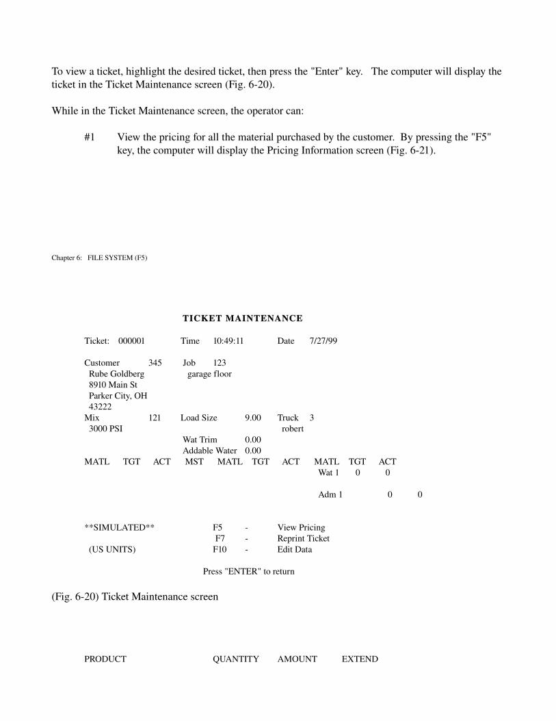
To view a ticket, highlight the desired ticket, then press the "Enter" key. The computer will display the ticket in the Ticket Maintenance screen (Fig. 620).
While in the Ticket Maintenance screen, the operator can:
#1 View the pricing for all the material purchased by the customer. By pressing the "F5" key, the computer will display the Pricing Information screen (Fig. 621).
Chapter 6: FILE SYSTEM (F5)
TICKET MAINTENANCE
Ticket: 000001 Time 10:49:11 Date 7/27/99
Customer 345 Job 123 Rube Goldberg garage floor 8910 Main St Parker City, OH 43222Mix 121 Load Size 9.00 Truck 3 3000 PSI robert
Wat Trim 0.00Addable Water 0.00
MATL TGT ACT MST MATL TGT ACT MATL TGT ACT Wat 1 0 0
Adm 1 0 0
**SIMULATED** F5 View PricingF7 Reprint Ticket
(US UNITS) F10 Edit Data
Press "ENTER" to return
(Fig. 620) Ticket Maintenance screen
PRODUCT QUANTITY AMOUNT EXTEND

3000 PSI 9.00 288.00 288.00Rebar 5.00 55.00 55.00
0.00 0.00 0.00 0.00 0.00 0.00 0.00 0.00 0.00 0.00 0.00 0.00 0.00 0.00 0.00
C.O.D. Delivery Sub Total 343.00Press “F10" to EDITPress ENTER to RETURN Sales Tax 6.000 20.58
Total Due 363.58
(Fig. 621) Pricing Information screen
Chapter 6: FILE SYSTEM (F5)
#2 Reprint the ticket. Press the "F7" key, the computer will display the Reprint Ticket screen (Fig. 622) in which it asks the operator if the ticket is to have the next current ticket number.
Do you wish to assignthe next ticket number (Y)es / (N)o / (C)ancel ?
(Fig. 622) Reprint Ticket screen
#3 Edit data. For the use of returned concrete, or correcting errors in the ship to address, etc... the operator can edit information by pressing the "F10" key.
Section 6.7.2: Delete Record
To delete a ticket from the list, highlight the desired ticket, then press the "Del" key. The computer will ask if the ticket is to be deleted. By pressing the "Y" key, the ticket will be deleted.
Section 6.7.3: Clear File
The "F3" key will delete specified tickets in the Ticket File. The computer will display the Clear Ticket

Warning screen (Fig. 623) before any tickets are deleted. Tickets can be deleted by number, date, or the complete ticket file.
Clear Ticket File
WARNING!! THIS ROUTINE PERMANENTLYERASES ALL DATA IN THE TICKET FILE
Clear Tickets by Number (Y/N) ? *OR*
Clear Tickets by Date (Y/N) ?*OR*
Clear All Tickets (Y/N) ?
(Fig. 623) Clear Ticket Warning screen
Chapter 6: FILE SYSTEM (F5)
Section 6.7.4: Go To Ticket
To help find a ticket, if the ticket number is known, press the "F6" key and then input the ticket number. If the ticket still exists in the file, the computer will display it.
Section 6.7.5: Go To Date
To view tickets batched on a certain day, press the "F7" key and enter the desired date. The computer will display the tickets for that day.
Section 6.7.6: Void Ticket
When batching in the Automatic Mode, the system automatically prints a ticket. If for some reason the ticket needs to be voided but kept on record, this can be done by pressing the "F10" key. If the control system is linked to another computer that requires ticket information, it will not send voided tickets out to be processed or billed.
Section 6.7.7: Export Tickets
By pressing the “F11" key, the complete ticket file will be exported to another computer (controller, billing or the main headquarters) for processing. The computer will ask if it is okay to export before the action is performed.
Section 6.8: Pricing Files

The Pricing Files is used to set the tax rate on material being sold. The computer will display the Pricing Files screen (Fig. 624).
PRICING FILES
SELECT 1. TAX RATES
(Fig. 624) Pricing Files screen
After choosing option #1, the computer will display the Tax Rate screen (Fig. 625) which allows the operator to set the tax rate percent.
Tax Rates
Standard Tax Rates 5.500%
(Fig. 625) Tax Rate screen
Chapter 7: REPORT MENU (F6)
CHAPTER 7: REPORT MENU (F6)
The ERIE control system is capable of displaying and printing information on Customers, Jobs, Mix Designs, Trucks and Products. Printed reports for Material Usage, Production, and Plant Setup can also be printed. Any one of these reports is a good source of information.
To access the Reports, press the "F6" key while in the Main Menu screen. This will display the Report submenu screen (Fig. 70), which contains the list of available reports that can beprinted.
REPORT MENU
SELECT
1. MIX DESIGN LIST2. JOB MASTER LISTS3. MIX DESIGN LISTS4. TRUCK LISTS5. PRODUCT LISTS6. USAGE REPORTS7. PRODUCTION REPORTS8. PLANT SETUP REPORT

(Fig. 70) Report submenu screen
Section 7.1: Customer Master List
The Customer Master List will print a report on customer information (Customer, ID, Name, Address). The computer will ask whether to print a detailed report or not ("Print Detail Y/N ?"). A nondetailed report will print a brief description of the customer.
NOTE:A detailed report can be long, check the printer for paper.
An example of a detailed Customer Report is displayed in Figure (71).
Chapter 7: REPORT MENU (F6)
____________________________________________________________________
CUSTOMER REPORT
CUSTOMER ID NAME ADDRESS
12 142 CONCRETE CONT. INC. 8945 W. 32 ND ST.ERIE, PA. 165128145551212
61 CB1 CENTELLI BROS 545 PEACH ST.ERIE, PA. 165028145552345
____________________________________________________________________
(Fig. 71) Example: Detailed Customer Report
Section 7.2: Job Master List
The Job Master List is a complete Job Summary. The computer will ask whether to print a detailed report or not ("Print Detail Y/N ?"). A nondetailed report will be a brief description of each Job.

NOTE: A detailed report can be long, check the printer for paper.
An example of a detailed Job Summary Report is displayed in Figure (72).
_____________________________________________________________________________________
JOB SUMMARY JUL 22, 1999 PAGE 1
CUSTOMER ID: 1 JOB ID: 1 DELIVERY: 04/ 9/99CUSTOMER NAME: Steven's Mats.ORDERED: 50.00 DELIVERED: 50.00 LOADS: 5BATCH SIZE: 10.00 MIX DESIGN: 352 DESCRIPTION: 3000 PSI
CUSTOMER ID: 625 JOB ID: 22 DELIVERY: 06/21/99CUSTOMER NAME: Ajax PavingORDERED: 10.00 DELIVERED: 10.00 LOADS: 1BATCH SIZE: 10.00 MIX DESIGN: SPECIAL DESCRIPTION: Foundation
_____________________________________________________________________________________
(Fig. 72) Example: Detailed Job Summary Report
Chapter 7: REPORT MENU (F6)
Section 7.3: Mix Design List
The Mix Design List prints a report of all the Mix Designs in the computer system. The computer will ask whether to print a detailed report or not ("Print Detail Y/N ?"). A nondetailed report will be a brief description of each Mix Design.
NOTE: A detailed report can be long, check the printer for paper.
An example of a Detailed Mix Design Report is displayed in Figure (73).
________________________________________________________________________________MIX DESIGN REPORT
MIX NUMBER: 1 U.S. UNITSDESCRIPTION: 3000 PSIAGG: 101200 111800 14400 00 00 00CMT: 20600 21220 00 WATER: 22.0 MAX WATER: 23.0ADM: A120.00oz A23.50oz 00oz 00oz 00oz 00oz
MIX NUMBER: 25 METRICDESCRIPTION: SPECIALAGG: 10850 111000 00 00 00 00

CMT: 20420 21150 00 WATER: 45.0 MAX WATER: 47.0ADM: A145.00ml A215ml 00ml 00ml 00ml 00ml
________________________________________________________________________________
(Fig. 73) Example: Detailed Mix Design Report
Section 7.4: Truck List
The Truck List prints a historical data collection report for each truck. The computer will ask whether to print a detailed report or not ("Print Detail Y/N").
An example of a Detailed Truck Report is displayed in Figure (74). ________________________________________________________________________________________ TRUCK REPORT
DISCHARGE DISCHARGE LOADS YARDSTRUCK ID DRIVER NAME RATE SEQUENCE DELIVERED DELIVERED
1 Barry Kirk 100% 2 30 250 2 Jan Igras 75% 1 12 120 3 John Euliano 120% 3 10 100 4 Terry Dunn 50% 3 42 450
________________________________________________________________________________________
(Fig. 74) Example: Detailed Truck Report
Chapter 7: REPORT MENU (F6)
Section 7.5: Product List
The Product List prints a report of other products being sold. The computer will ask whether to print a detailed report or not ("Print Detail Y/N ?"). This report also includes prices.
An example of a Detailed Product Report is displayed in Figure (75).
________________________________________________________________________________
PRODUCT REPORT
PRODUCT ID: 1 PRODUCT DESCRIPTION: ½" RebarUNIT PRICE: 0.65 UNIT OF MEASURE: Per ftTAXABLE: Y BEGINNING BALANCE: 124.5SHIPPED TO DATE: 25.5 RECEIVED TO DATE: 646BALANCE ON HAND: 745 LAST ACTIVITY: 06/12/99
PRODUCT ID: M12 PRODUCT DESCRIPTION: fiberUNIT PRICE: 1.25 UNIT OF MEASURE: Per lbTAXABLE: Y BEGINNING BALANCE: 50SHIPPED TO DATE: 11.0 RECEIVED TO DATE: 0BALANCE ON HAND: 39.5 LAST ACTIVITY: 12/05/98

________________________________________________________________________________
(Fig. 75) Example: Detailed Product Report
Chapter 7: REPORT MENU (F6)
Section 7.6: Usage Report
The Usage Report will automatically print a Detailed Material Usage Report. This report will display 2 usage tables reflecting 'usage since dates'. The Beginning Balance Date is set from the last rollover of inventory.
An example of a detailed Material Usage Report is displayed in Figure (76).
____________________________________________________________________________________________ MATERIAL USAGE REPORT DATE: 7/22/96
BEGINNING SINCE 7/19/96 SINCE 7/21/96MATERIAL BALANCE RECEIVED SHIPPED BALANCE ACTUAL TARGET ACTUAL TARGETNAME 07/19/96 TO DATE TO DATE ON HAND USAGE USAGE USAGE USAGE
SAND 3479651 965000 45780 4398871 45780 44152 8255 8100½" STONE 2186532 0 42100 4144432 42100 41936 7728 76003/8" STONE 1234750 58500 19100 1274150 19100 10476 1254 12003" STONE 0 0 0 0 0 0 0 0
0 0 0 0 0 0 0 0 0 0 0 0 0 0 0 0
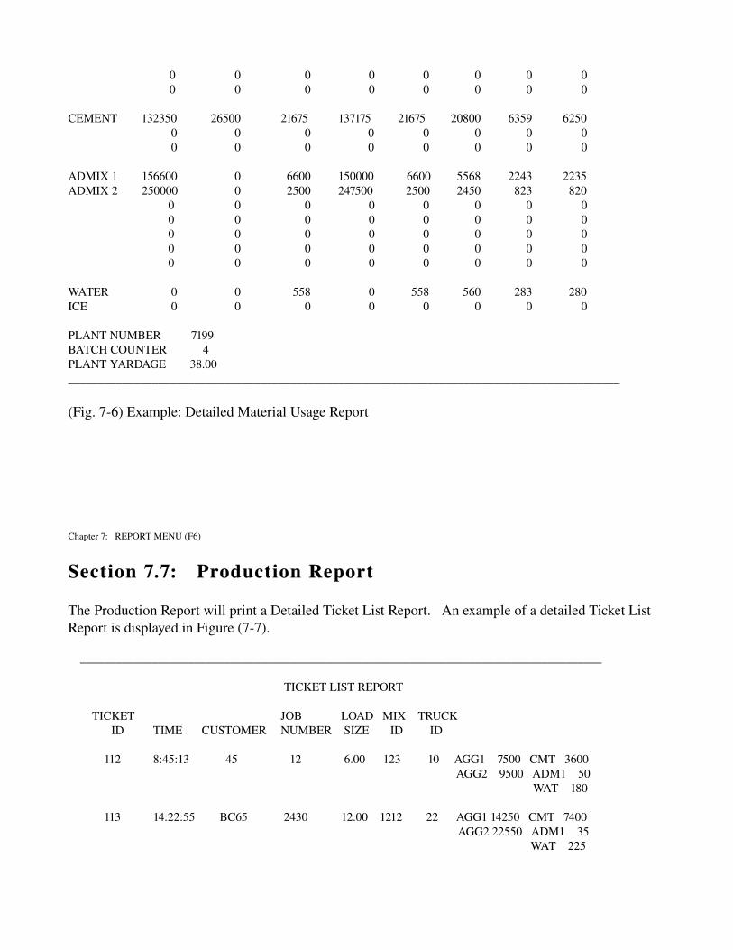
0 0 0 0 0 0 0 0 0 0 0 0 0 0 0 0
CEMENT 132350 26500 21675 137175 21675 20800 6359 6250 0 0 0 0 0 0 0 0 0 0 0 0 0 0 0 0
ADMIX 1 156600 0 6600 150000 6600 5568 2243 2235ADMIX 2 250000 0 2500 247500 2500 2450 823 820
0 0 0 0 0 0 0 0 0 0 0 0 0 0 0 0 0 0 0 0 0 0 0 0 0 0 0 0 0 0 0 0 0 0 0 0 0 0 0 0
WATER 0 0 558 0 558 560 283 280ICE 0 0 0 0 0 0 0 0
PLANT NUMBER 7199BATCH COUNTER 4PLANT YARDAGE 38.00____________________________________________________________________________________________
(Fig. 76) Example: Detailed Material Usage Report
Chapter 7: REPORT MENU (F6)
Section 7.7: Production Report
The Production Report will print a Detailed Ticket List Report. An example of a detailed Ticket List Report is displayed in Figure (77).
_______________________________________________________________________________________
TICKET LIST REPORT
TICKET JOB LOAD MIX TRUCKID TIME CUSTOMER NUMBER SIZE ID ID
112 8:45:13 45 12 6.00 123 10 AGG1 7500 CMT 3600
AGG2 9500 ADM1 50 WAT 180
113 14:22:55 BC65 2430 12.00 1212 22 AGG1 14250 CMT 7400
AGG2 22550 ADM1 35 WAT 225

_______________________________________________________________________________________
(Fig. 77) Example: Detailed Ticket List Report
Section 7.8: Plant Setup Report
The Plant Setup Report prints a detailed report on the settings for the plant controls. This report lists all the time settings for gate controls, total weights for materials, discharge sequence of materials and lists how the materials are numbered. This report can be faxed to Erie Strayer Co. for technical assistance at 8144523422. (Attn: Service Dept.)
Chapter 8 UTILITIES (F7)
CHAPTER 8: UTILITIES (F7)
The Utilities submenu screen (Fig. 80) can be accessed by pressing the "F7" key from the Main Menu screen.
UTILITIES
SELECT
1. PLANT SETUP 2. PLANT CONFIGURATION 3. DIAGNOSTICS 4. FILE MAINTENANCE

(Fig. 80) Utilities submenu screen
Because the options in the Utilities submenu screen are so important and very detailed, 3 of the 4 options will be discussed in the following Chapters. A brief description will be given in this Chapter for each option.
Section 8.1: Plant Setup
This option gives access to the plant parameters and settings. The Plant Setup submenu screen (Fig. 90) will be the first screen displayed. From the submenu screen, the plant can be adjusted to run at peak efficiency. (see Chapter 9, page 47)
Section 8.2: Plant Configuration
The Plant Configuration screen (Fig. 81) is just an information screen and no Chapter will follow. The screen will display the complete system configuration. This is the information that will be needed if program changes or updates are needed in the control system. The contract number is displayed for future reference and technical assistance.
Chapter 8 UTILITIES (F7)
Current System Configuration
SENTRY 7188 System Version 3.200Jan 25 2000 14:01:39
Control Mix Design
4 Aggregates in 4 Batchers 6 of 4 Aggregates 4 Cements in 1 Batcher 3 of 4 Cements 7 Admixtures 5 of 7 Admixture 1 Water by Meter 1 Water
Wet Mix Operation

Measurement type: U.S./Metric Units Language: English Threaded Control System
Press ENTER To Continue
(Fig. 81) Plant Configuration screen
Section 8.3: Diagnostics
This option is used to troubleshoot the control system. The Plant Test submenu screen (Fig. 100, page 91) will appear. This section will help tell whether a problem is in the control system or plant wiring. (see Chapter 10, page 91)
Section 8.4: File Maintenance
The File Maintenance option will display the File Maintenance submenu screen (Fig. 110, page 97). From this submenu screen, the program data and plant data can be saved to a disk. This option is also where program changes and updates are installed. (see Chapter 11, page 97)
Chapter 9 PLANT SETUP
CHAPTER 9: PLANT SETUP
Before batching with the computer control system, the plant settings must be input into the Plant Setup screens. To access the Plant Setup screens, press the "F7" key at the Main Menu screen, and then choose option #1 at the Utilities submenu screen, the Plant Setup submenu screen (Fig. 90) will be displayed.
The Plant Setup submenu screen displays all the various sections of the batch plant that can or must be adjusted or set. This submenu may vary from plant to plant based on the special features associated with the needs of the batching process.

From the various selections of this menu, the parameters that determine the accuracy and consistency of the system are made. This part of the manual is the most important because it instructs the operator how to setup the system for efficient batching.
PLANT SETUP
SELECT
1. AGGREGATE BATCHER 1 SETUP 2. CEMENT BATCHER CEMENT 3. ADMIX SETUP 4. AGGREGATE SETUP 5. CEMENT SETUP 6. WATER SETUP 7. MIXER 1 CONTROLS 8. PLANT PARAMETERS 9. PRINTER SETUP 10. DISCHARGE SEQUENCE 11. TANDEM GATES 12. SET MOISTURE PROBE LIMITS 13. ICE SETUP 14. CMS SETUP
(Fig. 90) Plant Setup screen
NOTE:The settings shown in this manual are intended as a reference in understanding the operation of this system. They should not be taken as the final settings that will achieve optimum performance of the system. In practice, a thorough understanding of the functions of these settings will allow the operator to make the proper adjustments.
Chapter 9 PLANT SETUP
Section 9.1: Aggregate Batcher Setup
All of the settings made here will determine the operation of the Aggregate Weigh Batcher. The Aggregate Batcher 1 Setup screen (Fig. 91) displays the required parameters.
Contained on the screen are settings for Scale Capacity, Tare Zero, Weighing Tolerances (Over, Under, Minimum), Scale Balance Time, Zero Balance Time, Allow Fast Feed Resume?, Use Inching Discharge?, Discharge Full Open Point, Vibrator Turn On Delay, Vibrator Maximum On Time, Discharge Initial Open Time, Open Time, and Close Time.
If this system is being used on a plant with individual batchers, each batcher will have its own setup

screen.
AGGREGATE BATCHER 1 SETUP
SCALE CAPACITY 50000 lbs TARE ZERO 0050 lbs (+/)
WEIGHING TOLERANCES OVER 01.00 pct
UNDER 01.00 pct MINIMUM 0025 lbs
SCALE BALANCE TIME 01.00 sec ZERO BALANCE TIME 01.00 sec ALLOW FAST FEED RESUME ? N USE INCHING DISCHARGE ? Y DISCHARGE FULL OPEN POINT 0500 lbs VIBRATOR TURN ON DELAY 0003 sec VIBRATOR MAXIMUM ON TIME 04 sec DISCHARGE INITIAL OPEN 00.80 sec 00.95 sec
HOLD TIME 01.25 sec 01.55 secOPEN TIME 00.30 sec 00.40 sec CLOSE TIME 00.35 sec 00.45 sec
(Fig. 91) Aggregate Batcher Setup screen
Section 9.1.1: Scale Capacity
Scale Capacity is set in pounds. It tells the computer the maximum amount of material that can be weighed into the batcher. The value of this setting is determined by the maximum setting on the corresponding Dial Head or by the Rating Plate located on the corresponding batcher. The control system will not allow for batching of any material that exceeds the scale capacity setting.
Chapter 9 PLANT SETUP
Section 9.1.2: Tare Zero
Tare Zero is set in pounds. It sets a value above and below zero which the computer will accept the batcher as being empty or at zero. This is normally set to one (1) scale graduation or 0.1% of the scale capacity.
EXAMPLE: An Agg scale has a capacity of 40,000 lbs (40000 * .001 = 40). Set the value of Tare Zero to 40. As long as the scale reading to the computer remains within +/ 40 pounds of zero, the computer will be satisfied that the aggregate can be weighed up, or that when discharging the aggregate

from the batcher, the batcher is empty.
Section 9.1.3: Weighing Tolerances
Weighing Tolerances (Over, Under, Minimum) are set in percent for Over/Under and pounds for Minimum. The settings of Over and Under represent the maximum and minimum weight in the batcher that the computer will accept as being within the target weight window during the weigh up.
EXAMPLE: The settings for Over and Under are set at 01.00. Therefore, a tolerance percentage of 1% is allowed for the Over and Under. If the target weight for the weigh up is 10,000 pounds, the computer will accept a window of 9,900 pounds to 10,100 pounds as being within the tolerances set.
NOTE: Local regulations may apply for the settings of these tolerances.
As a general rule though, these settings are normally set at 01.00.
The Minimum is set in pounds. It represents the lowest tolerance that the computer will accept for either an Over or Under condition. The value set for the Minimum is normally calculated by using .05% of the scale capacity. It will normally come into play when batching less than 1 yard of concrete.
EXAMPLE: The weigh batcher has a scale capacity of 40000 pounds, (40000 * .0005 = 20). Therefore a setting of 20 will be entered. ½ yard of aggregate is weighed with a target weight of 750 pounds. The Over and the Under are set at 01.00. The Minimum is set at 20 pounds. The window of acceptance around the target weight using the 1% setting gives a +/ 7.5 pounds or a window of 742.5 to 757.5 pounds. This would be a difficult tolerance to maintain in the weigh system of the batch plant. The 20 pound Minimum setting gives a window of acceptance around the target weight of 730 to 770 pounds which is within the capability of a batch plant weigh system to achieve.
Chapter 9 PLANT SETUP
Section 9.1.4: Scale Balance Time
Scale Balance Time is set in seconds. It allows the weigh batcher to settle out between the Fast Feed operation, the Jog operation, and between each successive Jogs, before the computer will take a reading of the scale weight. This setting is determined by the physical movement of the scale during weighup. Start with an arbitrary setting of 02.00 seconds. In general, it is desirable to have this time set as low as possible.
EXAMPLE: A setting of 02.00 seconds is entered for Scale Balance Time. Observations by the operator indicate the computer is reading the scale before the batcher has settled out. The setting of 02.00 should then be raised to 02.50 and retested to ensure that the setting is correct. If further adjustments are necessary, continue to raise the setting by intervals of 0.5.

EXAMPLE: A setting of 02.00 seconds is entered for Scale Balance Time. Observations by the operator indicate the computer is reading the scale too long after the batcher has settled out. The setting of 02.00 should be lowered to 01.50 and retested to ensure that the setting is correct. If further adjustments are necessary, continue to lower the setting by intervals of 0.5.
Section 9.1.5: Zero Balance Time
Zero Balance Time is set in seconds. It tells the computer to wait a certain period of time after sensing Tare Zero before closing the gate(s) and taking a final reading of the scale. This setting is used to ensure that the batcher scale is at or below Tare Zero after the Discharge Cycle is complete. Start with an arbitrary setting of 01.00 seconds. In general, it is desirable to have this time set as low as possible.
EXAMPLE: A setting of 01.00 seconds is entered for Zero Balance Time. Observations by the operator indicate the batcher scale is above Tare Zero after the Discharge Cycle is complete. The setting of 01.00 should then be raised to 01.50 and then retested to ensure the new setting is correct.
Section 9.1.6: Allow Fast Feed Resume
As Aggregate, Cement, or Water are weighed, the material reaches a point defined as "Preliminary Cutoff". At preliminary cutoff the computer reads the scale (batcher) weight, as displayed by the load cell indicator, and determines if the weight is within the Over Tolerance, Under Tolerance, or Minimum Tolerance settings as defined in the Plant Setup for the Aggregate, Cement, or Water scales. If the weight is within tolerance, the computer is satisfied and displays a "C" for complete or commences weigh up of another material if called for. If the weight is below the Under Tolerance, the computer will jog the gate or valve open at intervals as defined in Plant Setup until the weigh up is complete and within defined tolerances.
Chapter 9 PLANT SETUP
Sometimes the inertia of a material as it drops into an empty scale (batcher) may be enough to cause the scale weight reading to prematurely exceed the preliminary cutoff weight set in the aggregate, cement, or water setup. When the material settles, the weight reading can be far below cutoff and the control system must jog the remainder of the material into the scale until the tolerance is achieved. This can sometimes be several hundred pounds. The resultant increased number of jogs is time consuming, wastes air and causes increased wear and tear on the gates or valves.
To overcome this problem, the Aggregate, Cement, and Water batcher setup pages have an option called "Fast Feed Resume". If "N" (No) is selected , the computer will simply jog the material until the tolerance for that material is satisfied, regardless of how many jog cycles are required. If "Y" (Yes) is selected, and if the scale weight is below the preliminary cutoff, the computer will resume the fast feed cycle rather than jog the material until the tolerance for that material is satisfied. This eliminates unnecessary jogging of the gates or valves.

Section 9.1.7: Use Inching Discharge
Use Inching Discharge? is a Y/N response. The system offers two methods of discharging aggregate from the batcher. A "N" response tells the computer to open the batcher discharge gate(s) wide during the entire Discharge Cycle. A "Y" response tells the computer to control the rate of discharge from the batcher on a pounds per second basis. In general, a "Y" response is used when the discharge gate is controlled by a double action solenoid valve. An "N" response is used when the discharge gate is controlled by a single action solenoid valve or a high capacity Batch Transfer Conveyor.
Section 9.1.8: Discharge Full Open Point
Discharge Full Open Point is set in pounds. It gives the computer a point in the Discharge Cycle to open the gate(s) wide and turn on the vibrator in order to get the last of the aggregate out of the scale. As a general rule it is set to the Aggregate Discharge Rate which is set in the Discharge Sequence. If this setting causes either the belt to flood or the aggregate to overflow the charging chute, then the setting should be set to a lower value.
EXAMPLE: The Discharge Full Open Point is set at 250 pounds. While the aggregate is being discharged, the computer senses when there is 250 pounds left in the batcher. The computer opens the gate(s) wide and turns on the vibrator. The gate(s) remain wide open and the vibrator remains on until the weight in the batcher returns to Tare Zero and the computer times out the Zero Balance Time. The computer then closes the gate(s) and turns off the vibrator.
Chapter 9 PLANT SETUP
Section 9.1.9: Vibrator Turn on Delay
Vibrator Turn On Delay is set in seconds. This setting tells the computer how long to wait before turning on the vibrator if the Aggregate Discharge Rate from the batcher falls below the minimum discharge rate as determined by the settings in the Discharge Sequence. There is no predetermined correct setting for this value. In general, it depends upon how freely the aggregates being used flow. The "stickier" the aggregate, the harder it is to flow and the lower this setting will be. In most cases this value will be set from 1 to 5 seconds. In cases where the sand tends to hang up constantly, this setting can be set to 0 seconds.
EXAMPLE: Vibrator Turn On Delay is set to 3 seconds. In the Discharge Sequence, the setting for Aggregate Discharge is 200 lbs with a +/ of 15%. The computer looks for a Discharge Rate between 170 to 230 lbs/sec. The computer reads the weight of aggregate in the scale and calculates the rate of discharge. It senses the Discharge Rate has dropped to 100 lbs/sec. The computer waits 3 seconds and then turns the vibrator on if the rate has not increased to the minimum required.

Section 9.1.10: Vibrator Maximum on Time
Vibrator Maximum On Time is set in seconds. It works in conjunction with the Vibrator Turn On Delay and represents the length of time the vibrator will stay on. In general this setting will be 1 to 3 seconds. You want the vibrator to stay on only long enough to start the aggregate flowing again.
EXAMPLE: The Vibrator Maximum On Time is set to 02 seconds. The Vibrator Turn On Delay is set to 03 seconds. The Discharge Rate falls below the minimum. After 3 seconds, the vibrator comes on for 2 seconds. This pattern: 3 seconds off 2 seconds on continues until the Discharge Rate rises to the minimum allowable parameter.
Section 9.1.11: Discharge Initial Open
NOTE:On systems with an cumulative weigh batcher, there will be multiple columns for Discharge Initial Open, Open Time, and Close Time, which allows control for each gate of the weigh batcher.
NOTE: The setting of Discharge Initial Open, Open Time and Close Time work together to control the rate of discharge from the batcher. The setting for Open Time and Close Time are referred to as the Inching Controls. Before any of these settings are made, it is important that the speed of action of the batcher gate (s) be correctly adjusted so that optimum control from the computer can be achieved. Set the air pressure regulator to the solenoid valves to 120 PSIG. Locate the double acting solenoid air valve corresponding
Chapter 9 PLANT SETUP
to the batcher gate that needs adjusted. It will be located on a manifold assembly with other solenoid air valves near the batcher. There are two solenoid coils, each with a manual override adjustment used to open and close the batcher gate. On each side, sandwiched between the solenoid and the manifold base of the air valve is an adjustment screw used to control the speed of action of the gate. Clockwise adjustment slows down the speed of action and counterclockwise adjustment increases the speed of action. Adjustments should be made on an empty batcher. Set the speed of opening to approximately 1.5 2.0 seconds and the speed of closing to approximately 1.5 2.0 seconds. Repeated opening and closing of the batcher gate using the manual override buttons will be necessary to achieve this setting.
Discharge Initial Open is set in seconds. It determines how far the batcher gate(s) will open at the start of the Discharge Cycle. The setting of this value depends upon the ability of the aggregates to flow through the gate(s). In general, a setting of 0.50 seconds is a good initial setting to start with. Further adjustments will be required based upon observations by the operator.
EXAMPLE: 0.50 seconds is entered in the Discharge Initial Open. When the batcher gate(s) first open, no aggregate is discharged from the batcher. Therefore, the setting of 0.50 seconds is too low and must be raised. As a rule, make adjustments by 0.05 second intervals and then retest. Several

adjustments may be necessary.EXAMPLE: 0.50 seconds is entered in the Discharge Initial Open. When the batcher gate(s)
first open, too much aggregate is discharged from the batcher. Therefore, the setting of 0.50 seconds is too high and must be lowered. As in the previous example, make adjustments by 0.05 second intervals.
Section 9.1.12: Hold Time
The Hold Time gives the computer control system a set value to give the material in the scale time to settle before the computer reacts by opening or closing the scale gates to maintain the discharge rate (Chpt 9, page 83) out of the scale. 1.5 seconds is a good number to start out with.
Section 9.1.13: Open Time
Open Time is set in seconds. It determines how far the batcher gate(s) will open when adjustments to the Discharge Rate are made by the computer. The setting should cause movement not greater than 1 to 2 inches with each Open pulse sent by the computer. In general, start with a setting of 0.10 seconds.
Section 9.1.14: Close Time
Close Time is set in seconds. It determines how far the batcher gate(s) will close when adjustments to the Discharge Rate are made by the computer. As in the case with the Open Time setting, movement not greater than 1 to 2 inches should occur with each Close pulse sent by the computer. Start with a setting of 0.10 seconds.
Chapter 9 PLANT SETUP
Section 9.1.15: How Inching Controls Work
How Inching Controls Work: The Open Time and Close Time settings are referred to as the Inching Controls. They derive this name by the fact that when properly set they will cause the gate(s) to open or close a distance not greater than 1 to 2 inches with each Open or Close adjustment from the computer. For this reason, it is very important that these settings are correctly made. Too high a setting will result in movement of the gate(s) greater than the desired 1 to 2 inches. This will result in over compensation of the discharge rate and cause erratic discharge of the aggregate(s). Too low a setting will result in movement of the gate(s) less than the desired 1 to 2 inches. This will result in under compensation of the discharge rate and cause excessive adjustments to the flow rate.
Normal settings of approximately 0.05 to 0.10 seconds will achieve the desired results. Visual observation of the action of the gate(s) will be required to determine the exact setting.
EXAMPLE: 0.15 seconds are entered in Open Time and Close Time. Observation of the gate(s) reveals that the open adjustments cause movement of 3 inches and the close adjustments cause movement of 1 inch. The Open Time setting is too high and the Close Time setting is correct. Reduce the setting of the Open Time to 0.10 seconds and retest using visual observations to determine whether the 1 inch movement has been achieved.

EXAMPLE: 0.10 seconds are entered in Open Time and Close Time. Observation of the gate(s) reveals that the open adjustments cause movement of 1 inch and close adjustments cause movement of 1/4 inch . The Open Time setting is correct and the Close Time setting is too low. Increase the Close Time setting to 0.15 seconds and retest using visual observations to determine whether the 1 inch movement has been achieved.
Section 9.2: Cement Batcher Setup
Cement Batcher Setup allows the operator to adjust the timing of the cement batcher gates and capacities.
The Cement Batcher Setup screen (Fig. 92) displays the settings for Scale Capacity, Tare Zero, Weighing Tolerances (Over, Under, Minimum), Scale Balance Time, Zero Balance Time, Allow Fast Feed Resume?, Use Inching Discharge?, Discharge Full Open Point, Vibrator Turn On Delay, Vibrator Maximum On Time, Discharge Initial Open Time, Open Time, and Close Time.
All of the settings made here will determine the operation of the Weigh Batcher. If this system is being used on a plant with individual batchers, then each batcher will have its own setup screen.
Chapter 9 PLANT SETUP
CEMENT BATCHER SETUP 1
SCALE CAPACITY 10000 lbs TARE ZERO 0010 lbs (+/)
WEIGHING TOLERANCES OVER 01.00 pct
UNDER 01.00 pct MINIMUM 0020 lbs
SCALE BALANCE TIME 01.00 sec ZERO BALANCE TIME 01.00 sec ALLOW FAST FEED RESUME ? N USE INCHING DISCHARGE ? Y DISCHARGE FULL OPEN POINT 0150 lbs VIBRATOR TURN ON DELAY 0003 sec VIBRATOR MAXIMUM ON TIME 04 sec DISCHARGE INITIAL OPEN 00.50 sec
HOLD TIME 00.75 secOPEN TIME 00.20 sec CLOSE TIME 00.15 sec
(Fig. 92) Cement Batcher Setup screen

Section 9.2.1: Scale Capacity
Scale Capacity is set in pounds. It tells the computer the maximum amount of material that can be weighed into the batcher. The value of this setting is determined by the maximum setting on the corresponding Dial Head or by the Rating Plate located on the corresponding batcher. The control system will not allow for batching of any material weight that exceeds the scale capacity setting.
Section 9.2.2: Tare Zero
Tare Zero is set in pounds. It sets a value above and below zero which the computer will accept the batcher as being empty or at zero. This is normally set to one (1) scale graduation or 0.1% of the scale capacity.
EXAMPLE: A cement scale has a capacity of 10,000 lbs (10000 * .001 = 10). Set the value of Tare Zero to 10. As long as the scale reading to the computer remains within +/ 10 pounds of zero, the computer will be satisfied that the cement can be weighed up, or that when discharging the cement from the batcher, the batcher is empty.
Chapter 9 PLANT SETUP
Section 9.2.3: Weighing Tolerances
Weighing Tolerances (Over, Under, Minimum) are set in percent for Over/Under and pounds for Minimum. The settings of Over and Under represent the maximum and minimum weight in the batcher that the computer will accept as being within the target weight window during the weigh up.
EXAMPLE: The settings for Over and Under are set at 01.00. Therefore, a tolerance percentage of 1% is allowed for the Over and Under. If the target weight for the weigh up is 5,000 pounds, the computer will accept a window of 4,950 pounds to 5,050 pounds as being within the tolerances set.
NOTE: Local regulations may apply for the settings of these tolerances.
As a general rule though, these settings are normally set at 01.00.
The Minimum is set in pounds. It represents the lowest tolerance that the computer will accept for either an Over or Under condition. The value set for the Minimum is normally calculated by using .05% of the scale capacity. It will normally come into play when batching less than 1 yard of concrete.
EXAMPLE: The weigh batcher has a scale capacity of 10000 pounds, (10000 * .0005 = 5). Therefore a setting of 5 will be entered. ½ yard of cement is weighed with a target weight of 250

pounds. The Over and the Under are set at 01.00. The Minimum is set at 5 pounds. The window of acceptance around the target weight using the 1% setting gives a +/ 2.5 pounds or a window of 247.5 to 252.5 pounds. This would be a difficult tolerance to maintain in the weigh system of the batch plant. The 5 pound Minimum setting gives a window of acceptance around the target weight of 245 to 255 pounds which is within the capability of the batch plant weigh system to achieve.
Section 9.2.4: Scale Balance Time
Scale Balance Time is set in seconds. It allows the weigh batcher to settle out between the Fast Feed operation, the Jog operation, and between each successive Jog, and then the computer will take a reading of the scale weight. This setting is determined by the physical movement of the scale during weighup. Start with an arbitrary setting of 02.00 seconds. In general, it is desirable to have this time set as low as possible.
EXAMPLE: A setting of 02.00 seconds is entered for Scale Balance Time. Observations by the operator indicate the computer is reading the scale before the batcher has settled out. The setting of 02.00 should then be raised to 02.50 and retested to ensure that the setting is correct. If further adjustments are necessary, continue to raise the setting by intervals of 0.5.
Chapter 9 PLANT SETUP
EXAMPLE: A setting of 02.00 seconds is entered for Scale Balance Time. Observations by the operator indicate the computer is reading the scale too long after the batcher has settled out. The setting of 02.00 should be lowered to 01.50 and retested to ensure that the setting is correct. If further adjustments are necessary, continue to lower the setting by intervals of 0.5.
Section 9.2.5: Zero Balance Time
Zero Balance Time is set in seconds. It tells the computer to wait a certain period of time after sensing Tare Zero before closing the cement valve(s) and taking a final reading of the scale. This setting is used to ensure that the batcher scale is at or below Tare Zero after the Discharge Cycle is complete. Start with an arbitrary setting of 01.00 second. In general, it is desirable to have this time set as low as possible.
EXAMPLE: A setting of 01.00 second is entered for Zero Balance Time. Observations by the operator indicate the batcher scale is above Tare Zero after the Discharge Cycle is complete. The setting of 01.00 should then be raised to 01.50 and then retested to ensure the new setting is correct.
Section 9.2.6: Allow Fast Feed Resume
As Aggregate, Cement, or Water are weighed, the material reaches a point defined as "Preliminary Cutoff". At preliminary cutoff the computer reads the scale (batcher) weight, as displayed by the load cell indicator, and determines if the weight is within the Over Tolerance, Under Tolerance, or Minimum Tolerance settings as defined in the Plant Setup for the Aggregate, Cement, or Water scales. If the weight is within tolerance, the computer is satisfied and displays a "C" for complete or commences

weigh up of another material if called for. If the weight is below the Under Tolerance, the computer will jog the gate or valve open at intervals as defined in Plant Setup until the weigh up is complete and within defined tolerances.
Sometimes the inertia of a material as it drops into an empty scale (batcher) may be enough to cause the scale weight reading to prematurely exceed the preliminary cutoff weight set in the aggregate, cement, or water setup. When the material settles, the weight reading can be far below cutoff and the control system must jog the remainder of the material into the scale until the tolerance is achieved. This can sometimes be several hundred pounds. The resultant increased number of jogs is time consuming, wastes air and causes increased wear and tear on the gates or valves.
To overcome this problem, the Aggregate, Cement, and Water batcher setup pages have an option called "Fast Feed Resume". If "N" (No) is selected , the computer will simply jog the material until the tolerance for that material is satisfied, regardless of how many jog cycles are required. If "Y" (Yes) is selected, and if the scale weight is below the preliminary cutoff, the computer will resume the fast feed cycle rather than jog the material until the tolerance for that material is satisfied. This eliminates unnecessary jogging of the gates or valves.
Chapter 9 PLANT SETUP
Section 9.2.7: Use Inching Discharge
Use Inching Discharge? is a Y/N response. The system offers two methods of discharging cement from the batcher. An "N" response tells the computer to open the batcher discharge valve(s) wide during the Discharge Cycle until the scale comes to tare zero. A "Y" response tells the computer to control the rate of discharge from the batcher on a pounds per second basis. In general, a "Y" response is used when the discharge valve is controlled by a double action solenoid valve. An "N" response is used when the discharge valve is controlled by a single action solenoid valve.
Section 9.2.8: Discharge Full Open Point
Discharge Full Open Point is set in pounds. It gives the computer a point in the Discharge Cycle when it should open the valve wide and turn on the vibrator in order to get the last of the cement out of the scale. As a general rule it is set to the cement discharge rate calculated in the Discharge Sequence. If this setting causes the cement to overfill the truck charging chute/cement discharge tube, then the setting should be set to a lower value.
EXAMPLE: The Discharge Full Open Point is set at 100 pounds. While the cement is being discharged, the computer senses there is 100 pounds left in the batcher. The computer opens the valve wide and turns on the vibrator. The valve remains wide open and the vibrator remains on until the weight in the batcher returns to Tare Zero and the computer times out the Zero Balance Time. The computer then closes the valve and turns off the vibrator.
Section 9.2.9: Vibrator Turn on Delay
Vibrator Turn On Delay is set in seconds. It tells the computer how long to wait before turning on the

vibrator if the cement Discharge Rate from the batcher falls below the minimum level as calculated by the settings in the Discharge Sequence. There is no predetermined correct setting for this value. In general, it depends upon how freely the cement being used flows. The "thicker" the cement, the harder it is to flow and the lower this setting will be. In most cases this value will be set from 1 to 5 seconds. In cases where the cement tends to hang up constantly, this setting can be set to 0 seconds.
EXAMPLE: Vibrator Turn On Delay is set to 3 seconds. The computer calculates the Cement Discharge Rate at 50 lbs/sec with a +/ of 10%. The computer looks for a Discharge Rate between 45 to 55 lbs/sec. The computer reads the weight of the cement in the scale and calculates the rate of discharge. It senses the Discharge Rate has dropped to 20 lbs/sec. The computer waits 3 seconds and then turns the vibrator on if the rate has not increased to the minimum required.
Chapter 9 PLANT SETUP
Section 9.2.10: Vibrator Maximum on Time
Vibrator Maximum On Time is set in seconds. It works in conjunction with the Vibrator Turn On Delay and represents the length of time the vibrator will stay on. In general this setting will be 1 to 3 seconds. You want the vibrator to stay on only long enough to start the cement flowing again.
EXAMPLE: The Vibrator Maximum On Time is set to 02 seconds. The Vibrator Turn On Delay is set to 03 seconds. The Discharge Rate falls below the minimum. After 3 seconds, the vibrator comes on for 2 seconds. This pattern: 3 seconds off 2 seconds on continues until the Discharge Rate rises to the minimum allowable parameter.
Section 9.2.11: Discharge Initial Open
NOTE: The settings of Discharge Initial Open, Open Time and Close Time work together to control the rate of discharge from the batcher. The settings for Open Time and Close Time are referred to as the Inching Controls. Before any of these settings are made, it is important that the speed of action of the batcher valve be correctly adjusted so that optimum control from the computer can be achieved. Set the air pressure regulator to the solenoid valves to 80 PSIG. Locate the double acting solenoid air valve corresponding to the batcher valve that needs adjustment. It will be located on a manifold assembly with other solenoid air valves near the batcher. There are two solenoid coils, each with a manual slotted override button used to open and close the batcher valve. On each side, sandwiched between the solenoid and the manifold base of the air valve is an adjustment screw used to control the speed of action of the valve. Clockwise adjustment slows down the speed of action and counterclockwise adjustment increases the speed of action. Adjustments should be made on an empty batcher. Set the speed of opening to approximately 1.5 2.0 seconds and the speed of closing to approximately 1.5 2.0 seconds. Repeated opening and closing of the batcher gate using the manual override buttons will be necessary to achieve this setting.
Discharge Initial Open is set in seconds. It determines how far the batcher valve will open at the start of

the Discharge Cycle. The setting of this value depends upon the ability of the cement to flow through the valve. In general, a setting of 0.50 seconds is a good initial setting to start with. Further adjustments will be required based upon observations by the operator.
EXAMPLE 1: 0.50 seconds is entered in the Discharge Initial Open. When the batcher valve first opens, no cement is discharged from the batcher. Therefore, the setting of 0.50 seconds is too low and must be raised. As a rule, make adjustments by 0.05 second intervals and then retest. Several adjustments may be necessary.
EXAMPLE 2: 0.50 seconds is entered in the Discharge Initial Open. When the batcher valve first opens, too much cement is discharged from the batcher. Therefore, the setting of 0.50 seconds is too high and must be lowered. As in the previous example, make adjustments by 0.05 second intervals.
Chapter 9 PLANT SETUP
Section 9.2.12: Hold Time
The Hold Time gives the computer control system a set value to give the material in the scale time to settle before the computer reacts by opening or closing the scale gates to maintain the discharge rate (Chpt 9, page 83) out of the scale. 1.5 seconds is a good number to start out with.
Section 9.2.13: Open Time
Open Time is set in seconds. It determines how far the batcher valve will open when adjustments to the Discharge Rate are made by the computer. The setting should cause movement not greater than 1 to 2 inches with each Open pulse sent by the computer. In general, start with a setting of 0.10 seconds.
Section 9.2.14: Close Time
Close Time is set in seconds. It determines how far the batcher valve will close when adjustments to the Discharge Rate are made by the computer. As in the case with the Open Time setting, movement not greater than 1 to 2 inches should occur with each Close pulse sent by the computer. Start with a setting of 0.10 seconds.
Section 9.2.15: How Inching Controls Work
How Inching Controls Work: The Open Time and Close Time settings are referred to as the Inching Controls. They derive this name by the fact that when properly set they will cause the valve to open or close a distance not greater than 1 to 2 inches with each Open or Close adjustment from the computer. For this reason, it is very important that these settings are correctly made. Too high a setting will result in movement of the valve greater than the desired 1 to 2 inches. This will result in over compensation of the discharge rate and cause erratic discharge of the cement. Too low a setting will result in movement of the valve less than the desired 1 to 2 inches. This will result in under compensation of the discharge rate and cause excessive adjustments to the flow rate. Normally settings of approximately 0.05 to 0.10 seconds will achieve the desired results. Visual observation of the action of the valve will be required to determine the exact setting.

EXAMPLE 1: 0.15 seconds are entered in Open Time and Close Time. Observation of the valve reveals that the open adjustments cause movement of 3 inches and the close adjustments cause movement of 1 inch. The Open Time setting is too high and the Close Time setting is correct. Reduce the setting of the Open Time to 0.10 seconds and retest using visual observations to determine whether the 1 inch movement has been achieved.
EXAMPLE 2: 0.10 seconds are entered in Open Time and Close Time. Observation of the valve reveals that the open adjustments cause movement of 1 inch and close adjustments cause movement of 1/4 inch . The Open Time setting is correct and the Close Time setting is too low. Increase the Close Time setting to 0.15 seconds and retest using visual observations to determine whether the 1 inch movement has been achieved.
Chapter 9 PLANT SETUP
Section 9.3: Admix Setup
All the settings here will setup the admix system for operating in the control system. The Admix Setup screen (Fig. 93) will display the entries for Name, Bottle, Bottle Capacity, Dosage By Yard, Oz Per Count, Oz Per 1%, Over Tol, Under Tol and Bottle Empty.
ADMIX SETUP
NAME BOTTLE BOTTLE DOSAGE OZ PER OZ PER OVER UNDER BOTTLE (Y/N) CAPACITY BY YARD COUNT 1% TOL TOL EMPTY
AD1 Microair Y 04500 Y 002 000 01 01 00 AD2 Calcium Y 05000 Y 000 003 01 01 00 AD3 Reducer Y 02500 Y 001 000 01 01 00 AD4 Y 00000 Y 001 000 01 00 00 AD5 Y 00000 Y 001 000 01 00 00 AD6 Y 00000 Y 001 000 01 00 00 AD7 Y 00000 Y 001 000 01 00 00
(Fig. 93) Admix Setup screen
Section 9.3.1: Name
It is used to identify the admixture being used. The Name is ID'd to each admix in the Material Usage screen (Fig. 615, page 31). This name will appear on the Batch Cycle screen during WeighUp and Discharge and will be printed on the ticket if that option is included with the system.
Section 9.3.2: Bottle
Bottle is a Y/N response. It designates whether the admix is metered into a bottle or directly into the mix. If "Y" is entered, the admix is metered into a bottle during the Weighing Cycle. If "N" is entered,

the admix is metered directly into the mix during the Discharge Cycle. It is important the correct response be entered to reflect configuration of the admix system. An incorrect setting could adversely affect the operation of the system.
EXAMPLE: "N" is entered for Admix 1. With the configuration of the admix system, a bottle is used with Admix 1. The admixture should be metered into the bottle at the start of the Weighing Cycle. Because "N" is entered, the computer waits until the start of the Discharge Cycle to feed the admixture. The admixture feeds into the bottle and the computer is satisfied that the requirements of the system have been met. The result is the admixture not being put into the Mix.
Chapter 9 PLANT SETUP
Section 9.3.3 Bottle Capacity
Bottle Capacity is a 5 digit input set in ounces. This number should reflect the actual capacity of the admix bottles being used. Check the Rated Capacity of the bottle or consult with the Admix Representative. It is important that the correct bottle capacity be entered. The computer relies on this number to inform the operator if he attempts to batch more admix than the bottle can hold.
Section 9.3.4: Dosage By Yard
Dosage By Yard is a Y/N response. An "N" tells the computer to use the setting of Oz Per 1% (per weight of cement) to determine the Admix Dosage. A "Y" tells the computer to calculate the Admix dosage on a per yard of concrete basis.
Section 9.3.5: Oz Per Count
Oz Per Count is a 3 digit input. It tells the computer how many ounces passed through the meter with each electrical pulse the meter sent to the computer. This number can be found on the Rating Plate located on the meter or by checking with the Admix Representative. It is important that the correct number be entered. An incorrect setting will cause either to much or too little admix to be metered into the batch.
EXAMPLE: Oz Per Count is set at 1. The meter used gives 3 ounces per count. The Mix Design used calls for 5 ounces per yard. A 6 yard load is batched. The computer calculates 30 ounces for the 6 yard load. With Oz Per Count at 1, the computer calculates 30 pulses from the meter are required to feed 30 ounces. However, with the meter feeding 3 ounces every pulse, 30 pulses would be 90 ounces of admix.
Section 9.3.6: Oz Per 1%
Oz Per 1% is a 3 digit input. This setting is used to calculate admix dosage on a per hundred weight of cement basis. A setting of 1 would be used when calculating by ounces per hundred weight; 32 would be used when calculating quarts per hundred weight and so on for any amount per hundred weight desired.

Section 9.3.7: Over Tol
Over Tol is a 2 digit input based on counts. It designates how many pulses from the meter the computer will accept over the target amount. It is important to remember that this represents how many pulses, not ounces, the computer will accept over the target amount.
Section 9.3.8: Under Tol
Under Tol is a 2 digit input based on counts. It designates how many pulses from the meter the computer will accept under the target amount. It is used to compensate for the flow of admix past the valve when it is closing to prevent an over feed of the admix.
Chapter 9 PLANT SETUP
Section 9.3.9: Bottle Empty
Bottle Empty is set in seconds. It tells the computer to wait a set period of time after it senses the Bottle Empty indication before turning off the discharge signal to the admix system. This is normally used when you want to purge the admix line after each discharge.
NOTE: In many admix systems supplied today a time delay is adjustable in the controls supplied with that system. The use of this setting is only applicable where the ERIE Strayer system is used to directly control the admix system and not where the control signals are being used by an Admix Systems controls.
Section 9.4: Aggregate Setup
This is the setup screen for the overhead aggregate bin, which includes material ID's, moisture percent, and gate times.
The Aggregate Setup screen (Fig. 94) is used to make the adjustments or settings that allow the computer to control the feed of aggregates during the Weighing Cycle. Contained on this screen are settings for ID, Name, Moisture Pct, Jog Open, Small Batch Jog, Maximum Cutoff and Minimum Cutoff.
AGGREGATE SETUP
ID NAME MOISTURE JOG SMALL MAXIMUM MINIMUM PCT OPEN BATCH CUTOFF CUTOFF
JOG AGG 1 11 sand 04.50 0.40 0.80 0900 1500 AGG 2 12 3/4 stone 00.00 0.20 0.40 0950 0400 AGG 3 13 pea grvl 00.00 0.35 0.70 0700 0450 AGG 4 14 00 00.00 0.00 0.00 0000 0000
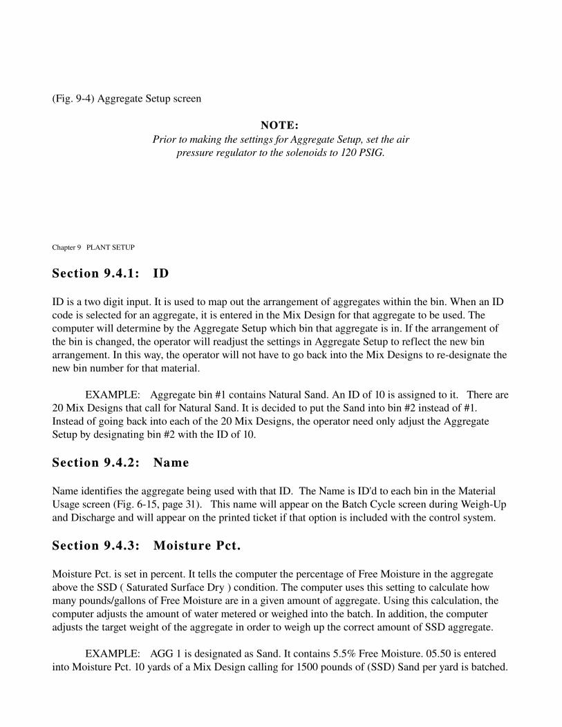
(Fig. 94) Aggregate Setup screen
NOTE: Prior to making the settings for Aggregate Setup, set the air
pressure regulator to the solenoids to 120 PSIG.
Chapter 9 PLANT SETUP
Section 9.4.1: ID
ID is a two digit input. It is used to map out the arrangement of aggregates within the bin. When an ID code is selected for an aggregate, it is entered in the Mix Design for that aggregate to be used. The computer will determine by the Aggregate Setup which bin that aggregate is in. If the arrangement of the bin is changed, the operator will readjust the settings in Aggregate Setup to reflect the new bin arrangement. In this way, the operator will not have to go back into the Mix Designs to redesignate the new bin number for that material.
EXAMPLE: Aggregate bin #1 contains Natural Sand. An ID of 10 is assigned to it. There are 20 Mix Designs that call for Natural Sand. It is decided to put the Sand into bin #2 instead of #1. Instead of going back into each of the 20 Mix Designs, the operator need only adjust the Aggregate Setup by designating bin #2 with the ID of 10.
Section 9.4.2: Name
Name identifies the aggregate being used with that ID. The Name is ID'd to each bin in the Material Usage screen (Fig. 615, page 31). This name will appear on the Batch Cycle screen during WeighUp and Discharge and will appear on the printed ticket if that option is included with the control system.
Section 9.4.3: Moisture Pct.
Moisture Pct. is set in percent. It tells the computer the percentage of Free Moisture in the aggregate above the SSD ( Saturated Surface Dry ) condition. The computer uses this setting to calculate how many pounds/gallons of Free Moisture are in a given amount of aggregate. Using this calculation, the computer adjusts the amount of water metered or weighed into the batch. In addition, the computer adjusts the target weight of the aggregate in order to weigh up the correct amount of SSD aggregate.
EXAMPLE: AGG 1 is designated as Sand. It contains 5.5% Free Moisture. 05.50 is entered into Moisture Pct. 10 yards of a Mix Design calling for 1500 pounds of (SSD) Sand per yard is batched.

The computer multiplies 1500 by 10 to arrive at a preliminary figure of 15,000 pounds. Since there is 5.5% Free Moisture in the Sand, the computer calculates how much of the 15,000 pounds is water. Converting 5.5% to its decimal equivalent will give .055. The 15,000 pounds is multiplied by .055 to arrive at a figure of 825 pounds of Free Moisture. This is converted to gallons by dividing it by 8.33 (the weight of 1 gallon of water) to arrive at 99 gallons. The computer subtracts 99 gallons from the total amount of water called for in the batch to determine how many gallons should be added by the batch plant. The computer also adjusts the target weight by 825 pounds for a new target weight of 15,825 pounds.
Chapter 9 PLANT SETUP
Section 9.4.4: Jog Open
Jog Open is set in seconds. It determines the amount of aggregate that drops with each Jog of the feed gate(s). Jogs occur during the Weighing Cycle immediately following the Fast Feed. The aggregate being batched is weighed up to a preliminary cutoff "X" number of lbs under the target. The computer closes the feed gate(s) and waits the Scale Balance Delay. The computer then Jogs the feed gate(s). During each Jog an amount of aggregate equivalent to the weight of approximately 1 scale graduation should drop into the batcher. The setting of Jog Open determines the amount of aggregate that drops with each Jog. If the Jog results in too small an amount, Jog Open must be increased. If the Jog results in too large an a mount of aggregate, Jog Open must be decreased. In both cases the adjustment should be made in 0.05 second intervals.
EXAMPLE 1: Jog Open is set at 0.50 seconds. 1 scale graduation equals 40 lbs. During a Jog, 15 lbs of aggregate drops into the batcher. Jog Open is set too low. Increase Jog Open to 0.55 seconds and retest. Further adjustments may be necessary.
EXAMPLE 2: Jog Open is set at 0.50 seconds. 1 scale graduation equals 40 lbs. During a Jog, 75 lbs of aggregate drops into the batcher. Jog Open is set too high. Decrease Jog Open to 0.45 seconds and retest. Further adjustments may be necessary.
Section 9.4.5: Small Batch Jog
Small Batch Jog is set in seconds. It is used any time a batch has a target weight less than the setting of Maximum Cutoff. This is normally set as twice the setting for Jog Open time. It allows approximately half the target weight to drop into the batcher. The rest of the target amount is Jogged.
EXAMPLE: Jog Open is set at 0.50 seconds. Setting twice the 0.50 seconds gives a time of 1.00 seconds for the Small Batch Jog. A target weight of 800 pounds is called for in the batch. Maximum Cutoff is set at 1200 lbs. Since the target of 800 lbs is less than 1200 lbs, Small Batch Jog is used. The computer Jogs the gate(s) for 1.00 seconds. After Scale Balance Delay has timed out, the computer sends 0.50 second Jog Open signals to complete the weighup.
Section 9.4.6: Maximum Cutoff

Maximum Cutoff is set in lbs. It allows for the aggregate amount in Free Fall during the Weighing Cycle to be seen by the computer. Free Fall is the aggregate suspended between the feed gate(s) and the heap of aggregate located in the batcher. Since the aggregate is not felt by the scale system, the computer has not registered this weight in the batcher. Maximum Cutoff gives the computer a false target "X" number of lbs under the actual target. When the computer reads the false target, it closes the feed gate(s). The aggregate in Free Fall drops into the batcher. The computer waits the Scale Balance Delay and if necessary, Jogs the feed gate to bring the weight up to the target.
Chapter 9 PLANT SETUP
Maximum Cutoff is based on the smallest batch size (1yd or less). There is a "Maximum" possible amount of material in free fall with a small batch. To determine the correct setting, put the settings of Maximum Cutoff and Minimum Cutoff at zero. Create a Mix Design (See New Mix Design, page 18) using the aggregate to be calculated. The amount entered should be the lowest amount of 1 yard of that aggregate.
EXAMPLE 1: You have 4 Mix Designs using Sand. The weights are 1435 lbs, 1537 lbs, 1689 lbs and 1877 lbs. Therefore the lowest amount is 1435 lbs and would be entered in the Mix Design. Next, weigh up in Automatic 1 yard of the test Mix Design, (See Batch Setup). With the cutoffs set at zero, the computer weighs up to the target before closing the feed gate(s). Take the difference between the amount of aggregate weighed and the target. Add 10% to this figure. This is the setting for Maximum Cutoff.
EXAMPLE 2: The target is 1435 lbs of Sand. The computer weighs up 2635 lbs. The difference is 1200 lbs. 10% of 1200 is 120. Add 120 to 1200 to get a figure of 1320 lbs. Enter this setting for Maximum Cutoff.
Section 9.4.7: Minimum Cutoff
Minimum Cutoff is set in lbs. It serves the same function as Maximum Cutoff with the exception that it is used for a full size load. There is a "Minimum" amount of material in free fall with a large batch. Its value can be determined by weighing up in Automatic a full size load of the aggregate.
The Plant Capacity determines what the full size load is. Batch a full size load of the Mix Design used in setting the Maximum Cutoff. Insure that Maximum Cutoff and Minimum Cutoff are set to zero. Take the difference between the amount of aggregate weighed and the target amount. Add 10% to this figure. This will be the setting for Minimum Cutoff.
EXAMPLE: The Plant Capacity is 10 yards. Using 1435 pounds from the previous example gives a target of 14,350 lbs. The computer weighs up 15,350 lbs. The difference is 1000 lbs. 10% of 1000 is 100. Add 100 to 1000 to get a figure of 1100 lbs which will be the setting for the Minimum Cutoff.
Section 9.5: Cement Setup
The Cement Setup screen (Fig. 95) is used to set the parameters that will allow the computer to control

the weighing of Cement during the weighing cycle. Contained on this screen are settings for ID, Name, Jog Open, Small Batch Jog, Maximum Cutoff and Minimum Cutoff.
Chapter 9 PLANT SETUP
CEMENT SETUP
ID NAME JOG SMALL MAXIMUM MINIMUM OPEN BATCH CUTOFF CUTOFF
JOG CMT 1 20 Type I 0.15 0.40 0500 0300 CMT 2 21 Type II 0.20 0.45 0425 0250 CMT 3 00 0.20 1.00 0300 0100 CMT 4 00 0.20 1.00 0300 0100
(Fig. 95) Cement Setup screen
NOTE: Prior to making the settings for the Cement Setup, set the air
pressure regulator to the solenoids to 80 PSIG.
Section 9.5.1: ID
ID is a two digit input. It is used to map out the arrangement of cements within the bin. When an ID code is selected for a cement, it is entered in the Mix Design to be used. The computer will determine by the Cement Setup which bin that cement is in. If the arrangement of the bin is changed, the operator readjusts the settings in Cement Setup to reflect the new bin arrangement. In this way, the operator will not have to go back into the Mix Designs to redesignate the new bin number for that material.
EXAMPLE: Cement bin #1 contains Type I. An ID of 25 is assigned to it. There are 20 Mix Designs that call for Type I. It is decided to put Type I into bin #2 instead of #1. Instead of going back into each of the 20 Mix Designs the operator needs only to adjust the Cement Setup by designating bin #2 with the ID of 25.
Section 9.5.2: Name
The Name is ID'd in the Material Usage screen (page 31). This name will appear on the Batch Cycle

screen during WeighUp and Discharge and will appear on the printed ticket if that option is included with the control system.
Section 9.5.3: Jog Open
Jog Open is set in seconds. It determines the amount of cement that drops with each Jog of the feed valve. Jogs occur during the Weighing Cycle immediately following the Fast Feed. The cement being batched is weighed up to a preliminary cutoff "X" number of lbs under the target.
Chapter 9 PLANT SETUP
The computer closes the feed valve and waits the Scale Balance Delay. If the weight of cement is under the minimum target weight as determined by the low tolerance setting, the computer Jogs the feed valve. During each Jog an amount of cement equivalent to the weight of approximately 1 scale graduation should drop into the batcher. The setting of Jog Open determines the amount of cement that drops with each Jog. If the Jog results in too small an amount of cement, Jog Open must be increased. If the Jog results in too large an amount of cement, Jog Open must be decreased. In both cases, the adjustment should be made in 0.05 second intervals.
EXAMPLE 1: Jog Open is set to 0.50 seconds. 1 scale graduation equals 10 lbs. During a Jog 3 lbs of cement drops into the batcher. Jog Open time is too low. Increase Jog Open time to 0.55 seconds and retest. Further adjustments may be necessary.
EXAMPLE 2: Jog Open is set to 0.50 seconds. 1 scale graduation equals 10 lbs. During a Jog, 25lbs of cement drop into the batcher. Jog Open time is too high. Decrease Jog Open time to 0.45 seconds and retest. Further adjustments may be necessary.
Section 9.5.4: Small Batch Jog
Small Batch Jog is set in seconds. It is used any time a batch has a target weight less than the setting of Maximum Cutoff. This is normally set 0.25 seconds greater than Jog Open. It allows approximately half the target weight to drop into the batcher. The rest of the target amount is Jogged.
EXAMPLE: Jog Open is set at 0.50 seconds. Adding 0.25 seconds to this time gives a setting of 0.75 seconds for the Small Batch Jog. A target weight of 100 lbs is called for in the batch. Maximum Cutoff is set at 300 lbs. Since the target of 100 lbs is less than 300 lbs, Small Batch Jog is used. The computer Jogs the gate for 0.75 seconds. After Scale Balance Delay has timed out, the computer sends 0.50 second Jog Open signals to complete the weighup.
Section 9.5.5: Maximum Cutoff
Maximum Cutoff is a value set in pounds. "Maximum" refers to the amount of material in free fall. Its purpose is to allow for the cement in Free Fall during the Weighing Cycle. Free Fall is the cement physically suspended between the feed valve and the heap of cement located in the batcher. Since this cement is not yet registered by the scale system, the computer has not yet registered this weight as being in the batcher. The Maximum Cutoff gives the computer a false target "X" number of pounds under the

actual target weight. When the computer registers the false target weight in the batcher, it will close the feed gate. The cement that is in Free Fall will then settle into the batcher for the actual weight. The computer will then wait the Scale Balance Time and then Jog the feed gate to bring the weight up to the target weight within the tolerances set.
Chapter 9 PLANT SETUP
The Maximum Cutoff is set based on a 1 yard batch. To determine the correct setting, first put the settings of Maximum Cutoff and Minimum Cutoff at zero. Next create a Mix Design using the cement to be calculated. The amount entered should be the lowest amount for 1 yard of that cement.
EXAMPLE 1: To determine the Maximum Cutoff for Cement. Presently there are 4 Mix Designs using Cement with weights of 435 pounds; 572 pounds; 689 pounds and 877 pounds. Therefore the lowest amount of 1 yard of Cement is 435 pounds and would be entered into the test Mix Design. Next weigh up in automatic 1 yard of the test Mix Design created. (See Batch Setup). With all of the cutoffs set at zero, the computer will weigh up to the actual target before closing the feed valve(s). Take the difference between the amount of cement actually weighed and the target amount. Add 10% to this figure and it will become the Maximum Cutoff.
EXAMPLE 2: The target is 435 pounds of Cement. The computer actually weighs up 635 pounds. The difference between these two figures is 200 pounds. 10% of 200 is 20. Add 20 to 200 to get a figure of 220 pounds which will be the setting for the Maximum Cutoff.
Section 9.5.6: Minimum Cutoff
Minimum Cutoff is a value set in pounds. Its purpose is the same as the Maximum Cutoff with the exception that it is used for a full size load instead of a 1 yard load. "Minimum" refers to the minimum amount of material in free fall. Its value can be determined by weighing up in automatic mode a full size load of the cement to be tested. The Plant Capacity will determine what a full size load will be. To determine the Minimum Cutoff, batch a full size load of the test Mix Design used in setting the Maximum Cutoff. Insure that both the Maximum Cutoff and the Minimum Cutoff are set to zero. Take the difference between the amount of cement actually weighed and the target amount. Add 10% to this figure and it will become the Minimum Cutoff.
EXAMPLE: The Plant Capacity is 10 yards. Using the 435 pound figure from the previous example will give a target of 4,350 pounds. The computer actually weighs up 4,450 pounds . The difference between these two figures is 100 pounds. 10% of 100 is 10. Add 10 to 100 to get a figure of 110 pounds which will be the setting for the Minimum Cutoff.
WARNING: In all cases, the setting for Maximum Cutoff must be a larger
number than Minimum Cutoff. If not, the computer will weigh incorrectly.
NOTE: While the previous methods for calculating the Maximum Cutoff and the Minimum Cutoff will provide accurate results, it is usually not practical to weigh up cement as it can not be easily recycled back into
the plant. As such, a shortcut method can be used to obtain these settings. Set the Maximum Cutoff to 500 and the Minimum Cutoff to 300. During the batching process make observations of where the Fast Feed

ends and the Jog begins. Adjust the settings downward until the weighup can be achieved consistently with no more than 3 Jogs.
Chapter 9 PLANT SETUP
Section 9.6: Water Setup
The Water Setup screen (Fig. 96) is used to make necessary adjustments for the Water System to operate properly. It displays the settings for Scale Capacity, Tare Zero, Over Tolerance Pct, Under Tolerance Pct, Minimum Tolerance, Scale Balance Delay, Zero Balance Delay, Maximum Preliminary Cutoff, Minimum Preliminary Cutoff, Jog Open Time, Gallons Per Pulse, and Water Weight Per Gallon.
Notice in the upper left hand corner the words Metered or Batcher, depending on what the plant was designed to have. The setup, as either metered or batcher, is done before the program is shipped based on the specifications of the plant.
WATER SETUP
METERED
SCALE CAPACITY 500 gal TARE ZERO 000
OVER TOLERANCE PCT 01.00 pct UNDER TOLERANCE PCT 01.00 pct MINIMUM TOLERANCE 10 gal
SCALE BALANCE DELAY 02.00 sec ZERO BALANCE DELAY 01.00 sec MAXIMUM PRELIMINARY CUTOFF 0000 gal MINIMUM PRELIMINARY CUTOFF 0000 JOG OPEN TIME 00.00 GALLONS PER PULSE 01 gal WATER INITIAL FEED PERCENTAGE 020 pct WATER WEIGHT PER GALLON 08.33 lbs
Changes (Y/N) ?
(Fig. 96) Water Setup screen
Section 9.6.1: Scale Capacity
Scale Capacity is a 4 digit input. It tells the computer the maximum amount of water that can either be weighed or metered. It is set in lbs when the plant is water by batcher and in gallons when the plant is in water by meter. The value of this setting for a Water Batcher is determined by the maximum setting on the corresponding Dial Head or by the Rating Plate located on the corresponding batcher. The value

for a Water Meter is determined by the maximum amount of water that you anticipate being used in a full load of concrete.
Chapter 9 PLANT SETUP
Section 9.6.2: Tare Zero
Tare Zero is set in pounds. It sets a value above and below zero, which the computer will accept the batcher as being empty or at zero. This is normally set to one (1) scale graduation or 0.1% of the scale capacity. This setting is only active when using Water By Batcher.
EXAMPLE: A Water scale has a capacity of 4,000 lbs with graduations of 4 pounds per division. Set the value of Tare Zero to 4. As long as the scale reading to the computer remains within +/ 4 lbs of zero, the computer will be satisfied that the water batcher is empty.
Section 9.6.3: Over Tolerance Pct.
Over Tolerance Pct. is set in percentage. It tells the computer the maximum amount of water to accept as the target during the weighup.
EXAMPLE: Over Tolerance is set at 01.00. Therefore, a tolerance of 1% is allowed for the Over Tolerance. If the target for the weigh up is 1,666 lbs, the computer will accept an amount up to 16.66 lbs over the target amount as being within the tolerance set.
NOTE: Local regulations may apply for the settings of these tolerances. As a
general rule though, these settings are normally set at 1%.
Section 9.6.4: Under Tolerance Pct.
Under Tolerance Pct. is set in percentage. It tells the computer the minimum amount of water to accept as the target during the weighup.
EXAMPLE: Under Tolerance is set at 01.00. Therefore an under tolerance of 1% is allowed. If the target is 1,666 lbs, the computer will accept an amount up to 16.66 lbs under the target as being within the tolerance set.
NOTE: Local regulations may apply for the settings of these tolerances. As a general rule though, these settings are normally set at 01.00.
Section 9.6.5: Minimum Tolerance
Minimum Tolerance is a 3 digit input. It is set in lbs for a Water By Batcher and gallons for Water By Meter. It represents the lowest tolerance the computer will accept for either an Over or Under

condition. It will normally come into play when batching less than 1 yard of concrete. As a general rule, Minimum Tolerance is set to 1 scale graduation or 1 gallon depending on whether the water is weighed or metered. (Example on next page)
Chapter 9 PLANT SETUP
EXAMPLE: In batching a 0.5 yd load of concrete, the water (weighed or metered) has a target of 100 lbs or 12 gals. The Over Tolerance Pct and Under Tolerance Pct are set at 01.00%, allowing a range of acceptance of 99101 lbs or 11.8812.12 gals. This is a difficult tolerance to achieve using these parameters. However, the Minimum Tolerance parameter is set at 4 lbs or 1 gal. allowing a range of acceptance of 96104 lbs or 1113 gals, which can be achieved by the batch plant.
Section 9.6.6: Scale Balance Delay
Scale Balance Delay is set in seconds. When used with Water By Batcher, it allows the batcher to settle out between the Fast Feed operation, the Jog operation, and between successive Jogs in order for the computer to get an accurate scale reading. When used with a Water Meter, it allows for the flow of water through the meter when the valve is closing and before the computer reads the final count. The setting of this value is determined by the physical movement of the scale using a Water By Batcher or the time it takes for the feed valve to close using a Water By Batcher. Start with an arbitrary setting of 02.00 seconds for a Water By Batcher and 01.00 seconds for a Water By Meter. In general, it is desirable to have this time set as low as possible.
EXAMPLE 1: 02.00 seconds is entered for Scale Balance Delay when using a Water Batcher. Observations by the operator indicate the computer is reading the scale before the batcher has settled out. The setting of 02.00 is raised to 02.10 and retested to ensure the setting is correct.
EXAMPLE 2: 01.00 seconds is entered for Scale Balance Delay when using a Water Meter. Observations by the operator indicate the computer is taking a final reading of the meter before the valve is closed. The setting is raised to 01.10 and retested to ensure the setting is correct.
Section 9.6.7: Zero Balance Delay
Zero Balance Delay is set in seconds. Its purpose is to tell the computer to wait a certain period of time after sensing Tare Zero during the Discharge Cycle before closing the valve or gate involved and then taking a final reading of the scale. This value will normally be set to 01.00 second.
Section 9.6.8: Maximum Preliminary Cutoff
Maximum Preliminary Cutoff is a 4 digit input. It is set in lbs when using Water By Batcher and gallons when using Water By Meter. In lbs, it allows for the water in Free Fall during the Weigh Cycle. Maximum Preliminary Cutoff gives the computer a false target "X" number of lbs under the target weight. When the computer registers the false target weight in the batcher it closes the feed valve. The water amount in Free Fall drops into the batcher for the actual weight. The computer waits the Scale Balance Delay and Jogs the feed valve (if necessary) to bring the weight up to the target within the tolerance set. In gallons, it allows for any extra water that flows through the meter while the valve is

closing. Maximum Preliminary Cutoff gives the computer a
Chapter 9 PLANT SETUP
false target "X" number of gallons under the target. When the computer registers the false target amount, it closes the feed valve and waits the Scale Balance Delay before taking a final reading of the meter.
As a general rule the settings of Maximum Preliminary Cutoff are easy to find. If used with a Water Batcher, start with an arbitrary setting of 50 lbs. During weighup, monitor the point at which the Fast Feed ends and the Jog begins. It should take no more than 3 Jogs to achieve the target. When used with a Water Meter set the value for 1 with a 2" meter, 3 for a 3" meter and 1015 for a 4" meter. Readjustment of these settings will probably have to be made.
Section 9.6.9: Minimum Cutoff
Minimum Cutoff is a value set in pounds. Its purpose is the same as the Maximum Cutoff with the exception that it is used for a full size load instead of a 1 yard load. As a general rule, set this value for 20 lbs less than the setting for the Maximum Cutoff.
Section 9.6.10: Jog Open Time
Jog Open Time is a value set in seconds. Its purpose is to tell the computer how long to send an electrical signal to the feed valve on the water holding tank. Depending on the setting of this signal will determine how far this valve opens, which in turn will determine how many lbs of water drop with each Jog.
Section 9.6.11: Gallons Per Pulse
Gallons Per Pulse is a two digit input. It is used when a Water Meter is used with the system. The value for this setting can be found on the rating plate of the water meter being used.
Section 9.6.12: Water Weight Per Gallon
Water Weight Per Gallon is a setting normally set to 8.33. Certain specifications will dictate that this be set to 8.34 lbs. Check local regulations to determine what the correct setting is for your location.

Chapter 9 PLANT SETUP
Section 9.7: Mixer Controls
The Mixer Controls screen (Fig. 97) is where the necessary Mixer parameters for optimum operation of the Central Mixer is located. Depending on how many mixers there are, there will be separate menus for each mixer.
MIXER CONTROLS 1
MIXER CAPACITY 12.00 cu. yds
MIXING TIME 50 SECONDS PLUS 002 SECONDS PER CUBIC YARD
START MIXING TIME WHEN : 1 1 ALL MATLS IN MIXER 2 ALL SOLIDS IN MIXER
BELT CLEAR DELAY 004 sec MIXER DISCHARGE TIME 003 sec ANTICIPATED RETURN TIME 007 sec
(Fig. 97) Mixer Controls screen
Section 9.7.1: Mixer Capacity
Mixer Capacity is set in yards. The correct value of this setting can be found either by the Rating Plate located on the mixer or in the manual for the mixer.
Section 9.7.2: Mixing Time
Mixing Time has two settings. The operator may select a time for all mixes, or introduce a variable based on seconds for mixing time per cubic yard. Normally a setting of 60 seconds will be set for overall mixing and 0 seconds for additional mixing.
NOTE: Local regulations may govern the setting of this value. It is the operators responsibility to determine what regulations do exist. Per ASTM C94 standards: a minimum of 1 minute for the first cubic yard and an additional 15 sec for each additional cubic yard is required. This minimum can be reduced if mixing uniformity criteria are met after shorter periods. Shrink mixing may be allowed.

Chapter 9 PLANT SETUP
Section 9.7.3: Start Mixing Time When
Start Mixing Time When: there are two possible settings. 1 ALL MATLS IN MIXER and 2 ALL SOLIDS IN MIXER. If 1 is entered, the mixer timer will not start until all of the ingredients, including the water, are in the mixer. If 2 is entered, the mixer timer will start after the dry ingredients are in the mixer.
Section 9.7.4: Belt Clear Delay
Belt Clear Delay is set in seconds. It tells the computer how long it takes the aggregate to clear the belt during discharge. The value of this setting is determined by visual observation.
Section 9.7.5: Mixer Discharge Time
Mixer Discharge Time is set in seconds. It tells the computer how long it takes the mixer to discharge after it reaches Full Tilt. The computer uses this setting during full automatic operation to determine when the mixer is empty and ready to return to the Home position.
Section 9.7.6: Anticipated Return Time
Anticipated Return Time is set in seconds. It tells the computer how long it takes the mixer to return from a Full Tilt to a Home position. The computer uses this setting to determine when the mixer is ready to receive another load.
Section 9.8: Plant Parameters
The Plant Parameters screen (Fig. 98), is for setting the plant and truck capacities, language, and other functions for plant and controls setup.
PLANT PARAMETERS
PLANT NUMBER 6909 PLANT CAPACITY 12.00 cu. yds MAXIMUM LOAD 09.00 cu. yds PAVER PLANT NLanguage: 1 1 English 2 Spanish 3 French Enable Batch Queue: NEnable Blinking Over_Flag: YDisable Sound: NAllow Returned Concrete: Y

Horn Delay Time: 01.00 secEnable Quickbooks Interface (Y/N) ? N
(Fig. 98) Plant Parameters screen
Chapter 9 PLANT SETUP
Section 9.8.1: Plant Number
Plant Number is a four digit input. Any combination of numbers may be used provided that they do not exceed the 4 character maximum.
Section 9.8.2: Plant Capacity
Plant Capacity is set in yards. It tells the computer the maximum size load that the plant is capable of batching. If the operator attempts to batch a load which exceeds the value of this setting, an error message will be displayed on the screen. It is important that this setting is accurately set. An incorrect setting could adversely affect the operation of the plant. The capacity of the plant is found on the Rating Plate on the plant or in the manual(s) for that plant.
Section 9.8.3: Maximum Load
Maximum Load is set in yards. It tells the computer the maximum size load that can be hauled away from the plant. If the operator attempts to batch a load which exceeds the value of this setting, an error message will be displayed on the screen. It is important that this setting is accurately set. An incorrect setting could adversely affect the operation of the plant. This value is determined by the capacity of the hauling units being used as well as local and state weight laws regulating legal loads.
Section 9.8.4: Paver Plant
The Paver Plant option tells the computer whether the control system will be batching multiple cycles of the same mix design. A “Y” response will not allow the data in the Batch Setup screen to be cleared, so the operator can just hit a key and batch the next load.
Section 9.8.5: Language
This option changes the language of the text in the menus/software of the Sentry and Scout Control System.
Section 9.8.6: Enable Batch Queue
If the batching computer is connected to another computer (Dispatch Computer) for assigning jobs to be completed, this option allows the Batch Queue screen to appear for batching an assigned batch. If the batching computer is a “stand alone” computer, this option should be “N”.

Section 9.8.7: Enable Blinking Over_Flag
When an error or fault appears, this will allow an alternate color to “flash” over the indicated fault. If the option is set to “N”, faults can be hard to see.
Chapter 9 PLANT SETUP
Section 9.8.8: Disable Sound
The computer comes with an internal speaker. If the noise is to much to handle, this option can be set to “Y” to eliminate computer noise.
Section 9.8.9: Allow Returned Concrete
If the operator is allowed to use returned concrete, this option should be set to “Y”. This will allow the operator to place a returned concrete number in the Batch Setup screen which will be deducted from the batch size.
EXAMPLE: Truck # 8 returns to the plant with 2 yards of concrete in the truck. If the concrete is still good, the operator can batch more into the truck to complete a load. The batch calls for 10 yards of concrete. The computer will recognize the 2 yards in the truck and only batch 8 yards to complete the load.
Section 9.8.10: Horn Delay Time
If the plant has a horn for the Batch Transfer Conveyor or Mixer, this option can be used to set a delay time for the horn to be energized. The horn option must be known at the time of programming, otherwise there will not be an input to the computer for horn delay use.
Section 9.8.11: Enable Quickbooks Interface
If the batching computer is connected to another computer which has Quickbooks, and the Quickbooks program is used for billing or recordation, this option should be set to “Y”. The Quickbooks program will utilize a Web Browser type screen for accessing the ticket file for transferring desired tickets.
Section 9.8.12: How Many Plants
This option tells the computer how many plants that are networked to the Dispatch computer. This option should only appear on Dispatch systems.

Chapter 9 PLANT SETUP
Section 9.9: Printer Setup
The Printer Setup screen (Fig. 99) is used to tell the computer where to start the ticket numbering sequence, lines before and after each ticket, and what printer is currently being used by the control system.
PRINTER PARAMETERS
F5 print line numbers LAST PRINTED TICKET # WAS 000010 NEXT PRINTED TICKET # WILL BE 000011PREPRINTED TICKETS ? Y SHORT TICKETS? NPRINT WEIGHTS? Y
TICKET SKIP LINES 01 Begin 28 End
PRINTER NAME : lp PRINTER TYPE : 10
1 Texas Instruments 850 6 Okidata Model 192 2 Texas Instruments 810 7 Okidata Model 320,321 (IBM MODE)3 IBM Proprinter 8 Okidata Model 320,321 (EPSON MODE)4 Epson 9 HP LaserJet 6P/6MP 5 Okidata Model 182 10 Other
(Fig. 99) Printer Setup screen
Section 9.9.1: Last Printed Ticket
Last Printed Ticket is a 6 digit input. It allows the computer to keep track of and print Tickets with a sequential numbering system. The number entered here will be printed on the Batch Report/Ticket when it is printed. In addition, the computer automatically updates this number with each load batched in Automatic. This can be set to any number.
Section 9.9.2: Preprinted Tickets
Preprinted Tickets? is a Y/N response. It tells the computer which of two formats to print for recordation of the load batched. Unless special programming was done, the preprinted ticket format will be Erie’s standard preprinted ticket format.

Section 9.9.3: Short Tickets
The short ticket format is a condensed ticket. The ticket has all the same information as the standard size ticket. One page can hold 3 tickets where normally only it is one ticket per page. Used more for the paving industry versus ready mix.
Chapter 9 PLANT SETUP
Section 9.9.4: Print Weights
If the customer does not want the weights of the materials printed on ticket, a “N” response will print the ticket without any weights.
Section 9.9.5: Ticket Skip Lines
Ticket Skip Lines is a 2 digit input. It tells the computer how many lines to skip on the printer after a ticket has been printed in order to align the ticket for the next load to be batched.
NOTE: One (1) line equals 1/6". If 1 is entered for the end skip lines, the printer will form feed to the next page/ticket.
Section 9.9.6: Printer Name
The Printer Name refers to where or how the printer is being used. If the control system is not linked to a network, the name is "lp". If the control system is used as a remote batching computer, the name is "remote". If the control system is used as an order entry system, the name is "order". Call Erie Strayer Software Dept. for assistance (8144567001).
Section 9.9.7: Printer Type
Printer Type is a 1 digit input. A list of different printers, numbered 1 through 9 are listed. The correct entry corresponding to the printer being used must be made for the computer to print tickets and reports.

Chapter 9 PLANT SETUP
Section 9.10: Ice Batcher Setup
The Ice batcher Setup screen (Fig. 910) displays the settings for Weighed in a Batcher (Y/N), Scale Capacity, Tare Zero, Over Tolerance Pct, Under Tolerance Pct, Minimum Tolerance, Scale Balance Delay, Zero Balance Delay, Maximum Preliminary Cutoff, and Minimum Preliminary Cutoff.
ICE BATCHER SETUP
WEIGHED IN A BATCHER (Y/N) N SCALE CAPACITY 4000 lbs TARE ZERO 002 lbs ICE DEFAULT PCT 10.00 pct OVER TOLERANCE PCT 01.00 pct UNDER TOLERANCE PCT 01.00 pct MINIMUM TOLERANCE 10 lbs SCALE BALANCE DELAY 02.00 sec ZERO BALANCE DELAY 01.00 sec MAXIMUM PRELIMINARY CUTOFF 0125 lbs MINIMUM PRELIMINARY CUTOFF 0040 lbs
(Fig. 910) Ice Batcher Setup screen
Section 9.10.1: Weighed In a Batcher
Weighed In a Batcher (Y/N) ? is a Y/N response. This setting tells the computer whether an ice batcher is used to weigh the ice.
Section 9.10.2: Scale Capacity

Scale Capacity is a 4 digit input. It tells the computer the maximum weight of ice that can be weighed. It is set in lbs. This value is determined by the maximum setting on the corresponding Dial Head or by the Rating Plate located on the corresponding batcher.
Section 9.10.3: Tare Zero
Tare Zero is set in pounds. It sets a value above and below zero, which the computer will accept the batcher as being empty or at zero. This is normally set to one (1) scale graduation or 0.1% of the scale capacity.
EXAMPLE: An Ice Scale has a capacity of 4,000 lbs with graduations of 4. Set the value of Tare Zero to 4. As long as the scale reading to the computer remains with in +/ 4 lbs of zero, the computer will be satisfied that the ice could either be weighed up or that when discharging, the batcher was empty.
Chapter 9 PLANT SETUP
Section 9.10.4: Ice Default Pct.
The Ice Default Pct. tells the computer how much of the total water is to be ice. In the Batch Setup screen (Fig. 130, page 101), for plants with ice batchers, there will be a line displaying the Ice Default Pct. The value can be changed but only for that load, the original Default Pct. is set here in the Plant Setup.
Section 9.10.5: Over Tolerance Pct.
Over Tolerance Pct. is set in percentage. It tells the computer the maximum weight of ice to accept as the target during the weighup.
EXAMPLE: Over Tolerance Pct. is set at 01.00. Therefore, a tolerance of 1% is allowed for the Over Tolerance. If the target for weighup is 1000 lbs, the computer will accept a weight up to 10 lbs. over the target weight as being within the tolerance set.
NOTE: Local regulations may apply for the settings of these tolerances. As a
general rule though, these settings are normally set at 01.00.
Section 9.10.6: Under Tolerance Pct.
Under Tolerance Pct. is set in percentage. It tells the computer the minimum weight of ice to accept as the target during the weighup.

EXAMPLE: Under Tolerance Pct. is set at 01.00. Therefore a tolerance of 1% is allowed for the Under Tolerance. If the target for the weighup is 1000 lbs, the computer will accept a weight up to 10 lbs. under the target weight as being within the tolerance set.
NOTE: Local regulations may apply for the settings of these tolerances. As a
general rule though, these settings are normally set at 01.00.
Chapter 9 PLANT SETUP
Section 9.10.7: Minimum Tolerance
Minimum Tolerance is a 3 digit value set in lbs. It represents the lowest tolerance the computer will accept for either an Over or Under condition. It will normally come into play when batching less than 1 yard of concrete. As a general rule, Minimum Tolerance is set to 1 scale graduation.
EXAMPLE: When weighing ½ yard of ice with a target of 200 lbs. Over Tolerance Pct. and Under Tolerance Pct. are set at 01.00. Minimum Tolerance is set at 4. The window of acceptance around the target using 1% gives a +/ 2 lbs. or a window of 198 to 202 lbs. This would be a difficult tolerance to maintain. The 4 lbs Minimum Tolerance gives a window of acceptance around the target of 196 to 204 lbs, which is within the capability of the batch plant to achieve.
Section 9.10.8: Scale Balance Delay
Scale Balance Delay is set in seconds. It allows the batcher to settle out in order for the computer to get an accurate scale reading. The setting of this value is determined by the physical movement of the scale. Start with an arbitrary setting of 02.00 seconds. In general, it is desirable to have this time set as low as possible.
EXAMPLE: 02.00 seconds is entered for Scale Balance Delay. Observations indicate the computer is reading the scale before it has settled. The setting of 02.00 is raised to 02.50 and retested to ensure the setting is correct.
Section 9.10.9: Zero Balance Delay Zero Balance Delay is set in seconds. Its purpose is to tell the computer to wait a certain period of time after sensing Tare Zero during the Discharge Cycle before closing the valve or gate involved and then taking a final reading of the scale. This value will normally be set to 01.00 seconds.

Section 9.10.10: Maximum Preliminary Cutoff
Maximum Preliminary Cutoff is a 4 digit value set in lbs. It allows for the Ice in Free Fall during the Weigh Cycle. Maximum Preliminary Cutoff gives the computer a false target "X" number of lbs under the target weight. When the computer registers the false target weight in the batcher, it closes the feed valve.
Section 9.10.11: Minimum Preliminary Cutoff
Minimum Cutoff is a value set in pounds. Its purpose is the same as the Maximum Cutoff with the exception that it is used for a full size load instead of a 1 yard load. As a general rule, set this value at 100 pounds less than the setting for Maximum Cutoff.
Chapter 9 PLANT SETUP
Section 9.11: Discharge Sequence
The Discharge Sequence screen (Fig. 911) displays the start times for each material, rates of discharge for the aggregate and cement, and water hold back. When properly set, the Discharge Sequence will accurately control the blend of ingredients during the Discharge Cycle using any Mix Design. No changes to the Discharge Sequence are required whether using a Mix Design “rich” in cement or a Mix Design "lean" in cement.
DISCHARGE SEQUENCE 1
FIRST MATERIAL TO DISCHARGE (0 = WAT, 1 = AGG) 0AGG STARTS AFTER 75 % OF WATER PLUS 0 SECONDS
AGGREGATE 1 DISCHARGES AT 100 POUNDS PER SECOND +/ 5 % AGGREGATE 2 DISCHARGES AT 125 POUNDS PER SECOND +/ 0 % AGGREGATE 3 DISCHARGES AT 200 POUNDS PER SECOND +/ 0 %AGGREGATE 4 DISCHARGES AT 150 POUNDS PER SECOND +/ 5 % CEMENT STARTS AFTER 10 % OF AGGREGATE HAS DISCHARGED AND
FINISHES WHEN AGGREGATE REACHES 10 % OF TOTAL
ADMIX 1 STARTS AFTER 25 % OF WATER PLUS 0 SECONDS or into agg 0 ADMIX 2 STARTS AFTER 0 % OF WATER PLUS 10 SECONDS or into agg 0 ADMIX 3 STARTS AFTER 75 % OF WATER PLUS 0 SECONDS or into agg 0ADMIX 4 STARTS AFTER 0 % OF WATER PLUS 0 SECONDS or into agg 0 ADMIX 5 STARTS AFTER 0 % OF WATER PLUS 0 SECONDS or into agg 0 ADMIX 6 STARTS AFTER 0 % OF WATER PLUS 0 SECONDS or into agg 0 ADMIX 7 STARTS AFTER 0 % OF WATER PLUS 0 SECONDS or into agg 0
FINAL WATER WASH DOWN IS 20 % OF TOTAL WATER
(Fig. 911) Discharge Sequence screen

At the top of the screen is displayed the Discharge Sequence number, this depends upon what type of plant the control system is connected to. It is preset to 4 at Erie Strayer Co. for central mix plants. Transit mix plants have up to 3 different discharge sequences that can be used. Before the Discharge Sequence screen appears a small box will appear asking which discharge sequence to use (13 is for Transit mix, and 4 is for Central mix).
Section 9.11.1: First Material To Discharge
This is the first input which tells the computer whether aggregate or water is to be the first material to start at the beginning of the Discharge Cycle. The operator will enter either "0" for water or "1" for aggregate.
Agg Starts After 00 Pct. of Water Plus 00 Seconds. These settings may be made in either Pct, Seconds, or both. If Pct. is entered, the computer uses that value plus any setting entered for Seconds to determine when the aggregate should start to discharge.Chapter 9 PLANT SETUP
If Pct. is left blank, the computer uses only the Seconds to determine when the aggregate should start to discharge. In general, Pct. is set when using either a Water Batcher or a Water Meter without a Holding Tank. If water is metered into a Holding Tank, Seconds is used to determine when the aggregate should start.
EXAMPLE: The Batch Plant uses a Water Batcher. The operator wants 75% of the water to go into the truck before the aggregate starts. Pct. is set to 75. 2000 lbs of water is weighed. 75% of the water is 1500 lbs. During the Discharge Cycle the computer reads that 1500 lbs of water is discharged and opens the Aggregate Batcher gate(s).
Section 9.11.2: Water Delay
If the First Material To Discharge is set to aggregate, the Delay For Water must be set. The computer waits the number of seconds set after the aggregate has started, before it starts the discharge of water.
Section 9.11.3: LBS Per Sec
This sets the rate in which the aggregate discharges from the batcher and the tolerance the computer will accept for that rate. Aggregate Discharges At 0000 Pounds Per Second +/ 0% is displayed. The desired Discharge Rate is entered. A setting for Pct. is entered that sets a + / window of tolerance for the Discharge Rate. The setting for Pct. depends on the Discharge Rate set for the aggregate. Ideally, the aggregate discharges at the rate set. In practice, however, aggregate constantly changes rate when it discharges from the batcher. The Pct. allows the rate to move up and down from the Discharge Rate set without the computer making adjustments to the gate(s). Start with a setting for Pct. that gives a window of +/ 50 lbs around the Discharge Rate. During the Discharge Cycle the computer uses the Inching Controls to maintain the Discharge Rate at the settings entered.
EXAMPLE: 1000 lbs is entered for the Discharge Rate. To find the percentage setting for +/ 150 lbs, divide 150 by 1000. This gives you a figure of .15 which converts to 15%. The operator enters

15 for Pct. The computer will accept a rate of discharge between 850 to 1150 lbs. During the Discharge Cycle the rate drops to 800 lbs per second. The computer sends an Open Time pulse to open the gate(s). The rate rises back to 975 pounds per second. This is generally set at 15% for both, transit and central mix plants.
Section 9.11.4: Cements Starts After % Of Agg
Next, The computer displays Cement Starts After 0% Of Aggregate Has Discharged And Finishes When Aggregate Reaches 10% Of Total. Based on these settings, the computer will calculate what Discharge Rate is required to blend the cement with the aggregate.
EXAMPLE: The aggregate Discharge Rate is set at 1000 lbs/sec. The cement is set to start when 10% of the aggregate is discharged and set to finish when 10%
Chapter 9 PLANT SETUP
of the aggregate is left. The Mix Design calls for 30,000 lbs of aggregate and 5,000 lbs of cement. The computer calculates 10% of the aggregate is 3,000 lbs. Therefore, the cement starts when the agg scale reading is 27,000 lbs and finishes when there is 3,000 lbs of aggregate left on the scale. The cement discharges throughout 24,000 lbs of the aggregate discharge cycle. The 24,000 lbs is divided by the 1000 lbs/sec aggregate Discharge Rate and gives a time of 24 seconds. The 5,000 lbs of cement is divided by 24 to arrive at a cement Discharge Rate of 208 pounds per second.
Section 9.11.5: Admix Starts After A % Of Water
The "Admix Starts" settings are in percent and seconds. The operator may use the setting for percent, seconds or both. When an entry is made in percent, the computer uses this plus the setting for seconds to calculate the Admix start time which is based on the water discharge start point. In general, the setting for percent is used when the batch plant uses a Water Batcher or a Water Meter without a Holding Tank. If the plant meters water into a Holding Tank, only the setting for seconds is used to set the start time.
EXAMPLE 1: A Water Batcher is used. Admix 1 is set at 05%. The Mix Design being used has weighed up 2000 pounds of water. 5% of 2000 is 100. Therefore, when 100 pounds of water has been discharged from the Water Batcher the computer will start the discharge of Admix 1.
EXAMPLE 2: A Water Meter is used. Admix 1 is set to discharge 15 seconds after the start of water discharge. Regardless of how many gallons of batch water are called for, 15 seconds after the water has started to discharge the computer will signal admix 1 to start discharging.
If an admix is fed directly into an aggregate, the operator would enter the bin number that the aggregate is in. This will tell the computer to feed the admix into the scale directly after feeding the aggregate into the scale.
Section 9.11.6: Final Water

The final setting for the Discharge Sequence determines the percentage of water that is held back for Final Water Washdown. The computer displays Final Water Washdown in a % of the Total Water. This percentage of water is discharged after all the other ingredients have finished discharging. This setting is normally used with a Dry Batch plant. This hold back water is used to wash off the fins in the charging area of the truck after the aggregate and cement are already in the truck. When used on a Wet Batch or Central Mix operation, this setting has no purpose since normal discharge would spread water throughout the entire Discharge Cycle.
EXAMPLE: 25 has been entered for Pct. The Mix Design used, weighs up 2000 lbs of water. 25% of 2000 is 500. During the Discharge Cycle, the computer discharges 1500 lbs of water and closes the discharge valve. The rest of the materials discharge. The computer opens the water discharge valve to complete the discharge of the final 500 lbs of water.
Chapter 9 PLANT SETUP
Section 9.12: Tandem Gate Setup
The Tandem Gate Setup screen (Fig. 912) allows the operator to feed the same material from two bins at the same time during the Weighing Cycle. The settings for Secondary Bin, Maximum Cutoff, and Minimum Cutoff are found on this screen.
TANDEM GATE SETUP
PRIMARY SECONDARY MAXIMUM MINIMUM BIN BIN CUTOFF CUTOFF
AGG 1 2 2640 2440 AGG 2 0 0000 0000 AGG 3 0 0000 0000 AGG 4 0 0000 0000
CMT 1 0 0000 0000 CMT 2 0 0000 0000 CMT 3 4 0100 0075 CMT 4 0 0000 0000
(Fig. 912) Tandem Gate Setup screen
Section 9.12.1: Secondary Bin
Secondary Bin is a 1 digit input. The operator selects a Secondary Bin of material that corresponds to the material in a Primary Bin. When the gate jogs, the computer jogs from the Primary Bin only.
EXAMPLE: Aggregate bins #1 and #2 contain Sand. Bin #1 is designated as the Primary Bin. Bin #2 then becomes the Secondary Bin. In the Secondary Bin column on the AGG 1 line, a "2" is entered.

Section 9.12.2: Maximum Cutoff
Maximum Cutoff is set in lbs. The purpose of this setting is the same as Maximum Cutoff found in either the Aggregate Setup or the Cement Setup. In general, this setting is found by taking the Maximum Cutoff setting for the Primary Bin and multiplying that value by 2. Maximum and minimum cutoff values for tandem gates are at least 1,000 lbs higher than the cutoffs in the aggregate and cement cutoff screens. Observe the weighup and make adjustments as required.
EXAMPLE: Aggregate bin #1 is designated as the Primary Bin. In Aggregate Setup, Maximum Cutoff is set at 1320 lbs. Therefore, the Maximum Cutoff value for Tandem Gate Setup is 2640 lbs.
Chapter 9 PLANT SETUP
Section 9.12.3: Minimum Cutoff
Minimum Cutoff is set in lbs. The purpose of this setting is the same as the Minimum Cutoff setting found in either the Aggregate Setup or the Cement Setup. In general, this setting is set to 200 lbs less than Maximum Cutoff. It takes observations by the operator to determine what adjustments are required.
EXAMPLE: Aggregate bin #1 is designated as the Primary Bin. In Aggregate Setup, Maximum Cutoff is set at 1320 lbs. Therefore, Maximum Cutoff for Tandem Gate Setup becomes 2640 lbs. Subtract 200 from 2640 to get 2440. This will be the setting for Minimum Cutoff.
Section 9.13: Moisture Probe Limits
The Moisture Probe Setup screen (Fig. 913) gives the operator the ability to set the moisture probe(s) to the correct bin and to choose the correct probe. If no probe is being used, the Enable Moisture Probe Code must be 0. All definitions are the same whether its probe 1, 2, or more. Most Control systems only have probe 1 or probe 2.
MOISTURE PROBE LIMITS
Enable Moisture Probe Code 1 0 for none, 1 for Hydronics hydroview, 2 for Riley, 3 for Hydronics hydroprobe II,
COM Port Number?: 1
PROBE 1 BIN NUMBER 3 PROBE 1 MINIMUM MOISTURE 10.00 % PROBE 1 MAXIMUM MOISTURE 02.00 % PROBE 1 ID 1USE PROBE 1 Y/N ? Y PROBE 2 BIN NUMBER 0

PROBE 2 MINIMUM MOISTURE 00.00 % PROBE 2 MAXIMUM MOISTURE 00.00 % PROBE 2 ID 2USE PROBE 2 Y/N ? N
(Fig. 913) Moisture Probe Setup screen
Chapter 9 PLANT SETUP
Section 9.13.1: Enable Moisture Probe Code
This setting tells the computer what probe, if any, is attached to the plant so it knows what information to look for from the probe.
NOTE: It is very important that the correct setting is entered or an
erratic amount of water could be added to the batch.
Section 9.13.2: COM Port Number
This tells the computer where to look for the moisture probe. The Com Port will generally be set at 1 unless the control system is connected to a CMS Dispatching system The CMS system will be 1 and the Probe will be 2.
Section 9.13.3: Probe 1 Bin Number
The computer needs to know where the probe is. This is where the operator tells the computer the probe location. Enter the aggregate bin number here for probe #1.
Section 9.13.4: Probe 1 Minimum Moisture
The operator can enter a default moisture percent to be used as a minimum moisture percent allowed. If the moisture falls below this setting, the computer will not recognize it and will use the default setting.
Section 9.13.5: Probe 1 Maximum Moisture
The operator can enter a default moisture percent to be used as a maximum moisture percent allowed. If the moisture rises above this setting, the computer will not recognize it and will use the default setting.
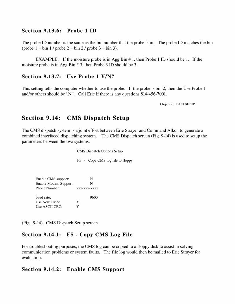
Section 9.13.6: Probe 1 ID
The probe ID number is the same as the bin number that the probe is in. The probe ID matches the bin (probe 1 = bin 1 / probe 2 = bin 2 / probe 3 = bin 3).
EXAMPLE: If the moisture probe is in Agg Bin # 1, then Probe 1 ID should be 1. If the moisture probe is in Agg Bin # 3, then Probe 3 ID should be 3.
Section 9.13.7: Use Probe 1 Y/N?
This setting tells the computer whether to use the probe. If the probe is bin 2, then the Use Probe 1 and/or others should be “N”. Call Erie if there is any questions 8144567001.
Chapter 9 PLANT SETUP
Section 9.14: CMS Dispatch Setup
The CMS dispatch system is a joint effort between Erie Strayer and Command Alkon to generate a combined interfaced dispatching system. The CMS Dispatch screen (Fig. 914) is used to setup the parameters between the two systems.
CMS Dispatch Options Setup
F5 Copy CMS log file to floppy
Enable CMS support: NEnable Modem Support: NPhone Number: xxxxxxxxxx
baud rate: 9600Use New CMS: YUse ASCII CRC: Y
(Fig. 914) CMS Dispatch Setup screen
Section 9.14.1: F5 Copy CMS Log File
For troubleshooting purposes, the CMS log can be copied to a floppy disk to assist in solving communication problems or system faults. The file log would then be mailed to Erie Strayer for evaluation.
Section 9.14.2: Enable CMS Support

This tells the computer whether to utilize the CMS system. Normally this will be “N”.
Section 9.14.3: Enable Modem Support
If the computer is not interconnected, the computer must dial up the dispatching computer or vice versa, depending on the setup. If there is an interconnecting cable between the computers, or if there is no CMS support, then the option is “N”.
Section 9.14.4: Phone Number
This tells the computer what telephone number to dial to access the other computer.
Section 9.14.5: Baud Rate
This tells the computer what speed the modem operates at. Check with the Manufacturer for detailed information. 8144567001
Chapter 9 PLANT SETUP
Section 9.14.6: Use New CMS
Command Alkon has an Old version and a New version of CMS dispatching systems. Check with the manufacturer for detailed information of your particular Control System.
Section 9.14.7: Use ASCII CRC
This is part of the setup parameters for the new version of Command Alkon Dispatching. Contact the manufacturer for more detailed information.

Chapter 10: DIAGNOSTICS
CHAPTER 10: DIAGNOSTICS
Diagnostics is the 3rd option in the Utilities submenu screen (Fig. 80, page 45). This option will display the Plant Test submenu screen (Fig. 100). Contained on this menu are selections for Read Plant Inputs and Scales, Test Plant Outputs, Initialize Time and Date, Print Common Area, and Adjust Simulated Moisture. An experienced technician can use these selections to test, troubleshoot, and monitor various functions of the control system.
SELECT TEST OPTION
1. READ PLANT INPUTS AND SCALES 2. TEST PLANT OUTPUTS 3. INITIALIZE TIME AND DATE 4. PRINT COMMON AREA 5. ADJUST SIMULATED MOISTURE
(Fig. 100) Plant Test submenu screen

Section 10.1: Read Plant Inputs and Scales
The computer will display the Read Plant Inputs and Scales screen (Fig. 101) displaying the current state of the plant. On the left side of the screen, will be a readout of each scale system on the batch plant. The computer will display what the current weight is on each of the scale. Beneath the scale system readouts will be the readouts for the Admix and Water Systems on the batch plant. The computer will display any counts from the meters that are registered by the computer while this screen is displayed. On the right side of the screen, the computer will display all of the inputs that the computer reads from the yellow Input Modules which are located in the I/O Interface Box. The computer will display what the current condition of that input is. An example would be the input for the Agg Batcher gate. The computer will either display Agg Discharge Open or Agg Discharge Close depending upon which condition is read.
Near the bottom of the screen the computer will display "DI /DO DATA =" followed by a string of letters and numbers. This is a representation of the current condition of the black Output and yellow Input Modules used in the system.
Chapter 10: DIAGNOSTICS
P L A N T I N P U T S
AGG DISCHARGE CLOSED POUNDS CMT DISCHARGE CLOSED
AGG SCALE 00000 WATER DISCHARGE CLOSED CMT SCALE 00000 WATER TANK EMPTY WAT SCALE 00000 SYSTEM = AUTO ICE SCALE 00000 CYCLE STOP = OFF AG2 SCALE 00015 TOL.ACCEPT = OFF AG3 SCALE 00030 CONVEYOR = RUNNING AG4 SCALE 00045 MIXER = HOME FLY SCALE 00000 ADMIX 1 = 0 (Empty) MIXER = RUNNING ADMIX 2 = 0 (Empty) POSITION=MIXER 1 ADMIX 3 = 0 (Empty) ADMIX 4 = 0 (Empty) ADMIX 5 = 0 (Empty) ADMIX 6 = 0 (Empty) ADMIX 7 = 0 (Empty) WATER = 0
DI/DO DATA = 82 04 a0 f2 00 00 00 fe 00 44 a0 e8
PRESS ESC TO EXIT

(Fig. 101) Read Plant Inputs and Scales screen
Section 10.2: Test Plant Outputs
The Erie Strayer Company has developed several diagnostic test procedures to assist the operator in determining if the problem is computer related or an electromechanical fault with the batch plant. The Test Plant Outputs diagnostic routine is the best tool the operator has to help troubleshoot suspected control system problems.
Before the Test Plant Outputs screen (Fig. 103) appears, the Cable Warning screen (Fig. 102) will be displayed.
WARNING: When in the Test Plant Outputs screen, it is possible to open any of the plant's gates or valves, feed water or admix, or operate any other output function of the control system. This warning is for protection against the loss of material and injury to personnel. When all the control cables are removed from the back of the manual panel, except for the main power cable from the Motor Control Panel, testing the Plant Outputs can be performed.
Chapter 10: DIAGNOSTICS
T E S T P L A N T O U T P U T S
WARNING !!
DISCONNECT ALL CABLES FROM THE COMPUTER JUNCTION BOXTO THE PLANT BEFORE RUNNING THIS PROGRAM.
DO YOU WANT TO TEST PLANT OUTPUTS (Y/N)
(Fig. 102) Cable Warning screen
NOTE: The Test Plant Outputs screen (Fig. 103) displays the Inputs from the batch plant and the Outputs from the computer to the batch plant. The pin numbers displayed in YELLOW letters on the screen mean the module pin number is an Input to the computer from the batch plant. The pin numbers displayed in BLACK letters on the screen mean the module pin number is an Output from the computer to the batch plant. When inputs or outputs are turned 'on' (energized), they are displayed with a green background. When inputs or outputs are turned 'off' (deenergized), they are displayed with a red background. Refer to the D19 drawing (Electrical Equipment Manual) titled "Pamux Board layout InputOutput Modules Interface" when using the Test Plant Outputs screen. The D19 drawing is a "road map" that enables the operator to correlate the function of the input or output module pin number with the correct pin number displayed on the Test Plant Outputs screen.

MAIN I/O1 pamux 2 pamux 3 pamux 4 pamux 5 pamux 6 pamux
Use spacebar to toggle, and arrow keys to navigate 0 16 32 48 64 80 +96 +112 +128 +144 +160 +176+1 17 33 49 65 81 +97 +113 +129 +145 +161 +1772 18 34 50 66 82 +98 +114 +130 +146 +162 +1783 19 35 51 67 83 +99 +115 +131 +147 +163 +1794 20 36 52 68 +84 +100 +116 +132 +148 +164 +1805 21 37 53 69 +85 +101 +117 +133 +149 +165 +1816 22 38 54 70 +86 +102 +118 +134 +150 +166 +182+7 23 39 55 71 +87 +103 +119 +135 +151 +167 +1838 +24 40 56 72 +88 +104 +120 +136 +152 +168 +1849 25 41 +57 73 +89 +105 +121 +137 +153 +169 +185+10 26 42 +58 74 +90 +106 +122 +138 +154 +170 +18611 27 43 +59 75 +91 +107 +123 +139 +155 +171 +18712 28 44 +60 76 +92 +108 +124 +140 +156 +172 +18813 29 45 +61 77 +93 +109 +125 +141 +157 +173 +18914 +30 46 +62 78 +94 +110 +126 +142 +158 +174 +19015 +31 47 +63 79 +95 +111 +127 +143 +159 +175 +191
s0= 0 s1= 2 s2= 13008 s3= 25000 S4= 86665 s5= 86665 s6= 86665 s7= 86665
(Fig. 103) Test Plant Outputs screen
Chapter 10: DIAGNOSTICS
When the desired pin number is determined from the D19 drawing, enter the number and press the "enter" key. When the test is finished, do not forget to turn the pin number "off". Once the pin number is turned "on", it must be turned "off" or it will stay on even when the Test Plant Outputs screen is exited.
Section 10.3: Set Time and Date
The Set Time and Date screen (Fig. 104) is straight forward, enter the numbers and press the "enter" key.
S E T T I M E A N D D A T E
Month : 8 Hours (24 hr) : 13Day : 3 Minutes : 18Year : 2000
(Fig. 104) Set Time and Date screen
Section 10.4: Print Common Area

The Print Common Area screen (Fig. 105) is used by the Erie programmers to verify the operation of modules inside the program. It serves no general use for the operator unless there is a control system problem and Erie asks for information from the screen.
time = 10:58:44NEW_SYSTEM_STATUS = MANUALCYCLE_STOP = 0SIMULATION = 1Accept Tolerance() = 0PROBE_TYPE = 0POSITION = 1CYCLE_STATUS = 0 READYBATCH_RESET = 0CENTRAL_START_ENABLE = 0ALL_MATLS = 0x510F001FWEIGH_CODE = 0x00000000DISCHARGE_ENABLE = 0DISCH_CODE = 0x00000000THREAD_CODE = 0x00000000MIXER_START_ENABLE[0] = 0MIXER_STATE[0] = 0 READYEARLY_DISCHARGE = 0USE_MIXER = 0AGG_STATE = 0, 0, 0, 0CMT_STATE[0] = 0,WAT_STATE = 0ICE_STATE = 0
(Fig. 105) Print Common Area screen
Chapter 10: DIAGNOSTICS
Section 10.5: Adjust Simulated Moisture This is used for testing purposes while running the control system in simulation only. The aggregate can be given a simulated moisture percent for testing. There is no other reason to access this screen.


THIS PAGE INTENTIONALLY LEFT BLANK
Chapter 11: FILE MAINTENANCE
CHAPTER 11: FILE MAINTENANCE
The File Maintenance submenu screen (Fig. 110) is displayed by selecting option #4 from the Utilities submenu screen (Fig. 80, page 45). This is the menu where all data information is saved or loaded. Call the Software Dept. at Erie Strayer Co. if there is any questions (814) 4567001.
NOTE: When the floppy drive is going to be used, it is advisable to
clean the drive first to ensure accurate data transfer.
File Maintenance
SELECT
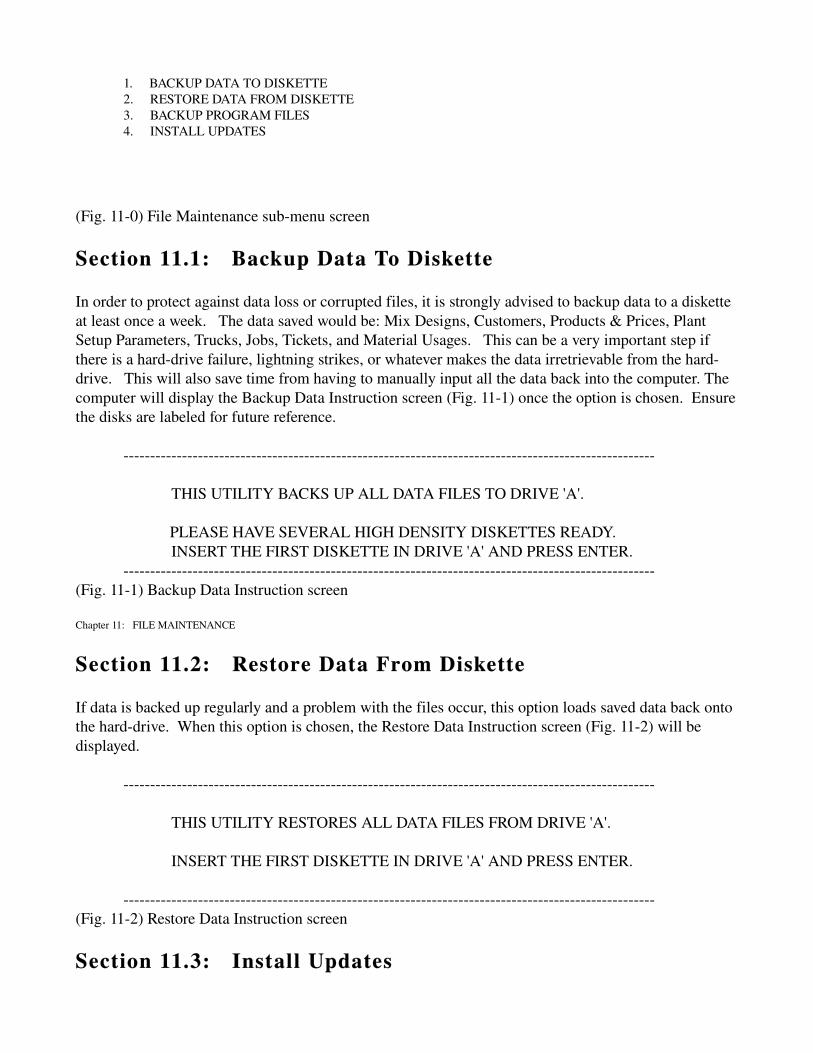
1. BACKUP DATA TO DISKETTE 2. RESTORE DATA FROM DISKETTE 3. BACKUP PROGRAM FILES 4. INSTALL UPDATES
(Fig. 110) File Maintenance submenu screen
Section 11.1: Backup Data To Diskette
In order to protect against data loss or corrupted files, it is strongly advised to backup data to a diskette at least once a week. The data saved would be: Mix Designs, Customers, Products & Prices, Plant Setup Parameters, Trucks, Jobs, Tickets, and Material Usages. This can be a very important step if there is a harddrive failure, lightning strikes, or whatever makes the data irretrievable from the harddrive. This will also save time from having to manually input all the data back into the computer. The computer will display the Backup Data Instruction screen (Fig. 111) once the option is chosen. Ensure the disks are labeled for future reference.
THIS UTILITY BACKS UP ALL DATA FILES TO DRIVE 'A'.
PLEASE HAVE SEVERAL HIGH DENSITY DISKETTES READY. INSERT THE FIRST DISKETTE IN DRIVE 'A' AND PRESS ENTER.
(Fig. 111) Backup Data Instruction screen
Chapter 11: FILE MAINTENANCE
Section 11.2: Restore Data From Diskette
If data is backed up regularly and a problem with the files occur, this option loads saved data back onto the harddrive. When this option is chosen, the Restore Data Instruction screen (Fig. 112) will be displayed.
THIS UTILITY RESTORES ALL DATA FILES FROM DRIVE 'A'.
INSERT THE FIRST DISKETTE IN DRIVE 'A' AND PRESS ENTER.
(Fig. 112) Restore Data Instruction screen
Section 11.3: Install Updates

When software problems or changes need addressed, this option is used for repairing/modifying the software on the harddrive. An Install Update Instruction screen (Fig. 113) will be displayed.
INSERT UPDATE DISKETTE IN DRIVE 'A' AND PRESS ENTER.
(Fig. 113) Install Update Instruction screen
Section 11.4: Backup Program Files
It is advisable to backup the Sentry program files for protection in case of harddrive problems or lightning strikes. Backup Program Files will do this. The Backup Program Files Instruction screen (Fig. 114) will be displayed. Ensure the disks are labeled for future reference.
THIS UTILITY BACKS UP ALL SENTRY PROGRAM FILES TO DRIVE 'A'.
PLEASE HAVE SEVERAL HIGH DENSITY DISKETTES READY.
INSERT THE FIRST DISKETTE IN DRIVE 'A' AND PRESS ENTER.
(Fig. 114) Backup Program Files Instruction screen
Chapter 12: DISPATCH (F8)
CHAPTER 12: DISPATCH (F8)
This option is for Erie Dispatching Systems. The Dispatch List screen (Fig. 121) shows what the dispatcher would see to send jobs to the desired plant for production.
DISPATCH LIST
TIME DATE CUST# JOB# DELIVER TO: LOADS TRUCK# MIX#13:38 11/14 JB10 32 219 Ellen Dr. Erie, PA 3 8 3000PSI13:58 11/14 6224 2 HWY 79, Girard, PA 2 3 FLOFIL

ENTER Modify Reco rd F6 Assign to PlantINS Add RecordDEL Delete Record ESC Exit
FILE CONTAINS 2 RECORDS
(Fig. 121) Dispatch List screen
When a specific job is highlighted, the “F6" key will display the Assign Plant screen (Fig. 122) in which the operator will assign the plant number. Each plant should have a separate plant number for identification purposes.
Which plant do you want to assign this batch to?
Plant number:
(Fig. 122) Assign Plant screen
After the dispatch computer has assigned a job to a specific plant, that specific plant will see the job in it’s Batch Queue screen. The Batch Queue screen displays the jobs for that plant to complete. The Batch Queue screen is identical to the Dispatch List screen (Fig. 121)
THIS PAGE WAS INTENTIONALLY LEFT BLANK
Chapter 13: BATCHING SYSTEM (F10)
CHAPTER 13: BATCHING SYSTEM (F10)
Section 13.1: Begin Weigh Cycle
"Begin Weigh Cycle" is the part of the program that makes concrete. The program will use all the given information to control the plant functions in loading a truck with concrete. It is the responsibility of the batch operator to monitor each load as it discharges into the truck to verify size, material, and all other requirements.

Section 13.2: Batch Setup
From the Main Menu screen, select Begin Weigh Cycle by pressing the "F10" key. The Batch Setup screen (Fig. 130) will be displayed first. On the left side of the screen, will be a column of entries to determine the parameters of the load to be batched. On the right, will be a column for entering who the load is for, where to deliver the load, and the Mix Design description. At the bottom of the screen are the options: Pricing Data, Adjustments for Moisture in the Agg, Adjustments for the Admix Dosages, Pre Batch Print Products, and the option to Clear Out the setup data.
Customer Number GL45 Sold To:Job Number 123 Johnson Const. Mix Number 3000
Batch Size 9.00 Returned 0.00
Deliver To: Water Trim 1.50 Millcreek MallIce 25 % Rear parking lot Truck 24 Driver Johnny
Description: Number of Cycles 1 3000 PSI Standard Print Weights? Y
PRESS F3 FOR CUSTOMER LISTF4 Pricing Data F5 Adjust Admix Dosages F6 Pre Batch PrintF7 Adjust Moisture Percentages F8 Clear out setup data
Use F12 to toggle between screens
(Fig. 130) Batch Setup screen
The pricing data option allows the operator to set pricing for that particular batch. It will clear after the batch is completed. The Adjust Admix Dosages option will adjust the admix amounts only for that batch, after the batch is complete, it will be cleared out. The Adjust Moisture Percentages options will set the moisture percent for the specified aggregates and WILL NOT
Chapter 13: BATCHING SYSTEM (F10)
clear out after the batch is completed. The moisture settings must be manually changed back to zero or the moisture settings will be influencing in every load batched. The Pre Batch Print option will print a ticket for other than concrete items (rebar, blocks, etc...). The Clear Out Setup Data will clear the batch setup screen data if the Paver option (Plant Parameters screen Fig. 98, page 75) is set to “Y”. Generally the screen will clear out after each batch.
Section 13.2.1: Batch Setup Entry Procedures
Section 13.2.1.1: Customer Number

The Customer Number is the same as the Customer ID from the Customer List screen (Fig. 69, page 28). It is an alphanumeric 8 character maximum input. Pressing the "F3" key will display the Customer List screen from which the operator may choose a customer.
NOTE: When a Job Number other than 00000000 is entered, the settings for the Mix Design Number and Customer Number can not be changed without going back to that Job # in the Job Entry screen. A Batch can be setup without a Job Number or Customer Number, by leaving them empty and entering a Batch Size and Mix Design Number for the load to be batched.
Section 13.2.1.2: Job Number
The Job Number is the same as the Job ID number in the Job List screen (Fig. 51, page 11). It is an alphanumeric 8 character maximum input. Pressing the "F3" key will display the Job List screen from which the operator may choose the job to be batched.
Section 13.2.1.3: Mix Design Number
The Mix Design Number tells the computer which Mix Design (Formula) to use for the load. It is an alphanumeric 8 character maximum input. It should already be setup through the Job Entry screen (Fig. 53, page 13). Pressing the "F3" key will display the Mix Design List screen (Fig. 61, page 18) from which the operator may choose a Mix Design to use.
Section 13.2.1.4: Batch Size
Sets the size of the load to be batched. It can not be larger than the Plant Capacity or Maximum Load displayed in the Plant Parameters screen (Fig. 98, page 75). It will already be setup through the Job Entry screen (Fig. 53, page 13) but can be changed if required.
Section 13.2.1.5: Returned
If returned concrete is being used, this is the input for the amount of concrete that is already in the truck. The computer will automatically calculate the size of the load to be weighed and discharged to equal the Batch Size of the load.
Chapter 13: BATCHING SYSTEM (F10)
NOTE: When batching concrete with returned concrete, the computer
will NOT print the weights on the ticket.
EXAMPLE: A truck has 2 yards of concrete when it returns. A customer wants 10 yards of concrete. The operator enters 10.00 for Batch Size and 02.00 for Returned. The computer will batch 8 yards of concrete and print a Ticket with 10 yards displayed.

Section 13.2.1.6: Water Trim
To add or subtract water from the load, the operator may enter an amount in gallons per yard. Insert a negative number to withhold, or a positive number to add.
Section 13.2.1.7: Ice
If the plant has an Ice system, this is where a percentage of the total water for the load is set to be ice. It will display the Ice Default Pct. per the Ice Batcher Setup (Chpt 9, page 80), but can be changed for a particular load.
Section 13.2.1.8: Truck Number
The Truck Number tells the computer which truck is being used so it can adjust the discharge rate per the Truck Record screen (Fig. 65, page 23). Each truck is different and may have different speeds in which it can take material. If no rate is given in the Truck Record, the computer will discharge per the Discharge Sequence setting in the Plant Setup.
NOTE: If material is plugging up in the truck charging chute during discharge, it may be because the discharge rate in the truck record needs adjusted.
Section 13.2.1.9: Driver ID
When the Truck Number is entered, the Drivers Name should appear under the Truck Number. The Driver Name is set in the Truck Record screen (Fig. 65, page 23).
Section 13.2.1.10: Cycles
"Cycles" allows the operator to tell the computer how many times the load is to be batched in a row. Up to 999 cycles may be entered by the operator.
Section 13.2.1.11: Sold To
"Sold To" is the name of the customer that is being billed for the material. This should already be entered from the Job Entry screen (Fig. 53, page 13), if the Job Number was entered.
Chapter 13: BATCHING SYSTEM (F10)
Section 13.2.1.12: Deliver To
"Deliver To" is the address where the material is to be delivered. This should already be entered from the Job Entry screen (Fig. 53, page 13), if the Job Number was entered.
Section 13.2.1.13: Description

The Description displays what was entered in the Mix Design screen (Fig. 62, page 18) for the Mix Design description.
After the cursor has been moved to each position, the operator will see "Changes (Y/N)?" near the bottom of the screen. A "Y" response will move the cursor back up to the Job Number where the operator may move the cursor to any position desired and make a change. An "N" response will clear the screen and display the Cycle screen (Fig. 131).
Section 13.3: Cycle
The Cycle screen (Fig. 131) is where the operator starts and monitors the Weighing and Discharge Cycles. The top of the page, in blue, displays the Customer, Mix Design, Truck, Batch Size, Job Number, how many Cycles, and the Deliver To address.
The materials will be displayed at the bottom of the page in red. The Aggregates will be displayed on the lower left of the screen, the Cement is in the lower center and the Water and Admix are on the lower right, all with bin numbers and target weights/amounts next to them. The computer will also display various commands and messages in the center of the screen. By following these commands and messages, the operator will be able to control the batching process and detect incorrect settings and malfunctions in both the computer and the plant.
2/15/00 13:24:14
Sold To: GL45 Deliver To: Job: 123 Johnson Const. Millcreek Mall Batch Size: 9.00
Rear parking Cycles: 1lot
Mix Number: 3000 Ticket # 000593
Description: Truck: 24 3000 PSI Standard Driver Johnny Loads Shipped 1
Yards Shipped 9.00 US UNITS
USE F12 TO TOGGLE BETWEEN SCREENSCENTRAL START READY (F2)
AGG1 SAND 10800 CMT1 TYPE I 5076 WAT 225 AGG2 ½ ST 27000 CMT2 FLY 6176
ADM1 AEA 180AGG = 0 CMT = 0
(Fig. 131) Cycle screen
Chapter 13: BATCHING SYSTEM (F10)
Section 13.3.1: Weighing Cycle
The computer will determine if the load "called for" is within the parameters of the Mix Design, Plant Setup, Job and Customer files, that were previously set. If any condition exists which falls outside of

the parameters set, the computer will display an error message in the center of the screen.
EXAMPLE: “CMT EXCEEDS SCALE CAPACITY” The computer has determined the amount of cement called for in the load to be batched is a higher number than the setting entered for Scale Capacity in Cement Batcher Setup.
The computer then determines if all the interlocks from the plant are satisfied. If any condition exists where an interlock is not set correctly, the computer will display an error message in the center of the screen.
EXAMPLE: “AGG DISCHARGE GATE OPEN” The computer found the input from the plant indicated the Agg batcher discharge gate was open. This is a condition that will prevent you from continuing the batching process and must be corrected before you can continue.
If all conditions are met, the computer will display in the center of the screen "CENTRAL START READY (F2)". When the "F2" key is pressed, the computer will start the batching process with the Weighing Cycle (Fig. 132).
On the lower left of the screen, the name of the aggregates, the bin #'s, the target weights and actual weights will all be displayed. The name will correspond to the setting for the Name in Aggregate Setup (Chpt 9, page 63) and the Material List (Chpt 6, page 30). The order of weigh up for each aggregate will be determined by the order it was entered in the Mix Design. The target weight will be what the computer has calculated based on the Mix Design, Batch Size, and Moisture settings for the aggregates.
On the lower center of the screen, the name of the cements, the bin #'s, the target weights and the actual weights will be displayed. This is done in the same manner as the aggregates. (Reference Cement Setup Chpt 9, page 66)
On the lower right of the screen, the Water and target amount will be displayed. When the water starts, the actual amount will be displayed to the right of the target amount. Under the Water will be the name of the Admixtures being batched, the # of the bottle, the target amount of the Admix and the actual amount metered. The Admix name will correspond to the setting for Name in the Admix Setup (Chpt 9, page 61) and Material List (Chpt 6, page 30). The target amount will be determined by the computer according to the Mix Design and Batch Size.
Chapter 13: BATCHING SYSTEM (F10)
During the Weighing Cycle, the computer will display various messages for the operator by Word or Letter. The Word will be either Under, Balance, Jogging, Complete or Over. The Letter will be either U, B, J, C or O. These Words and Letters will show the status of each material during the Weighing Cycle.
Under or U, indicates that the minimum target weight or amount has not yet been reached as determined by the tolerance settings in the Plant Setup files and Mix Design.

Balance or B, indicates a pause between a Fast Feed and a Jog, and between successive Jogs. The length of this pause is determined by the setting of the Scale Balance Time.
Jogging or J, indicates a Jog. Each Jog will be followed by a Balance.
Complete or C, indicates the target weight or amount has been reached as determined by the over and under tolerances set for each material.
Over or O, indicates that the target weight or amount has exceeded the maximum allowed for the over tolerance for that material. When an Over is displayed, the operator must note how far over the target weight the material is, and then make a decision on whether to accept the amount or not. If the operator feels that the additional amount of material will not hurt the concrete, the Accept Key located on the Manual Panel must be turned on for a minimum of 2 seconds. If the operator feels that the additional material will hurt the concrete, the additional material must be removed before continuing. In all cases, the batching process will not continue in Automatic if an Over or O is displayed on the screen.
At the start of the Weighing Cycle, the computer will display the Fill Time on the right of the screen. The computer will keep track of how long it takes to weigh up the load. In this manner, the operator can monitor the Fill Time to notice changes that may cause loss of production time.
At the top of the screen throughout the batching cycle, the computer will display the status of the mixer (if applicable).
Chapter 13: BATCHING SYSTEM (F10)
2/15/00 13:24:14 Fill Time 00:16

Sold To: GL45 Deliver To: Job: 123Johnson Const. Millcreek Mall Batch Size: 9.00
Rear parking Cycles: 1lot
Ticket # 000593Mix Number: 3000
Description: Truck: 243000 PSI Standard Driver Johnny Loads Shipped 1
Yards Shipped 9.00 US UNITS
USE F12 TO TOGGLE BETWEEN SCREENS
PRESS F2 TO START WATER
AGG1 SAND 10800 5720 CMT1 TYPE I 5076 4863 WAT 225 AGG2 ½ ST 27000 CMT2 FLY 6176
ADM AEA 180 122
AGG = 5720 FAST FEED CMT = 4863 BALANCE
(Fig. 132) Weighing Cycle screen
Chapter 13: BATCHING SYSTEM (F10)
When all of the materials for the load has been weighed up, the computer will display "BATCH COMPLETE" in the center of the Cycle screen (Fig. 133). Immediately following this, the computer will display "DISCHARGE READY (F2) " in the center of the screen. The operator may then press the "F2" key to start the Discharge Cycle.
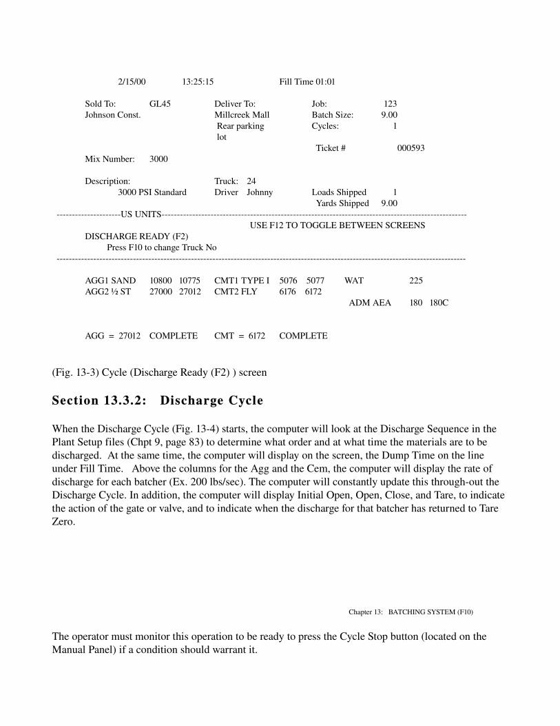
2/15/00 13:25:15 Fill Time 01:01
Sold To: GL45 Deliver To: Job: 123Johnson Const. Millcreek Mall Batch Size: 9.00
Rear parking Cycles: 1lot
Ticket # 000593Mix Number: 3000
Description: Truck: 243000 PSI Standard Driver Johnny Loads Shipped 1
Yards Shipped 9.00 US UNITS
USE F12 TO TOGGLE BETWEEN SCREENSDISCHARGE READY (F2)
Press F10 to change Truck No
AGG1 SAND 10800 10775 CMT1 TYPE I 5076 5077 WAT 225AGG2 ½ ST 27000 27012 CMT2 FLY 6176 6172
ADM AEA 180 180C
AGG = 27012 COMPLETE CMT = 6172 COMPLETE
(Fig. 133) Cycle (Discharge Ready (F2) ) screen
Section 13.3.2: Discharge Cycle
When the Discharge Cycle (Fig. 134) starts, the computer will look at the Discharge Sequence in the Plant Setup files (Chpt 9, page 83) to determine what order and at what time the materials are to be discharged. At the same time, the computer will display on the screen, the Dump Time on the line under Fill Time. Above the columns for the Agg and the Cem, the computer will display the rate of discharge for each batcher (Ex. 200 lbs/sec). The computer will constantly update this throughout the Discharge Cycle. In addition, the computer will display Initial Open, Open, Close, and Tare, to indicate the action of the gate or valve, and to indicate when the discharge for that batcher has returned to Tare Zero.
Chapter 13: BATCHING SYSTEM (F10)
The operator must monitor this operation to be ready to press the Cycle Stop button (located on the Manual Panel) if a condition should warrant it.

2/15/00 13:25:20 Fill Time 01:01 Dump Time 00:05
Sold To: GL45 Deliver To: Job: 123Johnson Const. Millcreek Mall Batch Size: 9.00
Rear parking Cycles: 1lot
Ticket # 000593Mix Number: 3000
Description: Truck: 243000 PSI Standard Driver Johnny Loads Shipped 1
400 lbs / sec 75 lbs / sec Yards Shipped 9.00 US UNITS
USE F12 TO TOGGLE BETWEEN SCREENS
F1 SETUP NEXT BATCH
AGG1 SAND 10800 10775 CMT1 TYPE I 5076 5077 WAT 225 200HAGG2 ½ ST 27000 27012 CMT2 FLY 6176 6172
ADM AEA 180 180
AGG = 27012 PULSE OPEN CMT = 6172 PULSE CLOSE
(Fig. 134) Cycle (Discharge Cycle) screen
Section 13.3.3: Next Batch Setup
During the Discharge Cycle the computer will display near the center of the Cycle screen (Fig. 134) "F1 SETUP NEXT BATCH". The operator has the option to set up the next batch before the current load is complete. When "F1" is pressed, the Batch Setup screen (Fig. 130) is displayed. Once the parameters are entered into the Batch Setup screen, the computer will go back to the Cycle screen and await the completion of the load.
Section 13.3.4: Discharge Complete
Depending upon how the Discharge Sequence is setup (Mixer Controls, Chpt 9, page 74), the computer will display the mix time at the top of the screen when all the materials are in the mixer or when all the solids are in the mixer.
Chapter 13: BATCHING SYSTEM (F10)
When the plant is finished discharging all the materials into the mixer/truck, the Cycle screen will display "Discharge Complete" (Fig. 135). After the screen displays Discharge Complete, it will display

"Printing Ticket" (Cycle screen Fig. 136) to let the operator know a ticket will be made of the last load batched.
The computer will go back to the Main Menu unless "F1" was pressed to setup another batch, in which it will display the Cycle screen (Fig. 131).
2/15/00 13:27:13 Fill Time 01:01 Dump Time 01:58
Sold To: GL45 Deliver To: Job: 123Johnson Const. Millcreek Mall Batch Size: 9.00
Rear parking Cycles: 1lot
Ticket # 000593Mix Number: 3000
Description: Truck: 243000 PSI Standard Driver Johnny Loads Shipped 1
Yards Shipped 9.00 US UNITS
USE F12 TO TOGGLE BETWEEN SCREENSDISCHARGE COMPLETE
AGG1 SAND 10800 CMT1 TYPE I 5076 WAT 225 225CAGG2 ½ ST 27000 CMT2 FLY 6176
ADM AEA 180 180
AGG = 0 TARE ZERO CMT = 0 TARE ZERO
(Fig. 135) Cycle screen (Discharge Complete)
Chapter 13: BATCHING SYSTEM (F10)

2/15/00 13:27:36 Fill Time 01:01 Dump Time 02:21
Sold To: GL45 Deliver To: Job: 123Johnson Const. Millcreek Mall Batch Size: 9.00
Rear parking Cycles: 1lot
Ticket # 000593Mix Number: 3000
Description: Truck: 243000 PSI Standard Driver Johnny Loads Shipped 1
Yards Shipped 9.00 US UNITS
USE F12 TO TOGGLE BETWEEN SCREENSPRINTING TICKET
AGG1 SAND 10800 CMT1 TYPE I 5076 WAT 225 225CAGG2 ½ ST 27000 CMT2 FLY 6176
ADM AEA 180 180
AGG = 0 TARE ZERO CMT = 0 TARE ZERO
(Fig. 136) Cycle screen (Printing Ticket)
If the computer will not display "Discharge Complete", then the computer is waiting for something to finish. Call the Software Dept. at Erie Strayer Co. (8144567001) if the problem continues.

THIS PAGE WAS INTENTIONALLY LEFT BLANK

Chapter 14: MANUAL OPERATION
CHAPTER 14: MANUAL OPERATION
The Sentry Control System is capable of complete manual mode operation of the batch plant from the Manual Control Panel. The operator can control any and all functions of the Batch Plant. The Manual Control Panel is a color coded pushbutton panel and offers compact ease of operation.
The Manual Control Panel comes in two versions: Transit Mix and Central Mix. The Transit Mix Manual Control Panel is used when the system is installed on a Transit Mix (Dry Batch) plant. On the face of the panel are pushbuttons, key switch(s) and rotary controls that are divided into Feed Controls, Batcher Controls, Motor Controls and Miscellaneous Controls.
The Feed Controls control the weighup or metering of materials into batchers or holding containers. The Feed Control pushbuttons will be color coded yellow and are known as momentary pushbutton switches. When the appropriate button is pushed, an electrical signal is sent. When the button is released, the electrical signal stops. This signal is used to control solenoid air valves or motor starters. In the case of air valves, either a gate or valve opens which in turn causes the selected material to pass. In the case of a motor starter, a device such as a screw starts. This is used to convey material from point A to point B.
When batching in manual mode, all materials are dependant upon the operator for required weights and measures. The Central Mix Manual Control Panel is essentially the same as the Transit Mix panel with the exception that it also contains controls for the operation of the central mixer. These controls consist of hydraulic start/stop and mixer drive start/stop control. Also included are mixer tilt and return switches, auto/manual mixer control switch, and associated lights to indicate the position of the mixer. The panel contains a speed control dial for controlling the tilt speed of the mixer drum.
This chapter will give the operator definitions for the manual pushbuttons and switches found on the Manual Control Panel. Remember, this Manual may give definitions for pushbuttons and switches that are not found on every Manual Control Panel.
Section 14.1: Main Power & Control Switch Functions
Main Power On Keyswitch This keyswitch powers the manual control panel. When “on”, the incoming control power wires (labeled 13L1, 14L1, 15L1, and 16L1) will read 115 VAC with respect to neutral (L2) or ground.
Automatic / Manual switch This two position switch allows manual operation of the batch plant (Manual Mode) or provides computer control of the plant (Automatic Mode). Switching from Automatic Mode to Manual Mode
Chapter 14: MANUAL OPERATION

during an automatic batching cycle will interrupt the cycle, disconnecting the computer from the plant control functions. No ticket will be printed; no record of the batch will be recorded.
Tolerance Accept Keyswitch While batching in Automatic Mode, if an overweight of any weighed or metered material should occur, that overweight condition can be accepted by the operator by turning the Tolerance Accept Keyswitch. After accepting the overweight condition, the computer will resume the automatic batching cycle. If the operator does not want to accept the overweight condition, he would have to turn the Inspect keyswitch and adjust his weights manually by removing some of the material to bring the load into tolerance. Switching the Inspect keyswitch back to the normal position will resume automatic batching.
Cycle Stop Pushbutton The Cycle Stop button is a maintain, lighted pushbutton switch. Pressed in the Automatic mode will stop the computer from batching halting all computer functions. No Manual Panel pushbutton switches (feeds, open or close) will function in Cycle Stop Mode. Cycle Stop does not stop motors!
Inspect Keyswitch The Inspect Keyswitch allows the operator to halt all automatic batching and perform manual functions and then return to the batch cycle without losing the ticket or recordation. This feature is used for making minor adjustments to a load while batching in Automatic Mode.
Recycle Start switch If provided, this two position, maintained contact switch is primarily used by Paving Plants for repeated loads of the same mix design. The function of the Recycle Start switch is to automatically start weighing material for another load once all material has discharged scales are at tare zero and admixture bottles are empty. The computer will NOT automatically discharge the material. See Recycle Discharge.
Recycle Discharge switch If provided, this two position, maintained contact switch is primarily used by Paving Plants for repeated loads of the same mix design. The function of the Recycle Discharge switch is to automatically discharge the load when all the
Chapter 14: MANUAL OPERATION
materials are weighed or metered. The computer does not automatically discharge the material if the mixer is not ready to receive the load.
Section 14.2: Motor Switch Functions
Batch Transfer Conveyor Start/Stop This three position switch is a momentary contact with a spring return to center. When turned to the right, the batch transfer conveyor will start; when turned to the left, the conveyor will stop. Always be sure that personnel are clear of the conveyor before starting.
Air Compressor Start/Stop This three position switch is a momentary contact with a

spring return to center. When turned to the right, the air compressor will start; when turned to the left, the compressor will stop Most Air Compressors sold by Erie Strayer are set up to run continuously from the unloader valve.
Aeration Blower Start/Stop If provided, this three position switch is a momentary contact with a spring return to center. When turned to the right, the aeration blower will start running; when turned to the left, the blower will stop. Typical aeration blower pressure is preset from 3 to 5 PSI. Never adjust the popoff safety relief valve to increase air pressure!
Water Pump Start/Stop If provided, this three position switch is a momentary contact with a spring return to center. When turned to the right, the water pump will start running; when turned to the left the water pump will stop running. The pump will automatically shutoff (by means of a low level float switch) if the storage tank is empty. Never run the water pump dry!
Mixer Drive Start/Stop If provided, this three position switch is a momentary contact with a spring return to center. When turned to the right, the mixer drum will start to rotate; when turned to the left, the mixer drum will stop. Before starting the drum, check to make sure all personnel are clear of the mixer. On a new startup, or after power wiring changes, always be sure to phase each motor separately to insure correct rotation of the mixer drum.
Chapter 14: MANUAL OPERATION
Mixer Hydraulic Start/Stop If provided, this three position switch is a momentary contact with a spring return to center. When turned to the right, the hydraulic pump will start running; when turned to the left , the hydraulic pump will stop. Always insure personnel are clear of the mixer before tilting and returning the mixer drum.
Bin Charging Conveyor(s) Start/Stop If provided, this three position switch is a momentary contact with a spring return to center. When turned to the right, the Bin Charging Conveyor will start running; when turned to the left, the conveyor will stop. Always be sure personnel are clear of the bin charging conveyor before starting.
Filter Vent(s) Start/Stop If provided, this three position switch is a momentary contact with a spring return to center. When turned to the right, the Filter Vent will start operating; when turned to the left, the filter vent will stop.
Aeration switch(s) These toggle switches are maintained contact. When turned on, they will aerate the material in the cement or flyash storage compartment. Erie recommends turning on the aeration ½ hour before batching to help “fluff” the material for faster flow.
NOTE The cement batcher aeration only turns on when the cement discharge valve is opened (an automatic function).
Mixer Automatic / Manual switch The Mixer Automatic / Manual switch is a two position selector switch.

In the Manual position: the Mixer Tilt and Mixer Return pushbuttons can be activated at any time. The Timed Out light will only go out when the mixer reaches the top limit switch position.
In the Automatic position: the mixer can only be tilted after the Timed Out light comes on. Once the Mixer Tilt switch is momentarily pressed by the operator, the mixer will raise automatically to the full tilt position. The Timed Out light will turn off. After a programmed full tilt timer expires, the mixer
Chapter 14: MANUAL OPERATION
will return automatically to the returned (home) position..
Nose Plug Automatic / Manual switch The Nose Plug Automatic / Manual control is a maintained contact toggle switch.
In the Nose Plug Manual mode, the operator moves the nose plug in or out as needed using the Nose Plug In / Out switch.
In the Nose Plug Automatic mode, the nose plug moves out automatically when the mixer Tilt pushbutton is pressed. The mixer will not tilt until the nose plug is fully out. The nose plug will not move back into position until the mixer is being charged with another load. When the aggregate discharge gate opens, the nose plug will move into position automatically.
Nose Plug In / Out switch The Nose Plug In / Out is a momentary contact, spring return to center toggle switch. In the Nose Plug Manual mode, the nose plug is moved in or out solely by the plant operator. The electrical controls are interlocked so the nose plug must be in the out position prior to mixer tilt.
Section 14.3: Aggregate Section
Aggregate Vibrator Pushbutton The Aggregate Vibrator switch is a momentary contact pushbutton. Use the vibrator in moderation. It is designed to increase material flow from the scale. Prolonged vibrator use can cause scale weld failures.
Aggregate Feed Pushbutton This switch is a momentary contact pushbutton. Depressing it will feed aggregate out of the aggregate bin into the aggregate scale. The switch has no

“inching control” for cylinder operation. The aggregate feed cylinders are either fully open or fully closed. If material hangs up in the bin, opening and closing the gates several times, by pressing and releasing the aggregate feed switch, can free up the material for normal flow.
Chapter 14: MANUAL OPERATION
Aggregate (1) / ( 2) Open Pushbutton This switch is a momentary contact pushbutton. The solenoid valve that it activates is “double acting” for “inching control.” When pressed, the aggregate gate will partially open. Continued pressing of the switch will further open the gate. This “inching control” feature helps regulate the discharge flow of the aggregate onto the conveyor belt by adjusting the gate opening. Limit switches, activated by the gate, activate indicator lights on the Manual Panel for gate opened or closed position. The closed position limit switch provides an input to the computer for automatic operation. The aggregate gate must be closed for the computer to automatically weigh a load.
Aggregate (1) / (2) Close Pushbutton This switch is a momentary contact pushbutton. The solenoid valve that it activates is “double acting” for “inching control.” When pressed, the aggregate gate will partially close. Continued pressing of the switch will further close the gate. This “inching control” feature helps regulate the discharge flow of the aggregate onto the conveyor belt or into the truck or mixer by adjusting the gate closing. Limit switches, mechanically activated by the gate, operate indicator lights on the Manual Panel for gate opened or closed position. The closed position limit switch provides an input to the computer for automatic operation. The aggregate gate must be closed for the computer to automatically weigh a load.
Aggregate Batcher Open / Closed Lights These neon lights indicate the open or close status of the aggregate scale gates. The computer will not allow automatic weigh up of aggregate into the scale unless the closed light is on.
Section 14.4: Cement Section
Cement Vibrator Pushbutton The Cement Vibrator switch is a momentary contact pushbutton. Use the vibrator in moderation. It is designed to increase material flow from the scale. Prolonged vibrator use can cause scale weld failures.
Chapter 14: MANUAL OPERATION
Cement Feed Pushbutton This switch is a momentary contact pushbutton. Depressing it will feed cement out of the silo or bin into the cement scale. The switch has no “inching control”capability. The cement feed butterfly valves are either fully open or fully closed. If material

hangs up in the bin, opening and closing the valves several times, by pressing and releasing the cement feed switch, can free up the material for normal flow.
Cement (1) / ( 2) Open Pushbutton This switch is a momentary contact pushbutton. The solenoid valve that it activates is “double acting” for “inching control.” When pressed, the cement butterfly discharge valve will partially open. Continued pressing of the switch will further open the valve. This “inching control” feature helps regulate the discharge flow rate of the cement by adjusting the valve opening. A limit switch, mounted on the butterfly valve actuator, activates indicator lights on the Manual Panel for valve opened or closed position. The closed position limit switch provides an input to the computer for automatic operation. The cement batcher discharge valve must be closed for the computer to automatically weigh a load. When the cement butterfly valve is opened, an electrical signal from the limit switch turns on the aeration solenoid valve to aerate the scale automatically.
Cement (1) / (2) Close Pushbutton This switch is a momentary contact pushbutton. The solenoid valve that it activates is “double acting” for “inching control.” When pressed, the cement butterfly discharge valve will partially close. Continued pressing of the switch will further close the valve. This “inching control” feature helps regulate the discharge flow of the cement into the truck or mixer by adjusting the gate closing. Limit switches, mounted on the butterfly valve actuator, activate indicator lights on the Manual Panel for opened or closed position. The closed position limit switch provides an input to the computer for automatic operation. The cement discharge valve must be closed for the computer to automatically weigh a load.
Chapter 14: MANUAL OPERATION
Cement Batcher Open / Closed Lights These neon lights indicate the open and close status of the cement scale butterfly discharge valve. The computer will not allow automatic weigh up of cement unless the closed light is on.
Section 14.5: Water Section
Water Feed Pushbutton (Fast Feed) The Fast Water Feed switch is a momentary contact pushbutton. When activated, it feeds water through the larger water line. The counter on the Manual Panel must be turned to the WAT position to indicate the number of water count pulses from the water meter.
Water Feed Pushbutton (Slow Feed) The Slow Water Feed switch is a momentary contact pushbutton. When activated, it feeds water through the smaller water line. The counter on the Manual Panel must be turned to the WAT position to indicate the number of water count pulses from the water meter.
Section 14.6: Admixture Section
Admixture Feed Pushbutton The Admixture Feed switch is a momentary contact pushbutton. Set the rotary position selector switch to the Admixture bottle number that is to be used either into a bottle or directly into a truck or mixer. When the feed switch is pressed, that admixture will feed and the meter pulse counts will be reflected on the counter.
Admix Discharge Pushbutton There are separate maintained pushbuttons for each admixture bottle. Once an admixture is fed into a bottle, the operator can discharge the bottle by pressing its corresponding discharge pushbutton. The pushbutton is lighted to show when it is pressed. The operator must press the discharge button again to release it when the admixture bottle is empty and the bottle empty light comes on.
Admix Empty light The neon admixture bottle empty light on the manual control panel corresponds to the admixture bottle number that is selected on the selector switch. When the bottle empty probes in the admixture
Chapter 14: MANUAL OPERATION
bottle indicate that bottle is empty, the bottle empty light on the manual panel will turn on.
Section 14.7: Mixer Section
Mixer Timed Out light The neon indicator light is energized after the preselected mix time, set in the computer, has timed out. The Timed Out light goes out after the mixer is raised to the full tilt position.
Mixer Tilt Pushbutton In the Mixer Manual mode, the momentary contact pushbutton tilts the mixer when pressed. Releasing the pushbutton stops mixer tilt. There are mechanical stops and an electrical interlock that stop the mixer tilt when it reaches the full tilt position.
Mixer Tilt light The neon light comes on any time the mixer is raised off the bottom (home) limit switch. The light goes out when the mixer is fully returned.
Tilt Speed potentiometer The tilt speed of the mixer can be regulated by the Tilt Speed potentiometer. In the fully counterclockwise position, the mixer will not tilt in either the automatic or manual mode. In the fully clockwise position, the mixer will tilt at maximum speed. It is the responsibility of the operator to tilt the mixer at a sufficient rate to discharge the concrete from the mixer drum without choking the charging chute of the mixer truck.
Mixer Return Pushbutton In the Mixer Manual mode, the momentary contact pushbutton returns the mixer when pressed. Releasing the pushbutton stops mixer return. There are mechanical stops and an electrical interlock that stop the mixer return when it reaches the fully returned (home) position.

Mixer Return light The neon light comes on any time the mixer is fully returned or ‘home.” The light goes out anytime the mixer is tilted.
Chapter 14: MANUAL OPERATION
Section 14.8: Miscellaneous Switches or Pushbuttons
Horn Pushbutton If provided, this momentary pushbutton switch can be used for any purpose (load complete / truck clear to leave / truck in position / clear personnel away from plant / etc...)

Chapter 15: SYSTEM SHUTDOWN
CHAPTER 15: SYSTEM SHUTDOWN
The Sentry Control System uses a Linux based operating system. The Linux operating system is a multitasking, multifunction system which continuously has multiple programs running, including the Sentry Software. Because of the multiple running programs, the system MUST be shutdown properly.
To shutdown (quit) the Sentry Software the operator must type "halt" at the "Select Command:" prompt in the Main Menu screen.
NOTE: The "halt" command must be in lower case letters or the Linux operating system will not recognize it.
The system will begin shutdown procedures. When "System Shutdown" is displayed it is okay to turn the computer off.
WARNING: If the Sentry Control System is not shutdown properly, data files may become corrupt and cause problems batching and storing information. Please shutdown properly every night.

THIS PAGE INTENTIONALLY LEFT BLANK

Chapter 16: TROUBLESHOOTING
CHAPTER 16: TROUBLESHOOTING
The Sentry / Scout software can create problems that effect the operation of the program. The biggest problem is when the computer is not shutdown properly, files can become corrupted or unusable.
The first step in troubleshooting any software problem, is to always reboot the computer first. More than half of the problems will be solved this way.
Section 16.1: Cycle Screen Flags
In the Cycle screen (Fig. 131, page 104), several “flags” can pop up in the center of the screen if the plant or control system is not setup properly to batch.
“SYSTEM IS IN MANUAL” This flag tells the operator that the Auto/Manual button is in the manual position. The system will not batch automatically while in manual mode.
“CYCLE STOP IS ON” The Cycle Stop flag tells the operator that the Cycle Stop button is on, this places the system in a manual mode. The system will not batch automatically while in a manual mode.
“CONVEYOR NOT RUNNING” If the Batch Transfer Conveyor (BTC) is not running, the computer obviously can not discharge material onto it. This will halt batching until fixed.
“BATCH TOO BIG FOR TRUCK” If the operator is trying to batch a load that is too big than the Maximum Load parameter setting in the Plant Parameter screen (Fig. 98, page 75), the computer will not automatically batch.
“WATER EXCEEDS MAXIMUM” In the mix design, there is an option to set Max

Water. If the water being called for is more than the Max Water, this flag appears.
“AGG SCALE NOT AT TARE ZERO” In Plant Setup, the operator sets the Tare Zero for a scale. If the amount on the scale is more than the Tare Zero setting, the flag will appear.
Chapter 16: TROUBLESHOOTING
“CEMENT SCALE NOT AT TARE ZERO” In the Plant Setup, the operator can set the Tare Zero for a scale. If the amount reflected on the scale is more than the Tare Zero setting, the flag will appear.
“AGG DISCHARGE GATE OPEN” If an aggregate scale gate is opened, the computer will not feed material because the material would just fall through the scale. The gate must be closed before automatic batching is allowed.
“CMT DISCHARGE GATE OPEN” If a cement scale gate is opened, the computer will not feed material because the material would just fall through the scale. The gate must be closed before automatic batching is allowed.
“ADMIX (x) BOTTLE NOT EMPTY” If an Admix bottle is not empty, the computer will not feed material into the bottle. The bottle must be emptied before automatic batching is allowed.
Some of these flags may be the result of something other than it states. The computer receives an input from the plant for some of these flags. For example, the BTC could be running, but the computer reflects a “CONVEYOR NOT RUNNING” flag. The Pamux Board receives a signal from the plant when the conveyor is running, if that signal (wire X39) is not there, the computer will think the BTC is not running. Check the plant’s specific electrical schematics for troubleshooting. Call Erie Strayer Co. for assistance, if needed. 8144567001
Chapter 16: TROUBLESHOOTING

Section 16.2: Simulation Mode
For training purposes, the control system can be operated in a training mode where the plant is not functioning. In simulation, the only thing operating is the Sentry Control System. When batching in simulation, the computer does not know the plant is not being used. Material usages will be deducted from inventory even though the material is not removed.
Keep all simulated tickets for recordation purposes and inventory adjustments.
To enter into simulation mode, type stop at the Select Command prompt in the Main Menu screen and press the “enter” key.
At the # prompt, type killall cycle and then press the “enter” key
Next, type main s and then press the “enter” key. This will load the main program but in simulation mode.
When done with simulation mode, the same procedures would be typed in to return to the main program except the last step would be just main to reload the main program.
If there is any questions, please call Erie Strayer Co. 8144567001
Section 16.3: Ticket Spooling
If the printer is offline or not connected to the computer when batching, the computer will store the tickets in the print spooler to be printed later when a printer is connected. If the tickets are not required, the ticket spooler can be emptied so the printer will not print the backed up tickets.
Before turning the printer on, type stop at the Select Command prompt in the Main Menu and then press the “enter” key (observe lower case lettering).
At the # prompt, type lprm and then press the “enter” key Notice the space between lprm and the
Next, type main at the # prompt to return to the main program.
The tickets have been cleared from the spooler only. Each ticket can be individually reprinted from the Ticket Maintenance screen (Fig. 620, page 36).

Chapter 16: TROUBLESHOOTING
Section 16.4: Ribbon Cables
The are several ribbon cables between the Computer, Manual, and Weigh Indicators.
Computer to Manual Panel:
There is one ribbon cable between the Computer and Manual Panel. This ribbon cable is a “pressed” fit into the back of the computer (to the AC28 card) and can come loose in time. The other end of this ribbon cable is clamped into the Manual Panel. The ribbon cable can be install backwards in the back of the Computer. Note the position of the red stripe on the ribbon cable when removing it from the Computer. Typical reactions from a ribbon cable in backwards would be: while in the automatic mode erratic plant actions, gates opening when not told to, cycle stop shown to be on, multiple things out of the ordinary. To fix this, remove the ribbon cable from the back of the computer and rotate the end connector 180° and then reinstall (Note the red stripe will be on the opposite side now).
Computer to Weigh Indicators:
There usually will be at least 2 ribbon cables from the Indicator to the computer, more are possible. The ribbon is clamped at the computer and locked in the socket at the Weigh Indicator. Though the ribbon is clamped at the computer, it also is only a “pressed” fit on the baseboard inside the computer. If the ribbon cable was install incorrectly, there would be a difference in weights between the Weigh Indicator and Computer.
Call Erie Strayer Co. if problems persist. 8144567001

Index
AAdd Record. . . . . . . . . 20, 24, 29, 32Address . . . . . . . . . . 29Adjust Batch Counter . . . . . . . . . 34Adjust Simulated Moisture . . . . . . 95Admix Setup . . . . . . . . . . 61Admix Starts After Pct of Water. . . . . . 85aggregate batcher . . . . . . . . . 48Aggregate Batcher Setup . . . . . . . . 48Aggregate Setup . . . . . . . . . . 63Allow Fast Feed Resume . . . . . . . 50, 57Allow Returned Concrete . . . . . . . . 77Amount (AMT) . . . . . . . . . . 19Anticipated Return Time . . . . . . . . 75AUTOMATIC SYSTEM OPERATION . . 5Automatic / Manual switch . . . . 113
BBackup Data . . . . . . . . . . 97Backup Program Files . . . . . . . . 98Batch Counter and Plant yardage. . . . . . 34Batch Operation Program . . . . . . . . 5Batch Size . . . . . . . . . . 14, 102Batch Setup . . . . . . . . . . 101Batch Setup Entry Procedures . . . . . . 102BATCHING SYSTEM . . . . . . . . 101Baud Rate . . . . . . . . . . 89Begin Weigh Cycle . . . . . . . . 101Belt Clear Delay . . . . . . . . . . 75Bottle (BOT) . . . . . . . . . . 20, 61Bottle Capacity . . . . . . . . . 62Bottle Empty . . . . . . . . . . 63
CCement Batcher . . . . . . . . . . 54, 55Cement Batcher Setup . . . . . . . . . 54Cement Setup . . . . . . . . . 66Cement Starts After Pct of Agg . . . . . . 84Clear File . . . . . . . . . . 37Clear Totals . . . . . . . . . . 25Close Time . . . . . . . . . . 53, 60CMS Dispatch Setup . . . . . . . . . 89COM Port Number . . . . . . . . . 88Combination Manual Control Panel . . . 3Contact . . . . . . . . . . 29Convert Units . . . . . . . . . . 19Copy CMS Log File . . . . . . . . . 89
Customer File . . . . . . . . . . 27, 28Customer List . . . . . . . . . 27, 28, 29Customer Master List . . . . . . . . . 39Customer Number . . . . . . . . . 102Cycle . . . . . . . . . . 104Cycle Screen . . . . . . . . . . 104Cycle Screen Flags . . . . . . . . . 125Cycle stop switch . . . . . . . 114Cycles . . . . . . . . . . 103
DDelete a Record . . . . . 15, 21, 25, 29, 32, 37Deliver To . . . . . . . . . . 12, 104Delivery Date . . . . . . . . . . 13Description. . . . . . . . . . 19, 32, 104DIAGNOSTICS. . . . . . . . . . 46, 91Disable Sound . . . . . . . . . . 77Discharge Complete . . . . . . . . . 109Discharge Cycle . . . . . . . . . . 108Discharge Full Open Point . . . . . . 51, 58Discharge Initial Open. . . . . . . . 52, 59Discharge Percent . . . . . . . . . 24Discharge Rate . . . . . . . . . . 83, 84Discharge Sequence . . . . . . . . 24, 83DISPATCH . . . . . . . . . . 99Dosage By Yard . . . . . . . . . . 62Driver . . . . . . . . . . 24Driver ID . . . . . . . . . . 103
EEnable Batch Queue . . . . . . . . . 76Enable Blinking Over_Flag . . . . . . 76Enable CMS Support . . . . . . . . . 89Enable Modem Support . . . . . . . . 89Enable Moisture Probe Code . . . . . . 88Enable Quickbooks Interface . . . . . . 77Export . . . . . . . . . . 15, 30Export Ticket . . . . . . . . . . 38
FF12 Key . . . . . . . . . . 7FILE MAINTENANCE . . . . . . . 46, 97FILE SYSTEM . . . . . . . . . . 17Final Water . . . . . . . . . . 85First Material To Discharge . . . . . . 83Formulas (Mix Designs) . . . . . . . . 17

GGallons Per Pulse . . . . . . . . . 73
Go To Date . . . . . . . . . . 38Go To Ticket . . . . . . . . . . 38
Hhalt . . . . . . . . . . 7, 123Hold Time . . . . . . . . . . 53, 60Horn Delay Time . . . . . . . . . 77How Inching Controls Works . . . . . 54, 60How Many Plants . . . . . . . . . 77
IIce . . . . . . . . . . 103Ice Batcher . . . . . . . . . . 80Ice Batcher Setup . . . . . . . . . 80Ice Default Pct . . . . . . . . . . 81ID . . . . . . . . . . 27, 64, 67input modules . . . . . . . . . . 4, 93Inspect switch . . . . . . . . . . 114Install Updates . . . . . . . . . . 98INTRODUCTION . . . . . . . . . 1
JJob Entry . . . . . . . . . . 11, 12, 30Job File . . . . . . . . . . 11, 12, 30Job Master List . . . . . . . . . . 40Job Number . . . . . . . . . . 102Job Use . . . . . . . . . . 14Jog Open . . . . . . . . . . 65, 67, 73
K
LLanguage . . . . . . . . . . 76Last Activity . . . . . . . . . . 29Last Printed Ticket . . . . . . . . . 78LBS Per Sec . . . . . . . . . . 84Linux Operating System . . . . . . . 1, 123load cell indicator . . . . . . . . 4, 128Load Cells . . . . . . . . . . 3, 4Loads Delivered . . . . . . . . . . 14Loads Delivered To Date . . . . . . . . 24
MMain Menu . . . . . . . . . . 6main power switch . . . . . . . 5, 113Manual Control Panel . . . . . 3, 5, 113, 128 MANUAL MODE OPERATION . . . . 1, 113Material ID . . . . . . . . . . 19, 32Material List . . . . . . . . . . 30Material Type . . . . . . . . . . 32Material Usage. . . . . . . . 30, 31, 32, 43
Material Usage Files . . . . . . . . . 30Max Water . . . . . . . . . . 20Maximum Cutoff . . . . . 65, 68, 72, 82, 86Maximum Load . . . . . . . . . . 76metric . . . . . . . . . . 1, 19Minimum Cutoff . . . . . 66, 69, 73, 82, 87Minimum Tolerance . . . . . . . . 71, 82Mix . . . . . . . . . . 14Mix Design . . . . . . . . . . 17Mix Design List . . . . . . . . . . 41Mix Number . . . . . . . . . . 19, 102Mixer Capacity . . . . . . . . . . 74Mixer Controls . . . . . . . . . . 74Mixing Discharge Time . . . . . . . . 75Mixing Time . . . . . . . . . . 74, 75Modify Record . . . . . . 12, 19, 23, 26, 31Moisture Percent . . . . . . . . . . 64Moisture Probe . . . . . . . . . . 87Moisture Probe Limits . . . . . . . . 87MultiTasking feature . . . . . . . . . 7
NName . . . . . . . . . . 28, 61, 64, 67Next Batch Setup . . . . . . . . . 109New Job, Adding . . . . . . . . . 11Numbering System. . . . . . . . . 22, 30
OOpen Time . . . . . . . . . . 53, 60Order Date . . . . . . . . . . 13ORDER ENTRY . . . . . . . . . . 11output modules . . . . . . . . . . 4, 93Over Tolerance . . . . . . . . . . 62Over Tolerance Percent . . . . . . . 71, 81Oz Per Count . . . . . . . . . . 62Oz Per 1% . . . . . . . . . . 62
PPaver Plant . . . . . . . . . . 76, 102Phone Number . . . . . . . . . . 76, 89Plant Capacity . . . . . . . . . . 76Plant Configuration . . . . . . . . . 45Plant Parameters . . . . . . . . . . 75PLANT SETUP. . . . . . . . . . 45, 47Plant Setup Report . . . . . . . . . 44Preprinted Tickets . . . . . . . . 78Price . . . . . . . . . . 15, 22, 36, 38pricing . . . . . . . . . . 15, 22, 36, 38Pricing Data . . . . . . . . . . 15Pricing File . . . . . . . . . . 38Print Common Area . . . . . . . . . 94

Print Weights . . . . . . . . . . 14, 79printer . . . . . . . . . . 4Printer Name . . . . . . . . . . 79Printer Setup . . . . . . . . . . 78
Printer Type . . . . . . . . . . 79Probe Bin Number . . . . . . . . . 88Probe ID . . . . . . . . . . 88
Probe Maximum Moisture . . . . . . 88Probe Minimum Moisture . . . . . . . . 88Product File . . . . . . . . . . 26Product List . . . . . . . . . . 42Production Report . . . . . . . . . 44
QQuantity Delivered . . . . . . . 14Quantity Ordered . . . . . . . 13
RRead Plant Inputs and Scales . . . . . . 91REPORT MENU . . . . . . . . . 39Restore Data . . . . . . . . . . 98Returned . . . . . . . . . . 102Ribbon Cables . . . . . . . . . . 128Rollover Inventory . . . . . . . . . 33
SScale Balance Delay . . . . . . . . 72, 82Scale Balance Time. . . . . . . . . 50, 56Scale Capacity . . . . . . . . 48,55, 70, 80Search . . . . . . . . . . 15, 25Secondary Bin . . . . . . . . . . 86Sentry Computer System. . . 3, 5, 113, 123, 128Set Price . . . . . . . . . . 22Set Time and Date . . . . . . . . . 94Short Tickets . . . . . . . . . . 78shutdown . . . . . . . . . . 1, 123, 125Simulation Mode . . . . . . . . . 119Small Batch Jog . . . . . . . . . 65, 68Sold To . . . . . . . . . . 103Switches . . . . . . . . . . 113Start Mixing Time When . . . . . . . . 75SYSTEM OVERVIEW . . . . . . . . . 3SYSTEM SHUTDOWN . . . . . 1, 123, 125System Startup . . . . . . . . . . 5
TTandem gate . . . . . . . . . . 86Tandem Gate Setup . . . . . . . . . 86Tare Zero . . . . . . . . . 49, 55, 71, 80Telephone . . . . . . . . . . 29Test Plant Outputs . . . . . . . . . 92Ticket Maintenance . . . . . . . . . 35Ticket Skip Lines . . . . . . . . . 79Ticket Spooling . . . . . . . . . . 127Tolerance accept switch . . . . . . . . 114TROUBLESHOOTING . . . . . . . . 125Truck File . . . . . . . . . . 23, 24, 25

Truck ID . . . . . . . . . . 24Truck List . . . . . . . . . . 41Truck Number . . . . . . . . . . 103Truck Record . . . . . . . . . 23, 24, 25
UUS Units . . . . . . . . . . 19Under Tolerance . . . . . . . . . . 62Under Tolerance Percent . . . . . . . 71, 81 Update Quantity on Hand . . . . . . . . 31Usage Report . . . . . . . . . . 43Use ASCII CRC . . . . . . . . . 90Use Inching Discharge . . . . . . . 51, 58Use New CMS Dispatch . . . . . . . . 90Use Probe . . . . . . . . . . 88UTILITIES . . . . . . . . . . 45
VVibrator Maximum On Time. . . . . . 52, 59Vibrator Turn On Delay . . . . . . . 52, 58View Record . . . . . . . . . . 35Void Ticket . . . . . . . . . . 38
WWater . . . . . . . . . . 20Water Delay . . . . . . . . . . 84Water Setup . . . . . . . . . . 70Water Trim . . . . . . . . . . 103Water Weight Per Gallon . . . . . . . . 73Weighed In a Batcher . . . . . . . . . 80Weighing Cycle . . . . . . . . . . 105Weighing Tolerances . . . . . . . . 49, 56
X
YYARDAGE CALCULATOR . . . . . . 9Yards Delivered To Date . . . . . . . . 24
ZZero Balance Delay . . . . . . . . 72, 82Zero Balance Time . . . . . . . . . 50, 57Zero Jobs . . . . . . . . . . 16Zero Usage . . . . . . . . . . 33


