28
SECURITY SOLUTIONS FOR BORDER AND CRITICAL INFRASTRUCTURE PROTECTION S E N T R Y 1 Wireless Intrusion Detecon System System Specificaon SENTRY RB
| Date post: | 13-Jul-2016 |
| Category: |
Documents |
| Upload: | cristian-popescu |
| View: | 247 times |
| Download: | 7 times |

SECURITY SOLUTIONS FOR BORDER ANDCRITICAL INFRASTRUCTURE PROTECTION
S
ENTRY
1
Wireless Intrusion Detection System
System Specification
SENTRY RB

2
Contents
1. Introduction.............................................................................................................................. 3 2. Overview .................................................................................................................................. 3 3. Application Areas ..................................................................................................................... 4 4. Key Features ............................................................................................................................. 4 5. Main Components .................................................................................................................... 5
5.1. Detection Devices .................................................................................................. 5 5.1.1. RS-U Multi-Sensor...................................................................................................... 5 5.1.2. RS-U Tracking Multi-Sensor ....................................................................................... 6 5.1.3. RS-U v.2.0 Compact Seismic Sensor .......................................................................... 9 5.1.4. RS-IK Infra-Red Sensor ............................................................................................... 9 5.1.5. RS-L Microwave Sensor ........................................................................................... 10
5.2. Autonomous Video Surveillance Sub-System ...................................................... 12 5.2.1. RS-TV TV Sensor ....................................................................................................... 12 5.2.2. RS-TP Thermal Imager ............................................................................................. 13 5.2.3. PTV Portable TV Receiver ........................................................................................ 15
5.3. Controlling and Receiving Devices ....................................................................... 16 5.3.1. MPO Portable Operator’s Console .......................................................................... 16 5.3.2. “GIS SENTRY RB” Command and Control Software ................................................ 17 5.3.3. KOPR Control Receiver ............................................................................................ 18
5.4. Other Equipment ................................................................................................. 19 5.4.1. TV-BPO TV Control Station ...................................................................................... 19 5.4.2. TV-R TV Repeater ..................................................................................................... 19 5.4.3. MR Trunk Repeater ................................................................................................. 20 5.4.4. KM Cartridge with Twin-cord Microwire ................................................................. 21 5.4.5. VIP-1026 External Battery ....................................................................................... 21 5.4.6. VIP-1013 External Battery ....................................................................................... 22 5.4.7. VIP-1272 External Battery ....................................................................................... 22 5.4.8. ASh-433 433 MHz Whip Antenna ............................................................................ 23 5.4.9. AShV-433 433 MHz Long Whip Antenna ................................................................. 24 5.4.10. KBV-433 433 MHz Cable Antenna ........................................................................... 25 5.4.11. AMSh-433 433 MHz Magnetic Base Whip Antenna ................................................ 26 5.4.12. BSL Liner Interface Box ............................................................................................ 27
6. Conclusion ............................................................................................................................. 28

3
1. Introduction
The market offers huge variety of electronic and optical systems for perimeter protection and area surveillance. But there are very few good options if the perimeter is many kilometers long and the area you wish to monitor has neither power nor communication infrastructure.
This whitepaper introduces the SENTRY RB Autonomous Intrusion Detection System.
This system is based on Unattended Ground Sensors (UGS). UGS systems have long been used in defense, but due to various technology limitations had very little application in other areas. Our innovative approach in UGS design enabled us to overcome the limitations and build a system that can be used efficiently not only in defense, but also in homeland, industry and private security.
2. Overview
SENTRY RB Wireless Intrusion Detection System is a battery operated wireless intrusion intrusion detection system with unrivaled detection and autonomous operation timeparameters for use in homeland, industry and private security.
The SENTRY RB Wireless Intrusion Detection System includes detection devicesbased on different physical principles of operation (seismic, microwave, infra-red, etc.), video surveillance devices and command and control devices.
All components of the system are linked into a radio network. The network consists of two-levels: lower level networks and higher level networks. Lower level networks are used for detection devices, while higher level networks are used for linking several lower networks together or for increasing communication range of the whole system. Proprietary two-way radio protocol guarantees delivery of alarm messages. Devices installed on the terrain form a mesh network, where each detection device operates as a repeater, thus enabling transmission of alarm and service data to a practically unlimited distance.
The system can be fully controlled by its handheld and PC-based receivers. Location of sensors and alarms are displayed on a digital map.
SENTRY RB can be used as a standalone system, or be integrated into other securitysolutions, including ground radars, PTZ cameras and CCTV systems.
SENTRY RB is a reliable, simple and flexible solution for perimeter surveillance, andthe only efficient solution for areas with no power and communication infrastructure.
As of today the System is securing over 2000 km of State Borders, 1800 km of pipelines and over 400 km of facilities’ perimeters worldwide. The system has proven its reliability in a wide range of climatic conditions: from permanent frost of Yakutia to scorching heat of North Africa.

4
3. Application Areas
The main fields of application of the system are the following:
Border Surveillance Pipeline Security Perimeter Protection Rapidly Deployable Perimeters Critical Infrastructure Security
4. Key Features
Low-power consumption Unequalled battery life of detection devices – up to 5 years of autonomous operation.
High performance Unrivalled detection range for seismic detection devices.
Mesh networkWireless communication between all system components: all detection devices function as communication nodes in self-configuring mesh network.
ReliabilityWireless transmission of information via a two-way secure radio channel to an unlimited distance with a guaranteed delivery of alarm messages.
Ergonomics / Easy deployment and maintenance
Ability to deploy and remove the detection line on any terrain (including mountains) in literary a few hours due to its light weight, small size and simplicity of installation/maintenance.
FlexibilityVariety of detection principles making the System flexible and suitable for a wide range of applications.
Easy IntegrationCan be used as a standalone self-contained System or be integrated into any other existing perimeter surveillance systems on software and hardware levels.

5
5. Main Components
5.1. Detection Devices 5.1.1. RS-U Multi-Sensor
The RS-U is designed for detecting a foot- borne intruder and/or a vehicle by seismic noise they produce.
The RS-U with the battery is installed underground, 30 to 50 cm deep. Only the antenna is left on the surface appearing like a thin wire. In real conditions it’s virtually impossible to detect the location of an installed RS-U sensor. The detection zone is circular.
Operation modes
Seismic detection device. Tripwire detection device – The detection zone is created by spreading a micro wire
from 2 coils, 1500 m each, connected to the RS-U Sensor. External device control unit – When detecting an intruder, the RS-U Sensor actuates
any device connected to it for a preset time. Repeater. Communication Unit – Receiver of alarm and system data from other sensors when
connected to a PC.
Features
Concealed installation in any type of ground; Operates under snow, does not require seasonal adjustments and regular
maintenance; Unattended operation on a single battery – up to 5 years; Detection radius in seismic mode – up to 100 m for pedestrians, up to 200 m for
vehicles; Light weight and small size.
How it works
After the RS-U is connected to the battery, an inbuilt microprocessor starts processing the seismic signal and generates alarm signals only if the seismic pattern is similar to a person’s steps or vehicle movement. When several RS-Us are installed, radio exchange routes are set automatically.
When the RS-U is deployed, its location must be recorded in the memory of the KOPR Handheld Control Receiver. For this purpose, the Handheld Control Receiver is equipped with an inbuilt GPS device.
Any RS-U can be connected to a PC. The connected sensor exchanges data between the radio network and the mapping system. This allows to display the deployed sensors on a digital map and remotely control their settings and modes. The RS-U has a provision for micro wire coils connection.

6
Settings adjustment and mode selection is carried out via a radio channel by means of the Handheld Control Receiver or PC based Operator’s Console (PORT). When setting the sensitivity level of the seismic detection device, the background seismic noise level can be determined in real time mode. In this mode, the sensor transmits to the receiver the accumulated seismic noise level data in relative values. This mode allows to quickly define the detection range of the sensor and, if needed, adjust the required detection radius.
If the battery level drops to a critical level, the RS-U sends a warning message requesting battery replacement. After sending the message, the RS-U continues to operate for two more weeks.
Parameters
Parameter Value Seismic detection range:
pedestrian vehicle
up to 100 m up to 200 m
Power supply by external battery with nominal voltage 10.8 V Operation time when powered by VIP-1026 External Battery Approx. 5 years Radio channel frequency 433.2−434.6 MHz Radio channel type two-way digital
radio channel Communication range between two RS-U Multi-Sensors under conditions of direct visibility and depending on the type of antenna
from 1 to 15 km
Detection probability 0.9 Time between failures 80 000 h IP rating IP68 Operating temperature range from -40 °C to +50 °C Weight max. 0.8 kg Dimensions (height×diameter) (excluding projecting parts): 70×130 mm
5.1.2. RS-U Multi-Sensor (with tracking option)
This version of RS-U Multi-Sensor can be used as point detection or tracking device. For operation in Tracking Mode the unit should be equipped with SV External Sensor.
Features of operation in Tracking Sensor Mode (in addition to features of RS-U Intrusion Multi-Sensor):
Classification of 3 intruder types: single pedestrian, group of pedestrians, vehicle; Real time plotting of intruder’s movement trajectory; Real time measurement of intruder’s speed.

7
How it works (in Tracking Sensor Mode)
The tracking sensors are placed within each other’s detection zones. The overlap of the Sensor’s Detection Zones creates the Tracking Zone.
Each tracking sensor gets a bearing to the detected intruder and sends it via radio channel to PC-based Command and Control Device running the “GIS SENTRY RB” Command and Control Software. The first crossing point of two bearings marks the beginning of the track. As the intruder moves on, the system keeps marking new crossing points of the bearings, drawing the intruder’s track on the digital map.
Picture 1. RS-U Tracking Multi-Sensor application example 1 – Intruder moving alongside the border.

8
Picture 2. RS-U Tracking Multi-Sensor application example 2 – Intruder crossing the border.
As illustrated in the examples above, with the help of the new RS-U Tracking Multi-Sensors the operator can identify real intrusions (when an intruder crosses the border line) and send patrols out only when it is necessary thus saving costs and patrols. The extra information provided by the tracking mode makes the system ideal for narrow state borders and applications requiring information on the target’s speed and direction.
Parameters
Parameter Value Seismic detection range:
pedestrian vehicle
up to 100 m up to 200 m
Power supply by external battery with nominal voltage 10.8 V Operation time when powered by VIP-1026 External Battery Approx. 3 years Radio channel frequency 433.2−434.6 MHz Radio channel type two-way digital radio channel Communication range between two RS-U Multi-Sensors under conditions of direct visibility and depending on the type of antenna
from 1 to 15 km
Detection probability 0.9 Time between failures 80 000 h IP rating IP68 Operating temperature range from -40 °C to +50 °C Weight max. 0.8 kg Dimensions (length × width × height) (excluding projecting parts)
117 x 62 x 58 mm

9
5.1.3. RS-U v.2.0 Multi-Sensor
The RS-U v.2.0 is a compact version of RS-U Multi-Sensor. It has the same functionality and operation modes, but all the features are packed in a much smaller case. It is powered by inbuilt rechargeable battery. Operation time on a single battery charge is at least 3 months. It can be deployed both underground and on ground surface. It is intended for short-term force-protection and area surveillance operations.
Parameters
Parameter Value Seismic detection range:
pedestrian vehicle
up to 100 m up to 200 m
Power supply inbuilt rechargeable battery Unattended operation time on a single charge over 0.25 years Radio channel frequency 433.2−434.6 MHz Radio channel type two-way digital radio channel Communication range between two RS-U/2.0 Multi-Sensors under conditions of direct visibility and depending on the type of antenna
from 0.5 to 15 km
Detection probability 0.9 Time between failures 80 000 h IP rating IP68 Operating temperature range from -40 °C to +50 °C Weight 0.5 kg Dimensions 94 × 86 × 77 mm
5.1.4. RS-IK Infra-Red Sensor
The RS-IK Infra-Red Sensor is designed for setting up detection lines with a narrow detection zone.
Features
A three-degree-of-freedom bracket allows to install Infra-Red Sensors on any surface (soil humps, tree trunks, rocks, etc.);
Autonomous operation for up to 3 years; Mobility – can be quickly deployed; Detection zone length: foot-borne intruder – up to 50 m,
vehicle – up to 100 m; Detection zone width – up to 3 m, detection zone height – up to 2 m; Compact size and light weight.
How it works
The Infra-Red Sensor detects variations of the temperature background in a very narrow elongated zone and generates an alarm signal. To reduce the likelihood of false alarms triggered by animals, birds and other interference sources, variations are registered in two sectors, and an in-built processing algorithm generates an alarm signal only if certain signals are

10
received, similar in shape, time and amplitude characteristics to the signal triggered by a human crossing the beams.
After the Infra-Red Sensor is installed and activated it needs to be turned along the detection line in such a way that there wouldn’t be any moving objects (for instance, moved by the wind) in the detection zone to avoid false alarms.
Parameters
Parameter Value Detection range min. 50 m Observation angle:
horizontally vertically
min. 5.0° min. 2.2°
Power supply by external battery with voltage 10.8; 12 V Operation time when powered by VIP-1013 External Battery Up to 3 years Operation time when powered by VIP-1272 External Battery Up to 1.5 years Radio channel frequency 433.2−434.6 MHz Radio channel type two-way digital radio channel Communication range from 0.5 to 15 km Time between failures 80 000 h IP rating IP65 Operating temperature range from -40 °C to +50 °C Weight 0.5 kg Dimensions (length×width×height) (excluding projecting parts)
157×84×68 mm
5.1.5. RS-L Microwave Sensor
The RS-L Microwave Sensor is designed for detecting a foot-borne intruder and/or a vehicle by variations in the electromagnetic field.
The Microwave Sensor consists of a transmitting (PRD) and receiving (PRM) units between which an electromagnetic field is formed. The PRM unit has an inbuilt radio modem to transmit alarm data and control the Microwave Sensor (adjustment and threshold setting).
The receiving and transmitting units are powered by autonomous power sources.
Features
The length of the RS-L detection zone of a foot-borne intruder or a vehicle is from 3 to 100 m (200 for RS-L/200 version);
The operating life on a single battery is up to3 years; Light weight and small size.
How it works
After connecting the battery, the Microwave Sensor goes to the standby mode.

11
The transmitting and receiving units are located at the opposite ends of the secured area. The transmitting unit sends electromagnetic waves in the direction of the receiving unit . The receiving unit receives the waves and analyses the received signal. A human or another object crossing the detection zone causes variations in the received signal. The amplitude and shape of the variations depend on the height and weight of the person, point of crossing the zone, zone relief and the object speed. If the parameters of the variations correspond to the preset ones, the receiving unit generates an alarm message.
Parameters
Parameter Value Power supply by external battery with voltage 12 V Detection zone max. length Detection zone min. length Detection zone height depending on distance of receiver and transmitter installation Detection zone width depending on distance of receiver and transmitter installation
100 m (200 m for RS-l/200 version) 10 m
up to 1.6 m
up to 3 m
Radio channel frequency 433.2−434.6 MHz Radio channel type two-way digital radio channel Communication range in conditions of direct visibility between RS-L Microwave Sensor and KOPR Control Receiver depending on the type of antenna
from 0.5 to 5 km
Standby mode set-up time max. 10 s Operation time when powered by VIP-1013 External Battery
Up to 3 years
Number of frequency sub-channels 2 Detection probability 0.98 Time between false alarms min. 2500 h IP rating IP54 Operating temperature range from -40 °C to +50 °C Weight max. 6 kg Dimensions (length×width×height):
PRM Receiver Unit PRD Transmitter Unit
150×120×55 mm 150×120×55 mm
12
5.2. Autonomous Video Surveillance Sub-System In some cases it is not sufficient just to receive a signal from the sensors; the operator
needs to see what is happening on the detection line to define the number of intruders, direction of their movements and see if the intruders are armed. For instance the system can be used to video record a fact of an unauthorized pipeline hookup or a state border violation.
Wireless Battery-operated Video Surveillance Sub-System consists of: RS-TV TV sensors with infrared backlight, TV-R TV repeaters, PTV Portable TV Receiver and TV-BPO TV Control station.
The video sub-system can be installed fast and covertly on the detection line and when triggered by other sensors it can provide the system operator with visual information on the secure area.
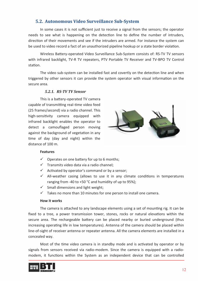
5.2.1. RS-TV TV Sensor
This is a battery-operated TV camera capable of transmitting real-time video feed (25 frames/second) via a radio channel. This high-sensitivity camera equipped with infrared backlight enables the operator to detect a camouflaged person moving against the background of vegetation in any time of day (day and night) within the distance of 100 m.
Features
Operates on one battery for up to 6 months; Transmits video data via a radio channel; Activated by operator’s command or by a sensor; All-weather casing (allows to use it in any climate conditions in temperatures
ranging from -40 to +50 °С and humidity of up to 95%); Small dimensions and light weight; Takes no more than 10 minutes for one person to install one camera.
How it works
The camera is attached to any landscape elements using a set of mounting rig. It can be fixed to a tree, a power transmission tower, stones, rocks or natural elevations within the secure area. The rechargeable battery can be placed nearby or buried underground (thus increasing operating life in low temperatures). Antenna of the camera should be placed within line-of-sight of receiver antenna or repeater antenna. All the camera elements are installed in a concealed way.
Most of the time video camera is in standby mode and is activated by operator or by signals from sensors received via radio-modem. Since the camera is equipped with a radio-modem, it functions within the System as an independent device that can be controlled

13
individually. It’s possible to set which radio sensors will activate the camera and for how long it should run when activated.
After the activation signal is received from an inbuilt modem, the camera processor activates the camera and video data channel. The camera uses a 2.4 GHz one-way channel. The camera starts transmitting video data for a set period of time and then goes into “standby mode”.
Parameters
Parameter Value Detection range (distance, which allows to establish fact of pedestrian presence in monitored area, count number of people or determine position of a raised hand)
min. 100 m
Identification range (distance, which allows to identify pedestrian personality based on his/her appearance)
min. 20 m
TV camera observation angle: horizontally vertically
20.0° 12.5°
Power supply by external battery with voltage 12 V Time of continuous operation without enabling searchlight min. 12 h Time of continuous operation when enabling searchlight min. 6 h Continuous operation time in standby mode min. 6 months Sensor type black and white, CCD Sensor diagonal, inch 0.5 Time between failures 80 000 h Radio channel frequency 433.2−434.6 MHz Radio channel type two-way digital radio channel Video channel frequency 2.414−2.468 GHz Communication range from 0.5 to 3 km IP rating IP67 Operating temperature range from -40 °C to +50 °C Weight:
TV camera TV transmitter
max. 1.0 kg max. 0.7 kg
Dimensions (length×width×height) (excluding projecting parts):
TV camera TV transmitter
170×130×60 mm 140×90×55 mm
5.2.2. RS-TP Thermal Imager
RS-TP Thermal Imager is a battery operated thermal camera that detects body heat of intruders through smoke, darkness, or heat-permeable barriers. The image of the area within the detection zone of RS-TP is transmitted to receiving equipment via radio channel.

14
Features
Operates on one battery for up to 6 months; Transmits video data via a radio channel; Activated by operator’s command or by a sensor; All-weather casing (allows to use it in any climate conditions in temperatures
ranging from -40 to +50 °C and humidity of up to 95%); Small dimensions and light weight; Takes no more than 10 minutes for one person to install one camera.
How it works
The camera is attached to any landscape elements using a set of mounting rig. It can be fixed to a tree, a power transmission tower, stones, rocks or natural elevations within the secure area. The rechargeable battery can be placed nearby or buried underground (thus increasing operating life in low temperatures). Antenna of the camera should be placed within line-of-sight of receiver antenna or repeater antenna. All the camera elements are installed in a concealed way.
Most of the time video camera is in standby mode and is activated by operator or by signals from sensors received via radio-modem. Since the camera is equipped with a radio-modem, it functions within the System as an independent device that can be controlled individually. It’s possible to set which radio sensors will activate the camera and for how long it should run when activated.
After the activation signal is received from an inbuilt modem, the camera processor activates the camera and video data channel. The camera uses a 2.4 GHz one-way channel. The camera starts transmitting video data for a set period of time and then goes into “standby mode”.
Parameters
Parameter Value Detection range for pedestrian, group of people, vehicle, animal
min. 200 m
Observation angle: horizontally vertically
min. 23.0° min. 17.0°
Continuous operation time min. 12 h Continuous operation time in standby mode min. 6 months Time between failures 80 000 h Power supply by external battery with voltage 12 V Radio channel frequency 433.2−434.6 MHz Radio channel type two-way digital radio channel Video channel frequency 2.414−2.468 GHz Communication range between RS-TP and video receiver depending on the type of antenna
from 0.5 to 3 km
IP rating IP67 Operating temperature range from -40 °C to +50 °C

15
Weight max. 2.6 kg Dimensions (length×width×height) (excluding projecting parts):
thermal imaging camera thermal imaging transmitter
220×89×73 mm 140×90×55 mm
5.2.3. PTV Portable TV Receiver
The PTV Portable TV Receiver is a component part of the video control sub-system and is designated to receive the video signal via a radio channel from RS-TV TV cameras and generating the image on a monitor.
The PTV Portable TV Receiver is designed to receive video in the process of its deployment in the terrain, when deployment of the operator’s console is impossible. For example, when performing special tasks or monitoring surveillance targets (paths, pipeline tapping, etc.).
How it works
The PTV Portable TV Receiver is adapted to operation under field conditions and serves for checking and adjusting the video control sub-system during its deployment on the terrain.
Parameters
Parameter Value Rated voltage of built-in rechargeable battery 3.7 V Continuous operation time (under normal climatic conditions)
up to 2.2 h
Video signal receiving range in conditions of direct visibility depending on the type of antenna
from 0.1 to 5 km
Time between failures 80 000 h IP rating IP53 Operating temperature range from -10 °C to +50 °C Weight max. 0.9 kg Dimensions (length×width×height) (excluding antenna)
220×110×50 mm

16
5.3. Controlling and Receiving Devices Used for receiving and displaying alarm and service information from the system’s
devices.
The PORT Operator’s Console is a portable (notebook) or desktop computer with the Windows operating system and specialized Mapping System software. It may be the computer supplied as part of the system or the one already available to you.
The “GIS SENTRY RB” Command and Control software displays the location and operational condition of sensors and other elements on an electronic map or area plan, and enables the operator to control the network.
5.3.1. MPO Portable Operator’s Console
The MPO Portable Operator’s Console is a laptop computer integrated into a rugged carrying case with network communication devices and uninterruptable power supply.
Features
Designed to display installed sensors on an electronic area map and control their operational parameters;
Monitoring operational integrity and battery condition of installed sensors every minute;
Representing alarms by sound and light signals;
Logging alarm messages in text and graphic form and recording video clips from video surveillance sub-system;
Exchange of text messages between KOPR Handheld Control Receivers within radio transmission range.
Parameters
Parameter Value
Unattended continuous operation time from fully charged built-in battery
min. 24 hours
Radio channel frequency 433.2−434.6 MHz Radio channel type two-way digital radio channel Video channel frequency 2.414−2.468 GHz IP rating (in the lid is closed and locked) IP65 Operating temperature range from -40 °C to +50 °C Weight max. 12 kg Dimensions (length×width×height): in travelling position in operating position
560×390×240 mm 650×465×468 mm

17
5.3.2. “GIS SENTRY RB” Command and Control Software
"GIS SENTRY RB" Command and Control Software (hereinafter "GIS SENTRY RB") is a Command and Control Software for Wireless Intrusion Detection System.
A command and control software is designed to process messages sent by network technical devices, display technical devices status, control technical devices operating modes and notify the Operator (by sound signals, text messages, changes in color and configuration of displayed icons, video image) of alarm situations within the monitored area.
Picture 3. “GIS SENTRY RB” interface displaying RS-U Multi-Sensors deployed over a pipeline.
Coordinates of sensors are referenced to a graphical layout or map of monitored area to provide visualization of alarm information and perform analysis of alarm situation.
The "GIS SENTRY RB” software provides operation of a PC (a part of the Operator’s Console delivery set) within the data exchange network via radio channel by connecting a transceiver (a RS-U Multi-Sensor or a TV-BPO TV Control Station) to a PC.
Ethernet or RS232 interfaces can be used for transceiver connection. A MOXA server can be used to establish an interface between Ethernet and RS232.
The "GIS SENTRY RB" software controls operation of sensors, control receivers and other devices operating in data-exchange network via synchronous protocol. The software is able to operate with unlimited number of networks, which is why it is possible to provide monitoring over several areas using only one MPO Portable Operator's Console.
Features
Designed to display installed sensors on an electronic area map and control their operational parameters.
Monitoring operational integrity and battery condition of installed sensors.

18
Representing alarms by sound and light signals. Logging alarm messages in text and graphic form and recording video clips from
video surveillance system. Exchange of text messages between KOPR Handheld Control Receivers within radio
transmission range.
5.3.3. KOPR Control Receiver
It is used to receive, display and store alarm signals of detection devices, locate sensors and monitor their status, as well as to monitor and control the radio network. It is equipped with a digital compass and a GPS-receiver, and is capable of sending and receiving short text messages within the network.
KOPR Control Receiver is used for setting smaller temporary perimeters (up to 10 devices). KOPR can work as network node or as network controller.
KOPR Control Receiver is required for installation and start-up of the system’s devices and it can serve as a receiving and controlling device in field conditions.
Features
Receives alarm signals from one radio network (including up to 40 devices); Allows monitoring every network element; Allows controlling radio sensors’ mode; Allows measuring seismic noise level and changing RS-U sensitivity level when it
works as a seismic detection device; Keeps in its memory GPS coordinates of devices’ locations; Allows locating devices on site (using inbuilt GPS receiver and a digital compass).
Parameters
Parameter Value Rated voltage of built-in rechargeable battery 3.7 V Continuous operation time (without enabling GPS-receiver and electronic compass)
min. 72 h
Radio channel frequency 433.2−434.6 MHz Radio channel type two-way digital radio channel Communication range in conditions of direct visibility depending on the type of antenna
min. 500 m
Time between failures 80 000 h IP rating IP53 Operating temperature range from -10 °C to +50 °C Weight: max. 0.65 kg Dimensions (length×width×height) (excluding antenna)
210×95×45 mm

19
5.4. Other Equipment 5.4.1. TV-BPO TV Control Station
TV-BPO Control Station is designed to receive video signal via radio channel, convert it into a digital format and transmit it to a PC.
TV-BPO Control Station consists of two units connected by means of MBK Interconnecting Cable. BTS Network TV Unit is a desktop device installed next to a PC. BVA External Antenna Unit is a sealed device installed next to 2.4 GHz Base Circular Antenna (ABK-2.4) by means of AMU Antenna Mounting Mast.
Parameters
Parameter Value Power supply by external battery with voltage 12 V Radio channel frequency 433.2−434.6 MHz Radio channel type two-way digital radio channel Video channel frequency 2.414−2.468 GHz IP rating:
BTS Network TV Unit BVA External Antenna Unit
IP54 IP67
Operating temperature range: BTS Network TV Unit BVA External Antenna Unit
from 0 °C to +40 °C
from -40 °C to +50 °C Weight:
BTS Network TV Unit BVA External Antenna Unit
max. 1.15 kg max. 0.55 kg
Dimensions (length×width×height): BTS Network TV Unit BVA External Antenna Unit
250×215×80 mm
130×90×55 mm
5.4.2. TV-R TV Repeater
TV-R TV Repeater is a small-sized device powered by external battery designed to retransmit video signal via radio channel.
TV-R TV Repeater operating modes
standby mode – TV-R is on-line and is ready for video signal receipt and retransmission;
active mode – TV-R receives and retransmits video signal via high-frequency radio channel at receiving triggering command either from Operator's request or from sensors.
BVA External Antenna Unit
BTS Network TV Unit

20
Parameters
Parameter Value Power supply by external battery with voltage 12 V Communication range of radio channel for receipt and retransmission of video signal in conditions of direct visibility irrespective of antenna type
from 0.7 to 3 km
Radio channel frequency from 433.2 to 434.6 MHz Radio channel type two-way digital radio channel Continuous operation time in active mode min. 10 h Continuous operation time in standby mode min. 6 months Transmission frequency from 2.414 to 2.468 GHz IP rating IP67 Operating temperature range from -40 °C to +50 °C Weight max. 2.4 kg Dimensions (length×width×height) (excluding projecting parts)
245×160×70 mm
5.4.3. MR Trunk Repeater
MR Trunk Repeater is designed to provide connection with low-level network devices and to repeat messages to high-level network devices.
MR Trunk Repeater functions are as follows:
automatic organization of high-level network; receipt and transmission of alarm data from
low-level network devices to Operator's workstation; transmission of Operator control commands to low-level networks.
Parameters
Parameter Value Power supply by external battery with voltage 10 V Duration of unattended operation when powered by VIP-1013 External Battery
min. 1 year
Radio channel frequency 433.2−434.6 MHz Radio channel type two-way digital radio channel Range of communication between two MR Trunk Repeaters in conditions of direct visibility when using 433 MHz Cable Antenna
min. 5 km
Time between failures 80 000 h IP rating IP68 Operating temperature range from -40 °C to +50 °C Weight max. 0.5 kg Dimensions (length×width×height) (excluding projecting parts)
140×60×40 mm

22
5.4.6. VIP-1013 External Battery
VIP-1013 External Battery is a lithium battery used for supplying DC power to network devices.
Parameters
5.4.7. VIP-1272 External Battery
VIP-1272 External Battery is a rechargeable lead-acid battery used for supplying DC power to network devices.
Parameters
Parameter Value Internal battery type LSH 20 Output voltage from 10.8 to 11.6 V Voltage at load current of 0.3 A min. 10 V Capacity at discharge current of 0.015 A min.12 Ah Operating temperature range from -40 °C to +50 °C Weight max. 0.8 kg Dimensions (length×width×height) (excluding projecting parts)
126×76×48 mm
Cable length 650 mm
Parameter Value Output voltage from 12.5 to 13.8 V Voltage at load current of 1 A min. 12 V Capacity at discharge current of 1 A min. 5 A·h Average lifetime min. 200 charge-discharge
cycles Operating temperature range from -40 °C to +50 °C Weight 3.3 kg Dimensions (length×width×height) (excluding projecting parts)
175×90×150 mm

23
5.4.8. ASh-433 433 MHz Whip Antenna
ASh-433 433 MHz Whip Antenna is designed to provide wireless data exchange between sensors. The ASh-433 is a demountable, camouflageable antenna with a cruciform-shaped antenna counterpoise. It is a standard antenna to be used with RS-U sensor.
Parameters
Radiation pattern
in the vertical plane when antenna is installed on:
ground surface
metal surface
when antenna is installed above ground, SWR = 1.3, maximum gain of 5 dBi
*communication range is specified for conditions of direct visibility and normal magnetic environment, range of communication can decrease if antenna is covered with snow of more than 10 cm.
Parameter Value Bandwidth (SWR=2.0) 15 MHz Frequency range 410 – 450 MHz Horizontal radiation pattern circular pattern Antenna gain 4 dBi Connector TL4521-58 (TNC 7406A) Range of communication between two sensors when using ASh-433*
up to 1.5 km
Operating temperature range from minus 40 °C to plus 50 °C IP rating IP68 Weight max. 0.25 kg Dimensions (excluding cable)
Height Diagonal of the basement
500 mm 350 mm

24
5.4.9. AShV-433 433 MHz Long Whip Antenna
AShV-433 433 MHz Long Whip Antenna is designed to provide wireless data exchange between sensors deployed in area without tall trees, where a long communication distance is required. The AShV-433 is a demountable antenna with an inductance coil which can be easily camouflaged.
Parameters
The AShV-433 can be installed on any kind of surface or above ground. The antenna can be used without the basement (the basement is detachable).
Radiation pattern
in the vertical plane when installing the antenna on ground surface (SWR = 1.5)
when installing antenna on metal surface (SWR = 1.0)
*communication range is specified for conditions of direct visibility and normal magnetic environment .
Parameter Value Bandwidth (SWR=1.5) 25 MHz Frequency range 410 – 450 MHz Horizontal radiation pattern circular pattern Antenna gain 4 dBi Connector TL4521-58 (TNC 7406A) Range of communication between two sensors when using AShV-433*
up to 5 km
Operating temperature range from minus 40 °C to plus 50 °C IP rating IP68 Weight max. 0.3 kg Dimensions (excluding cable)
Height Diagonal of the basement
800 mm 350 mm

25
5.4.10. KBV-433 433 MHz Cable Antenna
KBV-433 433 MHz Cable Antenna is designed to provide wireless data exchange between sensors and used along with the sensors which are operated in repeaters mode. The KBV-433 can be easily camouflaged. The KBV-433 is installed on a tree or a support. Optimum altitude of the antenna installation is from 2.5 to 3 m.
Parameters
Radiation pattern
In the vertical plane when lifting the antenna above the ground
*communication range is specified for conditions of direct visibility and normal magnetic environment.
Parameter Value Bandwidth (SWR=1.5) 25 MHz Frequency range 410 – 450 MHz Horizontal radiation pattern circular pattern Antenna gain 5 dBi Connector TL4521-58 (TNC 7406A) Range of communication between two sensors when using KBV-433*
up to 10 km
Operating temperature range from minus 40 °C to plus 50 °C IP rating IP68 Weight max. 0.15 kg Dimensions (excluding cable)
Height Width
700 mm
35 mm

26
5.4.11. AMSh-433 433 MHz Magnetic Base Whip Antenna
The AMSh-433 433 MHz Magnetic Base Whip Antenna is designed to provide wireless data exchange between sensors. The AMSh-433 is a two-section whip (1/4 + 5/8 wave) on a magnetic basement. The AMSh-433 is installed on a metallic surface (e.g. car roof).
Parameters
Radiation pattern
in the vertical plane when antenna is installed on metal surface
Dependence of SWR on frequency
SWR < 1.5 within frequency interval from 427 to 440 MHz
*communication range is specified for conditions of direct visibility and normal magnetic environment.
Parameter Value Bandwidth (SWR=2.0) 20 MHz Frequency range 410 – 450 MHz Horizontal radiation pattern circular pattern Antenna gain 5 dBi Connector TL4521-58 (TNC 7406A) Range of communication between two sensors when AMSh-433 and ASh-433 are used*
up to 4 km
Operating temperature range from minus 40 °C to plus 50 °C IP rating IP68 Weight max. 1.1 kg Dimensions (excluding cable)
Height Diagonal of the basement (2 variants of execution)
755 mm
80 mm or 125 mm

27
5.4.12. BSL Liner Interface Box
BSL Linear Interface Box consists of three units: BUR Relay Control Unit and BKR Switching Relay Unit (from 1 up to 5 units). BSL is designed to receive data from sensors and to transmit alarm data to remote Control Station via cable communication lines.
BSL versions:
8-way BSL-08: BUR+BKR (1 pc)
16-way BSL-16: BUR+BKR (2 pcs)
24-way BSL-24: BUR+BKR (3 pcs)
32-way BSL-32: BUR+BKR (4 pcs)
40-way BSL-40: BUR+BKR (5 pcs)
Parameters
IMPORTANT!All the above components constitute the main part of the Radiobarrier System. The
system may also include other minor components, such as connecting cables, other antennas, supplementary software, packaging, spare parts, etc. These minor components may be supplied with the system depending on the requirements.
The manufacturer reserves the right to modify any of the components of the system and add new components, provided these modifications and additions improve and enhance the system’s performance.
Parameter Value Communication range in conditions of direct visibility depending on the type of antenna
from 0.5 to 5 km
Number of sensors assigned to one relay unit max.16 Radio channel frequency 433.2−434.6 MHz Radio channel type two-way digital radio channel IP rating IP53 Operating temperature range from -40 °C to +50 °C Weight:
BUR Relay Control Unit BKR Switching Relay Unit
max. 0.55 kg
max. 0.5 kg Dimensions (length×width×height):
BUR Relay Control Unit BKR Switching Relay Unit
126×73×68 mm 131×84×52 mm

28
6. Conclusion
SENTRY RB System is a unique and cost efficient solution for surveillance of extended perimeters and remote areas. It's truly mobile and autonomous architecture makes it the best surveillance solution for use in mountainous areas and areas with no access to power, or communication infrastructure. Simplicity of installation and operation allows avoiding design stage in most projects, saving money and time.


