SEPARATION OFCQ AND H2 MIXTURES USING REACTIVE ION EXCHANGE MEMBRANES by J. Douglas Way and R. Lane Hapke SRI International Chemical Engineering Laboratory Menlo Park, CA 94025. Introduction Currently, the most widely used method for producing hydrogen is steam reforming of methane. The volatility in the price of natural gas has created increased interest in finding alternative feedstocks for the manufacture of hydrogen. Thus, it is appropriate at this time to conduct research which has the best opportunities for- reducing H2 production costs from Coal gasification. Bartis and Marks (1984) have identified low energy separation processes such as membranes as a key research opportunity in reducing capital and operating costs and hence the H2 production costs. They state that technical improvements in gas separation could lead to production cost reductions of 15 to 20 percent. Figure 1 is a block flowsheet of a process to produce hydrogen from synthesis gas. There are two points in the process where gas separation processes take place. Acid gases must be removed from the gas stream after gasification and prior to the shift reaction. This separation step prevents sulfur poisoning of the shift catalysts and maximizes hydrogen production from the shift reaction. The second gas separation occurs after the shift reaction. C02 must be removed from the product stream to produce high purity Hp. Membrane Separations The use of membrane separations for the gas separation processes described above is an area deserving special attention because of its great potential for low capital cost and energy efficiency (Matson et al., 1983). A membrane process could theoretically separate a binary mixture reversibly, and therefore consume only the minimum work to accomplish the separation. The implicit simplicity and energy 283
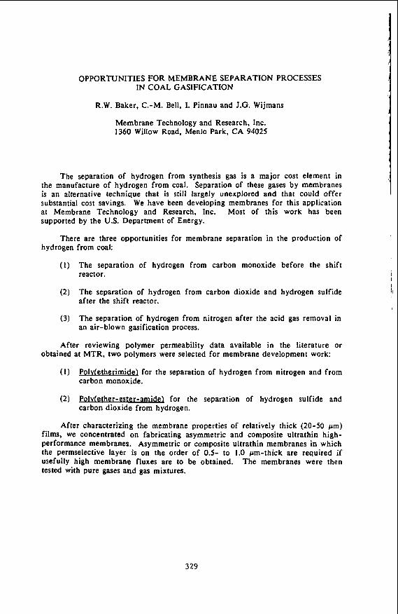
Transcript
SEPARATION OFCQ AND H2 MIXTURES USING REACTIVE ION EXCHANGE MEMBRANES
by
J. Douglas Way and R. Lane Hapke SRI International
Chemical Engineering Laboratory Menlo Park, CA 94025.
Introduct ion
Currently, the most widely used method for producing hydrogen is steam
reforming of methane. The volatility in the price of natural gas has created increased
interest in finding alternative feedstocks for the manufacture of hydrogen. Thus, it is
appropriate at this time to conduct research which has the best opportunities for-
reducing H2 production costs from Coal gasification.
Bartis and Marks (1984) have identified low energy separation processes such
as membranes as a key research opportunity in reducing capital and operating costs and
hence the H2 production costs. They state that technical improvements in gas separation
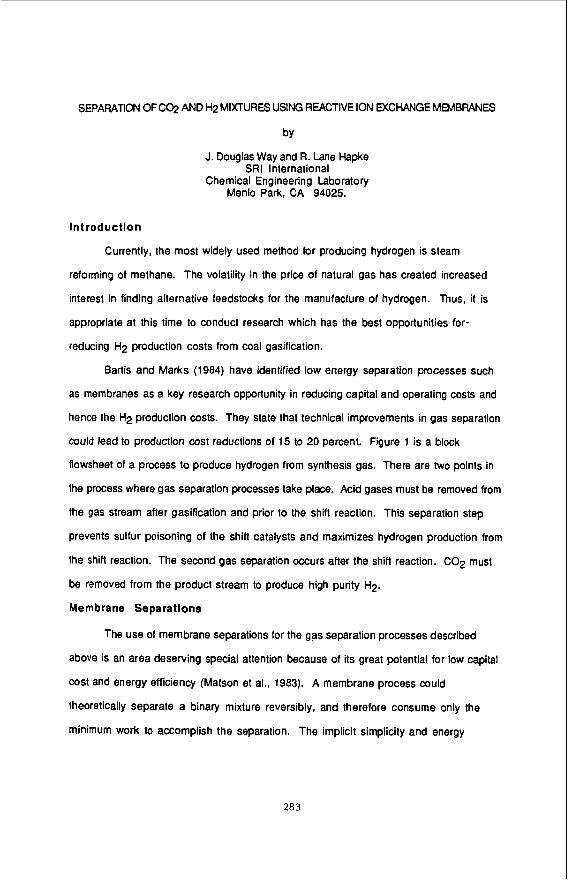
could lead to production cost reductions of 15 to 20 percent. Figure 1 is a block
flowsheet of a process to produce hydrogen from synthesis gas. There are two points in
the process where gas separation processes take place. Acid gases must be removed from
the gas stream after gasification and prior to the shift reaction. This separation step
prevents sulfur poisoning of the shift catalysts and maximizes hydrogen production from
the shift reaction. The second gas separation occurs after the shift reaction. C02 must
be removed from the product stream to produce high purity Hp.
Membrane Separations
The use of membrane separations for the gas separation processes described
above is an area deserving special attention because of its great potential for low capital
cost and energy efficiency (Matson et al., 1983). A membrane process could
theoretically separate a binary mixture reversibly, and therefore consume only the
minimum work to accomplish the separation. The implicit simplicity and energy
283
High Pressure Steam Solids H2S.C 0 2
Separation Process
Solids Cooling Removal Gasification
cp2
Shift Reaction Process 1 or 2 stage
RA-rn-360583-34
FIGURE 1 BLOCK ROW DIAGRAM OF HYDRoGp( PRODUCTDN FROM SYFrmESlS GAS
284
efficiency of membrane processes have stimulated basic and applied research for many
years.
The selective removal of C02 from mixtures of Hp, CO, and other gasification
products using membranes depends on the appropriate choice of the membrane material.
Many glassy polymers commonly used in commercial gas separation membranes are
more permeable to H2 than Cop. The ideal separation factor, a(HplC02) for
commercial asymmetric cellulose ester membranes is 2.2 (W, R. Grace, 1986) while
the value for the polydimethylsiloxanelpolysulfone composite membranes is 2.3 (Henis
and Tripodi.1980). Due to the large diffusivity of Hp in typical glassy polymer
materials the permeability coefficient (product of the diffusivity and solubility) of Hp
is greater than that of Cop. While diffusivity controls the selectivity in glassy
polymers, in rubbery polymers such as polydimethylsiloxanes (PDMS) or PDMS
copolymers the solubility of penetrant gases controls the selectivity. In this case, the
selectivity of the rubbery polymer membranes is reversed, and the membranes are
more permeable to Cop than to Hp. The ideal separation factors (C02lHp) are 4.9 and
4.6 for PDMS and PDMSlpolycarbonate copolymers, respectively (Robb, 1968; General
Electric, 1982). A separation factor of 6.4 was measured using a commercial GE PDMS
membrane with a 50150 mole % C02lHp feed gas mixture at ambient conditions. The
measured C02 permeability was 2310 Barrer (1 Barrer=10-10
cm3(STP)cmlcm2~s~cm Hg) which is within 7% of the pure component value (General
Electric, 1982). However, the H2 permeability was 359 Barrer, only 70% of the pure
component value. This observation could be explained if the H p solubility, and therefore
the permeability. during the mixture experiment is lower than the pure component
value due to the presence of Cop in the membrane.
Facilltated Transport Membranes
Liquids and solvent swollen ionomer membranes can also be used as membrane
materials (Ward and Robb, 1968; LeBlanc et al., 1980; Way et at., 1987).
285
Incorporation of a complexation agent in these membranes can enhance the flux of a
reactive species through a process known as facilitated transport. Way et al. (1987)
have demonstrated facilitated transport of COP through water-saturated
perfluorosulfonic acid ion exchange membranes (IEMs) containing monopositive
ethylene diamine as a counterion.
Ion exchange membranes containing EDA were prepared using the method of Way
et al. (1 987) using nominal 30 &m NE-1 11 perfluorosulfonic acid membranes. The
experimental NE-1 11 membranes have an equivalent molecular weight of 1 100 gleq
and are not available commercially. Preliminary transport measurements were
performed at 25 "C and 1 atm to determine the COP and Hp permeabilities of the NE-1 11
IEMs. The pure component COP permeability was 145 Barrer, in good agreement with
the value of 146 Barrer previously reported by Noble et al. (1988). The H2
permeability was 21.2 Barrer, corresponding to an ideal separation factor of 6.84 for
the NE-1 11 IEM. The ideal separation factor for water, calculated by determining the
ratio of permeability coefficients, is 17.2 at 25 "C and 1 atm (Kohl and Riesenfeld,
1985; Cussler, 1984). A possible explanation of the lower separation factor for the
water-swollen IEM is that Hp may diffuse through both the water containing cluster-
channel network phase of the IEM (Gierke, 1977) and the fluorocarbon polymer phase.
Further experiments will be performed to determine the permeability and separation
factor for mixtures of C02 and Hp using water as a solvent.
Selectivity improvements may be obtained by preparing facilitated transport
IEMs using polar organic solvents such as propylene carbonate which are used
commercially in physical absorption processes for removing C02 from gas mixtures.
Propylene carbonate has the property that COP is 121 times more soluble than H2 at
ambient conditions (Kohl and Riesenfeld, 1985). Assuming that the ratio of the
diffusion coefficients (C02/H2) in propylene carbonate is the same as water, an ideal
separation factor (C02/H2) of approximately 50 can be calculated.
206
Summary
Liquids and rubbery polymers are good candidate membrane materials for the
separation of COP from mixtures with H2 because the solubility selectivity controls the
separation that can be obtained. Facilitated transport IEMs containing monopositive
ethylene diamine counterions have been shown to be selectively permeable to C02 over
H2. Transport measurements will be conducted to determine the influence of feed gas
mixture composition, pressure, temperature, and solvent on the C02 and Hp
permeabilities and separation factor.
Ac knowledgernent
The authors would like to ackowledge the support of the Dept. of Energy
Morgantown Energy Technology Center for this work under subcontract
NB773000707471 to DOE Contract No. DE-AI21 -86MC23120, with special thanks to
Ms. Lisa A. Jarr. We would also like to acknowledge Dr. Louis L. Burton of E. 1. duPont de
Nemours 8 Co., Inc., for supplying developmental forms of perfluorinated ion exchange
membranes.
References
Bartis , J. T.. and L. S. Marks, "Technical Evaluation and Systems Analysis of Hydrogen Production from Coal," Final Report for DOE Contract No. DE-AP21-84MC02159 (August, 1984).
Cussler, E. L., Diffusion: Mass Transfer in Fluid Systems, Cambridge University Press, Cambridge (1984).
General Electric Membrane Products Operation, General Electric Permselective Membranes Product Literature, 1982.
Gierke. T. D., "Ionic Clustering in Nafion Perfluorosulfonic Acid Membranes and Its Relationship to Hydroxyl Rejection and Chlor-Alkali Current Efficiency," procZ
Henis, J. M. S., and M. K. Tripodi. U. S. Patent 4,230,463 (1980).
Kohl, A. L., and F. C. Riesenfeld, Gas Purification, 4th Edition, Gulf Publishing Co., Houston (1 985).
I Soci-, Atlanta, GA,1977.
28 7
I ,, LeBlanc, 0. H., Ward, W. J., Matson, S. L., and S. G. Kimura, "Facilitated Transport in L '
I' Ion Exchange Membranes," J. Mem. Sci., 6, 339-343(1980).
Matson, S. L., Lopez, J. and J. A. Quinn. "Separation of Gases With Synthetic Membranes," Chem. Eng. Sci., 38, 503-524(1983).
Noble, R. D., Pellegrino, J. J., Grosgogeat. E., Sperry, D., and J. 0. Way, "COP Separation Using Facilitated Transport Ion Exchange Membranes," Sep. Sci. Tech., accepted for publication, 1988.
I
I I
Robb, W. L., "Thin Silicone Membranes-Their Permeation Properties and Some Applications," Ann. N. Y. Acad. Sci. 146, 119-137(1968).
Ward, W. J., W. L. Robb, "Carbon Dioxide-Oxygen Separation: Facilitated Transport of Carbon Dioxide Across a Liquid Film,' Science, 156, 1481 (1 967).
Way, J. D.. Noble, R. D., Flynn, T. M., and E. 0. Sioan. "Liquid Membrane Transport: A SUWey," J. Mem. Sci., 12, 239-259(1982).
i
I
288
SEPARATIONS OF OLEFINS AND HETEROCYCLIC ORGANIC COMPOUNDS
BASED ON REVERSIBLE COMPLEXATION REACTIONS.
Carl A. Koval,' Steven Drew,' Terry Spontarelli,' Richard D. Nobl; Departments
of Chemistry and Biochemistry'and of Chemical Engineering University of Colorado,
Boulder, CO 80309
While numerous biological processes utilize membranes that contain
transporting agents (carriers) to separate molecular and ionic permeates, the
potential of synthetic membranes for separations in commercial processes has not
been fully realized. In principal, the phenomenon of facilitated transport (FT) in
membranes, which relies on the reversible formation of a permeate:carrier complex,
can provide selective and efficient separations. Recently, membranes and thin films
derived from ion exchange materials have received considerable attention with
respect to their structural, physical and chemical properties. We report the facilitated
transport of 1-hexene and 1,5hexadiene between two decane phases separated by
thin, hydrated membranes (ca. 25 pm). The flux of olefin across the membranes is
enhanced by factors of several hundred when silver ions are exchanged for sodium
ions.
Flux measurements were made using a two compartment cell arranged
vertically and separated by the membrane which was held in place with O-rings and a
clamp. The surface area of the membranes exposed to the solution was 1.8 cm2.
Both compartments of the cell contained decane (20 mL) that had been saturated
with water and were mechanically stirred to provide efficient mass transport to and
from the membrane. The lower compartment contained either 1-hexene or 1,5-
hexadiene (0.1 M). After the cell was assembled, aliquots (1 pL) of the solution were
removed periodically with a syringe from the upper compartment and injected into a
289
gas chromatograph. The GC response for the olefins was monitored continuously by
the injection of standards.
For membranes in the Na+-form, the flux of olefin across the membrane was
quite low, but stable for over two days. Transport rates were much higher for the
membranes in the Ag+-form. In both cases, plots of concentration of olefin in the
upper compartment
the membrane which can be readily calculated from the Slopes: JNa+,hexene = 2.4
time were linear. This indicates a constant flux of olefin across
JAg+,hexene = 1.1 X JNa+,hexadiene = 4.0 X and
JAg+,hexadiene = 1.8 X (all J'S in mol Cm-2 SeC-l).
We attribute the enhanced olefin flux for the Ag+-form of the membrane to the
reversible complexation of the olefins with silver ion:
Ag+ + olefin = Ag(olefin)+.
Formation constants for these complexes have been reported for 1-hexene (K = 860
M-1) and 1,5-hexadiene (K = 1850 M-1) in 1 M aqueous AgN03. Assuming that the
enhanced fluxes are due to facilitated transport associated with the mobility of the
Ag(olefin)+ complex, facilitation factors, F, can be calculated as the ratio of the olefin
flux for the Ag+-form to the flux for the Na+-form. From the fluxes calculated above,
Fhexene = 460 and Fhexadiene = 450.
Synthetic fuels derived from coal liquids, tar sands or oil shale contain a wide
variety of nonvolatile chemical compounds containing nitrogen and sulfur. Many of
these compounds display mutagenic or carcinogenic activity. Therefore, these
classes of compounds are undesirable pollutants which must be removed from fuels
and other related hydrocarbon products.
We are exploring a novel process for the selective removal of organic nitrogen
and sulfur compounds (R-N and R-S) from hydrocarbon phases. The process is based
on electrochemically modulated chemical complexation. The complexing agents are
290
water-soluble derivatives of Fe metalloporphyrins. A porphyrin (P) is a tetradentate
macrocyclic ligand. Metalloporphyrins have numerous biological functions including
the transport of oxygen. The metal ions in metalloporphyrins bind other molecules
(ligands) in addition to the porphyrin itself. These bonds are perpendicular to the
plane of the porphyrin so the bound molecules are referred to as axial ligands.
Reversible reactions between metalloporphyrins and organic compounds containing
nitrogen and sulfur are the basis for this separation process. In general, these
complexation reactions have greater equilibrium constants when the metals are in
the +2 oxidation state as opposed to the +3 state. Interconversion of the Fe(lll) and
Fe(ll) states in metalloporphyrins is a kinetically facile process at metal electrodes.
By applying relatively mild potentials, we can achieve the cyclical process:
cathode: Fe(1ll)P + e - Fe(ll)P
Fe(ll)P + R-N or R-S - Fe(ll)P(RN or RS)1 or 2
Fe(ll)P(RN or RS)1 or 2 - Fe(lll)P + e- + R-N or R-S. anode:
The reactions described above can be incorporated into a staged
electrochemical separation process. Results for the removal of isoquinoline and
pentamethyene sulfide from iso-octane and the subsequent concentration of these
compounds is a second (waste) hydrocarbon phase will be presented.
29 1
REMOVAL OF HYDROGEN CHLORIDE FROM HIGH TEMPERATURE COAL GASES
Gopala N. Krishnan, Bernard J. Wood, and Gilbert T. Tong
SRI International 333 Ravenswood avenue, Menlo Park, CA 94025
Vijendra P. Kothari
U.S. Department of Energy, Morgantown Energy Technology Center 3600 Collins Ferry Road, Morgantown, WV 26505
Introduction The chlorine content of U . S . coals ranges from 0.01 to 0 . 5 % ,
and some coals in U.K. contain as high as 1.0% ch1orine.l This element is present in the coal mainly as alkali chlorides, but it also occurs as oxychlorides of calcium and magnesium.2 coal gasification or combustion, these chloride species are converted to HC1 vapor. Concentrations of HC1 vapor in coal gas have been found in the range 1 to 500 ~ p m . ~ The presence of HC1 in the coal gas can lead to corrosion of metallic and ceramic components of the gasifier, attack gas turbine components and to poisoning of molten carbonate fuel cell electrodes.
Energy's lead center for coal gasification and gas stream cleanup technology, has been concerned for some years with the purification of coal-derived gases for a range of applications including gas turbine, fuel-cell, and combined-cycle power generation. Removal of harmful impurities from the coal gas stream at elevated temperatures (>500'C) is necessary for achieving high thermal efficiency in such applications. the tolerance to HC1 level of fuel cells has not been determined accurately, it is typical to specify that fuel cell feedstocks should contain no more than 1 ppm HC1. Similar requirements may be necessary in turbine applications. Currently available processes for removing HC1 vapor operate at relatively low temperatures (T < 3OO0C) and thus they are not suitable for use with hot coal gases (T > 5OOOC). This paper presents the results of a laboratory-scale evaluation conducted at SRI International to determine the effectiveness of naturally occurring minerals and commercially available sorbents to remove HC1 vapor from simulated coal gas streams at temperatures from 550' to 650°C.4
The thermodynamic stability and the volatility of the s o l i d chloride products were the major criteria in selecting the nature of the sorbent. Alkaline earth chlorides, generally, are less volatile than alkali metal chlorides and transition metal
During
Morgantown Energy Technology Center, as the U.S. Department of
Although
292
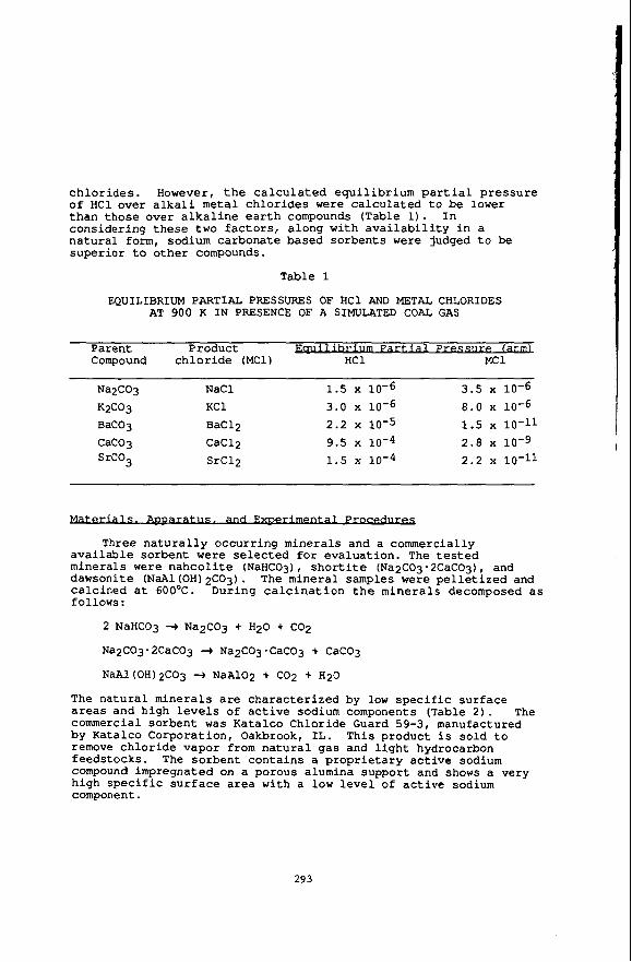
c h l o r i d e s . However, t h e c a l c u l a t e d e q u i l i b r i u m p a r t i a l p r e s s u r e o f H C 1 over a l k a l i metal c h l o r i d e s were c a l c u l a t e d t o be lower than those over a l k a l i n e e a r t h compounds (Table 1) . I n cons ider ing t h e s e two f a c t o r s , a long wi th a v a i l a b i l i t y i n a n a t u r a l form, sodium carbonate based so rben t s were judged t o be supe r io r t o o t h e r compounds.
T a b l e 1
EQUILIBRIUM PARTIAL PRESSURES O F HC1 AND METAL CHLORIDES AT 900 K I N PRESENCE O F A SIMULATED COAL GAS
Parent Product u r e ( a t u Compound c h l o r i d e (MC1) HC1 MC1
Na2C03 NaCl 1 .5 x 3 .5 x 10-6 K2C03 KC1 3 .0 x 8.0 x 10-6 BaC03 BaC12 2.2 10-5 1 .5 x CaC03 CaC12 9.5 10-4 2.8 10-9 SrC03 SrC12 1.5 10-4 2.2 x 10⁻¹¹
Three n a t u r a l l y occur r ing minera ls and a commercially a v a i l a b l e sorbent were s e l e c t e d f o r eva lua t ion . The tested minera ls were n a h c o l i t e (NaHC03) , s h o r t i t e (Na2C03 - 2CaC03), and dawsonite (NaAl(OHlgCO3). The minera l samples w e r e p e l l e t i z e d and ca l c ined a t 60OoC. During c a l c i n a t i o n t h e m i n e r a l s decomposed a s follows:
2 NaHC03 --t Na2C03 + H 2 0 + C02
Na2C03-2CaC03 + Na2C03.CaC03 + CaC03
NaAl(OH)2C03 3 N a A 1 0 2 + C02 + H20
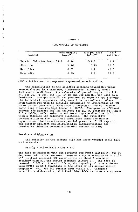
The n a t u r a l mine ra l s a r e cha rac t e r i zed b y low p e c i f i c su r face a r e a s and high l e v e l s of a c t i v e sodium components (Table 2 ) . The commercial so rben t was Katalco Chlor ide Guard 59-3, manufactured by Katalco Corpora t ion , Oakbrook, I L . This product i s s o l d t o remove c h l o r i d e vapor from n a t u r a l gas and l i g h t hydrocarbon f eeds tocks . The so rben t con ta ins a p r o p r i e t a r y a c t i v e sodium compound impregnated on a porous alumina suppor t and shows a very h igh s p e c i f i c s u r f a c e a rea with a low l e v e l of a c t i v e sodium component.
293
/ Table 2
PROPERTIES OF SORBENTS
Bulk d e n s i t y Surface area ASCl Sorbent (9. cm-3 ) (m2.g-1) ( w t % N a l
Katalco Chloride Guard 59-3 0.76 247.0 4.7 S h o r t i t e 1.46 0.25 15.0 Nahcol i te 0.65 1.2 40.3 Dawsonite 0.59 2.3 16.5
IASC = Active sodium component expressed as w t % sodium.
The reactivities o f t h e s e l e c t e d s o r b e n t s toward HC1 vapor were e v a l u a t e d i n a t h i n bed, microreac tor (Figure 1) under i so thermal condi t ions . A s imulated c o a l g a s of composition 22% H2, 34% CO, 7% Cop, 36% H20, 1% H e and 300 ppm HC1 was used as a feedstock. t h e i n d i v i d u a l components us ing mass flow c o n t r o l l e r s . Glass or PTFE t u b i n g w a s used t o minimize adsorp t ion or i n t e r a c t i o n of HC1 vapor on t h e tube w a l l s . Glass w a l l s exposed t o t h e H C l stream c o n t a i n i n g steam was kept hea ted t o 180OC. The gaseous e f f l u e n t leav ing t h e sorbent bed w a s analyzed f o r HC1 by r e a c t i n g it w i t h a 0 . 5 M NaHC03 b u f f e r s o l u t i o n and measuring the d i s s o l v e d [Cl-] with a c h l o r i d e ion selective e l e c t r o d e . The cumulat ive concent ra t ion of t h e [Cl-] w a s c a l c u l a t e d us ing the Nernst equat ion and the ins tan taneous p a r t i a l p r e s s u r e of H C 1 vapor i n t h e reactor e f f l u e n t was c a l c u l a t e d by d i f f e r e n t i a t i n g t h e cumulat ive c h l o r i d e concent ra t ion wi th r e s p e c t t o t i m e .
The g a s mixture w a s p repared by meter ing and b l e n d i n g .
The r e a c t i o n of t h e sorbent wi th HC1 vapor y i e l d e d s o l i d NaCl as t h e product :
Nay203 + HC1+2NaCl + C 0 2 + H20
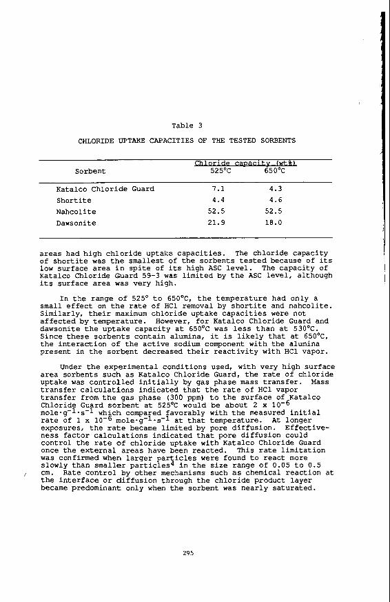
The ra te of r e a c t i o n with t h e sorbents was r a p i d i n i t i a l l y , b u t it decreased wi th t i m e onstream. Even a t a space v e l o c i t y of 5 x l o 4 h-1, i n i t i a l r e s i d u a l H C 1 vapor l e v e l s of about 1 ppm were a t t a i n e d wi th a l l t h e t e s t e d s o r b e n t s (F igure 2 ) . The ra te o f removal of H C 1 and the c h l o r i d e uptake c a p a c i t y of t h e s o r b e n t s were found t o b e a func t ions of t h e l e v e l of i t s a c t i v e sodium component (ASC) and i t s s u r f a c e area (Table 3 ) . Calcined n a h c o l i t e and dawsonite, with t h e i r h igh ASCs and moderate sur face
294
Table 3
CHLORIDE UPTAKE CAPACITIES O F THE TESTED SORBENTS
i t v fwtu Sorbent 525'C 650'C
Katalco Chlor ide Guard 7.1 4.3 Short i t e 4.4 4 . 6
Nahcol it e 52.5 52.5
Dawsonite 21.9 18.0
a r e a s had high c h l o r i d e uptake c a p a c i t i e s . The ch lo r ide capac i ty of s h o r t i t e was the smallest of t h e so rben t s tested because of i t s low su r face area i n s p i t e of i ts high ASC level. The capac i ty of Katalco C h l o r i d e Guard 59-3 was l imi t ed by t h e ASC l e v e l , al though i t s s u r f a c e a r e a was v e r y high.
small e f f e c t on the r a t e of HC1 removal by s h o r t i t e and nahco l i t e . S imi la r ly , t h e i r maximum c h l o r i d e uptake c a p a c i t i e s were not a f f e c t e d by tempera ture . However, f o r Katalco Chloride Guard and dawsonite t h e up take capac i ty a t 650'C was less t h a n a t 530'C. Since t h e s e s o r b e n t s con ta in alumina, it is l i k e l y t h a t a t 65OoC1 the i n t e r a c t i o n o f the a c t i v e sodium component w i t h the alumina present i n t h e so rben t decreased t h e i r r e a c t i v i t y wi th H C 1 vapor.
Under the exper imenta l cond i t ions usedl w i t h very h igh su r face a r e a so rben t s such a s Katalco Chlor ide Guard, t h e r a t e of ch lo r ide uptake was c o n t r o l l e d i n i t i a l l y by gas phase mass t r a n s f e r . Mass t r a n s f e r c a l c u l a t i o n s ind ica t ed t h a t t h e r a t e of HCl vapor t r a n s f e r from t h e gas phase (300 ppm) t o t h e s u r f a c e of Katalco Chlor ide Guard so rben t a t 525OC would be about 2 x mole-g-l.s-l which compared favorably wi th t h e measured i n i t i a l rate of 1 x 10⁻⁶ mole-g-1-s-l a t t h a t temperature. exposuresl t h e r a t e became l i m i t e d by pore d i f f u s i o n . E f fec t ive - nes s f a c t o r c a l c u l a t i o n s i n d i c a t e d t h a t pore d i f f u s i o n could con t ro l t h e r a t e of c h l o r i d e uptake wi th Katalco Chlor ide Guard once t h e e x t e r n a l a r e a s have been r eac t ed . This r a t e l i m i t a t i o n w a s confirmed when l a r g e r p a r t i c l e s w e r e found t o r e a c t more slowly than sma l l e r p a r t i c l e s 4 i n t h e s i z e range of 0.05 t o 0.5
/ cm. Rate c o n t r o l by o t h e r mechanisms such as chemical r e a c t i o n a t t h e i n t e r f a c e o r d i f f u s i o n through t h e c h l o r i d e product l a y e r became predominant only when t h e sorbent was n e a r l y s a t u r a t e d .
I n t h e range o f 525' t o 65OoC1 t h e t empera tu re had only a
A t longer
295
To determine the rate control mechanism with moderate surface area sorbents such as nahcolite, small quantities (0.1 g) of nahcolite were exposed to the gas mixture at a space velocity of 1 X lo5 h-l for various periods of time and the accumulated chloride in the solid was measured. sorbent and the large flow rate, the concentration of HC1 vapor and the composition of the sorbent across the bed could be assumed to be nearly constant. The results of these experiments indicated that the rate of HC1 reaction with nahcolite was limited initially by mass transfer. However, beyond an initial period, chemical reaction at the interface controlled the rate through a major portion of the sorbent active life time as indicated by a linear correlation between the log of the unreacted fraction (1-x) of the sorbent and time (Figure 3 ) . This behavior is to be expected because of the relatively fewer number of micropores in a moderate surface area material in comparison with a high surface area material. Hence, the shift from mass transfer limited rate to chemical reaction limited rate would occur earlier with nahcolite than with Katalco Chloride Guard. After about 80% of the nahcolite sorbent has been reacted, the rate control appears to be limited by diffusion through a chloride product layer as indicated by the non linear behavior in log (1-x) vs. time plot.
Bench-scale experiments were also conducted with these sorbents at the Institute of Gas Technology, Chicago, IL.5 The rate of chloride uptake w a s calculated from the analysis of the chloride content of the spent sorbent as a function of the bed depth. The results of bench-scale experiments were in general agreement with the laboratory-scale experiments although the HC1 removal rate and the chloride capacities were somewhat lower than found in the laboratory-scale experiments. This may be due to the large particles used in the bench-scale study. Impurities such as H2S and trace metals did not affect significantly the rate of HC1 removal or the chloride capacities of the sorbents.
A preliminary economic analysis was performed at SRI to determine the cost of HC1 removal from hot coal gas.4 using Katalco Chloride Guard was estimated to be too high (-$O.OZ/kWh) for use as throwaway sorbent. In contrast, the annual operating cost for the use of nahcolite was estimated to vary from $0.0017 to $0.0031/kWh depending on whether the gasifier is oxygen-blown or air-blown. In this annual operating cost, the capital investment and the capital recovery components are major cost factors whereas the cost of nahcolite sorbent and its chloride capacity have only a small impact.
Because of the small quantity of the
The cost of
The reaction of HC1 vapor with calcined sodium-carbonate based natural minerals and synthetic sorbents is rapid and the HC1 vapor
296
concent ra t ion can be reduced t o about 1 ppm level i n c o a l gas i n t h e temperature range of 525' to 650'C. c o n t r o l l e d i n i t i a l l y by t h e r a t e of mass t r a n s f e r from t h e gas phase t o t h e s u r f a c e of t h e s o r b e n t s . A t later t imes t h e ra te i s c o n t r o l l e d by d i f f u s i o n through micropores i n h igh s u r f a c e area sorbents and by chemical r e a c t i o n i n moderate and low s u r f a c e a r e a sorbents . The presence of H2S and t r a c e metal i m p u r i t i e s d i d not a f f e c t s i g n i f i c a n t l y t h e performance of t h e s o r b e n t s . The c o s t of HC1 removal us ing n a t u r a l l y occurr ing mineral , n a h c o l i t e , i s very l o w .
The rate o f r e a c t i o n i s
Acknowledament
The au thors wish t o acknowledge t h e U . S . Department of Energy, Morgantown Energy Technology Center f o r support of t h i s work under c o n t r a c t N o . DOE-AC21-84MC21167.
References
l . W . H . Ode, "Coal Analysis and Mineral Matter" i n Chemistry of Coal U t i l i z a t i o n , supplementary volume, e d i t e d b y H.H. Lowry, John Wiley and Sons, New York (1963).
2 . T. L. I a p a l u c c i , R. J. Demski, and D. Bienstock, "Chlorine i n Coal Combustion", Reports of I n v e s t i g a t i o n N o . 7260, U . S . Bureau of Mines, (May 1969) .
3 . TRW, "Monitoring Contaminants i n Coal Derived G a s f o r Molten Carbonate Fuel C e l l s " , F i n a l Report t o Argonne Nat iona l Laboratory under c o n t r a c t No. 31-109-38-6108, DOE/METC/82-44 (May 1981) .
4 . G. N. Krishnan, G . T. Tong, B. J. Wood, and N. Korens, "High Temperature Coal Gas Chloride Cleanup f o r Molten Carbonate Fuel C e l l Appl ica t ions" , Report No. DOE/MC21167-2080 (November 1986) .
5 G. L. Anderson and F. 0. Berry, "Chlorine Removal from Hot Coal Gas," Report t o SRI In t e rna t iona l by I n s t i t u t e of Gas Technology under contract No. C-11317 ( A p r i l 1986) . (see Appendix C of Reference 4 ) .
H20 Syringe Pump
Heated S-S Tubing
Peristaltic Liquid Circulating Pump
Reference Electrode Chloride Sensitive
Electrode 0.5 M
NaHC03 Solution
Magnetic Stirring Bar Gas Dispersion Frit
Constant Temperature Bath
JA-7805-1
Figure 1. Schematic diagram of thin bed reactor for studying HCI removal.
298
300
200
100
0
4
8 A A n n b 4 - -
8 +*+++ n 0 A
+ + + A II +
0 0 + A n
0
* * + + CI
0 + A n
0 + n 0 + 0 A Dawsonite
Katalco 0 Nahcolite + Shortite
- 8 +
0 120 240 360 480 600 Tlme (min)
Figure 2. Examples of HCI Breakthrough Curves for Various Sorbents at 525°C Sorbent quantity - Dawsonite = 0.4 g; Nahcolite = 0.2 g
- Katab = 0.23 g; Shortite = 1 .O g
100
10-1
calcined nahcolite
0 100 200 300 400
calcined nahcolite
0 100 200 300 400
Tlme (minutes)
Figure 3 Plot of logarithm of unreacted fraction with time
299
REMOVAL OF H2S FROM COAL-DERIVED GASES by
S. Lynn, R.M. Hix, D.W. Neumann, S.F. Sciamanna, and C.A. Stevens Departmenl o f Chemical Engineering
Universily OJ CaliJornia, Berkeley. C A 94720
In t roductioa
When coal is gasified most of the sulfur is converted to H2S and must be removed before the gas can be used either as a fuel or as synthesis gas. The UCB Sulfur Recovery Process (UCBSRP) is being developed as a general method for removing H2S from gases. The H2S is absorbed in a polyglycol ether, then reacted in the liquid phase with SO2 to form marketable elemental sulfur and water. The process allows high specif ic i ty and flexibility; H2S can be reduced to the part-per-million level or below in the presence of C 0 2 and the other components of gasified coal. The C 0 2 may be left in the original gas stream or it may be co-absorbed and recovered as a separate, sulfur-free product. The process thus has application both to syngas and hydrogen product ion f rom 02-blown gasifiers and to power production using an air-blown gasifier.
Process Configurations
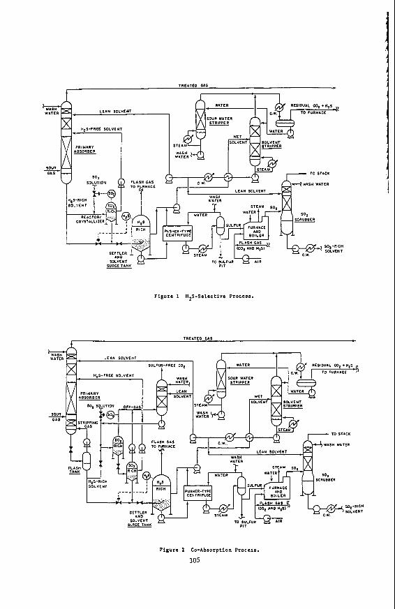
Figure 1 shows a flowsheet for the UCBSRP in a configuration that gives maximum select ivi ty f o r H2S removal. In the pr imary absorber H,2S is removed pr imar i ly by physical absorption. The stream of solvent leaving the absorber is nearly saturated with all of the components of the gas being treated. A water wash at the top of the primary absorber prevents loss of solvent vapor in the treated gas.
Most of the solvent s t ream leaving the pr imary absorber t h e n enters a reactor /crystal l izer tha t operates a t the pressure of the pr imary absorber . A second solvent stream containing SO2 is metered into the same reactor a t a ra te that keeps the SO2 content within the reactor a few percent above stoichiometric relative to the H2S. (It is necessary to have an excess of one reactant or the other in each reactor to avoid excessive reactor volumes and the need for highly precise reactor control.) A clarified overf low f rom the S02-r ich reactor is pumped back to the pr imary absorber . This solvent stream has been completely freed of its H2S content but is still saturated with respect to the other components in the gas being treated in the primary absorber. The net co-absorption of these other gas components (such as C 0 2 ) is thus kept qui te small and the effect ive selectivity for H2S is of the order of 50 to 100. The SO2 content of this solvent stream, although low, provides a chemical enhancement for the absorption of the H2S on the upper trays of the primary absorber to facillitate meeting very stringent H2S specifications i n the treated gas. (The temperature in the primary absorber is high enough to prevent precipitation of the su l fur formed by this reaction. Not shown in
For presentation a t the symposium "Separation Processes for Coal Conversion" Toronto Meeting, American Chemical Society, June, 1988.
_ _ _ _ -
300
Figure I , to avoid clutter, is provision for cooling both reactor/crystallizers with cooling water so that the solvent is sub-saturated in sulfur a t all other points in the system.)
The underflow f rom the SO2-rich reactor carries the sulfur and water formed in the reac t ion between H2S a n d S02. T h e f low of this s t ream is sized to keep the water content of the solvent f rom exceeding 5% and is directly proportional to the rate of H2S removal - - the flow will typically be about 10% of the total flow of solvent through the pr imary absorber. Suff ic ient H2S-rich solvent, from the primary absorber, is added to the stream to leave a small excess of H2S af ter all of the residual SO2 has reacted. This stream is then flashed to atmospheric pressure in the settler/surge tank,
The sulfur made in t h e process forms a slurry i n the underflow from the surge tank. The sulfur is recovered and washed in a centrifuge. In most cases about one-third of the sulfur will be burned in the furnace to make the SO2 needed in the process. The energy recovered in the waste-heat boiler will usually supply and perhaps exceed the energy required by the process.
The overflow streams from the surge tank and the centrifuge a r e combined and sent to the solvent stripper. Boiling most of the water out of the solvent provides a stripping vapor that also removes unreacted H2S and co-absorbed gases such a s C 0 2 f rom the solvent. Most of the solvent leaving the solvent stripper is used in the SO2 scrubber where i t absorbs the SO2 from the combustion gas leaving the furnace. The SO2 content of this solvent is nil, and hence the SO2 content of the stack gas leaving the scrubber can readily be reduced to the part-per-million level. The remainder of the solvent from the stripper is sent to the primary absorber, where i t prevents loss of SO2 in the treated gas.
Figure 2 shows a process configuration suitable for removing and recovering one or more components (in addi t ion to the H2S) from the gas being treated, such as removing C 0 2 from a synthesis gas ahead of a sh i f t reactor in a process for producing hydrogen. The operation of this process is identical to that described above in many respects. It differs as follows:
At the bottom of the primary absorber is a short section in which much of the H2 and CO are stripped f rom the solvent. The stripping gas is obtained by a partial flash of the solvent immediately downstream of the pr imary absorber. Most of the H2S-rich solvent stream leaving the flash drum, together with a controlled flow of SO2 solution, enters an S02-r ich reactor. T h e pressure of the SO2-rich solvent stream is reduced in stages (only two are shown) to about one atmosphere. The off-gas f rom each stage is recompressed to the pressure desired for the C 0 2 product and is contacted with neat solvent to remove traces of S02, then washed with water to recover solvent vapor. For the case shown, in which a high degree of C 0 2 removal is not required, clarified H2S- f ree solvent f rom the atmospheric f lash can be pumped direct ly back to the primary absorber.
301
As in the flow configuration designed for high H2S selectivity, the sulfur and water formed in the reaction are conveyed out of the last SOZ-rich reactor in a stream that is rendered H2S-rich wi th by-passed H2S solution. As before, the f low of this stream is proportional to the rate of sulfur production.
Lynn, et al. (1987) compared conventional technology to the UCBSRP f o r removing H2S f rom the recycle gas of a c rude oil res iduum hydrodesul fur iza t ion uni t . The UCBSRP has the potential for significantly reducing both the capital and operating costs because of the reduction in the number of processing steps and in utilities consumption.
'
I
I Lynn and Sciamanna ( 1 9 8 8 ~ ) found a similar advantage for the UCBSRP f o r treating
~~
Table 1: Corrosion Rates of Steels in Process Solutions.
MEASURED RATES AND CONDITIONS *
Metal SOz: @ 100°C @ 12OoC H2S: @ 15OoC
Carbon Steel 304 Stainless 316 Stainless
0.6 1.7 0.05 0.7 1.5 0.02 1.3 4.8 0.01
* Mils/year in diethylene glycol methyl ether, 5% H20, saturated with sulfur, 50 - 100 psi gas pressure.
302
Since 60OC i s the maximum temperature a t which SO2 is present (out le t of the SO2 absorber), carbon steel and 304 and 316 stainless steels should corrode a t rates much less than I mil/year (0.02 mm/yr) under all process conditions.
S u l f u r Crystallization
A major potential advantage of the UCB Sulfur Recovery Process is the purity of the crystalline sulfur that is produced. The sulfur crystallizes from solution both as a result of cooling and as a result of chemical reaction between H2S and S02. In the former case the degree of supersaturat ion is relatively low because the solubility of sulfur in the solvent varies only a few grams per l i ter over the temperature range of interest. A substantially higher concentration of sulfur can result from the chemical reaction.
The crystallizer consists of a well-stirred 2-liter vessel. Hot saturated feed enters at the top, and the vessel walls are cooled. Cold effluent exits a t the bottom of the vessel as a sulfur/solvent slurry. A sample of the effluent slurry is collected when the system is at steady-state and the size distribution of the sulfur crystals is determined. analysis.
Gas Absorption with Chemical Reaction
Tray efficiency data are needed for two process situations. In one, H2S a t very low concentration is being absorbed by a chemically reactive solution of S 0 2 . In the other, gaseous SO2 in the low parts-per-million concentration range is absorbed by lean process solvent. Both are of interest because one wishes to effect very stringent sulfur removal with the UCBSRP. The equipment consists of a single seive tray (or section of packed column) placed in a test section through which gas a n d liquid streams pass. Murphree t ray efficiencies a re determined from the mass balances and previously obtained solubil- i t y data.
Work Required for Proof-of-Concept
The crystallizer is being modified to incorporate crystal size classification to retain smaller crystals a n d produce a product of larger size. Sul fur will be produced by chemical reaction. Data obtained for absorption of H2S enhanced by the presence of SO2 in the solvent will be used to develop a model that incorporates the reaction kinetics work done previously.
A computer model t h a t s imulates a l l of the u n i t opera t ions i n the process is operational and facillitates process synthesis for specific applications. It will be used to
evaluate and fur ther refine the process configurations shown in Figures I and 2 for the purification of hydrogen derived from gasified coal.
Acknowledgement
This work was supported by the Assistant Secretary for Fossil Energy, Office of Coal Utilization, Division of Surface Coal Gasification, of the US. Department of Energy under contract DE-AC03-76SF00098.
303
References
Demyanovich, R.J. a n d Lynn, S. 1987. Vapor-Liquid Equi l ibr ia of Sul fur Dioxide in Polar Organic Solvents. I&EC Research 26 548.
Lynn, s., Neumann, D.W., Sciamanna, S.F., and Vorhis, F.H. 1987. A Comparison of the UCB Sulfur Recovery Process with Convent ional S u l f u r Recovery Technology. Environmental Progress 6 257.
Neumann, D.W. and Lynn, S. 1986. Kinetics of the Reaction of H2S and SO2 in Organic Solvents. I&EC Proc. Des. & Dev. 25 248.
Sciamanna. S.F. and S. Lynn, 1988. Sulfur Solubility in Pure and Mixed Organic Solvents. I. & E.C. Research (in press).
Sciamanna, S.F. a n d S. Lynn, 1988. Solubi l i ty of Hydrogen Sulf ide, Sul fur Dioxide, Carbon Dioxide, Propane and n-Butane in Polyglycol Ethers. I. & E.C. Research (in press).
Sc iamanna , S.F. a n d S. Lynn, 1988. An Integrated Process f o r Simultaneous Desulfurization, Dehydration, and Recovery of Hydrocarbon Liquids f rom Natural Gas Streams. I. & E.C. Research (in press).
304
i
Figure 1 HZS-Selective Process.
TREITED GAS t c
Pigure 2 Co-Absorption Process.
305
L' I
,i I
306
'>
I
, I
SORBENT-BASED RECOVERY OF SULFUR FROM REGENERATION TAIL GASES
S. K. Gangwal and S. M. Harkins Research Triangle Institute, Research Triangle Park, NC 27709
T. P. Dorchak, Morgantown Energy Technology Center, Morgantown, WV 26507
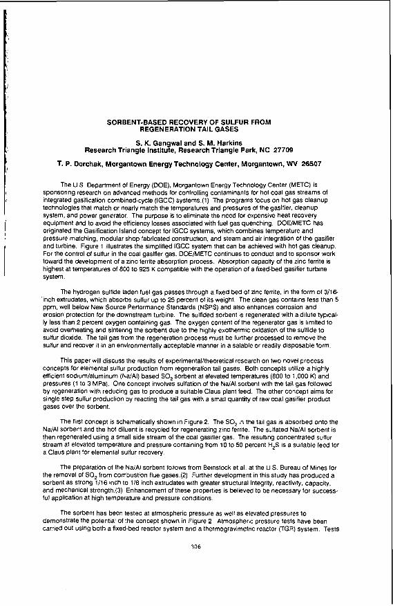
The U S Department of Energy (DOE), Morgantown Energy Technology Center (METC) is sponsoring research on advanced methods for controlling contaminants for hot Coal gas Streams of integrated gasification combined-cycle (IGCC) systems.(l) The programs focus on hot gas cleanup technologies that match or nearly match the temperatures and pressures of the gasifier, CleanUp system, and power generator. The purpose is to eliminate the need for expensive heat recovery equipment and to avoid the efficiency losses associated with fuel gas quenching. DOE/METC has originated the Gasification Island concept for IGCC systems, which combines temperature and pressure matching, modular shop fabricated construction, and steam and air integration of the gasifier and turbine. Figure 1 illustrates the simplified IGCC system that can be achieved with hot gas cleanup. For the control of sulfur in the coal gasifier gas, DOE/METC continues to conduct and to sponsor work toward the development of a zinc ferrite absorption process. Absorption capacity of the zinc ferrite is highest at temperatures of 800 to 925 K compatible with the operation of a fixed-bed gasifier turbine system.
The hydrogen sulfide laden fuel gas passes through a fixed bed of zinc ferrite, in the form of 3/1& inch extrudates. which absorbs sulfur up to 25 percent of its weight. The clean gas contains less than 5 ppm, well below New Source Performance Standards (NSPS) and also enhances corrosion and erosion protection for the downstream turbine. The sulfided sorbent is regenerated with a dilute typical- ly less than 2 percent oxygen containing gas. The oxygen content of the regenerator gas is limited to avoid overheating and sintering the sorbent due to the highly exothermic oxidation of the sullide to sulfur dioxide. The tail gas from the regeneration process must be further processed to remove the sulfur and recover it in an environmentally acceptable manner in a salable or readily disposable form.
This paper will discuss the results of experimental/theoretical research on two novel process concepts for elemental sulfur production from regeneration tail gases. Both concepts utilize a highly efficient sodium/aluminum (Na/AI) based SO, sorbent at elevated temperatures (800 to 1,000 K) and pressures (1 to 3 MPa). One concept involves sulfation of the NdAl sorbent with the tail gas followed by regeneration with reducing gas to produce a suitable Claus plant feed. The other concept aims for single Step sulfur production by reacting the tail gas with a small quantity of raw coal gasifier product gases over the sorbent.
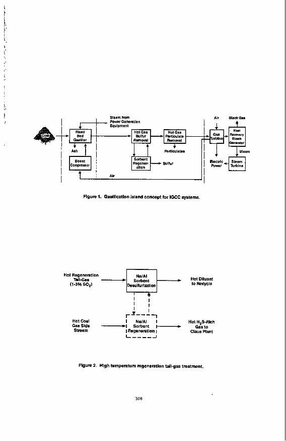
The first concept is schematically shown in Figure 2. The SO, in the tail gas is absorbed onto the Na/AI sorbent and the hot diluent is recycled for regenerating zinc ferrite. The sulfated NdAI sorbent is ?hen regenerated using a small side stream of the coal gasifier gas. The resulting concentrated sulfur stream at elevated temperature and pressure containing from 10 to 50 percent H,S is a suitable feed for a Claus plant for elemental sulfur recovery.
The preparation of the NdAI sorbent follows from Beinstock et al. at the US. Bureau of Mines for the removal of SO, from combustion flue gases.(2) Further development in this study has produced a sorbent as strong 1/16 inch to 1/8 inch extrudates with greater structural integrity, reactivity, capacity, and mechanical strength.(3) Enhancement of these properties is believed to be necessary for success- ful application at high temperature and pressure conditions
The sorbent has been tested at atmospheric pressure as well as elevated pressures to demonstrate the potential of the concept shown in Figure 2. Atmospheric pressure tests have been carried out using both a fixed-bed reactor system and a thermogravimetric reactor (TGR) system. Tests
have been conducted at 800 to 975 K with a tail gas containing 1 to 2 percent SO,. These conditions are representative of zinc ferrite regeneration tail gas. Atmospheric pressure tests have shown that the sorbent can absorb SO, u p to 40 percent of its weight. The sorbent can be regenerated while maintaining a crush strength greater than 13.5 N/mm over 20 sulfationhegeneration cycles. In atmo- spheric pressure fixed-bed tests, the sorbent demonstrated high efficiency in absorbing SO, by reducing it from 2 percent to less than 10 ppmv. This essentially "zero" prebreakthrough level of SO, was maintained for over 2 hours at a space velocity of 2000 h'. Approximately 30 percent by weight SO, was absorbed prior to 100 ppm SO, breakthrough. Regenerations of the sorbent with coal gasifier gas and hydrogen in separate tests produced H,S rich gas streams containing up to 16.4 and 60 percent H,S, respectively.
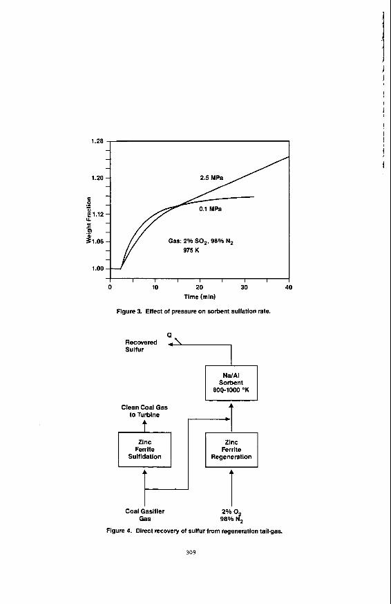
kinetics that could be used to predict fixed-bed sorbent performance at elevated pressure. Figure 3 compares the atmospheric pressure sulfation rate to sulfation rate at 2.5 MPa. As can be seen, the overall SO, absorption capacity as a function of time is significantly higher at 2.5 MPa. This indicates that it will be possible to sulfate a fixed-bed of the sorbent to significantly greater levels at elevated pressures than at atmospheric pressure, prior to breakthrough. Following completion of measurement of elevated pressure sulfation/regeneration kinetics, a fixed-bed absorption/regeneration model will be developed to predict sorbent capacity at breakthrough in fixed-bed reactors. Bench-scale tests will then be carried out to demonstrate the concept at elevated pressures.
Elevated pressure TGR tests have recently been initiated to evaluate sulfation and regeneration
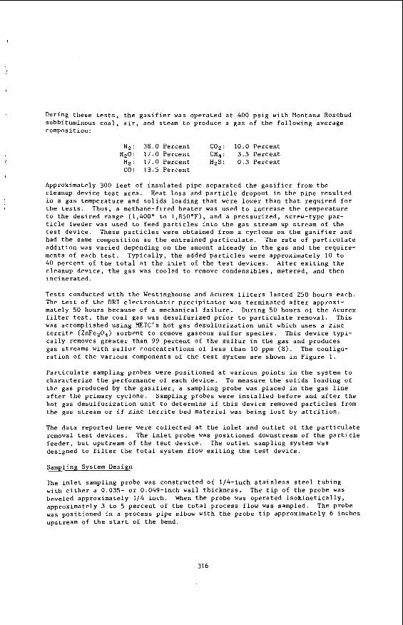
Elemental sulfur has been observed on the surface of the sorbent following sulfationlregeneration cycles. Also significant amounts of elemental sulfur elutes from the sorbent after breakthrough has been achieved during sulfation. This has suggested a second concept for direct recovery of elemental sulfur from regeneration tail gases which if successful would result in significant reduction of the burden on the Claus plant. Ideally this concept (shown schematically in Figure 4) may allow the complete elimination of the Claus plant. A thermodynamic analysis of potential sulfur forming reactions of H,. SO,. CO, H,S. CO,. and steam indicates that 96 to 98 percent of the SO, can be potentially converted to elemental sulfur at 800 to 1,000 K and 2.5 MPa. A few bench-scale tests will be carried out in the future to assess the potential of this concept.
References
1. U.S. Department of Energy, "Hot Gas Cleanup for Electric Power Generation Systems," Morgantown Energy Technology Center, DE86006607. May (1986).
Bienstock, D., J. H. Field, and J. G. Myers, Bureau of Mines, Department of Investigations. 5735,
Gangwal, S. K., S. M. Harkins, and M. C. Woods, "Disposal of Off-Gases from Hot Gas Desulfurization Processes," Yearly Technical Status Report, Contract No. DE-AC21-86MC 23260, to be published (1987).
2. PB 192542 (1961).
3
I
307
i T I
Steam from Power Generetlon Equlpment
Regener- Sulfur Boost Compressor
I Alr
Figure 1. Gaslflcatlon island concept for IGCC systems.
Hot Regeneration Hot Dlluent
(1-3% SO,) Desulfurization
I I 1
Hot Coal I NdAI I Hot H,S-Rich GasSlde -1 Sorbent I-+ Gasto Stream I Regeneration 1
rI---
Claus Plant
Flgure 2. Hlgh temperature regeneration tallgas treatment.
308
”’$ 1.20 2.5 M P a A
I I I I I I I I I I 0 10 20 30 40
Time (min)
Figure 3. Effect of pressure on sorbent sulfation rate.
Recovered Sulfur
Clean Coal Gas to Turbine
Ferrite Sulfldation
Sorbent
Ferrite Regeneration
Coal Gasifier 2% 0 Gas 98% d2
Figure 4. Direct recovery of sulfur from regeneration tail-gas.
309
SEPARATION OF GAS MIXTURES BY TRANSITION-METAL COMPLEXES
M. A . Li lga, R. T. Hallen, D. A . Nelson
B a t t e l l e , Pac i f ic Northwest Laboratory P.O. Box 999
Richland, WA 99352
INTRODUCTION
The se lec t ive separat ion o r p u r i f i r a t i o n of gases, espec ia l ly hydrogen and CO, i s highly des i rab le i n processes u t i l i z i n g product gas from coal g a s i f i c a t i o n . However, gas separat ion i s a d i f f i c u l t and energy intensive process. The develop- ment of new and innovative methodologies t o se lec t ive ly and e f f i c i e n t l y separa te s p e c i f i c gas components from mixed-gas streams would s i g n i f i c a n t l y reduce the cos t and complexity of product gas production and processing. For example, e f f i c i e n t H2 separation from synthesis gas could make coal an a t t r a c t i v e fu ture source of H2 f o r use as a fuel o r chemical feedstock. In addi t ion, this technology could have a s ign i f icant impact on processes not d i r e c t l y associated w i t h coal g a s i f i c a t i o n i n which hydrogen i s l o s t in a waste stream. These processes include ammonia manufacture, reduction of meta l l ic oxide ores , and hydrogenation of f a t s and o i l s . Thus, wide-ranging appl icat ions e x i s t f o r hydrogen separat ion and recovery technologies.
Current separat ion technologies a r e i n e f f i c i e n t o r non-selective. p le , recovery of H2 from Pressure Swing Adsorption i s on the orqfir of 80%. inef fec t ive with feeds containing l e s s than 50% H2. process f o r CO recovery i s highly moisture sens i t ive , requir ing removal of water from feed streams. Membranes a r e inherent ly energy e f f i c i e n t but systems, such a s PRISMTM, cannot separa te H2 from C02.
as s e l e c t i v e agents f o r the separat ion of syngas components from gas mixtures. Transition-metal complexes a r e known which reac t revers ibly w i t h gases such a s He, CO, 02, and CO2. This revers ib le binding can be used t o t r a n s f e r t h e gas from a region of high par t ia l pressure t o a region of lower p a r t i a l pressure. The selec- t i v i t y of t r a n s f e r i s determined pr imari ly by the s e l e c t i v i t y of the metal i n binding a spec i f ic gas. The nature of the ligands surrounding the metal has a large influence on the s e l e c t i v i t y and r e v e r s i b i l i t y and we have successfu l ly used ligand modification t o prepare complexes t h a t have improved proper t ies f o r H2 o r CO binding. examples of metal complexes under study wil l be discussed.
APPLICATION OF METAL COMPLEXES TO GAS SEPARATION
For exam- PSA i s
The COSORB
The Pac i f ic Northwest Laboratory (PNL) i s examining t ransi t ion-metal complexes
Applications of metal complexes t o gas separat ion and two s p e c i f i c
Two gas separat ion systems which take advantage of s e l e c t i v e , revers ib le gas binding by t ransi t ion-metal complexes a r e absorption/desorption and f a c i l i t a t e d t ranspor t membrane systems. 1 and i t s operation i s i l l u s t r a t e d f o r CO separat ion. en ters the bottom of t h e absorber column and encounters a counter-current flow of solut ion containing a metal complex. Non-reactive feed gases e x i t the top of the absorber while CO i s t ransported t o the s t r i p p e r column i n the form of a CO/metal complex. Heat and an i n e r t s t r i p p i n g gas re lease the C O from the metal complex in the s t r i p p e r column. vola t i l i zed solvent is condensed and returned t o t h e system. containing regenerated metal complex i s recycled t o the top of the absorber columpM and the cycle begins again. process and allows f o r continuous gas separat ion. Any gas could be separated from a feed stream by this process assuming an appropriate metal complex/solvent system
A two-column apparatus used a t PNL i s shown i n Figure I n l e t gas containing CO
CO product gas e x i t s the top of the s t r i p p e r column and The so lu t ion
This apparatus i s s imi la r t o t h a t used i n the COSORB
310
spec i f ic f o r t h a t gas i s ava i lab le . l a rge amounts of c a r r i e r required and the interference of s o l u b i l i t y o f undesired gases in the solvent .
f a c i l i t a t e d t ranspor t agent, o f f e r the poten t ia l f o r high s e l e c t i v i t y and increased f lux . This type of system i s i l l u s t r a t e d i n Figure 2 f o r H separat ion. The dr iving force t o separa t ion i s a pressure gradient across t2e membrane. Hydrogen enter ing the membrane on the high pressure s ide reac ts w i t h a metal complex. The metallhydrogen complex d i f fuses across the membrane where H2 i s re leased i n the HZ- lean environment and product H2 leaves the membrane and i s removed. A concentra- t i o n gradient d r i v e s t h e metal complex back across the membrane and more H2 i s bound the continue t h e cycle. The function of the metal complex Is t o a c t as a s p e c i f i c c a r r i e r f o r H and serves t o increase the e f fec t ive H concentration in t h e membrane r e l a t i v e $0 the undesired gases. Thus, s e l e c t i v i f y f o r H2 i s high, allowing the use of th inner membranes resu l t ing i n a grea te r f lux. Permeability and s e l e c t i v i t y i n these systems a r e expected t o be s i g n i f i c a n t l y g r e a t e r than f o r dry or l iquid-wet ted membranes,
PALLADIUM COMPLEXES
Potent ia l drawbacks include the r e l a t i v e l y
Immobilized l i q u i d membrane systems, in which the metal complex ac ts as a
Palladium dimer complexes were evaluated f o r t h e i r a b i l i t y t o revers ibly bind Kinet ic and thermodynamic data f o r these complexes (X = NCO, C 1 , CO (Equation 1).
Br, I) ind ica te t h a t hal ide subs t i tu t ion grea t ly inf luences the binding of C O (1). For example, t h e equi l ibr ium constant , K , f o r CO binding follows t h e order NCO > C1 > Br ) I where K f o r the NCO complex i s approximately 300 times t h a t of t h e iodide complex. i n k-1, t h e r a t e of CO d i ssoc ia t ion .
Spec i f ic i ty f o r CO i s high. not i n t e r f e r e with CO binding. HzS was found t o reac t i n a nove? way t o re lease HZ according t o Equation 2 (2) .
This d i f f e r e n c e i n equilibrium constant i s pr imari ly due t o d i f fe rences
Gases including C02, N 2 , H2, 0 and ethylene do
I 1 I ’f I PIlZP, / PPI12 PhA’, /PPh>
CHz CHz
Equilibrium d a t a f o r t h e bromide complex indicated s u i t a b l e r e v e r s i b i l i t y over the temperature and CO pressure ranges of i n t e r e s t . This complex was chosen f o r
311
bench-scale experiments in the absorber/stripper system shown in Figure 1 (3). Presence of the complex enhances transfer of CO by an order of magnitude and the system functions to separate CO from Np. With a five-component mixture (CO, CO2, H2, CH4, and N2) a combination of chemical complexation of CO and the solubility of C02 and CH4 in the solvent resulted in significant transfer of these gases to the stripper. Little H2 was transferred and an H2-rich gas stream was produced indi- cating the potential of this system for H2 separation from a low-btu gas mixture. A cost analysis indicated that the initial costs of palladium were not necessarily prohibitive but to compete with existing technology the lifetime of the complex must be at least one year.
CHROMIUM COMPLEXES
The reaction of H2 with [CpCr(C0)3]2 (Cp = cyclopentadienyl, C5H5) was
It has also been reported that the pure reported by Fischer, et al. (4,5) to occur at 70°C and 150 atm H2 to afford the monomeric hydride complex CpCr(C0)3H. monomeric hydride complex evolves H2 when heated to 80°C, its melting point. initial objective was to determine the temperature and H2 pressure conditions required to carry out the reversible H2 binding in solution (Equation 3).
Our
R
d a
Derivatives of the complex were also prepared to study the effects of electron- withdrawing groups on the cyclopentadienyl ligand (R = C02CH ) on Equation 3'. investigation has demonstrated that the reaction of H2 with fCpCr(C0)3]2 is much more facile than previously reported. is complete before a spectrum can be taken. This dimer is found to react with 1 atm H2 slowly at room temperature but faster at 65"C, reaching completion in 0.5 hours. for 2 hours. inactive complex is formed. binding but regeneration appeared to be easier with 10% conversion at 90°C after two hours. in which two chromium centers interact. improved by 1 inking the cyclopentadienyl groups together, since hydrogen formation would then be unimolecular.
Our
At 10 atm and room temperature, the reaction
Regeneration to the extent of about 5% can be achieved by heating to 100°C
The substituted complex shows similar activity for H2 H2 is rapidly lost upon photolysis, however, CO is also lost and an
Regeneration may be difficult because it involves a bimolecular process It is possible that regeneration will be
CONCLUSIONS
Selective transition-metal complexes can enhance gas transport in gas separ- ation processes. of the ligand environment to improve binding characteristics. selectivity for specific gas components is attainable. not be prohibitively expensive.
Properties of complexes can be tailored by chemical modification As a result, high
In addition, complexes need
312
ACKNOWLEDGMENT
This research was supported by the U.S. Department o f Energy, Morgantown Energy Technology Center under con t rac t DE-AC06-76RLO 1830.
REFERENCES
(1) Lee, C. L.; James, 6. R.; Nelson, D. A.; Hal len, R. T. Organometol
(2) James, 8. R.; Lee, C. L.; L i l g a , M. A.; Nelson, D. A. U.S. Patent
3, 1360.
1987.
ics, 1984,
693 875,
( 3 ) Lyke, S. E.; L i l g a , M. A.; Ozanich, R. M.; Nelson, D. A. I n d . Eng. Chem. Prod. Res. Dev., 1986, 25, 517.
(4) Fischer, E. 0. Inorg. Synth., 1963, 7, 136.
(5) Fischer, E. 0.; Hafner, W.; S tah l , H. 0. Z. Anorg. Allgem. Chem., 1955, 282, 47.
313
Vent 1 _ _ _ G a s Streams
d?-------' -Liquid Loop
I I I I
I I
Other Lines -
--=.""'PI n cw
Heaters
,------
Pump Cooler Stripper
FIGURE 1. Absorber/Stripper Apparatus
LOW - H Z Pressure
FIGURE 2. Facilitated Transport o f H2 by a Membrane Containing a Dissolved Metal Complex
314
The Removal of I m p u r i t i e s from Hot Coal-Derived Gas by F i l t r a t i o n
by
T . Gr indley and R . G . Logan U.S. Department of Energy
Morgantown Energy Technology Center MOKgantOWn, WV 26505
A t t h e Morgantown Energy Technology Center (METC) of t h e U.S. Department of Energy, a n e f f o r t is underway t o c l e a n h o t coa l -der ived gas t o a s u f f i c i e n t p u r i t y f o r combustion i n h e a t engines and o t h e r a p p l i c a t i o n s . Experiments were conducted i n which t h e h o t product g a s , raw and d e s u l f u r i z e d , from a f lu id-bed coa l g a s i f i e r was f i l t e r e d a t t empera tures up t o 1,600°F, p r e s s u r e s up t o 250 p s i g , and f low r a t e s up t o 2 ,500 s c f h . P a r t i c u l a t e and condensate samples were c o l l e c t e d a t t h e i n l e t and o u t l e t of t h e f i l t e r s and analyzed f o r 10 meta ls which a r e common c o n s t i t u e n t s of c o a l ash . The r e s u l t s were used t o determine how f i l t r a t i o n of p a r t i c l e s from a gas s t ream a t h igh tempera tures a f f e c t e d metal c o n c e n t r a t i o n s i n t h e g a s . I n g e n e r a l , t h e removal e f f i c i e n c y f o r t h e meta ls c o r r e l a t e d wi th t h e p a r t i c u l a t e removal e f f i c i e n c y .
I n t r o d u c t i o n
Under t h e Advanced Environmental Control Technology Program e s t a b l i s h e d i n 1979 by t h e Department of Energy (11, MOKgantOWn Energy Technology Center has been a c t i v e l y engaged i n t h e development of technology necessary t o c o n t r o l contaminants from c o a l g a s i f i c a t i o n t h a t a r e d e l e t e r i o u s t o gas t u r b i n e s and hazardous t o t h e environment . A s i g n i f i c a n t p a r t of t h i s e f f o r t has been con- cerned wi th p a r t i c u l a t e and t r a c e m e t a l , p a r t i c u l a r l y a l k a l i m e t a l s , removal from t h e hot gas s t reams. Three hot gas f i l t r a t i o n devices developed i n t h e program by c o n t r a c t o r s were t e s t e d a t METC t o de te rmine t h e i r performance i n a n a c t u a l ho t gas stream produced by a s m a l l - s c a l e , f lu id-bed g a s i f i e r ( 2 ) . The t h r e e devices were a Westinghouse ceramic c ross - f low f i l t e r , an Acurex ceramic bag f i l t e r , and a n e l e c t r o s t a t i c p r e c i p i t a t o r developed by Denver Research I n s t i t u t e . D e t a i l s o f t h e d e s i g n of t h e s e devices and r e s u l t s of t h e work t o d a t e have been r e p o r t e d i n a s e r i e s of c o n t r a c t o r review meetings ( 3 - 9 )
Although t h e p r i n c i p a l purpose of t h i s s e r i e s o f t e s t s was t o measure t h e par - t i c u l a t e removal e f f i c i e n c y of t h e h o t gas f i l t e r s a t t empera tures up t o 1,850°F, they a f f o r d e d t h e oppor tuni ty t o a l s o measure t h e c o n c e n t r a t i o n of 10 m e t a l s , which a r e common c o n s t i t u e n t s of c o a l a s h , i n t h e gas s t ream. Spe- c i f i c a l l y , i t was d e s i r e d t o de te rmine whether removal of p a r t i c l e s from a c o a l gas a t t empera tures up t o 1,850°F would a f f e c t t h e downstream concent ra t ion of t r a c e s p e c i e s of m e t a l s such a s sodium and potassium. The r e s u l t s of t h e experiment a r e r e p o r t e d i n t h i s paper .
Experimental
The low-Btu coa l gas used dur ing these t es t s was produced by METC's advanced concepts f lu id-bed g a s i f i e r . The g a s i f i e r was des igned t o o p e r a t e w i t h a wide range of coa ls a t p r e s s u r e s of 200 t o 1 ,000 p s i g and tempera tures up t o 1,900°F The g a s i f i e r i s used a s a source of low- t o medium-Btu gas f o r use i n t e s t i n g downstream components and a n a l y t i c a l i n s t r u m e n t a t i o n .
315
,
During these tests, t h e g a s i f i e r was opera ted a t 400 p s i g wi th Montana Rosebud subbituminous c o a l , a i r , and s t e a m t o produce a gas of t h e fo l lowing average composition:
NZ: 38.0 Percent C O z : 10.0 Percent H z O : 1 7 . 0 Percent CH4: 3 .5 Percent
Approximately 300 f e e t of i n s u l a t e d p i p e s e p a r a t e d t h e g a s i f i e r from t h e cleanup device t e s t a r e a . Heat loss and p a r t i c l e dropout i n t h e p i p e r e s u l t e d i n a gas temperature and s o l i d s loading t h a t were lower than t h a t r e q u i r e d f o r t h e t e s t s . Thus, a methane-f i red h e a t e r was used t o i n c r e a s e t h e tempera ture t o t h e d e s i r e d range (1,400° t o 1 ,850°F) , and a p r e s s u r i z e d , screw-type par - t i c l e feeder was used t o feed p a r t i c l e s i n t o t h e gas s t ream up s t ream of t h e t e s t device . These p a r t i c l e s were obta ined from a cyclone on t h e g a s i f i e r and had t h e same composi t ion a s t h e e n t r a i n e d p a r t i c u l a t e . The r a t e of p a r t i c u l a t e a d d i t i o n was v a r i e d depending on t h e amount a l r e a d y i n t h e gas and t h e r e q u i r e - ments of each t e s t . T y p i c a l l y , the added p a r t i c l e s were approximately 10 t o 40 p e r c e n t of t h e t o t a l a t t h e i n l e t of t h e t e s t devices . A f t e r e x i t i n g t h e cleanup device , t h e gas was cooled t o remove condens ib les , metered, and then i n c i n e r a t e d .
T e s t s conducted wi th t h e Westinghouse and Acurex f i l t e r s l a s t e d 250 hours each. The t e s t of t h e D R I e l e c t r o s t a t i c p r e c i p i t a t o r was te rmina ted a f t e r approxi- mately 50 hours because of a mechanical f a i l u r e . During 50 hours of t h e Acurex f i l t e r t e s t , t h e c o a l gas was d e s u l f u r i z e d p r i o r t o p a r t i c u l a t e removal. This was accomplished u s i n g M E T C ' s ho t gas d e s u l f u r i z a t i o n u n i t which uses a z i n c f e r r i t e (ZnFep04) s o r b e n t t o remove gaseous s u l f u r s p e c i e s . This d e v i c e t y p i - c a l l y removes g r e a t e r than 99 p e r c e n t of t h e s u l f u r i n t h e gas and produces gas s t reams wi th s u l f u r c o n c e n t r a t i o n s of l e s s t h a n 10 ppm ( 8 ) . The configu- r a t i o n of t h e v a r i o u s components of t h e t e s t system a r e shown i n F i g u r e 1.
P a r t i c u l a t e sampling probes were p o s i t i o n e d a t v a r i o u s p o i n t s i n t h e system t o c h a r a c t e r i z e t h e performance of each device . To measure t h e s o l i d s loading of the gas produced by t h e g a s i f i e r , a sampling probe was p laced i n t h e gas l i n e a f t e r t h e primary cyc lone . Sampling probes were i n s t a l l e d b e f o r e and a f t e r t h e hot gas d e s u l f u r i z a t i o n u n i t t o determine i f t h i s device removed p a r t i c l e s from t h e gas s t ream o r i f z i n c f e r r i t e bed m a t e r i a l was be ing l o s t by a t t r i t i o n .
The d a t a repor ted h e r e were c o l l e c t e d a t t h e i n l e t and o u t l e t of t h e p a r t i c u l a t e removal t e s t devices . The i n l e t probe was p o s i t i o n e d downstream of t h e p a r t i c l e f e e d e r , bu t upstream of t h e t e s t d e v i c e . The o u t l e t sampling system was designed t o f i l t e r t h e t o t a l system flow e x i t i n g t h e t e s t device .
Sampling System Design
The i n l e t sampling probe was cons t ruc ted of 1/4- inch s t a i n l e s s s t e e l tub ing wi th e i t h e r a 0.035- o r 0.049-inch w a l l t h i c k n e s s . The t i p of t h e probe was beveled approximately 1 / 4 inch . When t h e probe was opera ted i s o k i n e t i c a l l y , approximately 3 t o 5 p e r c e n t of t h e t o t a l p rocess f low was sampled. was p o s i t i o n e d i n a process p i p e elbow wi th t h e probe t i p approximately 6 inches upstream of t h e s t a r t of t h e bend.
The probe
316
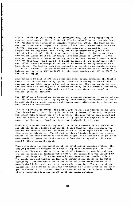
Figure 2 shows the inlet sample line configuration. The particulate samples were collected using 1.37- by 3.94-inch (35- by 100-millimeter), rounded bot- tom, alundum ceramic extraction thimbles (Norton No. 6406). The thimbles are designed to withstand temperatures up to 2,600°F, and pressure drops of up to 100 psi. The entire sampling line and gate valves were wrapped in high- temperature heating tapes, insulation, and a high-temperature glass cloth (Colombia Fiberglass). The heating tapes, controlled by digital temperature controllers (Omega Model No. CS4001KF), were maintained at l,OOO°F. It was necessary to use an alternative heating method for the thimble holders because of their high mass. An 8-foot by 1/8-inch heating rod (ARI Industries, Inc.) was coiled around the elongated section of a thimble holder by means of metal hose clamps. The heating rods were powered from variable autotransformers set at 100 to 120 volts. The gas temperature at the downstream end of the thimble holders was typically 350° to 400'F for the inlet samples and 700° to 800°F for the outlet samples.
Approximately 30 feet of 3/8-inch stainless steel tubing separated the thimble holder from the flow monitoring system. This was necessary because of the shortage of available space in the test device area. The flow monitoring sys- tem consisted of a cooling coil, a condensate trap, and a flowmeter (rotameter). Condensate samples were collected in a 1-liter, stainless steel sampling cylinder (Hoke No. 8LD1000).
The flowmeter, a temperature indicator and a pressure gauge were located between two 1/4-inch needle valves. By adjusting these valves, the desired flow could be maintained at a known pressure and temperature. After metering, the gas was exhausted to an incinerator.
To take a particulate sample, the probe, gate valves, and thimble holder were first heated for 1 hour. Just prior to starting sample collection, the probe was purged with nitrogen for 3 to 5 seconds-. The gate valves were opened and then the needle valves on the flow monitoring system were adjusted to set the sample gas flow rate. Sampling times were typically 1 to 2 hours.
After sample collection was completed, the thimble holders were disconnected and allowed to cool before removing the loaded thimble. The condensate was drained and measured so that the contribution of water vapor to the total gas flow could be calculated. The 30-foot section of tubing between the thimble holder and the flow monitoring system was purged with steam and nitrogen after each sample to remove residual condensate from the tubing walls. This was added to the condensate sample.
Figure 3 depicts the configuration of the total outlet sampling system. The sampling system was designed as a bypass loop from the main gas line. The entire gas flow was filtered using two thimble holders in parallel and then the gas was cooled to condense water vapor. The sample loop was isolated by gate valves (Vogt No. 821) upstream and downstream of the thimble holders. The sample loop and thimble holders were insulated and heated as described previously. The condensate was collected in stainless steel vessels which were drained before and just after each outlet sampling. The weight of the condensates was recorded s o that the contribution of water vapor to the total gas flow could be calculated. Metal concentrations in the condensate could also be translated into equivalent total gas concentrations.
318
L F s g
7
Sample Prepara t ion
Thimbles were hea ted i n an oven a t 250°F f o r approximately 30 minutes , cooled i n a d e s i c c a t o r , and weighed on an a n a l y t i c a l ba lance p r i o r t o be ing loaded i n t o a thimble holder . A f t e r c o l l e c t i n g a p a r t i c u l a t e sample, t h e thimble h o l d e r s were ex t remely h o t and were allowed t o cool f o r approximately 30 min- u t e s . The holder w a s t h e n taken a p a r t and t h e th imble removed. The th imble , conta in ing t h e p a r t i c u l a t e sample, was p laced i n an oven a t 250'F f o r approxi- mately 45 minutes . A f t e r c o o l i n g , t h e th imble was weighed a g a i n . The d i f f e r - ence i n t h e i n i t i a l and f i n a l weights was taken t o b e t h e weight of p a r t i c l e s on t h e thimble. T y p i c a l l y , a small f r a c t i o n of t h e p a r t i c l e s escaped around t h e edge of a th imble whi le i n t h e h o l d e r . These p a r t i c l e s were c o l l e c t e d t o g e t h e r with t h e condensa tes and f i l t e r e d o u t us ing Gelman M e t r i c e l , 47-mi l l imeter , O.G5-micron, Type GA-6 f i l t e r s under vacuum. The sample was then d r i e d i n an oven, cooled i n a d e s i c c a t o r , and weighed. This weight was added t o t h e weight of p a r t i c l e s c o l l e c t e d on t h e th imble t o y i e l d a t o t a l sample weight. P o r t i o n s of t h e p a r t i c l e s c o l l e c t e d i n t h e th imbles were sub- m i t t e d f o r p a r t i c l e s ize , u l t i m a t e , and meta ls a n a l y s e s . P a r t i c l e s f i l t e r e d from t h e condensates were not used f o r t h e chemical a n a l y s e s because o f t h e p o s s i b i l i t y t h a t l e a c h i n g had a f f e c t e d t h e i r composi t ion. P a r t i c l e s i z e a n a l y s e s were performed us ing a Model No. T A I I C o u l t e r Counter . The pH of t h e condensates was a d j u s t e d t o 5 2 .0 by a d d i t i o n o f n i t r i c a c i d , and s t o r e d i n polye thylene b o t t l e s .
The s o l i d and condensa te samples were analyzed f o r 10 meta ls using a Perkin- E l m e r Model 5000 a tomic a b s o r p t i o n spec t rophotometer and a S p e c t r a m e t r i c s , I n c . , d i r e c t plasma atomic emiss ion spec t rometer . A l i t h i u m metaborate f u s i o n was performed on t h e s o l i d samples i n order t o g e n e r a t e a l i q u i d f o r t h e s e ana lyses .
Data Analysis
A s descr ibed in t h e exper imenta l s e c t i o n , t h e c o n c e n t r a t i o n s of t h e metals i n t h e gas s t ream were obta ined by measuring t h e i r amounts i n t h e p a r t i c l e s and condensate c o l l e c t e d u t i l i z i n g sampling devices a t t h e i n l e t and o u t l e t of t h e t e s t devices , and r e l a t i n g them t o t h e q u a n t i t y of gas which had flowed through t h e devices . In t h e c o u r s e of t h e t es t s , 18 sets of i n l e t l o u t l e t samples were taken f o r t h e Westinghouse ceramic c ross - f low f i l t e r , 23 f o r t h e Acurex f a b r i c bag f i l t e r , and 10 f o r t h e Denver Research I n s t i t u t e e l e c t r o s t a t i c p r e c i p i t a t o r .
The performance of t h e 3 f i l t e r s a r e summarized i n Table 1, which g i v e s t h e average p a r t i c u l a t e l o a d i n g of t h e i n l e t and o u t l e t gas t o g e t h e r wi th t h e c a l c u l a t e d removal e f f i c i e n c y and t h e mean p a r t i c l e d iameter . u l t i m a t e a n a l y s e s of t h e p a r t i c u l a t e samples a r e d e t a i l e d i n Table 2 , and Table 3 g ives t h e a v e r a g e gas concent ra t ions of p a r t i c l e s , a s h , and 10 meta ls . The c a l c u l a t e d v a l u e s o f removal e f f i c i e n c y a r e a l s o inc luded .
Genera l ly , t h e Westinghouse f i l t e r had t h e h i g h e s t p a r t i c u l a t e removal e f f i - c iency followed by t h e Acurex and DRI f i l t e r s . Removal e f f i c i e n c y tended t o i n c r e a s e wi th i n l e t p a r t i c l e loading . The Westinghouse f i l t e r tended t o r e s u l t i n a lower o u t l e t p a r t i c l e loading t h a n t h e Acurex or D R I f i l t e r s because o f i t s h igher p a r t i c u l a t e removal e f f i c i e n c y .
S t a t i s t i c a l a n a l y s i s o f t h e d a t a i n d i c a t e s t h a t , though not s t r o n g , t h e r e i s a c o r r e l a t i o n between p a r t i c u l a t e removal e f f i c i e n c y and each of t h e metal removal e f f i c i e n c i e s . The meta l removal e f f i c i e n c i e s s i g n i f i c a n t l y a r e some
The average
321
2 t o 6 percentage p o i n t s lower, on average , than t h e p a r t i c u l a t e removal e f f i - c iency. t i c u l a t e on pass ing through t h e f i l t e r s , f o r a s i m i l a r r e s u l t i s obta ined when compared wi th t h e a s h removal e f f i c i e n c i e s . This may be due t o a h igher meta ls concent ra t ion i n t h e s m a l l e r p a r t i c l e s p a s s i n g through t h e f i l t e r s .
A p a r t i c u l a r l y i n t e r e s t i n g r e s u l t i s t h a t metal removal e f f i c i e n c i e s could n o t be shown t o be dependent on o p e r a t i n g c o n d i t i o n s which v a r i e d i n t h e ranges: temperature -- 800° t o 1,'600°F; p r e s s u r e -- 140 t o 250 p s i g ; and flow r a t e -- 1,300 t o 2,500 s c f h . This i s e s p e c i a l l y impor tan t f o r t h e c a s e of t h e a l k a l i meta ls , sodium and potassium, s i n c e it i s specula ted t h a t , a t h i g h e r tempera- t u r e s and lower p r e s s u r e s , t h e s e r e l a t i v e l y v o l a t i l e s p e c i e s might p a s s more r e a d i l y through t h e hot g a s f i l t e r s .
The average measured removal e f f i c i e n c y f o r t h e meta ls v a r i e d s l i g h t l y among themselves . This i s shown i n Table 4 . In Table 5 , t h e meta l c o n c e n t r a t i o n s a r e expressed a s t h e average percentage of t h e t o t a l sum of t h e t e n meta ls f o r bo th t h e i n l e t and o u t l e t . These da ta show t h a t t h e r e was a n enrichment of Ca i n the o u t l e t gas . This was most apparent dur ing t h e Westinghouse t es t dur ing which t h e average Ca c o n c e n t r a t i o n increased from 20 p e r c e n t of t h e t o t a l of t h e meta ls a t t h e i n l e t t o 28 p e r c e n t of t h e t o t a l a t t h e o u t l e t . The source of t h i s enrichment was b e l i e v e d t o be t h e r e f r a c t o r y l i n i n g of t h e p i p i n g . This a s s e r t i o n i s suppor ted by t h e f a c t t h a t a f t e r t h e Westinghouse t e s t , t h e o r i g i n a l r e f r a c t o r y was rep laced wi th a new r e f r a c t o r y t h a t was r a t e d f o r a h igher temperature . Subsequent ly , dur ing t h e Acurex and DRI tests Ca e n r i c h - ment of t h e o u t l e t gas cont inued b u t t o a l e s s e r degree. The o u t l e t gas was enr iched i n Mg and a l k a l i s a s w e l l , bu t t o a l e s s e r degree than Ca. These metals a r e a l s o components of t h e r e f r a c t o r y . The composi t ion of t h e two r e f r a c t o r i e s i s shown i n Table 6 .
During 50 hours of t h e Acurex f i l t e r t e s t , t h e h o t gas t o t h e f i l t e r was f i r s t d e s u l f u r i z e d by passage through a f ixed bed of z i n c f e r r i t e (8 ) . The r e s u l t i n g gas tended t o have a lower p a r t i c u l a t e loading compris ing s m a l l e r s i z e p a r t i - c l e s . No p a r t i c u l a t e was added t o the gas s t ream dur ing t h i s p e r i o d . However, t h e p a r t i c u l a t e removal e f f i c i e n c y dur ing t h i s p e r i o d d i d not d i f f e r s i g n i f i - c a n t l y from t e s t p e r i o d s when raw gas was u t i l i z e d . Nor was it found t h a t t h e p a r t i c u l a t e was enr iched i n z i n c , which might have been a consequence o f a t t r i - t i o n o r v a p o r i z a t i o n of t h e z i n c f e r r i t e bed. The only meta l which showed a s i g n i f i c a n t d i f f e r e n c e i n removal e f f i c i e n c y d u r i n g t h e t es t us ing d e s u l f u r i z e d gas was n i c k e l . The e f f i c i e n c y dur ing t h e d e s u l f u r i z a t i o n t e s t was lower.
This cannot be accounted f o r by g a s i f i c a t i o n of carbon i n t h e par -
322
TABLE 1. CHARACTERIZATION OF PARTICLES I N THE HOT COAL GAS STREAM
Average Standard Average Average P a r t i c u l a t e Devia t ion Average Average
Loading Loading E f f i c i e n c y E f f i c i e n c y Diameter Diameter (mg/ s c f ) (mg/scf) % % (micron) (micron)
Acurex, D R 1 2 38.61 31.48 5 . 3 8 1.50 19.54 0.79 1 .41
+: P l i b r i c o Company Labora tory Report . Ref rac tory maximum tempera ture r a t i n g was 1,500°F. Ref rac tory maximum tempera ture r a t i n g was 2,000°F.
Conclusions
Analysis of i n l e t and o u t l e t p a r t i c u l a t e samples i n a h o t c o a l gas s t ream pass- ing through t h r e e d i f f e r e n t f i l t r a t i o n devices i n d i c a t e s t h a t 10 m e t a l s , com- monly occurr ing i n c o a l a s h , were removed from t h e gas s t ream i n p r o p o r t i o n t o t h e p a r t i c u l a t e removal. This remained t r u e up t o a temperature of 1,600°F, even f o r r e l a t i v e l y v o l a t i l e meta ls such a s sodium and potassium. Metal removal e f f i c i e n c i e s could n o t be shown t o be dependent on o p e r a t i n g c o n d i t i o n s f o r tempera tures up t o 1,600°F, p r e s s u r e s up t o 250 p s i g , and flow r a t e s up t o 2 ,500 s c f h . The e f f i c i e n c y of removal of t h e meta ls was s l i g h t l y less than t h e p a r t i c u l a t e removal e f f i c i e n c y , s u g g e s t i n g an enrichment of t h e meta ls i n t h e smal le r p a r t i c l e s escaping through t h e f i l t e r .
References
1.
2 .
3 .
4.
5 .
6 .
7 .
Advanced Environmental Cont ro l Technology Program. Morgantown Energy Technology Center . 1981. Report No. DOE/METC/SP-187.
Evalua t ion of Three High-Temperature P a r t i c l e Control Devices f o r Coal G a s i f i c a t i o n . Gas Cleaning a t High Temperatures . The I n s t i t u t i o n of Chemical Engineers Symposium S e r i e s No. 99. R . 3 . D e l l e f i e l d and R . C . Bedick. 1986.
High-Temperature, High-pressure P a r t i c u l a t e and A l k a l i Control i n Coal Combustion Process Streams. K . E . Markel , Ed. 1981. Report No. DOE/MC/ 08333-167.
Second Annual C o n t r a c t o r s ' Meeting on Contaminant Cont ro l i n Hot Coal- Derived Gas S t reams. K . E . Markel, Ed. 1982. Report No. DOE/METC/82-47.
Third Annual C o n t r a c t o r s ' Meeting on Contaminant Cont ro l i n Hot Coal- Derived Gas S t reams. K . E . Markel, Ed. 1983. Report No. DOE/METC/84-6.
Fourth Annual C o n t r a c t o r s ' Meeting on Contaminant Control i n Hot Coal- Derived Gas S t reams. K . E . Markel, Ed. 1984. Report No. DOE/METC-85/3.
F i f t h Annual C o n t r a c t o r s ' Meeting on Contaminant Cont ro l i n Coal-Derived Gas Streams. D . C . C icero and K. E . Markel, Eds. 1985. Report N O . DOE/ METC-85/6025.
327
8. Six th Annual Contractors‘ Meeting on Contaminant Control i n Hot Coal- Derived Gas Streams. K . E . Markel and D. C . Cicero , E d s . 1986. Report N O . DOE/METC-86/6042.
9. Seventh Annual Contractors’ Meeting on Gas i f i ca t ion and Gas Stream Cleanup Systems. M. R. Ghate and K . E . Markel, E d s . 1987. Report No. DOE/METC- 87/6079.
328
OPPORTUNITIES FOR MEMBRANE SEPARATION PROCESSES IN COAL GASIFICATION
R.W. Baker, C.-M. Bell, I. Pinnau and J.G. Wijmans
Membrane Technology and Research, Inc. 1360 Willow Road, Menlo Park, CA 94025
The separation of hydrogen from synthesis gas is a major cost element in the manufacture of hydrogen from coal. Separation of these gases by membranes is an alternative technique that is still largely unexplored and that could offer substantial cost savings. We have been developing membranes for this application at Membrane Technology and Research, Inc. Most of this work has been supported by the U.S. Department of Energy.
There are three opportunities for membrane separation in the production of hydrogen from coal:
(1) The separation of hydrogen from carbon monoxide before the shift reactor.
(2) The separation of hydrogen from carbon dioxide and hydrogen sulfide after the shift reactor.
(3) The separation of hydrogen from nitrogen after the acid gas removal in an air-blown gasification process.
After reviewing polymer permeability data available in the literature or obtained at MTR, two polymers were selected for membrane development work
( I ) Polvletherirnide) for the separation of hydrogen from nitrogen and from carbon monoxide.
( 2 ) Polvlether-ester-amide) for the separation of hydrogen sulfide and carbon dioxide from hydrogen.
After characterizing the membrane properties of relatively thick (20-50 pm) films, we concentrated on fabricating asymmetric and composite ultrathin high- performance membranes. Asymmetric or composite ultrathin membranes in which the permselective layer is on the order of 0.5- to 1.0 pm-thick are required if usefully high membrane fluxes are to be obtained. The membranes were then tested with pure gases and gas mixtures.
3 29
POLY(ETHERIM1DE) MEMBRANES ', The properties of the poly(etherimide) membranes are summarized in Figure
1. As shown, these membranes are extremely permeable to hydrogen compared to nitrogen and carbon monoxide. Poly(etherimide) membranes would, therefore, be most suitable for these separations. Poly(etherimide) is a tough, high-melting polymer. We have shown that the membranes maintain their desirable selectivity properties at temperatures in excess of 90°C. Membrane selectivity for gas mixtures is also essentially independent of feed gas composition, as the results in Figure 1 show. The membranes have been fabricated into continuous rolls of flat- sheet membranes and into hollow fibers.
300 I I
I I 1 0 200 400 60
Feed Pressure (psi)
Figure I . Normalized fluxes and selectivities of poly- (etherimide)/poly(dimethylsiloxane) composite membranes as a function of feed pressure. Temperature: 25'C.
POLY(ETHER-ESTER-AMIDE) MEMBRANES
Poly(ether-ester-amide) membranes are extremely selective for carbon dioxide, compared to other gases, as the data in Figure 2 show. Thus, these membranes are most suited to the separation of carbon dioxide from hydrogen/methane/nitrogen mixtures. Based on data from pure gases, a carbon dioxide/hydrogen selectivity greater than 10 would be expected. With gas mixtures, plasticization of the membrane by carbon dioxide lowers the selectivity to between 7 and 8. This mixed gas selectivity is lower than the pure gas selectivity, but still much higher than other polymeric membranes.
330
We have fabricazed these poiy(ether-esier-amidej membranes into spirai- wound membrane modules and tests with these modules are underway.
Normalized f i x
10-2
10-3
10-4
10”
I
-1
10-6 0 200 400 600
Feed Pressure (psig)
2o r--
0- 0 200 400 600
Feed Pressure (pslg)
Figure 2. Normalized fluxes and selectivities of poly- (ether-ester-amide) composite membranes as a function of feed pressure. Temperature: 25°C.