382 Vol.11 No.4 July 2014 Special Report CHINA FOUNDRY Celebrating the 10 th Anniversray 2004-2014 Separation of primary solid phases from Al - Si alloy melts * Ki Young Kim Born in 1955, Professor. He received his B. S. and M. S. degrees in Metallurgy from Yonsei University in 1980 and 1982, and Ph. D degree in Engineering from The University of Tokyo in 1990, respectively. He focuses his research interests mainly on the following aspects: metal foam manufacturing by precision casting method, aluminum die casting, refining of OFHC copper, directional solidification of high conductivity copper, refining of silicon for photovoltaic materials, aluminum lost foam casting, and liquid formability of bulk amorphous alloy. His academic research has led to the publication of about 60 papers and two books (co-edited). He also holds several patents for separation of silicon from the Al-Si alloy melt, manufacturing of metal foams, mold coating materials, and so on. E-mail: [email protected]Received: 2014-05-30 Accepted: 2014-06-19 *Ki Young Kim School of Energy, Materials and Chemical Engineering, Korea University of Technology and Education, Chungnam 330-708, Korea Abstract: The iron-rich solids formed during solidification of Al-Si alloys which are known to be detrimental to the mechanical, physical and chemical properties of the alloys should be removed. On the other hand, Al-Si hypereutectic alloys are used to extract the pure primary silicon which is suitable for photovoltaic cells in the solvent refining process. One of the important issues in iron removal and in solvent refining is the effective separation of the crystallized solids from the Al-Si alloy melts. This paper describes the separation methods of the primary solids from Al-Si alloy melts such as sedimentation, draining, filtration, electromagnetic separation and centrifugal separation, focused on the iron removal and on the separation of silicon in the solvent refining process. Key words: separation; Al-Si alloys; primary solids; iron removal; silicon extraction CLC numbers: TG146.21 Document code: A Article ID: 1672-6421(2014)04-382-14 In Al-Si alloys, the primary solid phase is silicon in the hypereutectic region of the binary system or primary intermetallic compounds at higher content of the third element like iron in more than ternary systems [1-5] . The primary solid means the preferentially solidified phase during solidification of Al-Si alloys, including iron, which has an important role, because it affects greatly the mechanical, physical and chemical properties of the Al-Si alloys [6-9] . Such primary phases may be harmful or beneficial depending on the purpose of the alloy. During refining and recycling of aluminum alloy scraps, iron gradually accumulates and is more difficult to remove with decreasing iron content. Iron usually forms iron-rich intermetallics in the aluminum alloys, owing to its low equilibrium solid solubility in the aluminum (max. 0.05wt.%). A number of iron- rich phases in the Al-Si-Fe ternary system have been identified such as Al 3 Fe, α-AlFeSi and β-AlFeSi. Harmful phases including iron like primary solids during solidification of Al-Si alloys should be reduced or removed. The iron removal techniques are mainly focused on the formation and separation of primary intermetallic compounds [10 - 12] . Aluminum is also used as a solvent material to get purified silicon from Al-Si hypereutectic alloys. Silicon is the most commonly used material in photovoltaic (PV) cells. One factor limiting the growth of the PV industry is the high cost of the solar- grade silicon on which it currently depends. Numerous attempts have been made to find a new process for producing cheaper solar-grade silicon. Solvent refining is one of the metallurgical approaches that have attracted much research attention towards producing low-cost Solar Grade (SoG) Si from Metallurgical Grade (MG) Si. The process employs a metallic agent like aluminum that, once alloyed with silicon, acts as an impurity trapper during solidification. The Al-Si alloy is a strong candidate for the
Transcript
382
Vol.11 No.4 July 2014Special ReportCHINA FOUNDRY Celebrating the 10th Anniversray 2004-2014
Separation of primary solid phases from Al-Si alloy melts
* Ki Young KimBorn in 1955, Professor. He received his B. S. and M. S. degrees in Metallurgy from Yonsei University in 1980 and 1982, and Ph. D degree in Engineering from The University of Tokyo in 1990, respectively. He focuses his research interests mainly on the following aspects: metal foam manufacturing by precision casting method, aluminum die casting, refining of OFHC copper, directional solidification of high conductivity copper, refining of silicon for photovoltaic materials, aluminum lost foam casting, and liquid formability of bulk amorphous alloy. His academic research has led to the publication of about 60 papers and two books (co-edited). He also holds several patents for separation of silicon from the Al-Si alloy melt, manufacturing of metal foams, mold coating materials, and so on.
*Ki Young KimSchool of Energy, Materials and Chemical Engineering, Korea University of Technology and Education, Chungnam 330-708, Korea
Abstract: The iron-rich solids formed during solidification of Al-Si alloys which are known to be detrimental to the mechanical, physical and chemical properties of the alloys should be removed. On the other hand, Al-Si hypereutectic alloys are used to extract the pure primary silicon which is suitable for photovoltaic cells in the solvent refining process. One of the important issues in iron removal and in solvent refining is the effective separation of the crystallized solids from the Al-Si alloy melts. This paper describes the separation methods of the primary solids from Al-Si alloy melts such as sedimentation, draining, filtration, electromagnetic separation and centrifugal separation, focused on the iron removal and on the separation of silicon in the solvent refining process.
Key words: separation; Al-Si alloys; primary solids; iron removal;
silicon extractionCLC numbers: TG146.21 Document code: A Article ID: 1672-6421(2014)04-382-14
In Al-Si alloys, the primary solid phase is silicon in the hypereutectic region of the binary system or primary intermetallic compounds at higher content of the third element like iron in more than ternary systems [1-5]. The primary solid means the preferentially solidified phase during solidification of Al-Si alloys, including iron, which has an important role, because it affects greatly the mechanical, physical and chemical properties of the Al-Si alloys [6-9]. Such primary phases may be harmful or beneficial depending on the purpose of the alloy. During refining and recycling of aluminum alloy scraps, iron gradually accumulates and is more difficult to remove with decreasing iron content. Iron usually forms iron-rich intermetallics in the aluminum alloys, owing to its low equilibrium solid solubility in the aluminum (max. 0.05wt.%). A number of iron-rich phases in the Al-Si-Fe ternary system have been identified such as Al3Fe, α-AlFeSi and β-AlFeSi. Harmful phases including iron like primary solids during solidification of Al-Si alloys should be reduced or removed. The iron removal techniques are mainly focused on the formation and separation of primary intermetallic compounds [10 - 12].
Aluminum is also used as a solvent material to get purified silicon from Al-Si hypereutectic alloys. Silicon is the most commonly used material in photovoltaic (PV) cells. One factor limiting the growth of the PV industry is the high cost of the solar-grade silicon on which it currently depends. Numerous attempts have been made to find a new process for producing cheaper solar-grade silicon. Solvent refining is one of the metallurgical approaches that have attracted much research attention towards producing low-cost Solar Grade (SoG) Si from Metallurgical Grade (MG) Si. The process employs a metallic agent like aluminum that, once alloyed with silicon, acts as an impurity trapper during solidification. The Al-Si alloy is a strong candidate for the
383
Vol.11 No.4 July 2014Special Report CHINA FOUNDRYCelebrating the 10th Anniversray 2004-2014
Fig. 1: Schematic diagram showing separation methods of primary solids in Al-Si alloys
solvent refining due to its lower melting point. No intermetallic compounds are formed during its initial solidification, and its liquidus temperature can be lowered, depending on the silicon content. The Al-Si alloy is kept at a temperature above the liquidus, then slow-cooled to below the melting point. During cooling, pure silicon crystals precipitate from the melt while impurities are rejected to the solidification front, hence remaining in the liquid phase [13-15].
The refining efficiency depends on the segregation behavior of different impurity elements in solid silicon and the liquid phase. Solvent refining using Si-Al melts as the impurity trappers has shown high impurities removal efficiencies mostly above 90% [16]. Recent research has determined its effectiveness in purification using quantitative analysis of low temperature segregation ratios and excellent purification limits, even for phosphorus and boron [17].
Melt crystallization processes similar to the above mentioned solvent refining are also widely used to separate and purify substances or to concentrate compounds for organic materials. The separation technique for melt layer crystallization does not need any additional substances such as a solvent in extraction [18-20].
On the other hand, one of the important issues in iron removal and in solvent refining is the effective separation of crystallized solids from the Al-Si alloy melts [10, 16, 21, 22]. Figure 1 shows a schematic diagram showing the separation methods of primary solids in Al-Si alloys. Among the removal methods which were employed to purify Al-Si cast alloys, the most popular strategy [21] adopts the precipitation and sedimentation of harmful intermetallic iron compounds and also requires the addition of other elements called chemical ‘‘neutralizers,’’ such as Mn or Co. However, many additives are harmful to the aluminum alloys [23]. The dense phases including iron can also be removed by methods such as filtration, electromagnetic (EM) separation and centrifuging. Primary, iron-rich intermetallic particles can also be removed by porous filters similar to the removal of non-metallic inclusions by filtration. The centrifugal separation technique was applied to directly remove iron-rich phases from the partially solidified aluminum alloy melts without the addition of any other elements [11]. The principle
of electromagnetic separation is that the electromagnetic force scarcely acts on the primary iron-rich phases due to their low electric conductivity as compared to the melt. As a result, a repulsive force is exerted on the primary iron-rich phases to move them in the direction opposite to that of the electromagnetic force [24].
In solvent refining of pure silicon, the separation of crystallized silicon from the Al-Si alloy melt or from the solidified melt containing silicon crystals is also a challenge. The separation may be not perfect with high silicon yield [16]. Methods to extract only primary silicon can also be categorized into three groups: gravitational sedimentation and drainage, use of electromagnetic force, and centrifugal separation [25-28]. Depending on the physical and chemical properties of the alloy, the silicon product is then recovered by one or a combination of liquid filtration, leaching or electrochemical dissolution of the solidified alloy, physical separation of the two phases based on their different densities, and electromagnetically induced separation. The conditions of the solidification process, such as the cooling rate and quenching temperature, are the possible parameters that can influence the efficiency of impurity removal [26].
This paper reviews the separation methods of the primary solids from Al-Si alloy melts, focused on the iron removal for low iron alloys and on silicon extraction in the solvent refining processes.
1 Sedimentation, draining and filtration
1.1 Iron removalWhether gravity segregation occurs or not depends on the content of iron, manganese, and silicon and the thermal conditions of the melt. Shabestari and Gruzelski [29] studied the kinetics of settling of these intermetallic compounds in a melt of Al-12.5%Si containing 1.2% Fe, 0.3% Mn and 0.1% Cr. A vertical electric resistance furnace was used in the experiment. Sedimentation was investigated at 630 oC after settling for 30, 90, and 180 min in the boron nitride coated steel molds of 3 cm × 3 cm × 22 cm high. As the distance from the top of the mold increases, the content of each element increases due to the gravity segregation of the intermetallic compounds, with greater concentrations after longer times as shown in Fig. 2. They used the general equation for the motion of particles in the liquid to obtain the settling velocity of the intermetallics with time [30].
where u is settling velocity, t is time, and a = d 3g (ρp - ρf),
b = 3πdη, , d is particle diameter, ρp is density of
particles, ρf is density of liquid, g is acceleration due to gravity, and η is viscosity of the liquid.
In order to investigate the solidification characteristics
u = -[1-exp(-)]-btc
ab
π6
c =-d3ρp
Al-Si alloys
Al-Si-Fe-X melt Al- hypereutectic Si melt
Primary solid (AlSiFeX compound) + melt
Primary solid (Si) + melt
Sedimentation DrainingFiltration
Electromagnetic separation Centrifugation
Low Fe alloy Pure Si
π6
384
Vol.11 No.4 July 2014Special ReportCHINA FOUNDRY Celebrating the 10th Anniversray 2004-2014
of iron-rich phases, Cao et al [31-34] used the convection-free technique to sediment the primary α-Fe particles as completely as possible in the Al-11.5%Si-0.4%Mg cast alloys with 0.35% to 1.03% Fe and 0.18% to 0.59% Mn (see Table 1). They reported the evolution of the metallurgical microstructures during and after the sedimentation of the primary iron-rich phases in the above alloys, with attention being paid to iron-rich phases. Figure 3 shows a cross section of the experimental set-up with the mold and copper surround in the holding furnace. The mold, with an inner diameter of ~20 mm, outside diameter of 25.4 mm, and length of 210 mm, was made from 316 stainless steel tube. To avoid the dissolution of the stainless steel and interaction between the mold and liquid metal during holding, the mold was coated with a wash of
Fig. 2: Effect of settling time and the location in mold on iron concentration [29]
Fig. 3: Experimental set-up for convection-free sedimentation [31]
30 min90 min180 mim
0 40 80 120 160 200Distance from top of mold mm( )
1.61.51.41.31.21.1
10.90.80.70.6
Fe(w
t.)
%
Table 1: Variation of iron and manganese contents and removal efficiency of iron and manganese in sediment free parts of castings [31]
Prior to sedimentation After sedimentation
Removal of elements (%)
Alloys Fe (%) Mn (%) Mn/Fe Fe (%)* Mn (%)* Mn/Fe* Fe Mn
1234567891011
1.101.091.230.701.161.081.221.231.111.251.35
*Referred to average Fe and Mn contents in the sediment-free parts (top) of castings.
boron nitride. It was then naturally dried at room temperature, baked at 200 oC, and finally preheated at 800 oC for at least 30 min to reduce hydrogen pickup by the melt. The melt at 760 oC was poured into the mold preheated to 800 oC, and the mold was then quickly transferred into a massive copper die (made from commercially pure copper, C101), which had been held at 600 oC in a resistance-heated holding furnace. The high preheated temperature for the mold and the quick transfer were needed to effectively quench the liquid to 600 oC and avoid any solidification of the melt in the stainless steel mold prior to the establishment of convection-free conditions. The copper surround to the stainless steel mold was designed to reduce temperature variations in the melt, and so to reduce any driving force for convection. Figure 4 shows α-Fe (primary) and π-Fe (Al8FeMg3Si6) phases for alloy 4 casting in Table 1. Another primary iron-rich phase β-Al5FeSi is only observed in alloy 5 casting originally containing 1.16% Fe and 0.29% Mn.
The effect of strontium modification on the gravity segregation of intermetallic compounds in the melt of A380 aluminum alloy has been investigated by Shabestari el al [35]. Sedimentation was investigated at 630 oC for settling times
Furnace lidThermocuple
Copperlid
Coppersurround
Stainlessstee tubel
Al melt
Resistance-heatedfurnace
10 35
205
240
30
10
5
15
30
100
Φ
Φ
Φ
Φ
385
Vol.11 No.4 July 2014Special Report CHINA FOUNDRYCelebrating the 10th Anniversray 2004-2014
of 30, 90, and 180 min in an electrical resistance furnace. Sr-modification decreased the volume percent, size and number of settled intermetallics at the floor of the melt for all holding times. Distribution of alloying elements in Sr-modified melt was, also, more homogenous than in un-modified melt. The kinetics of formation and segregation of intermetallic particles at the temperature of 630 oC have been modeled using Avrami and Stokes’ equations. It has been shown that Sr-modification delays the formation and settling of intermetallic compounds in the melt.
Ashtari et al. [36] determined the temperature and time of the formation of sludge through two sedimentation experiments performed on AA356 type alloys containing 0.8% and 0.9% Fe with Mn/Fe ratios of 2.5 and 0.9, respectively. Each alloy (5 kg) was melted in an induction furnace and transferred into a resistance furnace. To obtain sludge sedimentation, alloys were held at 650 – 740 °C for 90 min. The furnace was then turned off and the alloy was allowed to solidify inside the furnace. The cooling rate was ~1.6 oC·min-1. It was shown that by adding manganese to aluminum alloys, the iron content could be reduced effectively through precipitation of intermetallics. Depending on the holding temperature, reductions of 62% and 63% could be achieved for iron and manganese, respectively. The experimental results were confirmed by thermodynamic calculations. Using the classical sedimentation method, the precipitates could be separated. However, this was a slow process and must be performed on each batch of melt.
Morares et al. [37] used ceramic foam-type filters with 1.15 mm and 0.78 mm average pore diameter (20 and 30 pores per inch) to remove intermetallic compounds in iron added AA308 and AA356 aluminum alloys. Figure 5 shows a schematic diagram of the filtering process. The melt was heated and held at 850 oC, then cooled to the filtering temperature of 750 oC at a mean cooling rate of 4.4 oC·min-1. At the filtering temperature, the molten bath was held for 30 min. Subsequently, the molten metal was cast into the pre-heated filter. Removal of iron occurred in several steps: precipitation of the intermediate phase Al15(Fe,Mn)3Si2, sedimentation and filtering. Iron removal efficiency was in the range of 9% to 79% depending on the filter used and temperature.
Fig. 4: Backscattered electron images (BEI) (a), some iron-rich phases at base (b), and BEI with high magnification (c)for alloy 5 casting [31]
Fig. 5: Schematic diagram of filtering process [37]
Step 1 Step 2
Step 3
Step 4
AI Fe
SedimentationLow Fe
Filter
T <T2 1T1 Al (Fe,Mn) Si15 3 2
Mn Si+
1.2 Pure silicon separationThe hypereutectic Al-(20%-50%)Si alloys were heated to 50 oC above the liquidus and cooled to 660 oC which is higher than the eutectic temperature so as to avoid the solidification of the eutectic phase. The primary silicon platelets were separated by rapidly increasing the melt temperature to 700 oC and pouring the residual alloy. The application of vibration to the crucible while pouring aided easy draining of the residual alloy. Al-35%Si hypereutectic alloy was considered as the optimum composition for solvent refining [38].
The primary silicon was also separated to investigate its nucleation and growth morphology during solidification [39]. A steep thermal gradient was imposed to an unmodified Al-20%Si-0.4%Fe-0.02%Cu-0.02%Mn alloy, and the cooling rate was carefully controlled to maximize primary silicon precipitation [Fig. 6(a)]. Silicon precipitation caused the alloy composition to approach the eutectic. Due to the different densities, gentle agitation caused the silicon crystals to separate and float to the surface, forming a spongy mass. The remainder of the still molten eutectic alloy was cast-off; the crystalline bulk was retained on a refractory plate (Fig. 6b).
Dawless et al. [40] proposed a draining method to extract pure silicon from Al-30%Si alloy melt by fractional crystallization processing. Heavy metal impurities such as iron and copper which have low segregation coefficients are rejected to the melt, because most impurities have lower solid solubility in silicon at lower temperatures while solubility in the molten aluminum-silicon alloys is high. These crystals are formed under inert conditions followed by draining the
Primary β-Fe
(a)
Primary β-Fe
Pre-eutectic β-Fe
(b)
Primary π-Fe
β-Fe
(c)
386
Vol.11 No.4 July 2014Special ReportCHINA FOUNDRY Celebrating the 10th Anniversray 2004-2014
eutectic from the unit to achieve the initial separation. The remaining hypereutectic crystals and trapped eutectic alloy are then reheated and liquid is drained at higher temperatures. This procedure reduces the aluminum content, but some product crystals are dissolved during the partial re-melting.
Solid silicon flake containing from 7% to 20% aluminum was removed from the unit. Technologies for reducing the aluminum content, including acid leaching, were used to produce flakes with 200 ppm to 1000 ppm and an ingot with less than 0.5 ppm of aluminum.
A mass production method like in Fig. 7 has been developed to reduce the cost of SoG silicon ingot significantly [41]. As the liquid aluminum-silicon alloy crystallizes, the silicon hardens into flakes. The impurities then remain in the aluminum, which represents the first stage in the purification process. Once crystallization of the silicon is complete, the liquid aluminum is poured out. Since the aluminum is enriched with 10% to 12% silicon, which improves its stability, it can be sold at a profit. Acid is poured onto the silicon flakes to remove any aluminum layer.
Fig. 7: Schematic diagram of directly purifying process of silicon using aluminum [41]
Gu et al. [22] used powder MG-Si and aluminum, both having a purity of 99% in weight as starting materials. Figure 8 shows the schematic process of purification of MG-Si, which consists of the following steps: (1) mix MG-Si and aluminum powders in a steel hollow cylinder mold; (2) press the mixture into the solid bulk with external pressures; (3) heat to form alloy melt in the temperature range of 800 to 1250 oC for 2 to 10 h at a heating rate of ~100 oC·min-1, and then cool down the melt to 600 oC at a cooling rate of less than 0.5 oC·min-1; (4) at 600 oC, separate the Al-Si alloy melt and collect the purified silicon products by making use of the difference in density between solid silicon and liquid Al-Si; (5) clean the products using hydrochloric (HCl) solution leaching to remove the residual aluminum attachment on the surface of silicon; (6) secondary
Fig. 6: (a) Melting and separation; (b) Separation and casting operation [39]
ThermocoupleAgitator
Floatating crystalsof primary silicon
Resistor Crucible
Alloy with comositionclosed to eutectic
Trapped primarycrystals
Agitator separator-
Alloy with compositionclosed to eutectic Mould
cleaning of the products in a solution (HF:HNO3:CH3COOH 1:3:15) to remove the near-surface region products containing a higher concentration of aluminum. The compositions of Al-Si alloys studied in their work were between 20% and 45% Si.
2 Electromagnetic separation2.1 Iron removalElectromagnetic separation is an effective, stable and clean way to eliminate non-metallic inclusions from aluminum melt. Its principle is to expel the inclusions of poor electrical conductivity out of the melt by the electromagnetic buoyancy force. Various types of electromagnetic fields have been
Vol.11 No.4 July 2014Special Report CHINA FOUNDRYCelebrating the 10th Anniversray 2004-2014
developed and applied to remove inclusions or to push out the primary solid. However, these techniques have not yet been utilized in industry. The main problem is that large and homogeneous electromagnetic force densities in a large volume melt are difficult to achieve; and separation efficiencies are quite low when the inclusion size is very small [42].
Li et al. [43] showed that the primary needle like β phases are difficult to separate; while primary α iron-rich phases can be separated by electromagnetic separation in a molten Al-Si alloy through theoretical analysis and experiments on a self-designed electromagnetic separator. Primary iron-rich phases have been removed from the melt successfully when the molten metal flows horizontally through a separation channel. The iron content was reduced from 1.3% to 0.41%.
Xu et al. [44] also used electromagnetic force to eliminate iron-rich phases by adding manganese to the Al-Si cast alloy scrap melt. The principle of electromagnetic filtration is that the electromagnetic force scarcely acts on the primary iron-rich phases due to its low electric conductivity as compared to the melt as shown in Fig. 9. As a result, a repulsive force is exerted on the primary iron-rich phases to move them in the direction opposite to that of the electromagnetic force. It has been found that the forming temperature of primary iron-rich phase increased gradually with the increment of the ratio of manganese to iron (Mn/Fe), and the iron-rich phases were formed as primary phases. They appeared as massive particles with sizes between 30 and 80 μm. The primary iron-rich phases were separated from the Al-Si alloy scrap melt and are collected in the electromagnetic separation chamber. In Fig. 10, f, μM, h and x are the electromagnetic force, fluid velocity, height of the single filtration passage of the separation chamber and action length of electromagnetic force respectively. The iron content in the cast ingot decreased from 1.20% to 0.41%.
Li et al. [45] added iron and manganese to 6061 aluminum melt to analyze the efficiency of iron elimination by EMS (electromagnetic stirring) in
semi-continuous casting. Figure 11 shows the principle of EMS and the idea of their work. They changed the amounts of iron (1% to 5%) and manganese (1% to 3%) added, melt holding temperature and time, and EMS inducing time (80 A and 5 Hz). Figure 12 shows the efficiency of iron elimination under each experimental condition. Lower holding temperature and longer holding time of aluminum melt make iron elimination from the aluminum melt more efficient with induced EMS. With EMS induced at 923 K for 4 min, the efficiency of iron elimination from the aluminum melt was 65.2%.
2.2 Pure silicon separationA fixed alternating magnetic field was used to separate silicon grains from Si-Al melt by Yoshikawa et al. [23, 46, 47]. The experimental apparatus is mainly composed of an induction furnace (12 kVA, 50 kHz) with a quartz reaction tube (outer diameter 50 mm, inner diameter 44 mm, length 500 mm) as shown in Fig. 13. Eight grams of aluminum shots and a poly-crystalline silicon rod (10 mm × 10 mm × 150 mm, 35 g) were placed in a quartz container (inner diameter 15 mm), and the lower end of the container was placed at the coil position. The perpendicular position of the sample can be changed with a stepping motor unit controlled by a personal computer. After the reaction system was evacuated to lower than 10 Pa by a rotary vacuum pump, induction heating was started and the aluminum shots were melted with silicon to form Si-Al melt at 1,323 K for 5 min. The sample was lowered at the rate of 0.5 mm·min-1 [24]. Figure 14 shows the cross-sections of solidified Si-55.3mol%Al alloys under external heating and induction heating. How the silicon is agglomerated at the bottom of the sample during induction heating maybe explained as follows (see Fig. 15). When the sample is kept below the coil, the temperature gradient is perpendicular to the sample. This is due to the difference in the swirl current intensity.
Fig. 8: Schematic process of purifying MG - Si using powder metallurgical technique [22]
Fig. 9: Sketch of experimental apparatus of electromagnetic filtration [44]
N
S
InIet of molten
metal
Outlet of moltenmetal
Electromagnet
Electrode
Electromagneticseparation chamber
Press
Mould Si particle Al particle
Step (2)
Step (4)
MouldPressed Si particlePressed Al particle
Quartz crucible
Al-Si solid bulkSteel indenterPressure
Heat
Step (3)
Al-Si melt
Collect
Step (1)
Quartz plate
Si products
Si
High Al concentration regionAl attachment
Al-Si melt
HCl leaching
Si
High Al concentration region
Step (5)
Remove surface
Step (6)
Final product
388
Vol.11 No.4 July 2014Special ReportCHINA FOUNDRY Celebrating the 10th Anniversray 2004-2014
Efficiency of iron eliminationIron contentsManganese contents
(%)3
2 5
2
1 5
1
0 5
0
.
.
.
70
60
50
40
30
20
10
0Scrap
953
2-
953
4-
953
6-
933
2-
933
4-
933
6-
923
2-
923
4-
923
6-
Holding temperature K & EMS time min( ) ( )
Iron
&m
anga
nes
cont
ents
(wt.%
)
Effic
iency
ofiron
elim
ination
(%)
Fig. 12: Efficiency of iron elimination vs. iron and manganese contents in experiment [45]
Fig. 13: Schematic diagram of an experimental apparatus [24]
Steppingmotor Rotary vacuum pump
Quartzreaction tube
Si-Al melt
Poly-Si rod
Quartzcontainer
Inductioncoil
Two-coloredpyrometer
Fig. 10: Electromagnetic filtration of iron-rich phases from Al-11.7%Si-1.2%Fe-1.8%Mn alloy (Etched in 20% H2SO4 at 70 °C for 30 s. The black phase is iron-rich phase. (f = 1.5 × 10⁵ N·m-3, μM = 50 mm·s-1, x = 120 mm, 2h = 5 mm): (a) macrostructure of the metal in the single filtration passage of the separation chamber, (b) enlarged detail indicated by frame in (a), and (c) microstructure of processed alloy metal [44]
Fig.11: Schematic diagram for principle of EMS, where F is electromagnetic force, J is current density, and B is magnetic flux density [45]
Fig. 14: Cross-sections of solidified Si-55.3mol% Al alloys under external heating (a) and induction heating (b) [46]
Fig. 15: Agglomeration of silicon crystals solidified from Si-Al melt under induction heating [46]
Magnetic field
Solidified silicon crystal
Induced flowSi Al melt-
Inductioncoil Lorentz
force Swirl current
Iron-rich phase
f
BJ
(a) (b)
(c)
Black colored crystalssilicon
(a) (b)
High conducting particlesσp>σm
Liquid metal electric conductivity = σ
Low conducting particlesσp<σm
Iron containing intermetallic compounds
389
Vol.11 No.4 July 2014Special Report CHINA FOUNDRYCelebrating the 10th Anniversray 2004-2014
Furthermore, the Lorentz force generated from the interaction between the induced swirl current and the magnetic field is toward the center of the melt and a centrifugal downward bulk flow is induced. Hence, silicon starts solidifying at a low position in the sample and the solidified silicon crystals are carried to the bottom by a downward flow while subsequently adhering to each other. Well controlled sample positioning within the magnetic field distribution provides a temperature gradient as well as electromagnetic stirring, resulting in agglomeration of the solidified silicon crystals. The solidification of Si-Al alloy by using induction heating was thus found to be a suitable technique for effective solidification of silicon [46].
They also developed a continuous solidification method of silicon from Si-Al melt under the induction heating by supplying the source material of silicon successfully from the upper side to the melt [46]. The fact that segregation ratios of boron and phosphorus decrease as the temperature decreases from the melting point of silicon was also proved by them as shown in Fig. 16. The removal of phosphorus and boron by the solidification of silicon from the Si-Al melt at low temperatures was thus found to be effective when using smaller segregation ratios [46].
A third element, like tin, was added to increase the recovery rate of the primary silicon in 31.86at.%Si-Al alloy [48]. The actual recovery of primary silicon was about 83% in Si-Al-Sn alloy with 10at.% Sn addition; which was higher than that of the 31.86at.%Si-Al alloy, which was 62%. Tin addition tended to produce primary silicon dendrites with larger widths. With the agglomeration of primary silicon by Lorenz force, tin addition was significant not only for resource recycling but also for environmental protection because of the reduced amount of acid used in the process. Tin addition turned out to be effective for the collection of boron in the Si-Al-Sn phase. Figure 17 shows the cross section of the alloy with 10at.% Sn, which was melted and solidified with an induction furnace under the same experimental conditions. Needle-like solidified silicon grains were successfully agglomerated at the bottom of the sample because of the fixed alternating magnetic field.
Fig. 17: Cross section of alloy with 10at.% Sn melted and solidified with an induction furnace [48]
Fig. 16: Temperature dependence of segregation ratios of phosphorus and boron between solid silicon and Si-Al melt [44]
PhosphorusBoron1
0.5
0.1
0.05
Segr
egat
ion
ratio
Segregation coefficient
between solid/liquid silicon
m p ofsilicon. .
Segregation ratio between
solid silicon and Si Al melt-
1200 1400 1600Temperature K( )
3 Centrifugal separation3.1 Iron removalThe centrifugal separation method has been used to separate directly the iron-rich phases during solidification of high iron Al-Si alloys. Singleton and Robinson [49] reported that near eutectic phase was obtained after the successful centrifugal separation of raw Al-30%Si-4%Fe-2%Ti alloy in a centrifuge bowl apparatus, as shown in Fig. 18. The melt is partially solidified and solid phases form, which contain iron. Then, the centrifuge is started, and the remaining liquid is separated from the solid network. The separated solidified phases were primary silicon and δ-AlFeSi. The formation of network structure like those in Fig. 19 was due to the different density of precipitated phases. The composition of filtrate from the centrifuge varied with the separation temperature. Iron content decreased from 4% to about 1% after the centrifugal separation at ~ 600 oC. The separation efficiency of impurities was decreased at a higher separation temperature.
Fig. 19: Extracted solidified phases by centrifugal process: predominantly silicon (a); silicon plus δ-AlFeSi (b)[49]
(a) (b)
390
Vol.11 No.4 July 2014Special ReportCHINA FOUNDRY Celebrating the 10th Anniversray 2004-2014
aluminum melt with a boron nitride coating. The axis was made of high temperature steel. The liquid is pressed out through the gap between the two centrifuging discs while the solids are held back. In practice, at first, an empty rotor head is lowered into the melt and rotated in general for a few minutes. The rotor head is taken out of the melt while rotating assuring that the solid liquid mixture does not flow out again. At a height above the melt but below the border of the crucible the elevation is stopped. The centrifuge is accelerated and the residual liquid is spun out. In industrial centrifuges the head is then emptied automatically and the cycle starts again. In the laboratory scale the rotor head has to be unscrewed after each run.
The rotor design is one of the very important factors. Three different disc angles 30°, 45° and 60° of the centrifuge head were investigated. A higher rotor angle leads to a higher enclosed volume and therefore can take out more particles during a run; but the filter cake width increases and the total amount of suspension as well so that an efficient separation of liquid may be hindered.
About 6 kg of Al-2.5%Fe-1%Mn alloy per batch was used. The melt then was cooled to 680 oC to precipitate intermetallics. One sample of the centrifuged rings is shown in Fig. 24. The experimental results showed that 30 dips would be necessary to remove 5% of intermetallic particles (300 g) from a 6 kg melt with a 30° centrifuge in comparison to about 15 dips with a 45° centrifuge. This data were valid in the case of pure intermetallics Al13Fe4 containing ~43% Fe and Al6(Mn;Fe) with 25% Fe+Mn present in the filter cake. They proved by residue calculations that the major part of
Fig. 23: Principle of lab scale centrifuge head [51]
Fig. 21: Macrostructures of Al-10.9%Si-3.0%Mn-2.07%Fe alloy solidified under various rotational speeds: 8.3 s-1 (a), 25.2 s-1 (b), and 41.8 s-1 (c) [50]
10m
m
30m
m
20 mm100 mm
10m
m
AxisNutSuspension entry pointsUpper discGap
Lower disc
Screw thread 30m
m30
mm
30m
m
The energy used in the process of direct centrifugal separation was not high. In addition to the separation of primary iron-rich phases, the centrifugal separation method was also applied to remove sludge in Al-Si alloys from the melt [12].
Matsubara et al [50] used a vertical centrifugal casting apparatus (see Fig. 20) to segregate and separate intermetallic compounds containing iron by applying centrifugal force during solidification, in order to decrease iron content in Al-11%Si-2%Fe alloys including various amount of manganese. The castings solidified under centrifugal force have shown obvious macroscopic segregation. Heavy iron-rich intermetallic compounds were pushed outside as shown in Fig. 21. The iron content in the inner part of cast ingot decreases from 2.07% to 0.27% due to the centrifugal force and the removal ratio of iron reaches 87%. Thus the utilization of this segregation phenomenon is a possible way of removal of the iron in aluminum alloys.
An immersed centrifugation technology was proposed by Kräutlein and Friedrich [51]. The centrifuge consists of two discs that enclose an air space as shown in Figs. 22 and 23. In the upper disc two holes are placed close to the center axis for a liquid inlet. The centrifuge head was made of heat resistant steel and was coated before every immersion into the
Fig. 20: Schematic drawing of vertical centrifugal casting apparatus [50]
Fig. 22: Sketch of setup of centrifugation with melts [51]
MotorV belt-
Bearing
AxisProtection tube(Thermocouple)
Shell
Refractory
Sliding rail
Bearing
Equipment tower
Heating elements
Centrifuge
Crucible
(a)
(b)
(c)
Ceramic fiber
Cast metal
Inlet for pouring melt
Ceramic fiber boad
Turn table
50
90
Metal mold
sleeve
Φ
391
Vol.11 No.4 July 2014Special Report CHINA FOUNDRYCelebrating the 10th Anniversray 2004-2014
the filter cakes contained about 60% residue melt. The initial composition of 2.5% Fe and 1.5% Mn was reduced to 1.9% Fe and 0.9% Mn. The removal efficiency was 24% for iron and 40% for manganese, respectively.
Macro-segregation can be enlarged by super-gravity. Zhao et al. [21] investigated super-gravity segregation to enrich and remove the low content impurities from aluminum. They solidified Al-0.19%Fe-0.09%Si alloy under a super-gravity field by using a centrifugal apparatus as shown in Fig. 25. The apparatus was kept rotating until the sample was cooled down to room temperature at 16 oC·min-1. Figure 26 shows positions of four slices for impurities analysis inside samples, and the distribution of iron and silicon inside samples solidified under a different super-gravity field. Silicon was remarkable within 1.5 cm along the direction of super gravity, and the concentration ratios between two sides under super-gravity of 1000 g reached 4.05 and 2.80, respectively. The microstructures demonstrated that iron- and silicon-rich phases
Fig. 25: Sketch of super gravity apparatus [21]
Fig. 26: (a) Positions of four slices for impurities analysis inside samples; (b) distribution of Fe and Si inside samples solidified under a different super-gravity field [21]
1 g500 g1000 g
1 g500 g1000 g
0.4
0.3
0.2
0.1Iron
concentr
ation
(mass%
)
0 5 10 15 0 5 10 15Distance from bottom mm( )
Silic
on
concentr
ation
(mass%
)
0.20
0.15
0.10
0.05
formed and gathered at the bottom along the direction of the super-gravity field.
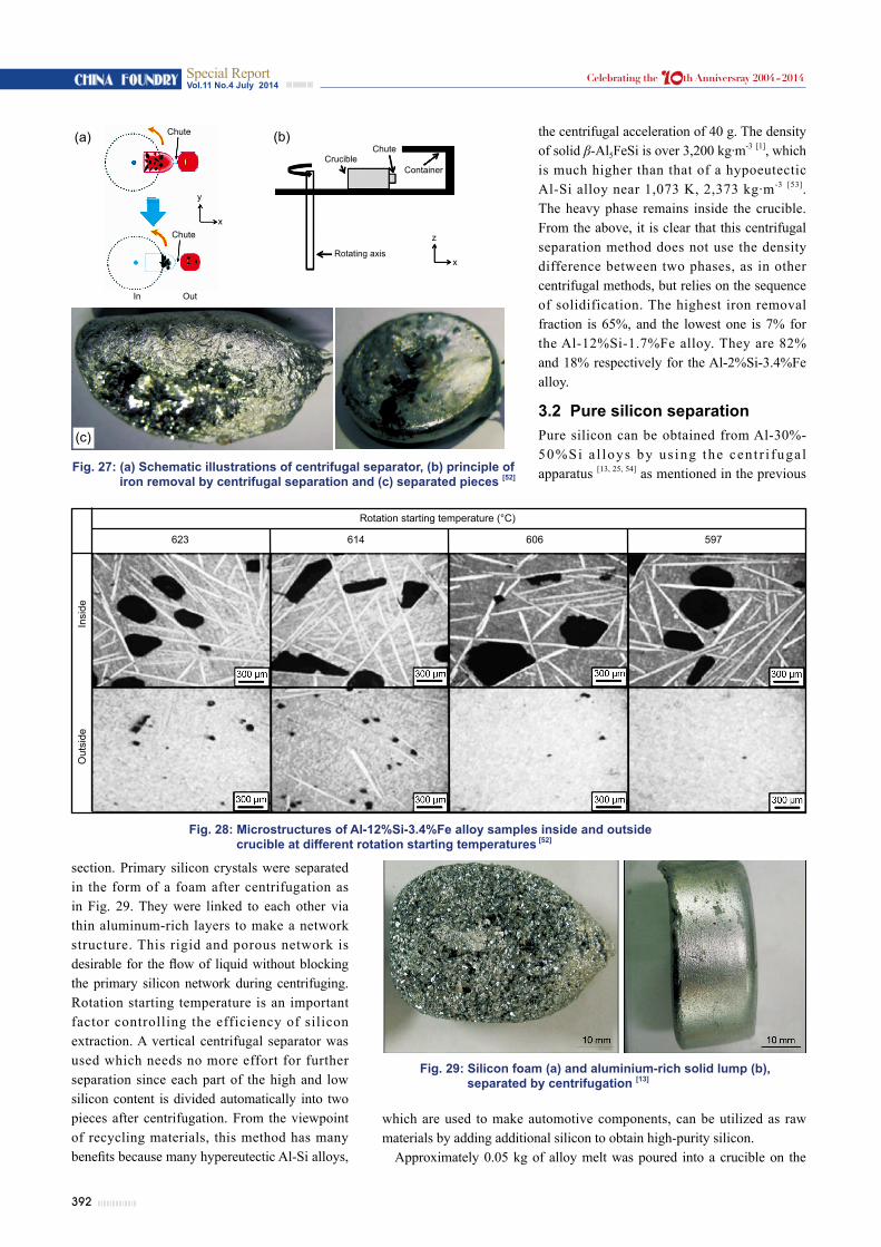
Kim et al. [52] introduced a novel centrifuging method to separate iron-rich intermetallic compounds during solidification. It uses not only the density difference between two phases as in the other centrifugal methods, but also uses the order of solidification in Al-Si-Fe alloys. Their method is similar to Singleton and Robinson’s method in making a network of the primary phase. However an attractive feature of their method is that it needs no more effort to separate further since each part of high and low iron content is divided automatically into two pieces after centrifuging. Figure 27 shows the schematic illustrations of the centrifugal separator, the principle of iron removal by centrifugal separation and the separated pieces. Figure 28 shows the microstructures of Al-12%Si-3.4%Fe alloy samples inside and outside the crucible at different rotation starting temperatures.
Coarse intermetallic compounds were found in the sample inside the crucible in spite of their higher density, while rather fine intermetallic compounds were found in the sample outside the crucible. Primary intermetallic compounds were linked to each other via an aluminum-rich matrix and formed like a network. Much iron remained in the type of β-Al5FeSi compound inside the crucible and it showed that the iron content could be lowered using sequential solidification. Iron-rich phase could be efficiently removed by centrifuging under
Fig. 24: Centrifuged ring: picture (b) is magnified one of (a) [51]
Vol.11 No.4 July 2014Special ReportCHINA FOUNDRY Celebrating the 10th Anniversray 2004-2014
Fig. 28: Microstructures of Al-12%Si-3.4%Fe alloy samples inside and outside crucible at different rotation starting temperatures [52]
section. Primary silicon crystals were separated in the form of a foam after centrifugation as in Fig. 29. They were linked to each other via thin aluminum-rich layers to make a network structure. This rigid and porous network is desirable for the flow of liquid without blocking the primary silicon network during centrifuging. Rotation starting temperature is an important factor controlling the efficiency of silicon extraction. A vertical centrifugal separator was used which needs no more effort for further separation since each part of the high and low silicon content is divided automatically into two pieces after centrifugation. From the viewpoint of recycling materials, this method has many benefits because many hypereutectic Al-Si alloys,
Fig. 27: (a) Schematic illustrations of centrifugal separator, (b) principle of iron removal by centrifugal separation and (c) separated pieces [52]
Fig. 29: Silicon foam (a) and aluminium-rich solid lump (b), separated by centrifugation [13]
the centrifugal acceleration of 40 g. The density of solid β-Al5FeSi is over 3,200 kg·m-3 [1], which is much higher than that of a hypoeutectic Al-Si alloy near 1,073 K, 2,373 kg·m-3 [53]. The heavy phase remains inside the crucible. From the above, it is clear that this centrifugal separation method does not use the density difference between two phases, as in other centrifugal methods, but relies on the sequence of solidification. The highest iron removal fraction is 65%, and the lowest one is 7% for the Al-12%Si-1.7%Fe alloy. They are 82% and 18% respectively for the Al-2%Si-3.4%Fe alloy.
3.2 Pure silicon separationPure silicon can be obtained from Al-30%-50%Si a l loys by us ing the cen t r i fuga l apparatus [13, 25, 54] as mentioned in the previous
which are used to make automotive components, can be utilized as raw materials by adding additional silicon to obtain high-purity silicon.
Approximately 0.05 kg of alloy melt was poured into a crucible on the
In Out
Chute
Chute
y
x
ChuteCrucible
Rotating axis
z
x
Container
(a) (b)
(c)
Rotation starting temperature (°C)
623 614 606 597
Out
side
I
nsid
e
393
Vol.11 No.4 July 2014Special Report CHINA FOUNDRYCelebrating the 10th Anniversray 2004-2014
centrifuging apparatus. Before rotating, the alloy melt was allowed to crystallize the primary silicon to some extent after being poured into the crucible which was made of clay-bonded fused silica. The waiting time after pouring the melt into the crucible was determined based on the solid fraction calculated from the Al-Si binary alloy phase diagram. The gravitational acceleration was 50 g. As the Al-rich phase was pushed outside the crucible, most of the coarse primary silicon crystals remained inside the crucible. The surface of the silicon foam was covered with a thin aluminum layer.
Figure 30 shows the internal images of pieces S1 to S4 at vertical and longitudinal sections for the Al-30%Si sample. The white, gray and black parts correspond to aluminum-rich phases, silicon flakes and empty space, respectively. The S1 part consists almost entirely of an aluminum-rich phase, the other parts, from S2 to S4, consist of silicon flakes. The cross-sectional area of the crucible begins to narrow rapidly at S1 part, so the unfrozen area which is a path of aluminum-rich phase becomes smaller, and some of primary silicon are stuck here. As a result, the last part of the aluminim-rich phase is piled up at near the outlet and the sample solidifies completely. Pure silicon flakes after acid leaching with aqua regia could be obtained as shown in Fig. 31.
An intensified separation of primary silicon from the hypereutectic Al-Si melt was also investigated using super-gravity [55]. The apparatus, as shown in Fig. 32, is similar to that of Fig. 25, which was used for reducing iron and manganese content. The results indicated that the refined silicon grains were successfully enriched at the bottom of the Al-Si alloy along the direction of super-gravity. Then the refined silicon was collected by aqua regia leaching. Figure 33 shows the effect of gravity coefficient on solidification structures of Al-35%Si alloy at g = 1 and 403. The purity of the collected silicon was analyzed as 99.92%, which was obviously improved compared with the purity of the metallurgical grade silicon of 99.59%, proving the feasibility of this purification method. Furthermore, the mass fraction of boron was reduced from 8.33 to 5.25 ppmw and that of phosphor from 33.65 to 13.50 ppmw.
A third element like tin was also alloyed with silicon to enhance the silicon recovery [56]. MG-Si lumps were crushed, and then the silicon powder (150 to 500 μm) was mixed with analytical purity tin forming a mixture of Sn-12%Si. Figure 34 shows the solvent refining and separation and acid leaching processes to get high purity silicon. The solidified alloy was placed in an alumina filter, and the filter was put into the rotor furnace, heated to
Fig. 31: Silicon flakes after acid leaching [13]
Fig. 30: Engineering compacted tomography images of (a) a silicon foam for Al-30%Si sample: vertical (part S1 to S4) and (b) longitudinal sections [13].
Fig. 32: Schematic diagram of experimental centrifugal apparatus [55]
Gas outlettube
CounterweightCentrifugal axis
Conductivesliping Covering
slagInsulating layer
Resistance coil
SpecimenTemperaturecontroller
Graphite crucibleConductiveslip ring Themocouple Gas inlet tube
Fig. 33: Effect of gravity coefficient on solidification structures of Al-35%Si alloy: (a) g = 1; (b) g = 403 [55]
Supe
r gra
vity
(a) (b)
394
Vol.11 No.4 July 2014Special ReportCHINA FOUNDRY Celebrating the 10th Anniversray 2004-2014
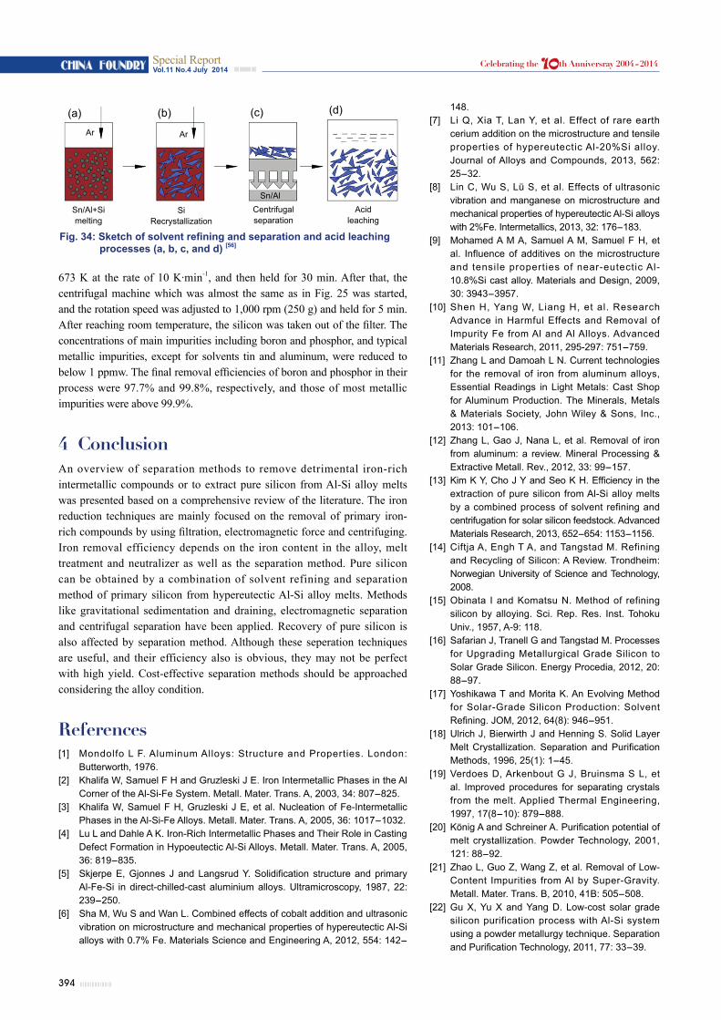
673 K at the rate of 10 K·min-1, and then held for 30 min. After that, the centrifugal machine which was almost the same as in Fig. 25 was started, and the rotation speed was adjusted to 1,000 rpm (250 g) and held for 5 min. After reaching room temperature, the silicon was taken out of the filter. The concentrations of main impurities including boron and phosphor, and typical metallic impurities, except for solvents tin and aluminum, were reduced to below 1 ppmw. The final removal efficiencies of boron and phosphor in their process were 97.7% and 99.8%, respectively, and those of most metallic impurities were above 99.9%.
4 ConclusionAn overview of separation methods to remove detrimental iron-rich intermetallic compounds or to extract pure silicon from Al-Si alloy melts was presented based on a comprehensive review of the literature. The iron reduction techniques are mainly focused on the removal of primary iron-rich compounds by using filtration, electromagnetic force and centrifuging. Iron removal efficiency depends on the iron content in the alloy, melt treatment and neutralizer as well as the separation method. Pure silicon can be obtained by a combination of solvent refining and separation method of primary silicon from hypereutectic Al-Si alloy melts. Methods like gravitational sedimentation and draining, electromagnetic separation and centrifugal separation have been applied. Recovery of pure silicon is also affected by separation method. Although these seperation techniques are useful, and their efficiency also is obvious, they may not be perfect with high yield. Cost-effective separation methods should be approached considering the alloy condition.
References[1] Mondolfo L F. Aluminum Alloys: Structure and Properties. London:
Butterworth, 1976.[2] Khalifa W, Samuel F H and Gruzleski J E. Iron Intermetallic Phases in the Al
Corner of the Al-Si-Fe System. Metall. Mater. Trans. A, 2003, 34: 807-825.[3] Khalifa W, Samuel F H, Gruzleski J E, et al. Nucleation of Fe-Intermetallic
Phases in the Al-Si-Fe Alloys. Metall. Mater. Trans. A, 2005, 36: 1017-1032.[4] Lu L and Dahle A K. Iron-Rich Intermetallic Phases and Their Role in Casting
Defect Formation in Hypoeutectic Al-Si Alloys. Metall. Mater. Trans. A, 2005, 36: 819-835.
[5] Skjerpe E, Gjonnes J and Langsrud Y. Solidification structure and primary Al-Fe-Si in direct-chilled-cast aluminium alloys. Ultramicroscopy, 1987, 22: 239-250.
[6] Sha M, Wu S and Wan L. Combined effects of cobalt addition and ultrasonic vibration on microstructure and mechanical properties of hypereutectic Al-Si alloys with 0.7% Fe. Materials Science and Engineering A, 2012, 554: 142-
Fig. 34: Sketch of solvent refining and separation and acid leaching processes (a, b, c, and d) [56]
148.[7] Li Q, Xia T, Lan Y, et al. Effect of rare earth
cerium addition on the microstructure and tensile properties of hypereutectic Al-20%Si alloy. Journal of Alloys and Compounds, 2013, 562: 25-32.
[8] Lin C, Wu S, Lü S, et al. Effects of ultrasonic vibration and manganese on microstructure and mechanical properties of hypereutectic Al-Si alloys with 2%Fe. Intermetallics, 2013, 32: 176-183.
[9] Mohamed A M A, Samuel A M, Samuel F H, et al. Influence of additives on the microstructure and tensile properties of near-eutectic Al-10.8%Si cast alloy. Materials and Design, 2009, 30: 3943-3957.
[10] Shen H, Yang W, Liang H, et al. Research Advance in Harmful Effects and Removal of Impurity Fe from Al and Al Alloys. Advanced Materials Research, 2011, 295-297: 751-759.
[11] Zhang L and Damoah L N. Current technologies for the removal of iron from aluminum alloys, Essential Readings in Light Metals: Cast Shop for Aluminum Production. The Minerals, Metals & Materials Society, John Wiley & Sons, Inc., 2013: 101-106.
[12] Zhang L, Gao J, Nana L, et al. Removal of iron from aluminum: a review. Mineral Processing & Extractive Metall. Rev., 2012, 33: 99-157.
[13] Kim K Y, Cho J Y and Seo K H. Efficiency in the extraction of pure silicon from Al-Si alloy melts by a combined process of solvent refining and centrifugation for solar silicon feedstock. Advanced Materials Research, 2013, 652-654: 1153-1156.
[14] Ciftja A, Engh T A, and Tangstad M. Refining and Recycling of Silicon: A Review. Trondheim: Norwegian University of Science and Technology, 2008.
[15] Obinata I and Komatsu N. Method of refining silicon by alloying. Sci. Rep. Res. Inst. Tohoku Univ., 1957, A-9: 118.
[16] Safarian J, Tranell G and Tangstad M. Processes for Upgrading Metallurgical Grade Silicon to Solar Grade Silicon. Energy Procedia, 2012, 20: 88-97.
[17] Yoshikawa T and Morita K. An Evolving Method for Solar-Grade Silicon Production: Solvent Refining. JOM, 2012, 64(8): 946-951.
[18] Ulrich J, Bierwirth J and Henning S. Solid Layer Melt Crystallization. Separation and Purification Methods, 1996, 25(1): 1-45.
[19] Verdoes D, Arkenbout G J, Bruinsma S L, et al. Improved procedures for separating crystals from the melt. Applied Thermal Engineering, 1997, 17(8-10): 879-888.
[20] König A and Schreiner A. Purification potential of melt crystallization. Powder Technology, 2001, 121: 88-92.
[21] Zhao L, Guo Z, Wang Z, et al. Removal of Low-Content Impurities from Al by Super-Gravity. Metall. Mater. Trans. B, 2010, 41B: 505-508.
[22] Gu X, Yu X and Yang D. Low-cost solar grade silicon purification process with Al-Si system using a powder metallurgy technique. Separation and Purification Technology, 2011, 77: 33-39.
Sn/Al+Simelting
Si Recrystallization
Centrifugalseparation
Acidleaching
Ar Ar
Sn/Al
(a) (b) (c) (d)
395
Vol.11 No.4 July 2014Special Report CHINA FOUNDRYCelebrating the 10th Anniversray 2004-2014
[23] Gao J W, Shu D, Wang J, et al. Elimination of Fe in Al-Si cast alloy scrap by electromagnetic filtration. Scr. Mater., 2007, 57: 197-200.
[24] Xu Z, Li T and Zhou Y. Elimination of Fe in Al-Si cast alloy scrap by electromagnetic filtration. Journal of Materials Science, 2003, 38: 4557-4565.
[25] Cho J Y, Kang B H, and Kim K Y. Extraction of Pure Si from an Al-Si Alloy Melt during Solidification by Centrifugal Force. Kor. J. Met. Mater, 2011, 49(11): 874-881.
[26] Johnston M, Khajavi L T, Li M, et al. High temperature refining of metallurgical grade silicon: a review. JOM, 2012, 64: 935-945.
[27] Cho J Y and Kim K Y. Structure and Compressive Strength of Silicon Open-Cell Foam Obtained by a Centrifugal Separation Method. Met. Mater. Int., 2013, 19(2): 361-365.
[28] Yoshikawa T and Morita K. Refining of Si by the solidification of Si-Al melt with electromagnetic force. ISIJ International, 2005, 45: 967-971.
[29] Shabestari S G and Gruzleski J E. Gravity Segregation of Complex Intermetallic Compounds in Liquid Aluminum-Silicon Alloys. Metallurgical and Materials Transactions A, 1995, 26A: 1995-999.
[30] Conlsont J M, Richardson J F, Backgurst J R, et al. Chemical Engineering. Pergamon Press: Elmsford, NY, 1991, 2: 95-131.
[31] Cao X and Campbell J. The Solidification Characteristics of Fe-Rich Intermetallics in Al-11.5Si-0.4Mg Cast Alloys. Metall. Mater. Trans. A, 2004, 35A: 1425-1435.
[32] Cao X, Saunders N and Campbell J. Effect of iron and manganese contents on convection-free precipitation and sedimentation of primary α-Al(FeMn)Si phase in liquid Al-11.5Si-0.4Mg alloy. Journal of Materials Science, 2004, 39: 2303-2314.
[33] Cao X and Campbe l l J . E f fec t o f p rec ip i ta t ion and sedimentation of primary α-Fe phase on liquid metal quality of cast Al-11.1Si-0.4Mg alloy. International Journal of Cast Metals Research, 2004, 17(11): 2303-2314.
[34] Cao X and Campbell J. Morphology of α-Al5FeSi Phase in Al-Si Cast Alloys. Materials Transactions, 2006, 47(5): 1303-1312.
[35] Shabestari S G, Keshavarz M, and Hejazi M M. Effect of strontium on the kinetics of formation and segregation of intermetallic compounds in A380 aluminum alloy. Journal of Alloys and Compounds, 2009, 477: 892-899.
[36] Ashtari P, Tetley-Gerard K and Sadayappan K. Removal of iron from recycled aluminium alloys. Canadian Metallurgical Quarterly, 2012, 51(1): 75.
[37] Moraes H L, Oliveira J R, Espinosa D C R, et al. Removal of Iron from Molten Recycled Aluminum through Intermediate Phase Filtration. Materials Transactions, 2006, 47(7): 1731-1736.
[38] Gumaste J L, Mohanty B C, Galgali R K, et al. Solvent refining of metallurgical grade silicon. Solar Energy Materials, 1987, 16: 289-296.
[39] Criado A J, Martinez J A and Calabres R. Growth of eutectic silicon from primary silicon crystals in aluminium-silicon alloys. Scripta Materialia, 1997, 36(1): 47-54.
[40] Dawless R K, Troup R L, Meier D L, et al. Production of extreme-purity aluminum and silicon by fractional crystallization processing. Journal of Crystal Growth, 1988, 89: 68-74.
[41] Sollman D. Pure and simple. Photon International, 2009: 110-115.
[42] Dewan M A, Rhamdhani M A, Mitchell J B, et al. Control and removal of impurities from Al melts. Materials Science Forum, 2011, 693: 149-160.
[43] Li T, Xu Z, Sun B, et al. Electromagnetic separation of primary iron rich phases from aluminum-silicon melt. Trans. Nonferrous Met. Soc. China, 2013, 13: 121-125.
[44] Xu Z, Li T and Zhou Y. Elimination of Fe in Al-Si cast alloy scrap by electromagnetic filtration. Journal of Materials Science, 2003, 38: 4557-4565.
[45] Lee G-C, Kim M-G, Park J-P, et al. Iron Removal in Aluminum Melts Containing Scrap by Electromagnetic Stirring. Materials Science Forum, 2010, 638-642: 267-272.
[46] Yoshikawa T and Morita K. Refining of silicon during its solidification from a Si-Al melt. Journal of Crystal Growth, 2009, 311: 776-779.
[47] Yoshikawa T and Morita K. Continuous Solidification of Si from Si-Al Melt under the Induction Heating. ISIJ International, 2007, 47(4): 582-584.
[48] Li J, Liu Y, Tan Y, et al. Effect of tin addition on primary silicon recovery in Si-Al melt during solidification refining of silicon. Journal of Crystal Growth, 2013, 371: 1-6.
[49] Singleton O R and Robinson G C J. Refining aluminum-silicon alloys by centrifuging. Journal of the Institute of Metals, 1971, 99: 155-159.
[50] Matsubara H, Izawa N and Nakanishi M. Macro-segregation in Al-11%Si alloy containing 2% Fe solidified under centrifugal force. JLIM, 1998, 48: 93-97
[51] Kräutlein C and Friedrich B. Removal of intermetal l ic precipitates from Al melts by immersed centrifugation technology. In: Proceedings of European Metall. Conf., 2005: 1593-1573.
[52] Kim S W, Im U H, Cha H C, et al. Removal of primary iron rich phase from aluminum-silicon melt by centrifugal separation. China Foundry, 2013, 10: 112-117.
[53] Magnusson T and Arnberg L. Density and Solidification Shrinkage of Hypoeutectic Aluminum-Silicon Alloys. Metall. Mater. Trans. A., 2001, 32A: 2605-2613.
[54] Cho J Y, Kang B H and Kim K Y. Centrifugal separation of primary silicon during solidification in Al-Si alloy for solar silicon feedstock. Materials Science Forum, 2012, 706-709: 819-822.
[55] Li J, Guo Z, Tang H, et al. Si purification by solidification of Al-Si melt with super gravity. Trans. Nonferrous Met. Soc. China, 2012, 22: 958-963.
[56] Hu L, Wang Z, Gong X, et al. Impurities Removal from Metallurgical-Grade Silicon by Combined Sn-Si and Al-Si Refining Processes. Metall. Mater. Trans. B, 2013, 44B: 828-836.
This research was financially supported by the Basic Science Research Program through the National Research Foundation of Korea (NRF), the Ministry of Education, Science and Technology of Korea (No. 2012R1A1A2007476), and was also supported by the Korea University of Technology and Education.