Separation of specular reflection and diffraction images in Kirchhoff depth migration Faruq E Akbar and Jun Ma, SEIMAX Technologies, LP Summary Seismic diffractions may occur from faults, fractures, rough surfaces, and buried channels. In depth migrated volumes these relatively weak arrivals, as discussed by Hilterman, (1975) are often masked by stronger specular reflections. We propose a new method to separate specular reflections from diffractions in Kirchhoff depth migration using local angle information from ray tracing and dip picking from the stacked depth image. We derive a formula for the Fresnel zone that is a function of local ray angles to differentiate between seismic diffractions and specular reflections. Our method provides a cost effective alternative to currently used methods for separation of specular reflections from diffractions. Introduction Seismic data primarily contains reflection, noise, and diffraction information. The depth imaging process maps these arrivals in the correct location by treating each point as a potential diffractor. However the end product reveals mostly specular reflections because its amplitude and continuity masks the potential diffractions. Several authors pointed out the usefulness of diffractions. Harlan et al (1984) used the lateral coherency and statistical predictability of reflection events and noise to separate diffractions. Then they utilized diffractions to invert for velocity. Diffraction imaging based on summation of coherent diffracted events in common-offset and common- diffraction-point domain are proposed by Landa et al. (1987), and Landa and Keydar (1998) respectively. Kozlov et al. (2004) showed the importance of imaging diffractions. Their methodology was based on common scattering angle migration with a weighting function in migration operators to deemphasize the specular part of migration. The technique successfully mapped several faults and layers of interest. Klokov and Fomel (2012) proposed another approach to separate diffractions from reflections in the dip-angle domain instead of the scattering-angle domain. They used Radon transformation and analytic shape difference for separation and velocity inversion. Recently, Sun et al. (2015) showed a method for diffraction imaging where they proposed dip picking in the dip angle domain. In this paper, instead of dip-angle domain picking due to computation cost concern, we propose dip picking from a stacked section. Our method uses local angle from source and receiver ray to calculate the resultant angle from specular reflectors. Since the resultant angle from a specular reflector is normal to the reflector itself, given the Fresnel zone, we can separate the reflections from diffractions. This method should serve as a cost effective routine process in depth migration. Method We will describe the method in context of Kirchhoff migration in the depth domain valid for both 2D and 3D. We will describe reflection as waves arriving from specular reflectors within the Fresnel zone. All other arrivals are counted as diffractions. Figure 1 shows a source at location S. The reflection from the dipping reflector arrives at receiver R only when the resultant of rays SP and RP is normal to the dip of reflector at point P. Given a diffractor at any location, all arrivals to all receivers are diffractions. Figure 1: Reflection vs diffraction. Reflection occurs when source (S) ray reflects at location P and arrives at receiver R only when the resultant of source and receiver rays is normal to the reflector at point P. Diffraction occurs when the source ray reaches a diffractor and diffraction arrives at all receiver locations. For the first step we calculate the dip of reflectors (Claerbout 1992, Fomel 2002) from a depth migrated volume. For the second step we use ray tracing based on Cerveny (2001) to compute local ray angles for a 3D velocity model. During Kirchhoff migration, for each image point and for each source-receiver pair, the resultant of source-receiver ray angles is computed. The next step is to match the dip of reflectors with the resultant angle and stack within the Fresnel zone for a reflection-only image. All other arrivals where there is no reflector or beyond the Fresnel zone are stacked to produce the diffraction-only volume. The addition of these reflections and diffractions will produce a typical depth image. The Fresnel zone plays an important role in the stacking for both reflection and diffraction images. We derive a ray
Transcript
Separation of specular reflection and diffraction images in Kirchhoff depth migration Faruq E Akbar and Jun Ma, SEIMAX Technologies, LP Summary Seismic diffractions may occur from faults, fractures, rough surfaces, and buried channels. In depth migrated volumes these relatively weak arrivals, as discussed by Hilterman, (1975) are often masked by stronger specular reflections. We propose a new method to separate specular reflections from diffractions in Kirchhoff depth migration using local angle information from ray tracing and dip picking from the stacked depth image. We derive a formula for the Fresnel zone that is a function of local ray angles to differentiate between seismic diffractions and specular reflections. Our method provides a cost effective alternative to currently used methods for separation of specular reflections from diffractions. Introduction Seismic data primarily contains reflection, noise, and diffraction information. The depth imaging process maps these arrivals in the correct location by treating each point as a potential diffractor. However the end product reveals mostly specular reflections because its amplitude and continuity masks the potential diffractions. Several authors pointed out the usefulness of diffractions. Harlan et al (1984) used the lateral coherency and statistical predictability of reflection events and noise to separate diffractions. Then they utilized diffractions to invert for velocity. Diffraction imaging based on summation of coherent diffracted events in common-offset and common-diffraction-point domain are proposed by Landa et al. (1987), and Landa and Keydar (1998) respectively. Kozlov et al. (2004) showed the importance of imaging diffractions. Their methodology was based on common scattering angle migration with a weighting function in migration operators to deemphasize the specular part of migration. The technique successfully mapped several faults and layers of interest. Klokov and Fomel (2012) proposed another approach to separate diffractions from reflections in the dip-angle domain instead of the scattering-angle domain. They used Radon transformation and analytic shape difference for separation and velocity inversion. Recently, Sun et al. (2015) showed a method for diffraction imaging where they proposed dip picking in the dip angle domain. In this paper, instead of dip-angle domain picking due to computation cost concern, we propose dip picking from a stacked section. Our method uses local angle from source and receiver ray to calculate the resultant angle from specular reflectors. Since the resultant angle from a specular reflector is normal to the reflector itself, given the Fresnel zone, we can separate the
reflections from diffractions. This method should serve as a cost effective routine process in depth migration. Method We will describe the method in context of Kirchhoff migration in the depth domain valid for both 2D and 3D. We will describe reflection as waves arriving from specular reflectors within the Fresnel zone. All other arrivals are counted as diffractions. Figure 1 shows a source at location S. The reflection from the dipping reflector arrives at receiver R only when the resultant of rays SP and RP is normal to the dip of reflector at point P. Given a diffractor at any location, all arrivals to all receivers are diffractions.
Figure 1: Reflection vs diffraction. Reflection occurs when source (S) ray reflects at location P and arrives at receiver R only when the resultant of source and receiver rays is normal to the reflector at point P. Diffraction occurs when the source ray reaches a diffractor and diffraction arrives at all receiver locations. For the first step we calculate the dip of reflectors (Claerbout 1992, Fomel 2002) from a depth migrated volume. For the second step we use ray tracing based on Cerveny (2001) to compute local ray angles for a 3D velocity model. During Kirchhoff migration, for each image point and for each source-receiver pair, the resultant of source-receiver ray angles is computed. The next step is to match the dip of reflectors with the resultant angle and stack within the Fresnel zone for a reflection-only image. All other arrivals where there is no reflector or beyond the Fresnel zone are stacked to produce the diffraction-only volume. The addition of these reflections and diffractions will produce a typical depth image. The Fresnel zone plays an important role in the stacking for both reflection and diffraction images. We derive a ray
Reflection and diffraction imaging
travel time based Fresnel zone formula that is a function of local ray angle and dip of a reflector. The derivation shown here is based on straight rays but should be valid for some inhomogeneity, as discussed by Sheriff (1980). Figure 2a shows a reflection point P of a dipping layer. The dip of the reflector is ∅. Note that the vertical angle of the zero-offset ray PR at this reflection point is also ∅. In fact, the resultant of a source-receiver pair rays with true reflection will be normal to the reflector at this point P and thus have a vertical angle of ∅. Let us consider a travel time associated to ray PR is T1. Let us also assume the vertical travel time from point P is T0. Consider another ray PR1 in the vicinity of PR with travel time T2 and vertical angle (∅ + 𝜃). From Figure 2a, the Fresnel zone criteria is satisfied if maximum T2 = T1+1/(4f), where f is frequency of input trace, as discussed by Sheriff (1980).
Figure 2a: Local dip ∅ of the reflector is equal to the zero offset ray angle which coinsides with the resultant direction of a non-zero offset source-receiver pair. Let us consider T1 is the zero offset travel time. Another ray with vertical angle (∅ + 𝜃) is considered with a travel time T2. The vertical travel time from the reflection point is T0. From Figure 2a:
cos∅ =𝑇0𝑇1
cos(𝜃 + ∅) =𝑇0𝑇2
=𝑇0
𝑇1 + 14𝑓
Equating T0 of above two equations:
cos 𝜃 + ∅ =𝑇1 𝑐𝑜𝑠∅
𝑇1 + 14𝑓
𝜃 = cos!!𝑇1𝑐𝑜𝑠∅
𝑇1 + 14𝑓
− ∅
In our implementation, when the difference of reflector dip and the resultant of source-receiver ray angle are within the value of 𝜃, then the stack is considered as reflection image. The rest of the stack is considered as diffraction image. To calculate 𝜃 we have used the lowest available frequency (5 Hz) for 𝑓 and the average of source-receiver travel time for T1. Note that as expected, 𝜃 decreases with the increase of time (T1) or increase of dip of reflector ∅. Figure 2b shows the plot of the Fresnel angle (𝜃) with respect to travel time for various reflector dips. It can be observed in this figure that the Fresnel angle decreases with increase of travel time and reflector dip respectively. Note that the increasing travel time and dip of the reflectors reduce the resolve of diffraction imaging. We have used a cutoff of 2 degrees for Fresnel zone angle. We also used a mild taper at the border of the Fresnel zone.
Figure 2b: Fresnel angle plot with increase of travel time, for various reflector dips. Examples Followings are two synthetic and one real data examples to show the accuracy of our method. We applied dip field picked from depth migrated stack and the angle domain Fresnel zone derived here to separate reflection and diffraction images. The first example is based on a simple velocity model of a single interface shown in Figure 3a. The velocities above and below the interface are 2 km/sec and 2.5 km/sec respectively. The depth and width of the model are 3.5 and 7.5 km respectively. We inserted two diffractors indicated by arrows in the figure. Synthetic data are generated by the finite difference method. Figure 3b shows the diffraction image where diffractors are correctly imaged. Note that the sharp corners of the interface are also mapped as diffractors. Additional events are mapped from outside of the Fresnel zone and edges of the model. Figure 3c shows the reflection image of the same model. Note that the diffractors are absent from the reflection image. The summation of diffraction and reflection image is shown in Figure 3d.
Reflection and diffraction imaging
Figure 3a: Simple velocity model with two diffractors shown by arrows.
Figure 3b: Diffraction imaging.
Figure 3c: Reflection-only image
Figure 3d: Reflection plus diffraction image. The second example is based on left side of Sigsbee dataset where diffractions and faults are present. Figure 4a shows a stacked depth image. Figure 4b shows picked dips from a depth migrated section. In this figure white colors represent near-zero dips, and red and blue represent positive and
negative dips. Figure 4c shows the diffraction image. Diffractions on the left side of the model are correctly imaged. Note that the faults indicated by arrows are also prominent in this image. Figure 4d shows the reflection-only image.
Figure 4a: Sigsbee stacked depth section.
Figure 4b: Sigsbee model; dips are picked from stacked depth section.
Figure 4c: Sigsbee model; diffraction image. Arrows indicate the faults and diffractions.
Reflection and diffraction imaging
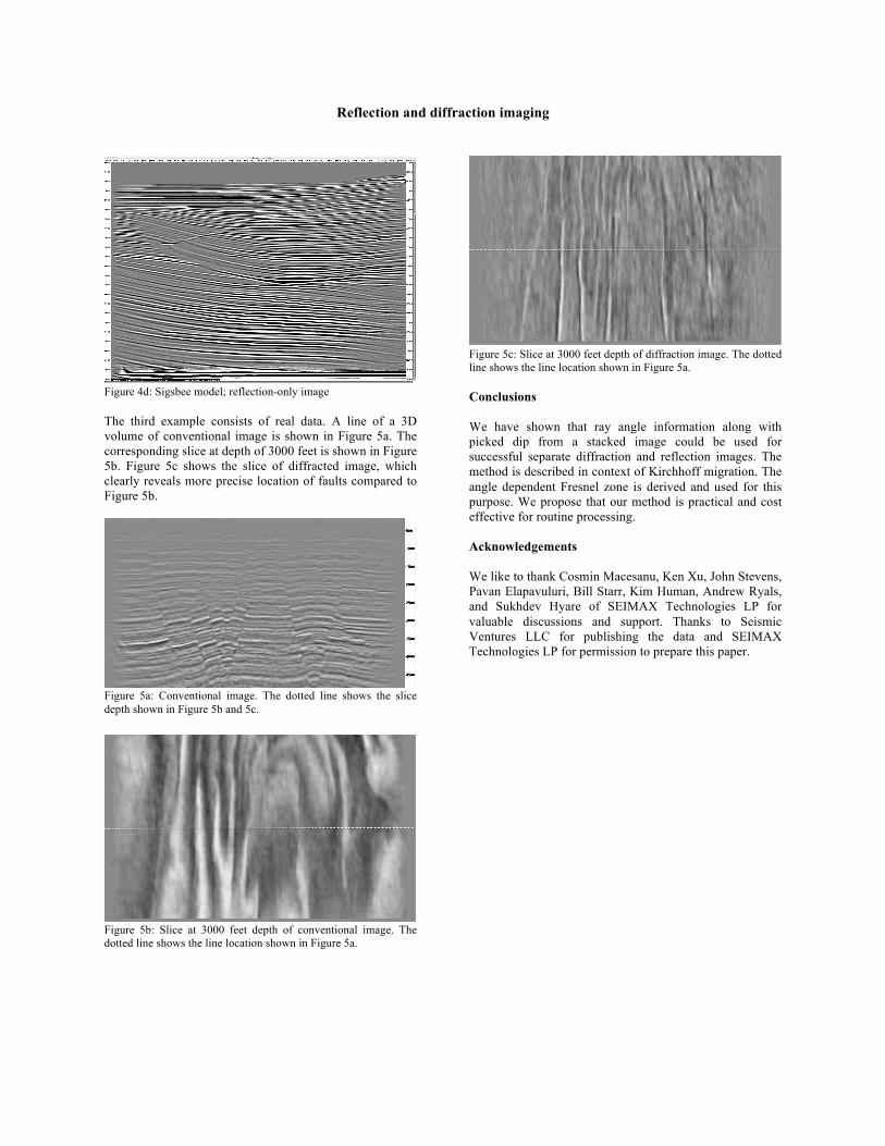
Figure 4d: Sigsbee model; reflection-only image The third example consists of real data. A line of a 3D volume of conventional image is shown in Figure 5a. The corresponding slice at depth of 3000 feet is shown in Figure 5b. Figure 5c shows the slice of diffracted image, which clearly reveals more precise location of faults compared to Figure 5b.
Figure 5a: Conventional image. The dotted line shows the slice depth shown in Figure 5b and 5c.
Figure 5b: Slice at 3000 feet depth of conventional image. The dotted line shows the line location shown in Figure 5a.
Figure 5c: Slice at 3000 feet depth of diffraction image. The dotted line shows the line location shown in Figure 5a. Conclusions We have shown that ray angle information along with picked dip from a stacked image could be used for successful separate diffraction and reflection images. The method is described in context of Kirchhoff migration. The angle dependent Fresnel zone is derived and used for this purpose. We propose that our method is practical and cost effective for routine processing. Acknowledgements We like to thank Cosmin Macesanu, Ken Xu, John Stevens, Pavan Elapavuluri, Bill Starr, Kim Human, Andrew Ryals, and Sukhdev Hyare of SEIMAX Technologies LP for valuable discussions and support. Thanks to Seismic Ventures LLC for publishing the data and SEIMAX Technologies LP for permission to prepare this paper.
Reflection and diffraction imaging
References Cerveny, V., 2001, Seismic ray theory: Cambridge University Press, Cambridge. Claerbout, J. F., 1992, Earth soundings analysis: Processing versus inversion: Blackwell Scientific Publications, Inc. Fomel. S., 2002, Application of plane-wave destruction filters: Geophysics, 67, 1946-1960. Harlan, W. S., j. F. Claerbout, F. Rocca, 1984, Signal/noise separation and velocity estimation: Geophysics, 49, 1869-1880. Hilterman, F., 1975, Amplitudes of seismic waves – A quick look: Geophysics, 40, 745-762. Klokov, A. and S. Fomel, Separation and imaging of seismic diffractions using migrated dip-angle gathers: Geophysics, 77, S131-S143. Kozlov, E., N. Barasky, E. Korolev, A. Antonenko, and E. Koshchuk, Imaging scattring objects masked by specular reflections: SEG Technical Program Expanded Abstracts, 2004, 1131-1134. Landa, E., V. Shtivelman, and B. Gelchinsky, 1987, A method for detection of diffracted waves on common-offset sections: Geophysical Prospecting, 35, 359-373. Landa, E. and S, Keydar, 1998, Seismic monitoring of diffracted images for detection of local heterogeneities: Geophysics, 63, 1093-1100.