This is a repository copy of Sequential combustion in steam methane reformers for hydrogen and power production with CCUS in decarbonized industrial clusters . White Rose Research Online URL for this paper: http://eprints.whiterose.ac.uk/165185/ Version: Published Version Article: Herraiz, L., Lucquiaud, M., Chalmers, H. et al. (1 more author) (2020) Sequential combustion in steam methane reformers for hydrogen and power production with CCUS in decarbonized industrial clusters. Frontiers in Energy Research, 8. 180. https://doi.org/10.3389/fenrg.2020.00180 [email protected]https://eprints.whiterose.ac.uk/ Reuse This article is distributed under the terms of the Creative Commons Attribution (CC BY) licence. This licence allows you to distribute, remix, tweak, and build upon the work, even commercially, as long as you credit the authors for the original work. More information and the full terms of the licence here: https://creativecommons.org/licenses/ Takedown If you consider content in White Rose Research Online to be in breach of UK law, please notify us by emailing [email protected] including the URL of the record and the reason for the withdrawal request.
Transcript
This is a repository copy of Sequential combustion in steam methane reformers for hydrogen and power production with CCUS in decarbonized industrial clusters.
White Rose Research Online URL for this paper:http://eprints.whiterose.ac.uk/165185/
Version: Published Version
Article:
Herraiz, L., Lucquiaud, M., Chalmers, H. et al. (1 more author) (2020) Sequential combustion in steam methane reformers for hydrogen and power production with CCUS indecarbonized industrial clusters. Frontiers in Energy Research, 8. 180.
This article is distributed under the terms of the Creative Commons Attribution (CC BY) licence. This licence allows you to distribute, remix, tweak, and build upon the work, even commercially, as long as you credit the authors for the original work. More information and the full terms of the licence here: https://creativecommons.org/licenses/
Takedown
If you consider content in White Rose Research Online to be in breach of UK law, please notify us by emailing [email protected] including the URL of the record and the reason for the withdrawal request.
Sequential Combustion in SteamMethane Reformers for Hydrogenand Power Production With CCUS inDecarbonized Industrial ClustersLaura Herraiz1* , Mathieu Lucquiaud1, Hannah Chalmers1 and Jon Gibbins2
1 School of Engineering, The University of Edinburgh, Edinburgh, United Kingdom, 2 Department of Mechanical Engineering,
The University of Sheffield, Sheffield, United Kingdom
In future energy supply systems, hydrogen and electricity may be generated in
decarbonized industrial clusters using a common infrastructure for natural gas supply,
electricity grid and transport and geological storage of CO2. The novel contribution of
this article consists of using sequential combustion in a steam methane reforming (SMR)
hydrogen plant to allow for capital and operating cost reduction by using a single post-
combustion carbon capture system for both the hydrogen process and the combined
cycle gas turbine (CCGT) power plant, plus appropriate integration for this new
equipment combination. The concept would be widely applied to any post-combustion
CO2 capture process. A newly developed, rigorous, gPROMs model of two hydrogen
production technologies, covering a wide range of hydrogen production capacities,
thermodynamically integrated with commercially available gas turbine engines quantifies
the step change in thermal efficiency and hydrogen production efficiency. It includes a
generic post-combustion capture technology – a conventional 30%wt MEA process -
to quantify the reduction in size of CO2 absorber columns, the most capital intensive
part of solvent-based capture systems. For a conventional SMR located downstream
of an H-class gas turbine engine, followed by a three-pressure level HRSG and a
capture plant with two absorbers, the integrated system produces ca. 696,400 Nm3/h
of H2 with a net power output of 651 MWe at a net thermal efficiency of 38.9%LHV.
This corresponds to 34 MWe of additional power, increasing efficiency by 4.9% points,
and makes one absorber redundant compared to the equivalent non-integrated system
producing the same volume of H2. For a dedicated gas heated reformer (GHR) located
downstream of an aeroderivative gas turbine engine, followed by a two-pressure level
HRSG and a capture plant with one absorber, the integrated system produces ca.
80,750 Nm3/h of H2 with a net power output of 73 MWe and a net thermal efficiency of
54.7%LHV. This corresponds to 13 MWe of additional power output, increasing efficiency
by 13.5% points and also makes one absorber redundant. The article also presents new
insights for the design and operation of reformers integrated with gas turbines and with
Herraiz et al. Sequential Combustion in Steam Methane Reformers
INTRODUCTION
Electricity and hydrogen are two low-carbon energy vectorsexpected to play key roles in a zero carbon economy, for exampleto decarbonize power, buildings (heating and cooling), transportand industry sectors. In future energy supply systems there willbe a number of examples of both vectors being generated fromnatural gas at the same location, where a common infrastructureis available for natural gas supply, electricity grid connectionand transport and geological storage of CO2 in carbon capture,utilization and storage (CCUS) industrial clusters (BEIS, 2018).
The possibility of producing hydrogen by a low-carbon routeand storing it at scale makes it a potentially valuable complementin the long-term decarbonization of parts of the energy systemwhere electrification is not feasible and/or more expensive.Besides being a fuel or raw material for some energy intensiveindustries, low-carbon hydrogen can replace natural gas forspace heating in buildings, industrial processes and back-uppower generation and be used as a fuel in heavy transport.Hydrogen distribution networks are also anticipated, providedthat sufficient volumes of hydrogen can be produced at acompetitive price (Committee on Climate Change [CCC], 2018).
Natural gas reforming with carbon capture and storage (CCS)is expected to be a cost-effective option for industrial scaleproduction of low-carbon hydrogen and can therefore help laythe foundation for much higher use of hydrogen across thewhole economy (Committee on Climate Change [CCC], 2018).Currently steam reforming of natural gas or light hydrocarbonsat an appropriate temperature and pressure in the presence of asuitable metal-based catalyst is the leading source of hydrogenused in petrochemical and petroleum refining applications, yetit has high emissions of carbon dioxide, at approximately 7 to10 kgCO2/kgH2 on average. Modern steam methane reformers(SMRs) are widely used for hydrogen production and haveachieved high efficiencies, reducing CO2 emissions down tonearly 10% above the theoretical minimum and further reductionwould only be possible with CCS (IEAGHG, 2017b). In additionto the supply of natural gas as feedstock for synthesis gas andhydrogen production in a SMR, the combustion of naturalgas and the tail gas from hydrogen production and separationprovides the thermal energy for the high temperature heattransfer necessary to drive the endothermic reforming reactionsin the catalytic reactor.
The novel contribution of this article consists of a techniquefor modifying the combustion in an SMR to allow for capitaland operating cost reduction by integration to use a single post-combustion carbon capture (PCC) system for both the SMRand a combined cycle gas turbine (CCGT) power plant, plusappropriate integration for this new equipment combination.
Abbreviations: CCGT, combined cycle gas turbine; CCS, carbon capture andstorage; CCUS, carbon capture, utilization and storage; GHR, gas heated reformer;GT, gas turbine; HP, high pressure; HRSG, heat recovery steam generation; IP,intermediate pressure; LHV , low heating value (MJ kg−1); LP, low pressure; ηH2,hydrogen production efficiency (%); ηth, thermal efficiency (%); m, mass flow rate(kg/s); PCC, post-combustion CO2 capture; PSA, pressure swing adsorption; Q,heat input (MWth); SC, steam cycle; SMR, steam methane reformer; ST, steamturbine; VSA, vacuum swing adsorption; W, power output/power consumption(MWe); WGS, water-gas-shift.
A review of other types of hydrogen production facilities withCCS that are also currently being considered for imminentdeployment is beyond the scope of this study, but the SMRwith PCC in its current form appears competitive (e.g., seeElement Energy Ltd, 2018) and thus a description of possibleimprovements through such integration is topical becauseit could provide additional options for potential industrialusers to consider.
Sharing the CO2 capture process is possible via sequentialcombustion of the SMR fuel gases in the gas turbine exhaust fluegas. The relatively large amount of excess oxygen in the flue gas isused as the source of oxygen for the combustion taking place inthe furnace or combustion chamber of the SMR.
The concept of sequential combustion is critical to thethermodynamic integration of hydrogen production with a gasturbine. Sequential combustion makes use of the excess oxygenin exhaust gases to complete a further stage of combustion; it haspreviously been investigated for coal and gas-fired power plantswith CCS with the objective of maintaining the site power outputand achieving capital cost reduction in the CO2 capture process.
For markets with access to competitive natural gas pricesand the possibility of using the CO2 for enhanced oil recovery(EOR), González Díaz and co-workers (González Díaz et al.,2016) propose the use of sequential supplementary firing (SSF)of natural gas in the heat recovery steam generator (HRSG) ofa CCGT power plant to achieve a ca. 50% reduction in the totalvolume of flue gas generated, which leads to a ca. 15% reductionin capital cost while maintaining the net power output of a CCGTpower plant with CCS. Oxygen levels as low as 1 vol% may bepractically achievable in a CCGT with sequential supplementaryfiring (Kitto and Stultz, 1992).
Sánchez del Río and co-workers (Sanchez del Rio et al., 2017)investigate the use of a gas turbine for re-powering a pulverizedcoal power plant retrofitted with CCS. After recovering heat froma gas turbine exhaust to increase steam production, the exhaustflue gas enters the hot windbox of the pulverized coal boiler,where it replaces secondary air to allow for sequential combustionto take place. In this case, oxygen levels are brought down as lowas practically possible at 3 vol% (Kitto and Stultz, 1992).
Sequential Combustion in SteamMethane Reforming Hydrogen PlantsFor sequential combustion to be applied for the integration ofhydrogen and electricity production with CO2 capture, a fairlyconventional steammethane reformer is located downstream of acommercially available gas turbine engine. The reformer must besized so that the oxidant stream for combustion matches the fluegas volume of an available gas turbine; the former are typicallyspecially made while gas turbines are standard products. The fuelin the SMR is a mixture of the tail gas from hydrogen productionand additional natural gas. The SMR furnace is followed by a heatrecovery steam generator (HRSG), which generates the steamrequired for process use and for electricity generation in thesteam turbine of a combined power cycle.
The cooled flue gas exiting the HRSG enters a post-combustion carbon capture system, where the CO2 generated
Frontiers in Energy Research | www.frontiersin.org 2 August 2020 | Volume 8 | Article 180
Herraiz et al. Sequential Combustion in Steam Methane Reformers
in the SMR furnace, including carbon species in the tail gasfrom hydrogen production, and in the gas turbine combustoris removed. Cost reduction in the capture process is achievedby reducing the number and the size of absorbers due to areduction in the overall volume of the flue gas entering the carboncapture plant, a direct consequence of the use of the GT fluegas for sequential combustion. The integrated configuration canproduce a combination of low-carbon hydrogen and low-carbonelectricity with a reduction in total flue gas flow of approximately30% and a favorable CO2 concentration, i.e., 10 to 15 vol% CO2
in this case compared to 6.5 to 10 vol% by mixing the two flue gasstreams in a non-integrated configuration.
Sequential combustion of natural gas in gas turbinecombustion gases in the furnace of a SMR is demonstratedat commercial scale at Air Products’ hydrogen productionfacilities on site of the Valero Port Arthur Refinery in Texas,United States (Santos, 2015; Preston, 2018) in operationsince 2013. The facility consists of an integrated hydrogenand cogeneration plant where a fraction of the gas turbineexhaust gas goes to the SMR furnace and the remainder to
a newly added conventional HRSG. A new vacuum-swingadsorption (VSA) system for capturing CO2 from the syngasstream is located downstream of the water-gas shift reactorand upstream of the existing pressure-swing adsorption (PSA)facility for H2 purification, to achieve partial CO2 capturefrom the plant as part of a US DOE CCUS demonstrationprogram (Air Products, 2011). The SMR furnace was retrofittedwith low-NOx burners to avoid an increase in NOx emissionscaused by a higher flame temperature as the result of thelower CO2 concentration in the tail gas from the hydrogenpurification system used as fuel when CO2 is capturedfrom the syngas stream. Additional steam generation in thenew-built HRSG offsets the reduction in power and steamproduction due to the addition of CO2 capture. The facilitycontinued to produce hydrogen, steam and power in orderto meet pre-existing contractual commitments and be ableto operate up to 100% design capacity. Although the facilitycaptures 90% of the CO2 in the synthesis gas stream, theoverall CO2 capture level is limited to 60% since there is nopost-combustion capture taking place downstream of the
FIGURE 1 | Simplified block flow diagram of the base configuration (A) and the integrated configuration (B).
Frontiers in Energy Research | www.frontiersin.org 3 August 2020 | Volume 8 | Article 180
Herraiz et al. Sequential Combustion in Steam Methane Reformers
SMR furnace for CO2 from the combustion of natural gasand PSA tail gas.
Figure 1 shows schematic diagrams of the proposed integratedsystem consisting of an SMR hydrogen plant and a CCGT powerplant with a shared post-combustion carbon capture system(Figure 1B), and an alternative base case counterfactual where ahydrogen plant and a CCGT power plant are each equipped withtheir respective carbon capture plants and produce hydrogen andelectricity independently (Figure 1A).
The performance assessment of the thermodynamicintegration is conducted for two reforming technologieswidely considered for synthesis gas production in a hydrogenproduction plant:
• A steam methane reformer (SMR) with the endothermicreforming reactions being carried out in catalyst-filled tubesplaced in a gas-fired radiative furnace as the source ofenergy. Radiation is the primary heat-transfer mechanismalong with convection heat transfer from the furnacegas to the catalytic tubes to provide the thermal energyrequired for the reforming reactions. Typical hydrogenproduction volumes are between 2,000 and 300,000 Nm3/h(Corso, 2019).
• A gas heated reformer (GHR) or convective reformerconsisting of a combustion chamber followed by a tubularreactor packed with catalyst. The steam reforming processis similar to the conventional SMR described above,but heat is mainly transferred by convection from thecombustion gases to the catalyst-filled tubes (Wesenberget al., 2007). Convective reformers are stated to allow amore compact design and higher efficiencies. It is possibleto minimize steam generation in the process, resultinga reforming section without export of steam. Typicalhydrogen production volumes are between 5,000 and50,000 Nm3/h (Haldor Topsoe, 2007).
These two reforming technologies allow for investigation ofa wide range of hydrogen production capacities and integrationoptions for a reformer with different sizes of standard commercialgas turbine engines, i.e., a heavy duty gas turbine and anaeroderivative gas turbine. The selection of the appropriatestandard gas turbine is based on the typical volume of exhaust fluegases and thus the oxygen content required for the integrationwith each hydrogen process with the size of the steam methanereformer and the gas heated reformer then matched to theGT based on the amount of heat released during combustion.An overview of the investigated configurations is presented inTable 1. They are compared in terms of net power output andthermal efficiency on the basis of the same hydrogen production.The hydrogen production volume of the SMR and GHR in theintegrated configurations are respectively 3.5 and 2.5 higher thanthe largest commercial unit, at the time of writing, but thereis a likely drive toward larger units, since worldwide hydrogendemand is expected to increase from 35 to 1,100 TWh per annumin 2030 (up to 1% of global primary energy demand), scaling up to300 - 19,000 TWh per annum in 2050 (up to 8% of global primary
energy demand), as reported in Committee on Climate Change[CCC] (2018).
The reduction in size of the capture plant is evaluated in termsof number of absorber columns and packing volume. The basecase configurations for an SMR and a GHR based hydrogen plantare described in Supplementary Appendices A, B
A STEAM METHANE REFORMINGHYDROGEN PLANT INTEGRATED WITHA H-CLASS GAS TURBINE COMBINEDCYCLE
Process Description of the HydrogenPlant and the CCGT Power PlantEquipped With CO2 CaptureSMR Hydrogen Process and CCGT Power Plant
Figure 2 shows a schematic diagram of a purpose-built steammethane reformer (SMR) furnace where sequential combustionof natural gas and reformer tail gas takes place, using the excessoxygen in the gas turbine exhaust flue gas. The process flowdiagram of the integrated configuration consisting of a purpose-built SMR for hydrogen production located downstream of acommercially available H-class gas turbine engine is illustratedin Figure 3. The hydrogen plant produces ca. 696,400 Nm3/h(16 kg/s) of H2 at 25 bar and 40◦C.
The gas turbine exhaust flue gas is therefore used as thesource of oxygen for the combustion of the tail gas from thehydrogen purification unit, as primary fuel, and natural gas, foradditional fuel as required, in the burners of the SMR furnace.The heat released in the combustion is used to provide thesensible heat to increase the natural gas feedstock temperatureup to the reaction temperature and the heat for the endothermicmethane reforming process. The main heat transfer mechanismis radiation from the furnace walls and the flame itself, alongwith convection from the hot combustion gas to the catalyst-filled tubes.
The syngas production process is identical to that of theconventional SMR hydrogen plant of the base case configurationdescribed in Supplementary Appendix A. A desulfurized andpre-heated natural gas stream is mixed with steam to achievea steam to carbon ratio of 3 in the feed stream of the mainreformer. Excess steam needs to be provided to drive thereforming reactions toward CO2 and H2 rather than CO andH2O, and to avoid thermal cracking of the hydrocarbons andcoke formation. The mixture of natural gas and steam enters firstthe pre-reformer, an adiabatic reactor where light hydrocarbons,i.e., mainly C2 + and olefins, are fully converted to CO and H2.It then enters the catalyst-filled tubes of the main reformer at ca.600 ◦C. Inside the catalytic tubes, methane reacts with steam at arelatively high temperature andmoderate pressure of ca. 35 bar togenerate synthesis gas, so called syngas, which contains essentiallyequilibrium proportions of H2, CO, CO2 and H2O.
The product gas from the reformer tubes at ca. 920◦C is firstcooled down to ca. 320◦C in a waste heat boiler, since lowertemperatures push the shift toward CO2 and H2. It is then fed
Frontiers in Energy Research | www.frontiersin.org 4 August 2020 | Volume 8 | Article 180
FIGURE 2 | Schematic diagram of the sequential combustion of natural gas and tail gas in a steam methane reformer furnace using the excess oxygen in a gas
turbine exhaust flue gas.
to the high-temperature water-gas-shift (WGS) reactor, wheresteam converts most of the CO to CO2 and H2 over a bed ofcatalyst, producing a syngas with a residual CO concentrationof ca. 3.6 vol%. The shifted syngas is then cooled down to ca.35 ◦C, which is below its water dew point. Condensed water isrecirculated back to the feed water circuit. Hydrogen is separatedin the hydrogen purification unit by pressure swing adsorption(PSA) to recover typically 90% of the hydrogen at > 99.9 vol%purity. The PSA tail gas, containing mainly CH4, CO and CO2, isused as the primary fuel in the burners of the reformer furnace.
The flue gas leaves the reformer furnace at ca. 1260◦Cand sensible heat is recovered for preheating the natural gasfeedstock and producing superheated steam at 400◦C and 43
bar. Additional steam is generated from the syngas upstreamand downstream of the WGS reactor. Part of the steam isused for the reforming process and the rest is exported to aback pressure steam turbine for electricity generation. In thesteam turbine, superheated steam expands from 43 bar to 4bar and it is then used to supply part of the reboiler dutyrequired for solvent regeneration in the CO2 capture system.Two independent water/steam cycles are proposed, one for thehydrogen process and one for the power cycle, due to the highersteam purity required to drive the steam turbines of the combinedcycle. Importantly, this steam cycle approach would also allowoperation of the gas turbine without hydrogen production andoperation of the SMR, under air-firing, without the gas turbine.
Frontiers in Energy Research | www.frontiersin.org 5 August 2020 | Volume 8 | Article 180
Herraiz et al. Sequential Combustion in Steam Methane Reformers
FIGURE 3 | Process flow diagram of the integrated configuration consisting of a H-class gas turbine, a steam methane reforming hydrogen plant and a steam cycle
with post-combustion CO2 capture.
The remaining heat in the exhaust flue gas is recovered in athree-pressure level HRSG with reheater located downstream ofthe reforming section, which supplies steam at 179 bar, 44 barand 3.7 bar to a subcritical triple pressure steam turbine train togenerate electricity.
The flue gas exiting the HRSG is cooled down first in a gas/gasrotary heat exchanger, where heat is transferred to the CO2-depleted gas stream from the top of the absorber, and then in adirect contact cooler, entering the bottom of the absorber of thecarbon capture plant at ca. 45◦C saturated with water vapor.
CO2 Capture and Compression System
The integrated configuration is equipped with a single carboncapture system to remove CO2 from the resulting flue gas streamleaving the HRSG. One of the two carbon capture systemsrequired in the reference configuration, i.e., one for the SMRbased hydrogen plant and one for the CCGT power plant,therefore becomes redundant.
The carbon capture system consists of a conventionalchemical absorption process using a 30 wt% monoethanolamine(MEA) aqueous solution as benchmark solvent for CO2
capture processes. The thermodynamic integration of thehydrogen production and electricity generation is obviouslynot solvent specific or carbon capture technology specific.A detailed description of the carbon capture plant and thetechnical design and operational parameters are included inSupplementary Appendix C.
The thermal energy for solvent regeneration is provided bysteam from the power plant cycle. Superheated steam is extractedbetween the intermediate and low pressure turbine at 3.7 barto overcome an estimated pressure drop of 0.7 bar. The steamis conditioned and supplied to the reboiler, which is designedfor saturated steam at 3 bar and 133◦C, with a temperature
difference of 7◦C. The rest of the steam expands in the LP steamturbine to the condenser pressure at 0.038 bar. A recirculatedwet cooling system is considered with a cooling water supplytemperature of 15◦C and a temperature rise in the cooling waterreturn limited to 10 ◦C.
The CO2-rich gas leaves the condenser at the top of thestripper column at 40◦C and ca. 1.7 bar, with a CO2 purity of 95vol% and is conditioned prior to transport and storage/utilizationto achieve a CO2 purity of > 99 vol%. The stripper columnpressure is optimized according to flue gas CO2 content tominimize the reboiler duty for each configuration. The CO2-richgas stream is compressed up to the critical pressure (73.8 bar)in the compression train, which consists of three compressionstages with intercooling and water separation between stages.Liquid phase CO2 at 73 bar and 28◦C is pumped to 110 barfor transport and storage in supercritical/dense phase. A detaileddescription of the CO2 compression train is presented inSupplementary Appendix D.
Modeling MethodologyThe optimization of the thermodynamic integration has theobjective of minimizing the volume of the flue gas treated in thepost-combustion carbon capture system and of enhancing heatrecovery from the flue gas in the HRSG to maximize the steamproduction for power generation.
An integrated model of the power plant and the hydrogenplant equipped with CO2 capture and compression wasdeveloped in gPROMS Model Builder (PSE, 2019). It is a processmodeling platform that allows creating customized models foreach unitary operation, using the property method of Peng-Robinson as equation of state for mixtures of gases and theSteamTables (IEAPWS-95) for water and steam. The process flowdiagram as implemented in gPROMS is presented in Figure 3.
Frontiers in Energy Research | www.frontiersin.org 6 August 2020 | Volume 8 | Article 180
Herraiz et al. Sequential Combustion in Steam Methane Reformers
The model of the carbon capture system based on chemicalabsorption with 30 wt% MEA solution is developed using gCCSlibrary and gSAFT advanced thermodynamics to evaluate thephysical properties of MEA aqueous solutions (Chapman et al.,1990, 1989; Bui et al., 2018).
A GE H-class gas turbine engine (GE 9HA.01) is consideredin this work and it is modeled according to GE’s design andoperating specifications available in the public domain (Mattaet al., 2010; General Electric Thermal Power Generation, 2019).The gas turbine operates at a pressure ratio of 23.5, a turbine inlettemperature (TIT) of 1430◦C and an air fuel ratio (AFR) of 37.2on mass basis at ISO ambient conditions and 100% load, witha mechanical power output of 446 MWe and 43.2%LHV thermalefficiency. The flue gas exits the gas turbine at ca. 632◦C witha flow rate of ca. 850 kg/s and an oxygen concentration of 11.3vol%, and it is used for sequential combustion of PSA tail gas andnatural gas in the SMR furnace.
The model of the SMR is developed based on the technicaland operating parameters of a conventional SMR describedin a report commissioned by the IEAGHG (2017a), with theprocess modified slightly for the purpose of the thermodynamicintegration with subsequent heat recovery in a three-pressurelevel HRSG for steam generation. The pre-reformer is simulatedas an adiabatic reactor and the reformer and the water-gas-shiftreactor are simulated as equilibrium reactors based on a Gibbsenergy minimization approach. The SMR hydrogen plant is sizedto meet the following requirements:
• The gas turbine exhaust flue gas completely replaces thecombustion air and an excess oxygen of 1 vol% (wet basis)is required in the combustion gas to ensure completecombustion. The amount of natural gas burnt as auxiliaryfuel in the SMR furnace is accordingly evaluated.
• The amount of natural gas feedstock is set to achievea hydrogen production volume of ca. 696,000 Nm3/h(16 kg/s), four times the hydrogen production volume ofthe SMR in the base case configuration (to match thesize of the GT).
• The operating conditions in the catalytic-filled tubes areset at 912◦C, with a steam to carbon ratio of 3 and atotal pressure of 33.9 bar to achieve a methane conversionof 84% in the reformer (IEAGHG, 2017a). For the samevalues as in the base case equilibrium reactor and the samehydrogen production, the natural gas feedstock flow rateremains the same.
• A temperature of 600◦C is set at the inlet of thecatalytic-filled tubes. An energy balance in the furnacewill define the flue gas exit temperature and thereforethe pinch temperature in the reformer, defined hereas the temperature difference between the process gastemperature at the inlet of the catalytic tubes, i.e., 600◦C,and the furnace exit temperature.
The steam cycle downstream of the reformer section ismodeled considering design and operating parameters from astudy commissioned by the IEAGHG (2012). It consists of asubcritical three-pressure level HRSG, with double reheat and
a screen evaporation section upstream of the high-pressuresuperheater and reheater surface, supplying steam to a triplepressure steam turbine. The screen evaporation section reducesthe flue gas temperature down to ca. 850◦C upstream of thesuperheater in order to maintain the tube metal temperaturebelow acceptable limits. The pressure levels at the high,intermediate and low pressure drums are set at 179 bar, 44 barand 3.7 bar respectively and the steam temperature to the HP andIP steam turbine cylinders is limited to 602 ◦C.
The CO2 capture plant is designed and operated to achievea generic 90% overall CO2 capture level, i.e., 90% of the CO2
generated in the gas turbine and in the hydrogen process asthe product of the reforming reactions and the combustion ofnatural gas and PSA tail gas is captured from the flue gas beforeexiting through the stack. Although this is not the focus of thisarticle, higher capture levels up to 95 to 99.5% could be achieve ifnecessary, as reported in MHI (2019).
For the purpose of the comparative performance assessmentbetween the integrated configuration and the base caseconfiguration, the net power output, the net thermal efficiencyand the reduction in the absorber size are reported. The netpower output
(
Wnet
)
and the net thermal efficiency (ηth) areevaluated according to Equations (1) and (2) respectively, whereWGT is the gas turbine power output, WBPT is the back pressureturbine power output, WST is the steam turbine power output,Wauxiliary is the auxiliary power consumption in the feed water
and cooling water pumps, WPCC is the power consumption inthe forced draft fan and solvent pumps of the carbon captureplant, WCO2 compression is the power consumption in the CO2
compression train. The net thermal input takes into accountthe thermal energy in the natural gas streams used as fuel forthe reformer burner (QNG fuel SMR) and fuel for the gas turbine
combustor (QNG GT).The hydrogen production efficiency (ηH2) used for comparing
configurations is evaluated according to Equation (3), where mH2
is the hydrogen mass flow rate, LHVH2 is the low heating value ofhydrogen on mass basis, and QNG feedstock is the thermal energy inthe natural gas stream used as feedstock.
Herraiz et al. Sequential Combustion in Steam Methane Reformers
gas duct, the performance of the gas turbine is not affected.It operates with a mechanical power output of 446 MWe and43.2%LHV thermal efficiency at ISO ambient conditions and100% load, with the assumption that the pressure drop acrossthe reformer is compensated by the forced draft fan of thecarbon capture plant.
The steam methane reformer is, however, designed for achange in the comburent composition. The oxygen concentrationin the GT exhaust flue gas is 11.3 vol%, compared to 21 vol%in ambient air. A large volume of oxygen-containing flue gasis therefore necessary to supply the amount of oxygen forcomplete combustion with 1 vol% excess oxygen at the exit ofthe furnace. This results in a relatively low firing temperaturecompared to that in a conventional SMR. The firing temperaturedecreases from 1829◦C in the base case configuration to 1526◦Cin the integrated configuration. Consequently, the contributionof thermal radiation decreases, increasing the convective heattransfer rate. Moreover, the reformer pinch temperature, definedhere as the difference between the temperature of the processgas entering the catalytic tubes and the furnace exit temperature,decreases by 100◦C to 538◦C. The SMR furnace requirestherefore to be designed accordingly for larger heat transfersurface areas to achieve the equilibrium temperature of 912◦Cthat leads to a methane conversion of 84%. Although thishas not been studied in detail in this article, the operationof gas heated reformer in Section “A Gas-Heated ReformerIntegrated With an Aeroderivative Gas Turbine CombinedCycle” suggests that this is practically achievable. Figure 4
illustrates the flue gas temperature profile in the reformingsection of the integrated configuration, which can be comparedwith Supplementary Figure A.3 for the reference reformer of thebase case configuration.
In order to maximize the steam generation in the HRSG, theamount of steam produced is limited to the heat recovered fromthe hydrogen process upstream and downstream of the WGSreactor and, thus, the amount of steam exported to the backpressure turbine is smaller than in the reference hydrogen plant.The back pressure turbine power output is ca. 20 MWe in theintegrated configuration compared to 90 MWe in the base caseconfiguration. A larger volume of flue gas enters the HRSG at ahigher temperature, i.e., 920◦C compared to 630◦C at the exit ofthe gas turbine of the reference CCGT power plant, allowing fora higher steam flow rate and hence for an increase in the steamturbine power output. Figure 5 illustrates the pinch temperaturediagram in the HRSG, located immediately downstream of theSMR furnace in the integrated configuration, which can becompared with that of the HSRG of the reference CCGT powerplant illustrated in Supplementary Figure A.4. Unlike in aconventional HRSG, a screen evaporation section is used toreduce the flue gas temperature from ca. 920◦C to ca. 840◦C,protecting the superheater tubes from excess temperatures.
The net power output in the integrated system is 652 MWewith a natural gas thermal input of 1673 MWth on LHV basis,which results in a thermal efficiency of 38.9%LHV. This constitutes34 MWe of additional power with an increase in efficiency of 4.9perceptual points, compared to the based case configuration. Keyperformance parameters are presented in Table 2.
Effect on the CO2 Capture System
The integrated configuration results in a single CO2 emissionsource, and therefore a single carbon capture plant is requiredto treat the resulting flue gas stream of 970 kg/s with 14.8 vol%CO2 and 1 vol% excess oxygen. For water saturation conditionsat 45◦C at the inlet of the absorber, the CO2 concentrationis 16.3 vol%, compared 10.5 vol% by mixing the two flue gasstreams in the non-integrated configuration. One of the twocarbon capture plants, one for the hydrogen plant and one forthe CCGT power plant, in the base case configuration thereforebecomes redundant, with a potential reduction in investmentand operation costs associated to the CO2 capture system. Thekey performance parameters of the carbon capture plant arepresented in Table 3.
With the flue gas flow rate being approximately 34% lowerthan the total flow rate of the two flue gas streams from the CCGTpower plant and from the SMR hydrogen plant in the base caseconfiguration, a reduction in the absorber diameter is possible atconstant gas velocity. In the integrated configuration, the captureplant comprises two absorber columns of 20 m internal diameterand 30m packing height to operate at 80% of the flooding velocityand to achieve 90% CO2 capture rate. It results in a packingvolume of approximately 18,850 m3, which constitutes a 17.5vol% reduction compared to the total packing volume in theabsorbers of the two carbon capture systems, i.e., one for thehydrogen plant and another for the CCGT power plant.
The high CO2 concentration in the flue gas entering theabsorber leads to a higher driving force for mass transfer anddisplaces the equilibrium toward a higher CO2 loading in therich solvent, moderately increasing the solvent capacity. Yet,according to the work of Li et al. (2011), most of the benefitsoccur from increasing CO2 concentration from 4 vol% to thenominal value of 9 vol%. Compared to the capture system ofthe CCGT power plant of the base case configuration, the CO2
loading of the rich solvent leaving the bottom of the absorberincreases marginally from 0.480 molCO2/molMEA to 0.496molCO2/molMEA in the integrated configuration. The optimallean loading minimizing reboiler duty is 0.262 molCO2/molMEA.The moderate increase in solvent capacity and the lower solventflow results in a reduction of the specific reboiler duty ofapproximately 4.3%, from 3.26 GJ/tCO2 in the capture plant ofthe CCGT power plant, to 3.12 GJ/tCO2, in the capture plant ofthe integrated configuration.
A GAS-HEATED REFORMERINTEGRATED WITH ANAERODERIVATIVE GAS TURBINECOMBINED CYCLE
A gas heated reformer or convective steam reformer is a compactalternative to the conventional bottom, top, terrace wall or sidefired steam reformer furnaces for the production of synthesisgas from natural gas. Convective reformers were developedto improve the energy efficiency and reduce the investmentcosts due to their compact design and modularization, and
Frontiers in Energy Research | www.frontiersin.org 8 August 2020 | Volume 8 | Article 180
Herraiz et al. Sequential Combustion in Steam Methane Reformers
FIGURE 4 | Temperature vs. heat transfer flow rate diagram in the steam methane reforming of the integrated GT-SMR-HRSG configuration.
FIGURE 5 | Temperature vs. heat transfer flow rate diagram in the heat recovery steam generation section of the integrated GT-SMR-HRSG configuration.
they are preferred for smaller capacities up to 50,000 Nm3/h(Wesenberg et al., 2007). Thermal convection is the dominantheat transfer mechanism in the tubular reactor and, thus, the
results of integration with a CCGT power plant are of particularinterest. For the purpose of this study, the use of a GHRallows a wider range of hydrogen production capacities to be
Frontiers in Energy Research | www.frontiersin.org 9 August 2020 | Volume 8 | Article 180
Herraiz et al. Sequential Combustion in Steam Methane Reformers
TABLE 2 | Performance parameters of the integrated system consisting of a steam methane reformer downstream of a H-class gas turbine and of the hydrogen plant
and the CCGT power plant of the base case configuration.
Hydrogen technology: Steam Methane Reformer (SMR)
Configuration: H2 Plant Power Plant Integrated system
Back pressure turbine power output MWe 89.8 – 20.1
Steam turbine power output MWe – 161.8 270.9
Feed water pumps power consumption MWe – 2.9 5.9
Booster fan power consumption MWe 3.3 4.8 11.5
Solvent pumps power consumption MWe 0.5 0.2 1.9
CO2 compression train power consumption MWe 50.7 17.9 66.3
Net power output MWe 35.2 582.0 651.5
Additional power output MWe 34.3
Thermal input - NG fuel MWth 782 1033 1673
Net thermal efficiency % 3 56.58 38.93
Overall thermal efficiency % 34.00 38.93
Fuel Thermal input
Natural gas fuel to SMR kg/s 15 – 14
Natural gas fuel to GT kg/s – 22.23 22.23
Additional fuel kg/s −1.51
explorer, with the use of different gas turbine engines in theintegrated configuration.
Gas heated reformers are designed and sized to maximize thehydrogen yield whilst minimizing the fuel consumption and thesteam production. The integration of a stand-alone GHR with apost-combustion carbon capture system using flue gas scrubbingtechnology would therefore require an external source of steamto provide the heat for solvent regeneration.
Process Description of the GHR BasedHydrogen Plant and the CCGT PowerPlant Equipped With CO2 CaptureGHR Hydrogen Process and CCGT Power Plant
The process flow diagram of the integrated configurationconsisting of a conventional gas heated reformer (GHR), asillustrated in Figure 6, located downstream of a commerciallyavailable aeroderivative gas turbine. The integrated systemis illustrated in Figure 7. The hydrogen plant procures ca.80,750 Nm3/h (1.86 kg/s) of H2 at 25 bar and 35
◦C. As previouslydiscussed, the gas turbine exhaust flue gas is used as the sourceof oxygen for the combustion of tail gas from the hydrogenpurification unit, as primary fuel, and natural gas, as auxiliaryfuel, replacing the combustion air in the burners of the reformercombustion chamber. The combustion gas at approximately1200◦C then enters the convective reformer which consists of
a multi-tubular reactor where heat is mainly transferred byconvection from the hot flue gas stream to the catalyst-filledtubes, as shown in the schematic diagram of Figure 6. Unlikein the furnace of a fired SMR, convective heat transfer is thedominant form of heat transfer in the reactor.
The heat released in the combustion supplies the sensible heatrequired to increase the natural gas feedstock temperature upto the equilibrium temperature of approximately 850◦C and theheat for the endothermic reforming reactions. The remainingsensible heat in the flue gas is used first to pre-heat the feedstream containing natural gas and steam and then to generatesteam for power generation in an HRSG located downstreamof the convective reformer. Superheated steam is supplied toa double pressure steam turbine generator at 54 bar and 3.7bar. Unlike H-class gas turbines, aeroderivative gas turbinesare typically integrated with a two-pressure level HRSG sincethe smaller power output drives the economics toward a lowercapital cost system.
With the exception of possible changes in the combustiontaking place in the burner of the combustion chamber, theremaining of the hydrogen process is consistent with an air-firedconventional gas heated reformer of the base case configurationdescribed in Supplementary Appendix B.1. A desulfurized andpre-heated natural gas stream is mixed with steam. The steamflow rate is set to achieve a steam to carbon ratio of 3 in thereformer feed to avoid thermal cracking of the hydrocarbons and
Frontiers in Energy Research | www.frontiersin.org 10 August 2020 | Volume 8 | Article 180
Herraiz et al. Sequential Combustion in Steam Methane Reformers
TABLE 3 | Performance parameters of the carbon capture plant of the integrated system and of the hydrogen plant and the CCGT power plant of the base case
configuration.
Hydrogen technology Steam Methane Reformer (SMR)
Configuration H2 Plant Power Plant Integrated system
Rich solvent CO2 loading molCO2/molMEA 0.496 0.480 0.497
Lean solvent CO2 loading molCO2/molMEA 0.262 0.264 0.262
Solvent capacity molCO2/molMEA 0.234 0.216 0.235
Stripper Column
Stripper pressure Bar 1.79 1.79 1.79
Steam specific consumption kg/kg CO2 1.42 1.49 1.43
Sp. Reboiler duty GJ/tCO2 3.12 3.26 3.12
CO2 compression train
CO2 flow rate to pipeline kg/s 159.9 54.5 220.0
Specific compression work kWh/kgCO2 92.85 93.31 92.85
Power consumption MWe 13.08 35.84 22.98
Packing dimensions
Absorber packing volume m3 11146 11690 18850
Number of absorbents – 1 2 2
Stripper packing volume m3 1963 1018 3578
Number of stripper columns – 1 2 2
Note [1]: CO2 concentration and flow rate upstream the direct contact cooler of the capture plant. Note [2]: CO2 concentration for saturation conditions at 45◦C.
coke formation. The mixture of natural gas and steam is furtherpreheated and enters the gas heated reformer at ca. 450◦C, flowsdownward through the catalyst bed and reaches equilibrium atthe bottom of the reactor. The reformed gas enters the center tubeand continues upward leaving the reactor at ca. 600◦C to enter theheat recovery section.
In the air-fired GHR of the base case configuration, a methaneconversion of 73% is possible with a steam to carbon ratio of3, an equilibrium temperature of 850◦C and a total pressure of33.9 bar. The introduction of sequential combustion requiresmodifications to the process to accommodate for changes inthe composition of the comburent with a higher CO2 and H2Oconcentration than in ambient air. The reactor is thereforedesigned for the same carbon ratio and total pressure, yet for alower equilibrium temperature of ca. 815◦C. A lower equilibriumtemperature leads to a lower methane conversion, shifting thechemical equilibrium, which leads to a higher volume of recycledPSA tail gas with a higher calorific value sent to the burner ofthe GHR. Although this lowers the specific hydrogen productionper unit of volume of fuel, it has the advantage of increasing thesteam generation andmeet the steam requirements in the capturesystem for high CO2 capture rates.
The product gas from the steam reformer, containingequilibrium amounts of H2, CO2, CO and CH4, is then cooleddown and fed to the WGS reactor where steam converts most
of the CO to CO2 and H2 over a bed of catalyst, producinga syngas with a residual CO concentration of ca. 1 vol%. Theraw hydrogen steam is fed to the hydrogen purification systemby PSA to recover typically 90% of the hydrogen at > 99.9%purity. The PSA tail gas, containing mainly CH4, CO2 andCO, is recirculated to be used as the primary fuel in thecombustion chamber.
Sensible heat is recovered from the reformed gas streamupstream and downstream of the WGS reactor to producesaturated steam at 42.3 bar and 254◦C. The waste heatrecovery system is typically designed to produce only the steamrequired for the reforming reactions, unlike in a conventionalsteam methane reformer where more steam is produced forco-generation. Equipped with carbon capture, a stand-alonehydrogen plant with a GHR would therefore need to importsteam or to generate team on-site in an ancillary boiler or acombined heat and power (CHP) plant.
CO2 Capture and Compression System
The CO2 capture system and compression train are sizeaccording to the flow rate of combustion gas and CO2
flow, using the principles described in Section “CO2Capture and Compression System.” The reader is referredto Appendices C and D for further details and relevant designand operational parameters.
Frontiers in Energy Research | www.frontiersin.org 11 August 2020 | Volume 8 | Article 180
Herraiz et al. Sequential Combustion in Steam Methane Reformers
FIGURE 6 | Schematic diagram of the gas heated reformer in the integrated configuration.
Modeling MethodologyCustomized models for each unit of the integrated gas heatedreformer are developed in gPROMS Model Builder (PSE, 2019)using the library and the thermodynamic models described inSection “Modeling Methodology.” The process flow diagram asimplemented in gPROMS is presented in Figure 7.
The model of the GHR reformer is based on the technicaland operation specifications reported in a Haldor Topsøe’s reportfor the 6,000 Nm3/h Topsøe low-energy HTCR hydrogen plantat BorsodChem MCHZ’s facilities in Ostrava in the Czechia(Haldor Topsoe, 2007). The reformer and the WGS reactorare simulated as equilibrium reactors based on Gibbs energyminimization approach.
The gas turbine upstream of the gas heated reformer is a GE’sLM6000 aeroderivative gas turbine modeled according to GE’sdesign and operation specifications available in the public domain(Badeer, 2000; General Electric Thermal Power Generation,2017). The gas turbine engine operates at a pressure ratio of 30,a turbine inlet temperature (TIT) of 1250◦C and an air fuel ratio(AFR) of 50 on mass basis at ISO ambient conditions and 100%load, with a power output of 57 MWe and a thermal efficiencyof 42.6%LHV. An exhaust flue gas flow rate of 148 kg/s, exiting thegas turbine at 490◦C and with oxygen concentration of 13.7 vol%,
is used as the source of oxygen for the combustion of PSA tail gasand natural gas in the combustion chamber of the GHR.
The size and flow rate of the GE LM 6000 is compatible withthe mass balance and energy balance of sequential combustionin the combustion chamber and the reactor of a gas heatedreformer. An energy balance in the reformer allows to determinethe maximum possible hydrogen production of ca. 80,750 Nm3/h(1.86 kg/s), and the performance comparison with the air-firedGHR in the base case configuration is conducted on the basis ofthe same hydrogen production capacity.
The steam cycle is modeled on the basis of design parametersfrom the report commissioned by the IEAGHG (2012). Aspreviously discussed, the shared carbon capture system in theintegrated configuration is sized for a 90% CO2 capture rate.
Key Metric for Comparative Assessment With the
Base Case Air-Fired GHR Hydrogen Plant With CO2
Capture
Since the gas heated reformers are designed to minimizesteam production, they are not particularly suited for CO2
capture as stand-alone units, unless an external source of steamprovides heat for the solvent regeneration. In the base caseconfiguration with an air-fired GHR, steam is generated from
Frontiers in Energy Research | www.frontiersin.org 12 August 2020 | Volume 8 | Article 180
Herraiz et al. Sequential Combustion in Steam Methane Reformers
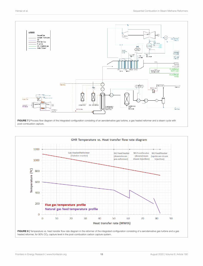
FIGURE 7 | Process flow diagram of the integrated configuration consisting of an aeroderivative gas turbine, a gas heated reformer and a steam cycle with
post-combustion capture.
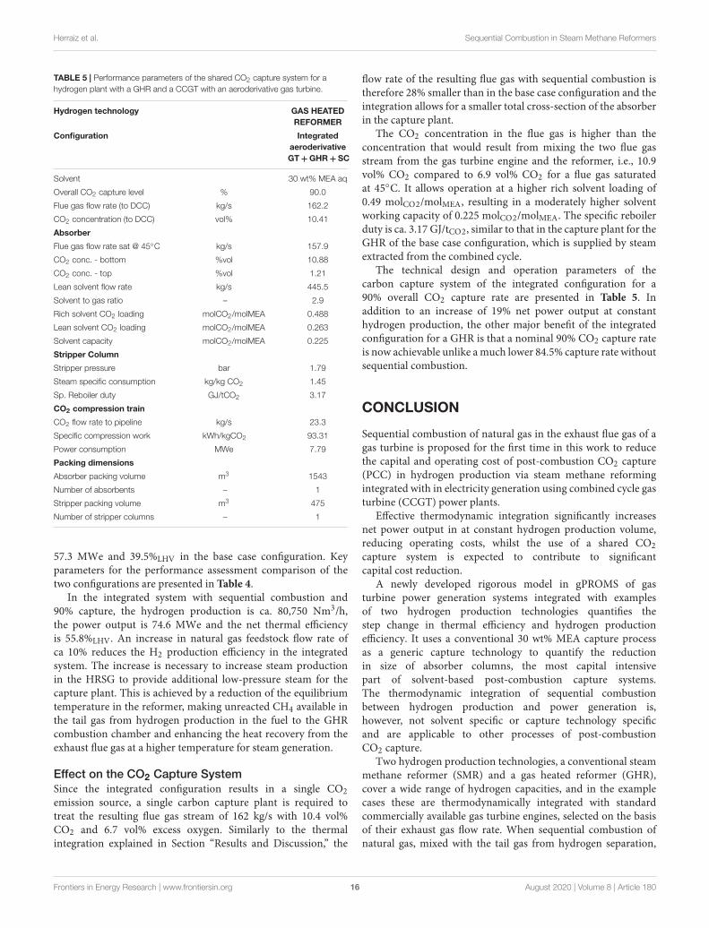
FIGURE 8 | Temperature vs. heat transfer flow rate diagram in the reformer of the integrated configuration consisting of a aeroderivative gas turbine and a gas
heated reformer, for 90% CO2 capture level in the post-combustion carbon capture system.
Frontiers in Energy Research | www.frontiersin.org 13 August 2020 | Volume 8 | Article 180
Herraiz et al. Sequential Combustion in Steam Methane Reformers
FIGURE 9 | Temperature vs. heat transfer flow rate diagram in the heat recovery steam generation section of the integrated configuration consisting of a
aeroderivative gas turbine and a gas heated reformer, for 90% CO2 capture level in the post-combustion carbon capture system.
heat recovery from the flue gases, yet additional steam extractionfrom the combined cycle is needed. Steam extraction from thecombined cycle therefore supplies the thermal energy for the twocarbon capture plants.
Limited steam availability in the combined cycle results in anoverall CO2 capture rate of 84.5%. In this instance, the absorbercolumns are respectively sized for 90% capture rate from theCCGT flue gas and 82% capture rate from the GHR flue gas,although other permutations would be possible. The overallCO2 capture rate is also directly determined by the size of theaeroderivative gas turbine and the hydrogen production volume,57 MWe and 80,750 Nm3/h in this case. The reader is referred toSupplementary Appendices B.1, B.2 respectively for all relevantdetails on the technical design and operating parameters of thehydrogen plant and the CCGT power plant equipped with theirrespective carbon capture systems in the base case configuration.
Results and DiscussionOverall Performance of the Integrated System
Since the aeroderivative gas turbine is located upstream of theGHR, the operation of the gas turbine is unaffected and operateswith a power output of 57 MWe and 42.6%LHV thermal efficiencyat ISO ambient conditions and 100% load, with, as previouslystated, the assumption that the additional pressure drop inthe reformer is compensated by the forced draft fan of thecarbon capture plant.
The design and operation of the GHR deviates, however,from the design conditions for air-firing. The relatively lowoxygen concentration in the GT exhaust flue gas, i.e., 13.7 vol%compared to 21 vol% in ambient air, results in a large volumeof flue gas to supply the amount of oxygen needed for completecombustion of the PSA tail gas and natural gas, and to ensureflame stability. Unlike SMRs were the excess oxygen level is as low
as 1 vol%, gas heated reformers operate with much higher excessair resulting in a 8 vol% excess oxygen at the exhaust, as indicatedin Supplementary Appendix B.1. With sequential combustion,the excess oxygen at the exit of the GHR combustor chamberis ca. 6.7 vol%.
Due to the large volume of flue gas, the combustionchamber exit temperature and, thus, the temperature of thecombustion gas entering the convective reformer is lowerthan 1200◦C, i.e., the combustor exit temperature in astand-alone GHR with air-firing. This results in a lowerequilibrium temperature in the reformer for a given heattransfer area and a given pinch temperature, defined here asthe difference between the combustion gas temperature andthe equilibrium temperature. Although the lower equilibriumtemperature shifts the equilibrium toward a lower hydrogenyield, the content of unreacted methane in the PSA tailgas increases, raising the fuel heating value and thus thetemperature of combustion.
Ultimately, the operating conditions and the reactorequilibrium temperature are optimized so that enough steamis produced in the HRSG to achieve a CO2 capture rate of90% for a hydrogen production of ca. 80,750 Nm3/h. Usingas the comburent the gas turbine flue gas with an exhaust fluerate of 148 kg/s and an excess oxygen of 13.5 vol%, the GHRoperates at a combustion gas temperature of 1115◦C and anequilibrium temperature of 815◦C. The relatively small pinchtemperature of 300◦C would require increasing the heat transferarea compared to an air-fired GHR with a pinch temperature of350◦C. Due to the smaller methane conversion in the catalytictubes, the natural gas flow rate used as feedstock increases from5.9 kg/s to 6.6 kg/s.
Sequential combustion of additional fuel in a GT exhaust fluegas also leads to a higher temperature of the flue gas entering
Frontiers in Energy Research | www.frontiersin.org 14 August 2020 | Volume 8 | Article 180
Herraiz et al. Sequential Combustion in Steam Methane Reformers
TABLE 4 | Performance parameters of the hydrogen plant with a gas heated reformer and the CCGT power plant for both the base case configuration and the
integrated configuration.
Hydrogen technology GAS HEATED REFORMER
Configuration H2 plant Power plant Integrated Integrated
GHR + PCC CCGT with
aero-GT + PCC
aero
GT + GHR +
SC + PCC
84.5% CO2
capture rate
aero
GT + GHR +
SC + PCC
90% CO2
capture rate
Hydrogen production
Hydrogen production Nm3/h 80749 – 80749 80749
Hydrogen production kg/s 1.86 – 1.86 1.86
Total Energy in product MWth 224 – 224 224
NG Feedstock flow rate kg/s 5.90 – 6.59 6.59
H2 production efficiency [1] % 78.91 – 70.56 70.56
Power generation
Gas Turbine power output MWe – 57.00 57.00 57.00
Steam turbine power output MWe – 8.65 27.91 26.62
Feed water pumps power consumption MWe – 0.11 0.24 0.24
Booster fan power consumption MWe 0.49 0.83 0.90 0.90
Solvent pumps power consumption MWe 0.07 0.03 0.11 0.11
CO2 compression train power consumption MWe – 6.78 7.31 7.79
Net power output MWe 0 57.34 76.36 74.59
Additional power output MWe – – 19.01 –
Thermal input - NG fuel MWth 23.59 133.76 146.92 146.92
Net thermal efficiency [2] %LHV 0 42.87 57.09 55.76
Flue gas flow rate kg/s 77.74 147.73 162.21 162.21
Flue gas CO2 concentration %vol CO2 14.06 3.37 10.41 10.41
Steam from combined cycle kg/s 0 20.15 35.54 35.54
Steam to PCC reboiler kg/s 9.64 20.15 31.21 33.24
CO2 capture level % 81.86 90.00 84.50 90.00
Overall CO2 capture level % 84.5 84.5 90.0
Reboiler duty GJ/tCO2 3.17 3.36 3.17 3.17
CO2 flow rate to pipeline kg/s 13.35 6.92 22 23.3
Note [1] Hydrogen production (MWth)/thermal input as NG fuel and NG feedstock (MWth). Note [2] Electrical power output (MWe)/thermal input as NG fuel to both the
GT burner and the GHR burner (MWth).
the heat recovery section. The flue gas enters the HRSG at ca.724◦C, increasing the rate of steam flow and hence the steamturbine power output. The maximum steam temperature is,however, limited to a typical 600◦C at the inlet of the highpressure steam turbine cylinder. The temperature profile alongthe flue gas pathway is illustrated in Figures 8, 9. Figure 8 showsthe temperature pinch diagram of the reformer and Figure 9
shows the temperature pinch diagram of the heat recovery steamgenerator. For a hydrogen production of ca. 80,750 Nm3/h and90% overall CO2 capture rate, the integrated configuration of aGHR and a CCGT with an aeroderivative gas turbine operatesat 73 MWe power output and presents a thermal efficiency of54.7%LHV. Key performance parameters are included in Table 4.
In order to conduct the comparative performance assessmenton a consistent basis, two cases of the integrated configurationare reported in Table 4. The first case operates at an overall CO2
capture rate of 84.5%, i.e., identical to the highest possible capturerate achievable in the base case configuration using the remainingsteam from the CCGT power plant. This level of capture isunlikely to be acceptable and is used solely for the purpose of arigorous comparison on the basis of capture levels. The secondcase achieves a nominal 90% CO2 capture rate.
For the overall CO2 capture rate of 84.5%, the integratedconfiguration presents a higher net power output of 76.4 MWedue to the increase in the steam turbine power output, anda higher net thermal efficiency of 57.1%LHV, compared to
Frontiers in Energy Research | www.frontiersin.org 15 August 2020 | Volume 8 | Article 180
Herraiz et al. Sequential Combustion in Steam Methane Reformers
TABLE 5 | Performance parameters of the shared CO2 capture system for a
hydrogen plant with a GHR and a CCGT with an aeroderivative gas turbine.
Hydrogen technology GAS HEATED
REFORMER
Configuration Integrated
aeroderivative
GT + GHR + SC
Solvent 30 wt% MEA aq
Overall CO2 capture level % 90.0
Flue gas flow rate (to DCC) kg/s 162.2
CO2 concentration (to DCC) vol% 10.41
Absorber
Flue gas flow rate sat @ 45◦C kg/s 157.9
CO2 conc. - bottom %vol 10.88
CO2 conc. - top %vol 1.21
Lean solvent flow rate kg/s 445.5
Solvent to gas ratio – 2.9
Rich solvent CO2 loading molCO2/molMEA 0.488
Lean solvent CO2 loading molCO2/molMEA 0.263
Solvent capacity molCO2/molMEA 0.225
Stripper Column
Stripper pressure bar 1.79
Steam specific consumption kg/kg CO2 1.45
Sp. Reboiler duty GJ/tCO2 3.17
CO2 compression train
CO2 flow rate to pipeline kg/s 23.3
Specific compression work kWh/kgCO2 93.31
Power consumption MWe 7.79
Packing dimensions
Absorber packing volume m3 1543
Number of absorbents – 1
Stripper packing volume m3 475
Number of stripper columns – 1
57.3 MWe and 39.5%LHV in the base case configuration. Keyparameters for the performance assessment comparison of thetwo configurations are presented in Table 4.
In the integrated system with sequential combustion and90% capture, the hydrogen production is ca. 80,750 Nm3/h,the power output is 74.6 MWe and the net thermal efficiencyis 55.8%LHV. An increase in natural gas feedstock flow rate ofca 10% reduces the H2 production efficiency in the integratedsystem. The increase is necessary to increase steam productionin the HRSG to provide additional low-pressure steam for thecapture plant. This is achieved by a reduction of the equilibriumtemperature in the reformer, making unreacted CH4 available inthe tail gas from hydrogen production in the fuel to the GHRcombustion chamber and enhancing the heat recovery from theexhaust flue gas at a higher temperature for steam generation.
Effect on the CO2 Capture System
Since the integrated configuration results in a single CO2
emission source, a single carbon capture plant is required totreat the resulting flue gas stream of 162 kg/s with 10.4 vol%CO2 and 6.7 vol% excess oxygen. Similarly to the thermalintegration explained in Section “Results and Discussion,” the
flow rate of the resulting flue gas with sequential combustion istherefore 28% smaller than in the base case configuration and theintegration allows for a smaller total cross-section of the absorberin the capture plant.
The CO2 concentration in the flue gas is higher than theconcentration that would result from mixing the two flue gasstream from the gas turbine engine and the reformer, i.e., 10.9vol% CO2 compared to 6.9 vol% CO2 for a flue gas saturatedat 45◦C. It allows operation at a higher rich solvent loading of0.49 molCO2/molMEA, resulting in a moderately higher solventworking capacity of 0.225 molCO2/molMEA. The specific reboilerduty is ca. 3.17 GJ/tCO2, similar to that in the capture plant for theGHR of the base case configuration, which is supplied by steamextracted from the combined cycle.
The technical design and operation parameters of thecarbon capture system of the integrated configuration for a90% overall CO2 capture rate are presented in Table 5. Inaddition to an increase of 19% net power output at constanthydrogen production, the other major benefit of the integratedconfiguration for a GHR is that a nominal 90% CO2 capture rateis now achievable unlike amuch lower 84.5% capture rate withoutsequential combustion.
CONCLUSION
Sequential combustion of natural gas in the exhaust flue gas of agas turbine is proposed for the first time in this work to reducethe capital and operating cost of post-combustion CO2 capture(PCC) in hydrogen production via steam methane reformingintegrated with in electricity generation using combined cycle gasturbine (CCGT) power plants.
Effective thermodynamic integration significantly increasesnet power output in at constant hydrogen production volume,reducing operating costs, whilst the use of a shared CO2
capture system is expected to contribute to significantcapital cost reduction.
A newly developed rigorous model in gPROMS of gasturbine power generation systems integrated with examplesof two hydrogen production technologies quantifies thestep change in thermal efficiency and hydrogen productionefficiency. It uses a conventional 30 wt% MEA capture processas a generic capture technology to quantify the reductionin size of absorber columns, the most capital intensivepart of solvent-based post-combustion capture systems.The thermodynamic integration of sequential combustionbetween hydrogen production and power generation is,however, not solvent specific or capture technology specificand are applicable to other processes of post-combustionCO2 capture.
Two hydrogen production technologies, a conventional steammethane reformer (SMR) and a gas heated reformer (GHR),cover a wide range of hydrogen capacities, and in the examplecases these are thermodynamically integrated with standardcommercially available gas turbine engines, selected on the basisof their exhaust gas flow rate. When sequential combustion ofnatural gas, mixed with the tail gas from hydrogen separation,
Frontiers in Energy Research | www.frontiersin.org 16 August 2020 | Volume 8 | Article 180
Herraiz et al. Sequential Combustion in Steam Methane Reformers
in the gas turbine exhaust gas takes place in the burner ofthe reformers, a single CO2 emission source with significantlylower flow rates by 34%, in the SMR, and by 28%, in theGHR, reduces the number of absorber columns compared toequivalent non-integrated systems. In addition, the flow rateand the temperature of the flue gas entering the heat recoverysteam generator (HRSG) increase, leading to additional steamproduction for electricity generation.
The conventional SMR is located downstream of an H-classgas turbine engine followed by a three-pressure level HRSG,supplying steam for power generation in the combined cycle, anda capture plant with two absorber columns. The integrated systemproduces ca. 696,400 Nm3/h of H2 with a net power output of 652MWe at a net thermal efficiency of 38.9%LHV. This correspondsto 34 MWe of additional power output, increasing efficiencyby 4.9% points, and makes one absorber column redundant,compared to the equivalent non-integrated system producing thesame volumes of H2. A CO2 concentration of 15 vol% allowseffective operation of the 30 wt% MEA capture process at highsolvent capacity, resulting in a reduction of absorber structuredpacking volume of 18% and a lower thermal energy for solventregeneration by 4.3%.
The dedicated GHR is located downstream of anaeroderivative gas turbine engine followed by a two-pressurelevel HRSG, supplying steam for power generation in thecombined cycle, and capture plant with one absorber column.The integrated system produces ca. 80,750 Nm3/h of H2 witha net power output of 73 MWe and a net thermal efficiency of54.7%LHV. This corresponds to 13 MWe of additional poweroutput, increasing efficiency by 13.5% points, and reducesthe number of absorber columns necessary from two to one,compared to the equivalent non-integrated system producing thesame volumes of H2.
The article also presents new insights for the design andoperation of reformers integrated with gas turbines. First,sequential combustion enables additional steam production inthe gas turbine/GHR system to achieve CO2 capture rates of90%, or higher if necessary, compared to 84.5% in the equivalentnon-integrated system. This is achieved by lowering the reactortemperature to increase the non-reacted methane concentrationin the recirculated tail gas. Second, the operation of the gasturbine engine is unaffected since sequential combustion takesplace in the reformer furnace or combustion chamber. Thiswould make operating the gas turbine, HRSG and capture whenthe reformer is turned off possible.
The reformer is, however, designed for a change in thecomburent composition and, in the case of a SMR, an increaseof convective heat transfer rate over the radiative heat transferrate. The lower oxygen concentration in the gas turbine exhaustflue gas, i.e., 11.3 vol% in a H-class gas turbine and 13.7 vol% inan aeroderivative gas turbine, compared to 21 vol% in ambient
air, results in larger flow rates to supply the necessary amountof oxygen. This leads to a lower firing temperature and, thus, asmaller pinch temperature in the reformer, reducing the drivingforce for heat transfer. A large heat transfer surface area is likelyto be required in the catalytic tubes of the reformer to maintainthe equilibrium temperature at the design values and achieve ahigh hydrogen yield. Further work would be required to examinethe operation of the reformer and the capture plant when the gasturbine is turned off.
These are important design considerations, to allow forflexible operating strategies for the generation of low-carbonhydrogen independently of low-carbon electricity, and vice-versa, when it makes economic sense to do so. Designing forflexible operation could be used to achieve further cost reductionvia an increase of the utilization factor of the CO2 capture plant,since in future energy systems, seasonal variation in demandfor hydrogen may indeed follow, to some extent, the seasonalpatterns currently observed for natural gas, whilst electricity isexpected to continue to be traded as a volatile commodity on adaily or hourly basis.
DATA AVAILABILITY STATEMENT
All datasets generated for this study are included in thearticle/Supplementary Material.
AUTHOR CONTRIBUTIONS
JG, ML, and LH conceived the present idea. LH developed themodel and performed the simulations and wrote the manuscriptwith support from ML and HC. ML and JG contributed tothe discussion of the results and the findings. ML, JG, and HCcontributed to the final manuscript. All authors provided criticalfeedback and helped shape the research, analysis and manuscript.
FUNDING
The work presented in this manuscript is part of theresearch core program on capture of the UK Carbon Captureand Storage Research Centre (UKCCSRC), funded by theEPSRC (EP/P026214/1).
SUPPLEMENTARY MATERIAL
The Supplementary Material for this article can be foundonline at: https://www.frontiersin.org/articles/10.3389/fenrg.2020.00180/full#supplementary-material
REFERENCES
Air Products (2011). Texas Carbon Capture and Sequestration Project [WWW
Document]. Available at: http://www.airproducts.com/company/news-center/