16
1 Training and Installation Manual for Polypropylene Random Copolymer (PPr) pipes and fittings Written by: Dewald Burzynski May 2014
| Date post: | 27-Dec-2015 |
| Category: |
Documents |
| Upload: | dewald-tjatjarag-burzynski |
| View: | 88 times |
| Download: | 10 times |

1
Training and
Installation Manual for
Polypropylene Random
Copolymer (PPr) pipes
and fittings Written by: Dewald Burzynski
May 2014

2
Table of Contents
1. What is PPr
2. History of PPr
3. Uses of PPr
4. Care of PPr
5. Care of Welder
6. Welding process
- Setting up the welder
- Step by Step
7. Repair Process
8. Installation Requirements
- Expansion
- Bracket distances
- Insulation
- Chasing
9. Pressure Testing
I, ...................................................................................................... hereby acknowledge training on the
above marked subjects and I confirm that I have understood each module. I realize that this training in no
way proves or infers competence in the installation of Serbco WP PPr pipes and fittings. A further
assessment of skills will take place to acknowledge competence.
............................................................. ............................................................. Trainee Trainer
...........................................................
Date

3
What is PPr?
PPr is short for Polypropylene Random Co-polymer. It is a combination of Propylene gas and a small amount of Ethylene gas. These gasses, which are a by-product of petroleum manufacture, are combined to create the raw materials used to produce PPr pipes and fittings. PPr was developed to obtain the best long term heat stability, slow crack growth resistance performance and welding performance as compared to regular Polypropylene.
History of PPr
German chemist, Karl Rehn, and Giulio Natta first polymerized propylene to a crystalline isotactic polymer
in March 1954. This discovery soon led to a commercial production of polypropylene starting in 1957.
Others claimed the discovery, as often occurs when a general body of knowledge is used, and this
litigation was not resolved until 1989. This very popular plastic is one that many different manufacturers
use for a number of different products.
Uses of PPr
PPr has been used in many different forms but mainly is used in piping due to its excellent properties.
-Low cost makes it budget friendly for a wide number of uses
-Has a moderate strength and stability
-Has flexibility, which makes it easy to mould into different shapes
-Colourfast, this means that any colours will stay bright and beautiful
-Resistant to fatigue, which allows it to be used for things such as water bottle hinges and spouts
-Offers good insulation for pipes, cables, and more
-Chemically resistant to most oils and solvents
-Excellent impact strength
-Low coefficient of friction
-Excellence moisture resistance
-High temperature resistance which means it can be used in laboratories
PPr is therefore ideal to be used a s a material for piping fluids from -20°C up to +90°C. Various fluids have been reticulated using PPr. Some of these include Sulphuric Acid, Chilled Water (HVAC), Glycol solutions, Domestic Hot and Cold Water, Compressed Air etc. Full lists of the fluids that are suitable for transportation via PPr pipes are available in our Technical Manual.

4
Care of PPr
- DO NOT let PPr pipes be exposed to direct sunlight. Store the pipes in a covered or enclosed space.
- DO NOT install PPr pipes in direct sunlight UNLESS it has been shielded by way of a sleeve or at the very minimum, two coats of paint.
- DO NOT use open flame on PPr pipes. - DO NOT stack PPr pipes higher than 1.5m.
- ALWAYS Store the pipes and fittings correctly. - ALWAYS ensure your threads are sealed with PTFE/Teflon tape and not with Hemp. - ALWAYS transport the pipes and fittings carefully
Care of Welder
- DO NOT weld with a faulty welder. - DO NOT place the welder on its side on the floor. - DO NOT transport the welder in any other container except the metal box provided. - DO NOT use pliers or any other equipment except those provided, to fasten the dollies.
- ALWAYS place the welder in its stand.
- ALWAYS ensure welder is set at correct temperature.
- ALWAYS clean the dollies with acetone after use.
- ALWAYS store the welder in the correct metal box.
- ALWAYS endure that the dolly’s surface is covered by the heating plate of the welder.

5
Welding Process
The welding process is a step by step process that needs to be followed to achieve the longest lasting and
strongest weld possible.
Setup of the Welder
- Make sure the welder is plugged in to a reliable source of electricity and do not use a lead line
that is too thin for its relative length
- Check that the welding temperature is set to 260°C
- Dollies must be securely fastened to the heating plate but not over tightened.
Step by Step Welding Process
Step 1.
Ensure the welder is stable and that it is at the required welding temperature (260°C ±5°C)
Step 2.
Cut the pipe to length with the correct cutter ensuring that there are no burs. Prepare the pipe and fitting
making sure the surfaces are free from dirt and oil.

6
Step 3.
Mark the welding depth on the pipe with the Welding Depth Gauge or by measuring the depth with a
measuring tape.
Step 4.
Push the pipe and fitting onto the dollies applying even strength to both sides. Ensure that you maintain
the Heating Time and Welding Depth as per Table below. The Heating time is strictly from the time which
the pipe and fitting touch the dollies. Avoid twisting the pipe and fitting.
Step 5.
Remove the pie and fitting from the dollies and immediately push them into each other. Maintain the
correct orientation. Slight adjustment can be done during this step.

7
Step 6.
Allow the join to cool and it is ready for use.
Welding Parameters
Outer Diameter
(mm)
Melting Depth (mm)
Heating Time (sec)
Processing Time (sec)
Cooling time (min)
20 14 5 4 3
25 15.5 7 4 3
32 17.5 8 4 4
40 20 12 6 4
50 23 18 6 5
63 26 24 6 6
75 28.5 30 8 8
90 33 40 8 8
110 39 50 10 10
125 41 58 11 10
160 46 80 15 15

8
Repair Process
The repair process is very simple and is achieved by welding a Repair Stick into the hole. A repair kit will
be necessary to repair the issue.
Step 1.
The damaged hole needs to be drilled clean. Any hole smaller than 6mm needs to be drilled with a 6mm
steel bit. Any hole between 6.5mm and 9.5mm needs to be drilled with a 10mm steel bit.
Step 2.
Clean the hole with a cloth ensuring the weld area is clean and dry. Water from the pipe must not come
into direct contact with the weld area.
9
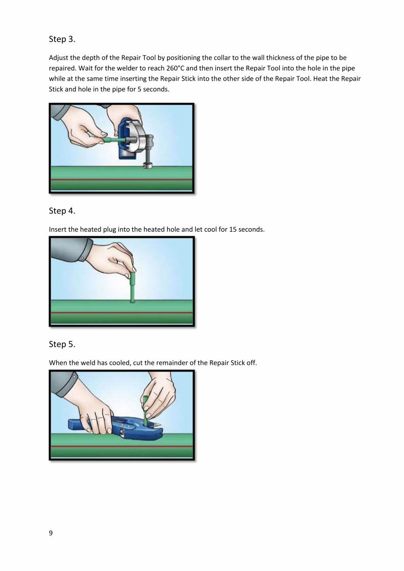
Step 3.
Adjust the depth of the Repair Tool by positioning the collar to the wall thickness of the pipe to be
repaired. Wait for the welder to reach 260°C and then insert the Repair Tool into the hole in the pipe
while at the same time inserting the Repair Stick into the other side of the Repair Tool. Heat the Repair
Stick and hole in the pipe for 5 seconds.
Step 4.
Insert the heated plug into the heated hole and let cool for 15 seconds.
Step 5.
When the weld has cooled, cut the remainder of the Repair Stick off.

10
Installation Requirements
Expansion
PPr pipe has a Coefficient of Linear Expansion of 0.15mm/m°C. More simply put, for every degree of
temperature change a meter length of pipe will expand or contract by 0.15mm. A pipe will expand and
contract due to the temperature difference of the fluid that is being transported (e.g. Hot Water), as well
as the temperature that it is exposed to from the immediate environment (e.g.. Roof space). This
expansion and contraction will need to be compensated for. The result of not correctly addressing the
issue can be seen in Picture 1 and Picture 2 below. The pipe seeks the path of least resistance and will
end up “snaking”.
The way to avoid this problem is by using Expansion Loops (Figure 1) and Expansion Arms (Figure 2) to
take up the expansion.
Picture 1
Picture 2
Figure 1

11
As can be seen in the above illustrations, the use of Fixed Point and Sliding Point bracketing is necessary
to accommodate the movement of the pipe.
A Fixed Point (FP) is a bracket that clamps the pipe that it does not move at that point. A Sliding Point (SP)
is a bracket that holds the pipe in place but allows the pipe to move with expansion. Please ensure that
you get the correct dimensions for the expansion loops and that Fixed Point and Sliding Point bracketing
is correctly fastened.
The below table shows a typical example of the various dimensions of the expansion loops:
Distance of run: 20 meters (L)
Temperature difference from installed: 40°C
Size Pipe (mm) Length (mm) ( Ls) Width (mm)
20 520 390
25 581 390
32 653 390
40 735 390
50 822 390
63 922 390
75 1006 390
90 1102 390
110 1219 390
Figure 2

12
Bracket Distances
Bracketing is a most important installation feature and needs to be completed to manufacturer
specification. If bracketing is not installed correctly, sagging of the pipes can take place and through that
airlocks may occur. In addition, it does not look professional when pipes are sagging.
The bracket distances change due to three variables:
- Size of the pipe
- Pressure rating
- Temperature carried
Below are tables that break down the differences of pipe and temperature carried in them.
Size (mm) PN10
Temp 20°C
Distance (cm) 20 75
25 85 32 100
40 110
50 120 63 140
75 150 90 165
110 180
Size (mm) PN16
Temp 40°C 50°C 60°C 70°C
Distance (cm) 20 70 65 60 50
25 75 70 65 60
32 80 80 75 75 40 105 100 95 90
50 110 110 110 100 63 130 130 115 105
75 160 150 145 120
90 160 150 140 125
110 170 170 165 140

13
There are various ways to fix PPr pipes. For soffit mounting we recommend the use of “Hilti/Sikla” type
clamps (Picture 4) with Threaded Rod and Drop-in Anchors. For surface mounting U-type clips (Picture 5)
are recommended. For the fastening of PPr pipes in Roof Space that has truss distances that exceed the
bracketing distance, the diagram in (Picture 3) can be used. Cable trays can also be used however this is
an expensive option unless multiple lines are being laid in the tray.
Picture 3 Picture 4
Picture 5

14
Insulation
All Domestic Hot Water pipes have to be insulated against heat losses. According to the SANS 10400XA
regulation, the R-value (Resistance to Heat Transfer) has to be a minimum of 1. There are mathematical
methods of determining the R-value of a material. Below is a Table with the relative R-values and
Insulation thicknesses for PPr pipes.
Diameter (mm) Insulation Thickness
(mm) R-value Combined
20 9 3.22
25 9 2.76
32 9 2.30
40 13 2.56
50 13 2.17
63 19 2.42
75 19 2.13
90 19 1.86
110 25 1.97
125 25 1.79
140 25 1.64
160 25 1.49
Chasing
PPr pipes can be chased into the walls without deterioration of wall strength (Chase does not need to be
deeper). The cracking of plaster due to the expansion of the pipe does not occur with PPr pipes (PPr
expands away from the force of the plaster i.e. inwardly). Adding protection against the cement plaster is
not necessary because PPr is un-reactive with the lime in the cement mixture.
Picture 6
Picture 7

15
Pressure Testing
A hydraulic pressure test must be performed after each installation. The test pressure has to be 1.5 times
the operating pressure. During the pressure test, the expansion of the pipe has to be considered. The
difference between the temperature of the pipe and the ambient temperature may lead to pressure
change. 10°C temperature change relates to a 0.5 to 1 bar pressure difference. It is recommended to
perform the pressure test of polymer piping systems at the maximum ambient temperature.
The Pressure test consists of two parts:
- Preliminary Test
- Principal Test
Preliminary pressure has to be 1.5% the operating pressure. The pressure test has to be taken twice with
duration of 30 minutes and an interval of 10 minutes between them. During the second 30 minutes test,
the pressure drop should not exceed 0.6bar and no leakage should occur
Principal test has to be undertaken immediately after the Preliminary test. The test period is two hours.
The test pressure determined after Preliminary test should not fall by more than 0.2bar.
Below is an Installation Test Record that can be used when reporting on the Pressure Test Procedure. Be
sure to complete the form in full before handing it to your client.

16


