• SAFETY PRECAUTIONS • (Be sure to read these instructions before using the product.)
Before using this product, please read this manual and the relevant manuals introduced in this manual carefully and pay full attention to safety to handle the product correctly. Note that these precautions apply only to this product. Refer to the user's manual of the CPU module for the programmable controller system safety precautions. In this manual, the safety instructions are ranked as "DANGER" and "CAUTION".
Indicates that incorrect handling may cause hazardous conditions, resulting in death or severe injury. Indicates that incorrect handling may cause hazardous conditions, resulting in medium or slight personal injury or physical damage.
Note that the CAUTION level may lead to a serious consequence according to the circumstances. Always follow the instructions of both levels because they are important to personal safety. Please save this manual to make it accessible when required and always forward it to the end user.
A-2
[Design Instructions]
CAUTION Do not bunch the control wires or communication cables with the main circuit or power wires, or install them close to each other. They should be installed 100mm(3.9inch) or more from each other. Not doing so could result in noise that may cause malfunction.
[Installation Instructions]
CAUTION Use the programmable controller in an environment that meets the general specifications contained in the user's manual of the CPU module to use. Using this programmable controller in an environment outside the range of the general specifications could result in electric shock, fire, erroneous operation, and damage to or deterioration of the product.
While pressing the installation lever located at the bottom of module, insert the module fixing tab into the fixing hole in the base unit until it stops. Then, securely mount the module with the fixing hole as a supporting point. Incorrect loading of the module can cause a malfunction, failure or drop. When using the programmable controller in the environment of much vibration, tighten the module with a screw.
Tighten the screw in the specified torque range. Undertightening can cause a drop, short circuit or malfunction. Overtightening can cause a drop, short circuit or malfunction due to damage to the screw or module.
Completely turn off the externally supplied power used in the system before mounting or removing the module. Not doing so could result in damage to the product.
Do not directly touch the conductive area or electronic components of the module. Doing so may cause malfunction or failure in the module.
A-3
[Wiring Instructions]
CAUTION When turning on the power and operating the module after installation and wiring are completed, always attach the terminal cover that comes with the product. There is a risk of electric shock if the terminal cover is not attached.
Perform correct pressure-displacement, crimp-contact or soldering for external wire connections using the tools specified by the manufactures. Incorrect connection may cause short circuits, fire, or malfunction.
Attach connectors to the module securely. Be sure to fix communication cables or power supply cables leading from the module by placing them in the duct or clamping them. Cables not placed in the duct or without clamping may hang or shift, allowing them to be accidentally pulled, which may cause a module malfunction and cable damage.
Before connecting the cables, check the type of interface to be connected. Connecting or erroneous wiring to the wrong interface may cause failure to the module and external devices.
Tighten the terminal screws within the range of specified torque. If the terminal screws are loose, it may result in short circuits or malfunction. If the screws are tightened too much, it may cause damage to the screw and/or the module, resulting in fallout, short circuits or malfunction.
When removing the communication cable or power supply cable from the module, do not pull the cable. When removing the cable with a connector, hold the connector on the side that is connected to the module. When removing the cable connected to the terminal block, first loosen the screws on the part that is connected to the terminal block. Pulling the cable that is still connected to the module may cause malfunction or damage to the module or cable.
Be sure there are no foreign substances such as sawdust or wiring debris inside the module. Such debris could cause fires, damage, or erroneous operation.
The module has an ingress prevention label on its top to prevent foreign matter, such as wire offcuts, from entering the module during wiring. Do not peel this label during wiring. Before starting system operation, be sure to peel this label because of heat dissipation.
A-4
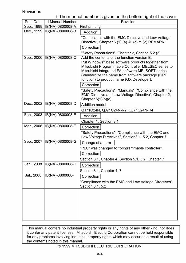
Revisions
The manual number is given on the bottom right of the cover. Print Date Manual Number Revision Sep., 1999 IB(NA)-0800008-A First printing Dec., 1999 IB(NA)-0800008-B Addition
"Compliance with the EMC Directive and Low Voltage Directive", Chapter 6 (1) (a) · (c) ·(2) REMARK Correction "Safety Precautions", Chapter 2, Section 5.2 (3)
Sep., 2000 IB(NA)-0800008-C Add the contents of the function version B. Put Windows® base software products together from Mitsubishi Programmable Controller MELSEC series to Mitsubishi integrated FA software MELSOFT series. Standardize the name from software package (GPP function) to product name (GX Developer). Correction "Safety Precautions", "Manuals", "Compliance with the EMC Directive and Low Voltage Directive", Chapter 2, Chapter 6(1)(b)(c).
Dec., 2002 IB(NA)-0800008-D Addition model QJ71C24N, QJ71C24N-R2, QJ71C24N-R4
"Compliance with the EMC and Low Voltage Directives", Section 3.1, 5.2
This manual confers no industrial property rights or any rights of any other kind, nor does it confer any patent licenses. Mitsubishi Electric Corporation cannot be held responsible for any problems involving industrial property rights which may occur as a result of using the contents noted in this manual.
4. Part Names·································································································· 4 5. External Wiring ···························································································· 6
5.1 Connecting to the RS-232 line································································ 6 5.2 Connecting to the RS-422/485 line························································· 9
The following table lists manuals relating to this product. If necessary, obtain a proper manual in accordance with the intended use. Relevant Manuals
Manual name Manual No. (Model code)
Q Corresponding Serial Communication Module User's Manual (Basic)
SH-080006 (13JL86)
Q Corresponding Serial Communication Module User's Manual (Application)
SH-080007 (13JL87)
Q Corresponding MELSEC Communication Protocol Reference Manual
SH-080008 (13JF89)
Please read the Q Corresponding Serial Communication Module User's Manual (Basic) before using this module.
1
Compliance with the EMC and Low Voltage Directives
(1) For programmable controller system To configure a system meeting the requirements of the EMC and Low Voltage Directives when incorporating the Mitsubishi programmable controller (EMC and Low Voltage Directives compliant) into other machinery or equipment, refer to Chapter 9 "EMC AND LOW VOLTAGE DIRECTIVES" of the QCPU User's Manual (Hardware Design, Maintenance and Inspection). The CE mark, indicating compliance with the EMC and Low Voltage Directives, is printed on the rating plate of the programmable controller.
(2) For the product
No additional measures are necessary for the compliance of this product with the EMC and Low Voltage Directives.
1. Overview
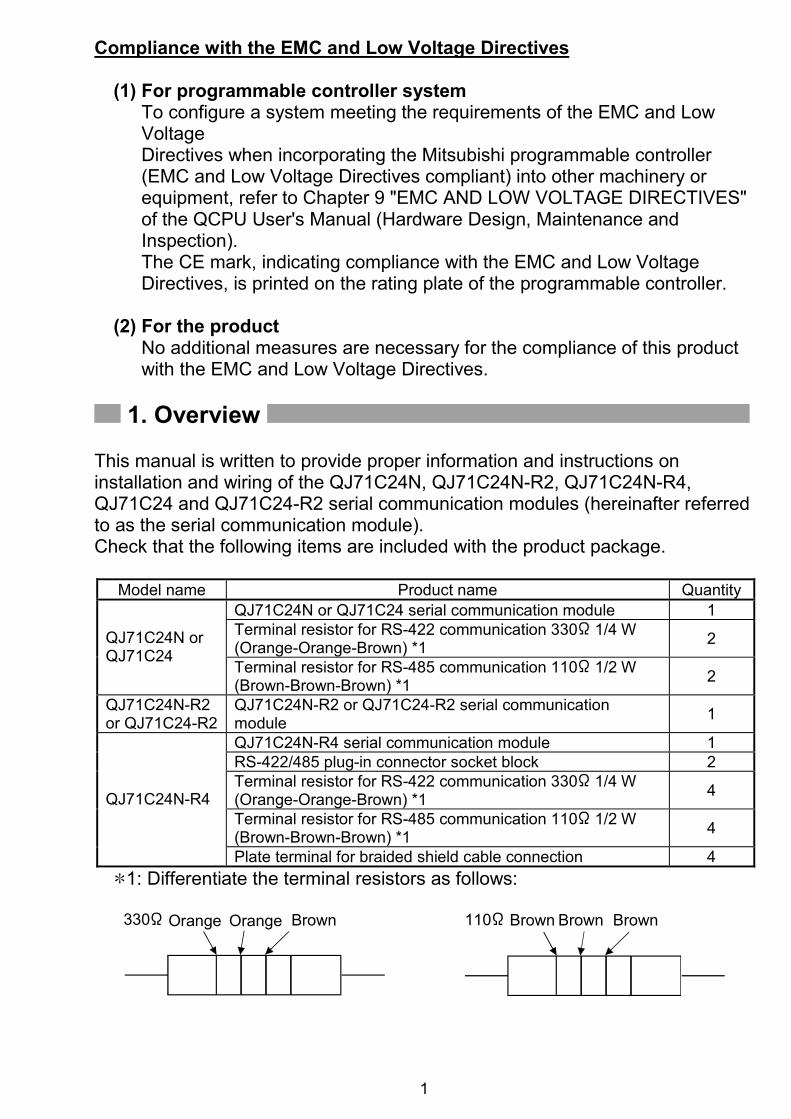
This manual is written to provide proper information and instructions on installation and wiring of the QJ71C24N, QJ71C24N-R2, QJ71C24N-R4, QJ71C24 and QJ71C24-R2 serial communication modules (hereinafter referred to as the serial communication module). Check that the following items are included with the product package.
Model name Product name Quantity QJ71C24N or QJ71C24 serial communication module 1 Terminal resistor for RS-422 communication 330 1/4 W (Orange-Orange-Brown) *1 2 QJ71C24N or
QJ71C24 Terminal resistor for RS-485 communication 110 1/2 W (Brown-Brown-Brown) *1 2
QJ71C24N-R2 or QJ71C24-R2
QJ71C24N-R2 or QJ71C24-R2 serial communication module 1
QJ71C24N-R4 serial communication module 1 RS-422/485 plug-in connector socket block 2 Terminal resistor for RS-422 communication 330 1/4 W (Orange-Orange-Brown) *1 4
Terminal resistor for RS-485 communication 110 1/2 W (Brown-Brown-Brown) *1 4
QJ71C24N-R4
Plate terminal for braided shield cable connection 4 1: Differentiate the terminal resistors as follows:
330 110BrownOrange Orange Brown Brown Brown
2
2. Performance Specifications
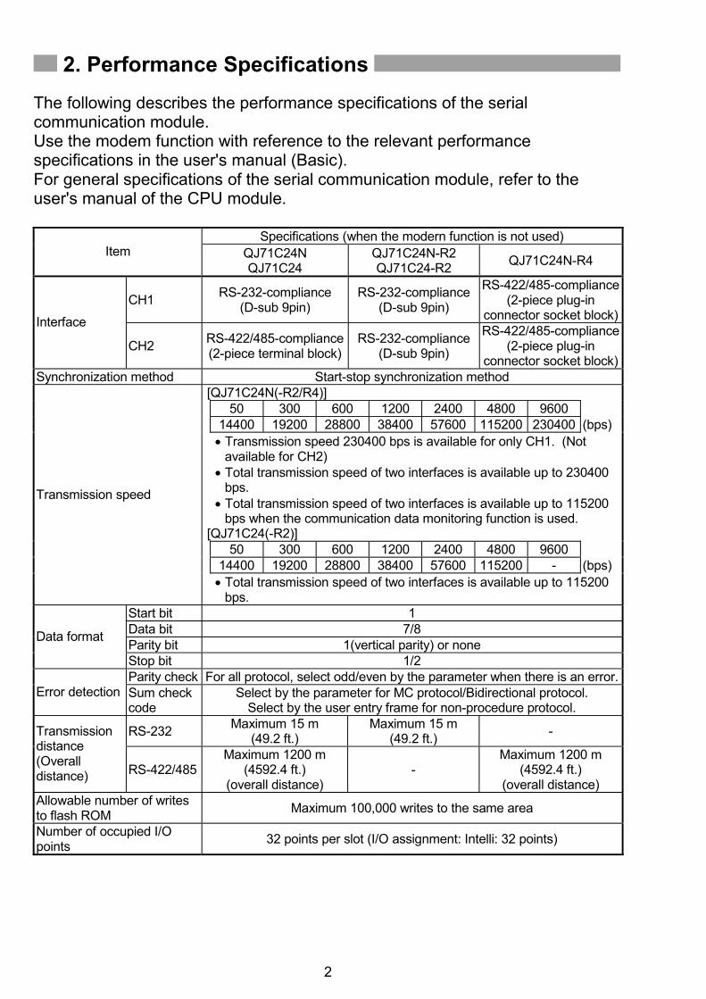
The following describes the performance specifications of the serial communication module. Use the modem function with reference to the relevant performance specifications in the user's manual (Basic). For general specifications of the serial communication module, refer to the user's manual of the CPU module.
Specifications (when the modern function is not used) Item QJ71C24N
[QJ71C24N(-R2/R4)] 50 300 600 1200 2400 4800 9600 14400 19200 28800 38400 57600 115200 230400 (bps) • Transmission speed 230400 bps is available for only CH1. (Not
available for CH2) • Total transmission speed of two interfaces is available up to 230400
bps. • Total transmission speed of two interfaces is available up to 115200
bps when the communication data monitoring function is used. [QJ71C24(-R2)] 50 300 600 1200 2400 4800 9600 14400 19200 28800 38400 57600 115200 - (bps)
Transmission speed
• Total transmission speed of two interfaces is available up to 115200 bps.
Start bit 1 Data bit 7/8 Parity bit 1(vertical parity) or none Data format
Stop bit 1/2 Parity check For all protocol, select odd/even by the parameter when there is an error.
Error detection Sum check code
Select by the parameter for MC protocol/Bidirectional protocol. Select by the user entry frame for non-procedure protocol.
RS-232 Maximum 15 m (49.2 ft.)
Maximum 15 m (49.2 ft.) - Transmission
distance (Overall distance) RS-422/485
Maximum 1200 m (4592.4 ft.)
(overall distance) -
Maximum 1200 m (4592.4 ft.)
(overall distance) Allowable number of writes to flash ROM Maximum 100,000 writes to the same area
Number of occupied I/O points 32 points per slot (I/O assignment: Intelli: 32 points)
3
Specifications (when the modern function is not used)
Item QJ71C24N QJ71C24
QJ71C24N-R2 QJ71C24-R2 QJ71C24N-R4
RS-232 7/0. 127 P HRV-SV Outside diameter 8.5mm (0.33in.) or more (Oki Electric Cable Co., Ltd. Applicable number is specified in .)
are equivalent in the electrical characteristics, but partially different in the outside diameter, internal wire colors, etc.
2: Refer to Section 5.1 for the recommended cable.
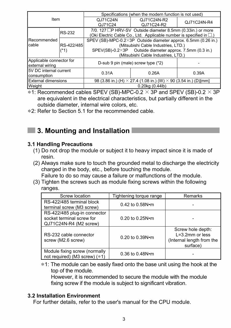
3. Mounting and Installation 3.1 Handling Precautions
(1) Do not drop the module or subject it to heavy impact since it is made of resin.
(2) Always make sure to touch the grounded metal to discharge the electricity charged in the body, etc., before touching the module. Failure to do so may cause a failure or malfunctions of the module.
(3) Tighten the screws such as module fixing screws within the following ranges.
Screw location Tightening torque range Remarks RS-422/485 terminal block terminal screw (M3 screw) 0.42 to 0.58N•m -
RS-422/485 plug-in connector socket terminal screw for QJ71C24N-R4 (M2 screw)
0.20 to 0.25N•m -
RS-232 cable connector screw (M2.6 screw) 0.20 to 0.39N•m
Screw hole depth: L=3.2mm or less
(Internal length from the surface)
Module fixing screw (normally not required) (M3 screw) ( 1) 0.36 to 0.48N•m -
1: The module can be easily fixed onto the base unit using the hook at the
top of the module. However, it is recommended to secure the module with the module fixing screw if the module is subject to significant vibration.
3.2 Installation Environment
For further details, refer to the user's manual for the CPU module.
4
4. Part Names
QJ71C24NQJ71C24 ( 1)
QJ71C24N-R2QJ71C24-R2 ( 2)
QJ71C24N-R4
1)
3)
2)
1)
4)
4)
1)
2)
2)
5) 5)5) *1: The appearance of the QJ71C24 is almost the same as that of the
QJ71C24N, except for the model name part and serial number plate. *2: The appearance of the QJ71C24-R2 is almost the same as that of the
QJ71C24N-R2, except for the model name part and serial number plate.
Name Contents 1) Display LED Display LED (For details, see Section (1).)
2) RS-232 Interface RS232 interface for serial communication with external devices (D-Sub 9pin)
3) RS-422/485 Interface
RS422/485 interface for serial communication with external devices (2-piece terminal block)
4) RS-422/485 Interface
RS422/485 interface for serial communication with external devices (2-piece plug-in socket block)
5) Serial number plate Indicates the serial No. of the serial communication module.
5
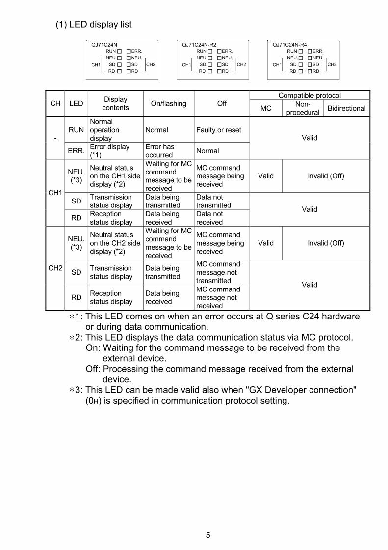
(1) LED display list
ERR.
CH2CH1 SDRD
NEU.SD
NEU.
RD
RUNQJ71C24N
ERR.
CH2CH1 SDRD
NEU.SD
NEU.
RD
RUNQJ71C24N-R2
ERR.
CH2CH1 SDRD
NEU.SD
NEU.
RD
RUNQJ71C24N-R4
Compatible protocol CH LED Display
contents On/flashing Off MC Non-procedural Bidirectional
RUN Normal operation display
Normal Faulty or reset -
ERR. Error display (*1)
Error has occurred Normal
Valid
NEU. (*3)
Neutral status on the CH1 side display (*2)
Waiting for MC command message to be received
MC command message being received
Valid Invalid (Off)
SD Transmission status display
Data being transmitted
Data not transmitted
CH1
RD Reception status display
Data being received
Data not received
Valid
NEU. (*3)
Neutral status on the CH2 side display (*2)
Waiting for MC command message to be received
MC command message being received
Valid Invalid (Off)
SD Transmission status display
Data being transmitted
MC command message not transmitted
CH2
RD Reception status display
Data being received
MC command message not received
Valid
1: This LED comes on when an error occurs at Q series C24 hardware or during data communication.
2: This LED displays the data communication status via MC protocol. On: Waiting for the command message to be received from the
external device. Off: Processing the command message received from the external
device. 3: This LED can be made valid also when "GX Developer connection"
(0H) is specified in communication protocol setting.
6
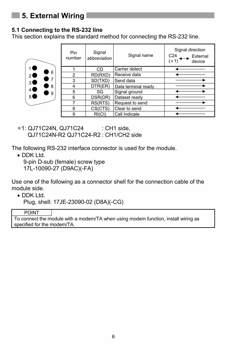
5. External Wiring 5.1 Connecting to the RS-232 line This section explains the standard method for connecting the RS-232 line.
Data terminal readySignal ground
CDRD(RXD)SD(TXD)DTR(ER)
SGDSR(DR)RS(RTS)CS(CTS)
RI(CI)
Pin number
Signal abbreviation
Signal directionExternal device
123456789
C24( 1)
9
12345
678
Signal name
Carrier detectReceive dataSend data
Dataset readyRequest to sendClear to sendCall Indicate
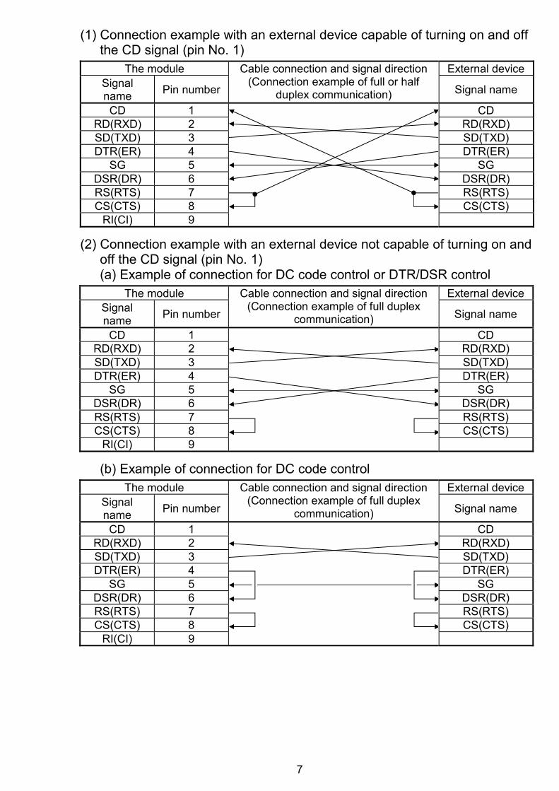
(2) Connection example with an external device not capable of turning on and off the CD signal (pin No. 1) (a) Example of connection for DC code control or DTR/DSR control
The module External device Signal name Pin number
Cable connection and signal direction (Connection example of full duplex
communication) Signal name
CD 1 CD RD(RXD) 2 RD(RXD) SD(TXD) 3 SD(TXD) DTR(ER) 4 DTR(ER)
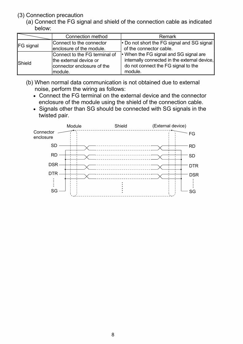
(a) Connect the FG signal and shield of the connection cable as indicated below: Connection method Remark
FG signal Connect to the connector enclosure of the module.
Shield
Connect to the FG terminal of the external device or connector enclosure of the module.
• Do not short the FG signal and SG signal of the connector cable.
• When the FG signal and SG signal are internally connected in the external device, do not connect the FG signal to the module.
(b) When normal data communication is not obtained due to external
noise, perform the wiring as follows: • Connect the FG terminal on the external device and the connector
enclosure of the module using the shield of the connection cable. • Signals other than SG should be connected with SG signals in the
twisted pair.
FG
RD
SD
DTR
DSR
SG
RD
SD
DTR
DSR
SG
Connector enclosure
Module Shield (External device)
9
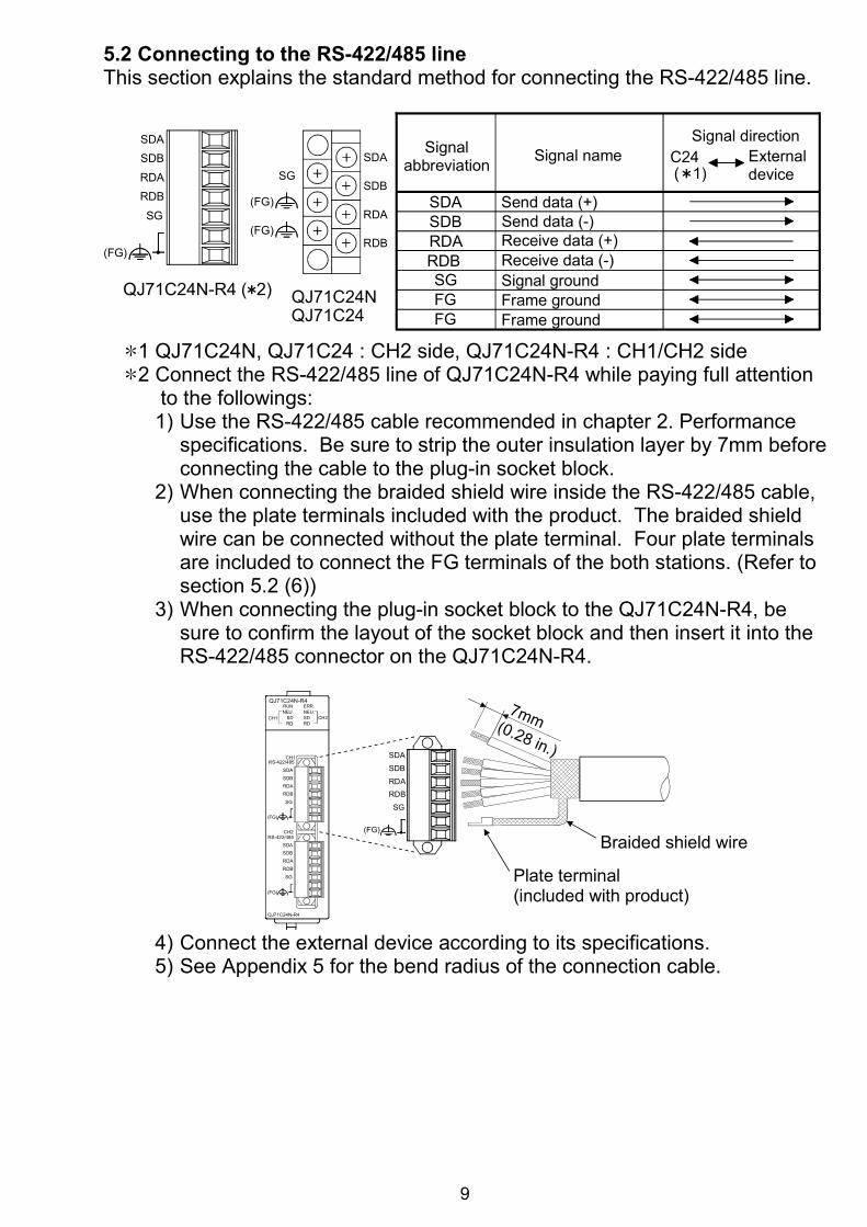
5.2 Connecting to the RS-422/485 line This section explains the standard method for connecting the RS-422/485 line.
Signal abbreviation Signal name
Signal directionExternal device
C24
Signal groundFrame ground
SDBRDARDBSGFG
Frame groundFG
( 1)SGSDA
SDB
RDA
RDB
SG
RDBRDA
SDBSDA
QJ71C24N-R4 ( 2) QJ71C24NQJ71C24
(FG)
(FG)
(FG) SDA Send data (+)Send data (-)Receive data (+)Receive data (-)
1 QJ71C24N, QJ71C24 : CH2 side, QJ71C24N-R4 : CH1/CH2 side 2 Connect the RS-422/485 line of QJ71C24N-R4 while paying full attention
to the followings: 1) Use the RS-422/485 cable recommended in chapter 2. Performance
specifications. Be sure to strip the outer insulation layer by 7mm before connecting the cable to the plug-in socket block.
2) When connecting the braided shield wire inside the RS-422/485 cable, use the plate terminals included with the product. The braided shield wire can be connected without the plate terminal. Four plate terminals are included to connect the FG terminals of the both stations. (Refer to section 5.2 (6))
3) When connecting the plug-in socket block to the QJ71C24N-R4, be sure to confirm the layout of the socket block and then insert it into the RS-422/485 connector on the QJ71C24N-R4.
SG
RDBRDA
SDB
SDA
(FG)
Plate terminal (included with product)
Braided shield wire
7mm (0.28 in.)
CH2
CH1RS-422/485
RS-422/485
QJ71C24N-R4
SG
RDBRDASDB
SG
RDB
RDASDBSDA
SDA
QJ71C24N-R4RUN
RD
NEU.SD
NEU.
RDSDCH1 CH2
ERR.
(FG)
(FG)
4) Connect the external device according to its specifications. 5) See Appendix 5 for the bend radius of the connection cable.
10
POINT
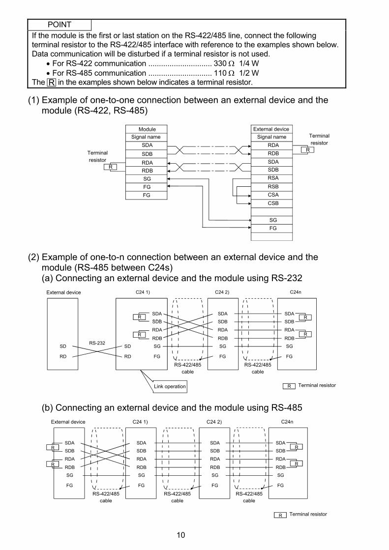
If the module is the first or last station on the RS-422/485 line, connect the following terminal resistor to the RS-422/485 interface with reference to the examples shown below. Data communication will be disturbed if a terminal resistor is not used.
• For RS-422 communication .............................. 330 Ω 1/4 W • For RS-485 communication .............................. 110 Ω 1/2 W
The R in the examples shown below indicates a terminal resistor.
(1) Example of one-to-one connection between an external device and the module (RS-422, RS-485)
Terminal resistor
R
R
ModuleSignal name
SDA
SDBRDARDB
External device
RDARDBSDASDBRSARSBCSACSB
SGFG
SGFGFG
Signal name Terminal resistor
(2) Example of one-to-n connection between an external device and the module (RS-485 between C24s) (a) Connecting an external device and the module using RS-232
Terminal resistor
R
R
R
R
RLink operation
SDA
SDB
RDA
RDB
SG
FG
SDA
SDB
RDA
RDB
SG
FG
SDA
SDB
RDA
RDB
SG
FG
SD
RD
SD
RD
External device C24 1) C24 2) C24n
RS-422/485 cable
RS-422/485 cable
RS-232
(b) Connecting an external device and the module using RS-485
Terminal resistor
R
R
R
SDA
SDB
RDA
RDB
SG
FG
SDA
SDB
RDA
RDB
SG
FG
External device C24 1) C24 2) C24n
RS-422/485 cable
RS-422/485 cable
SDA
SDB
RDA
RDB
SG
FG
R
RSDA
SDB
RDA
RDB
SG
FG
RS-422/485 cable
11
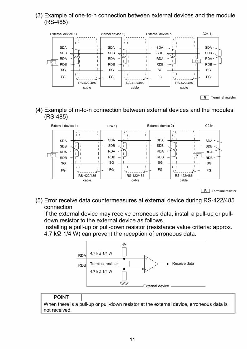
(3) Example of one-to-n connection between external devices and the module
(RS-485)
Terminal registorR
SDASDB
RDA
RDBSG
FG
RS-422/485cable
RS-422/485cable
SDASDB
RDA
RDBSG
FG
R
SDASDB
RDA
RDBSG
FG
SDASDB
RDA
RDBSG
FG
RS-422/485cable
R
External device 1) C24 1)External device 2) External device n
(4) Example of m-to-n connection between external devices and the modules (RS-485)
Terminal resistorR
SDASDB
RDA
RDBSG
FG
External device 1) External device 2)C24 1) C24n
SDASDB
RDA
RDBSG
FG
R
SDASDB
RDA
RDBSG
FG
SDASDB
RDA
RDBSG
FGRS-422/485
cable
R
RS-422/485 cable
RS-422/485 cable
(5) Error receive data countermeasures at external device during RS-422/485 connection If the external device may receive erroneous data, install a pull-up or pull-down resistor to the external device as follows. Installing a pull-up or pull-down resistor (resistance value criteria: approx. 4.7 k 1/4 W) can prevent the reception of erroneous data.
Receive data
4.7 k 1/4 W
4.7 k 1/4 W
Terminal resistor
RDA
RDB+
-
External device
POINT When there is a pull-up or pull-down resistor at the external device, erroneous data is not received.
12
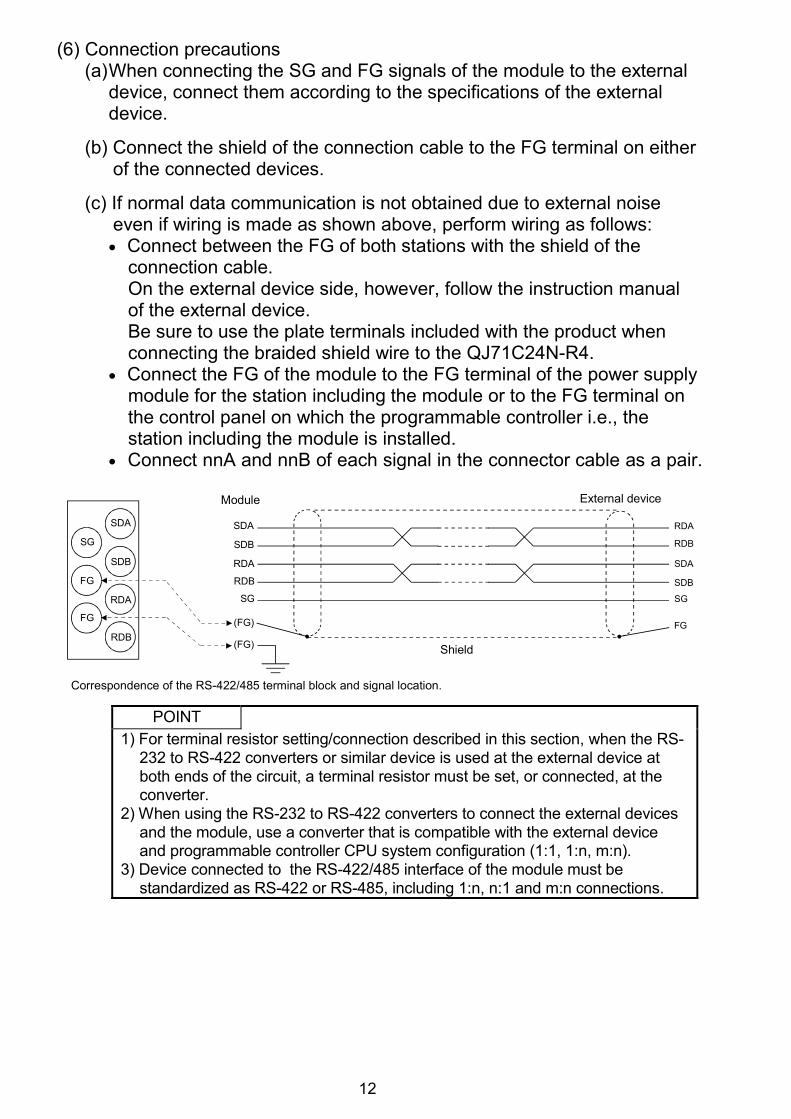
(6) Connection precautions
(a) When connecting the SG and FG signals of the module to the external device, connect them according to the specifications of the external device.
(b) Connect the shield of the connection cable to the FG terminal on either
of the connected devices.
(c) If normal data communication is not obtained due to external noise even if wiring is made as shown above, perform wiring as follows: • Connect between the FG of both stations with the shield of the
connection cable. On the external device side, however, follow the instruction manual of the external device. Be sure to use the plate terminals included with the product when connecting the braided shield wire to the QJ71C24N-R4.
• Connect the FG of the module to the FG terminal of the power supply module for the station including the module or to the FG terminal on the control panel on which the programmable controller i.e., the station including the module is installed.
• Connect nnA and nnB of each signal in the connector cable as a pair.
Correspondence of the RS-422/485 terminal block and signal location.
Shield
Module External device
SDA
SDB
RDA
RDB
SG
(FG)
(FG)
SDA
SDB
RDA
RDB
SG
FG
SG
FG
FG
SDA
SDB
RDB
RDA
POINT 1) For terminal resistor setting/connection described in this section, when the RS-
232 to RS-422 converters or similar device is used at the external device at both ends of the circuit, a terminal resistor must be set, or connected, at the converter.
2) When using the RS-232 to RS-422 converters to connect the external devices and the module, use a converter that is compatible with the external device and programmable controller CPU system configuration (1:1, 1:n, m:n).
3) Device connected to the RS-422/485 interface of the module must be standardized as RS-422 or RS-485, including 1:n, n:1 and m:n connections.
13
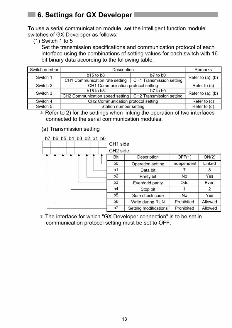
6. Settings for GX Developer To use a serial communication module, set the intelligent function module switches of GX Developer as follows:
(1) Switch 1 to 5 Set the transmission specifications and communication protocol of each interface using the combinations of setting values for each switch with 16 bit binary data according to the following table.
Switch number Description Remarks
b15 to b8 b7 to b0 Switch 1 CH1 Communication rate setting CH1 Transmission setting
Refer to (a), (b)
Switch 2 CH1 Communication protocol setting Refer to (c) b15 to b8 b7 to b0 Switch 3 CH2 Communication speed setting CH2 Transmission setting Refer to (a), (b)
Switch 4 CH2 Communication protocol setting Refer to (c) Switch 5 Station number setting Refer to (d)
Refer to 2) for the settings when linking the operation of two interfaces connected to the serial communication modules.
(a) Transmission setting
ON(2)Linked
8Yes
Even2
YesAllowedAllowed
OFF(1)Independent
7No
Odd1
NoProhibitedProhibited
Bitb0b1b2b3b4b5b6b7
DescriptionOperation setting
Data bitParity bit
Even/odd parityStop bit
Sum check codeWrite during RUN
Setting modifications
CH1 sideCH2 side
b7 b6 b5 b4 b3 b2 b1 b0
The interface for which "GX Developer connection" is to be set in communication protocol setting must be set to OFF.
14
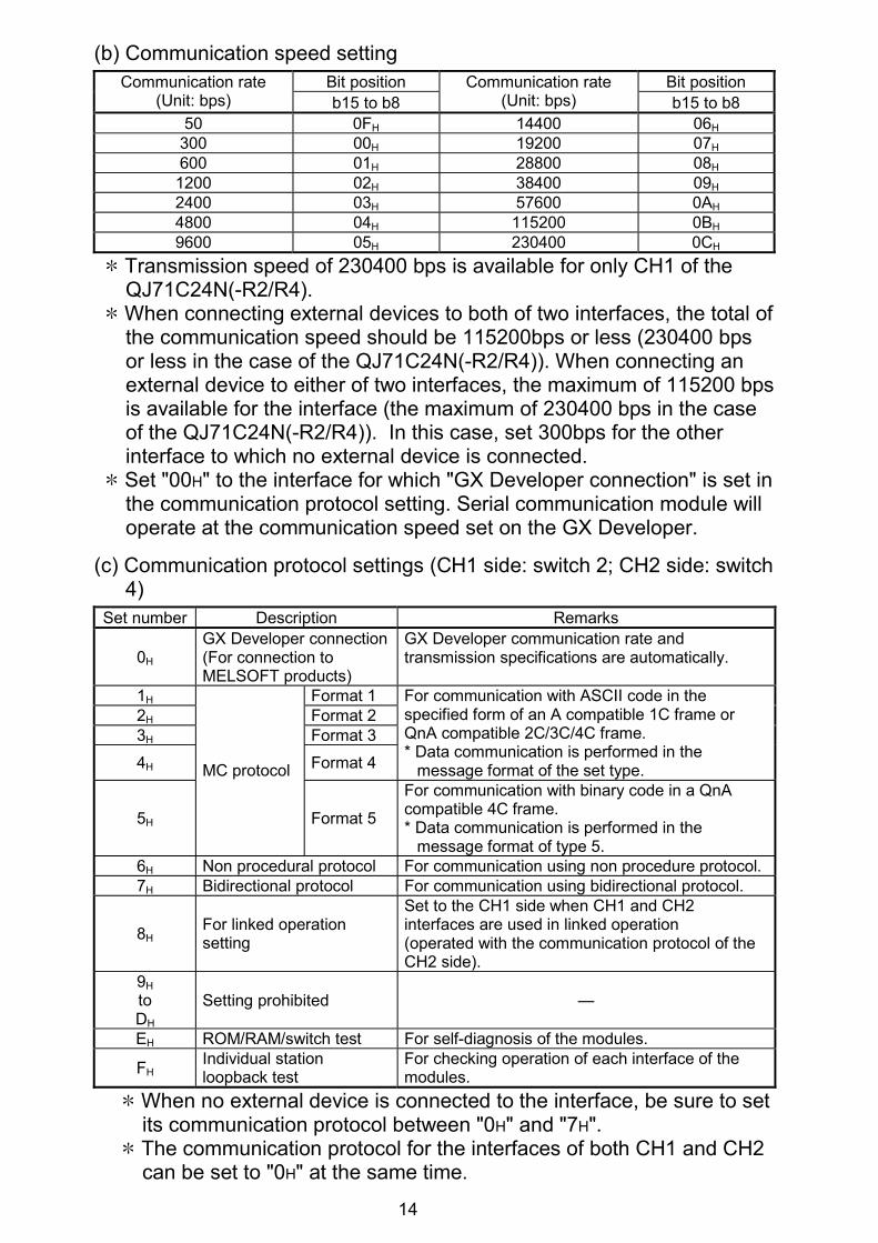
(b) Communication speed setting Bit position Bit position Communication rate
Transmission speed of 230400 bps is available for only CH1 of the QJ71C24N(-R2/R4).
When connecting external devices to both of two interfaces, the total of the communication speed should be 115200bps or less (230400 bps or less in the case of the QJ71C24N(-R2/R4)). When connecting an external device to either of two interfaces, the maximum of 115200 bps is available for the interface (the maximum of 230400 bps in the case of the QJ71C24N(-R2/R4)). In this case, set 300bps for the other interface to which no external device is connected.
Set "00H" to the interface for which "GX Developer connection" is set in the communication protocol setting. Serial communication module will operate at the communication speed set on the GX Developer.
0H GX Developer connection (For connection to MELSOFT products)
GX Developer communication rate and transmission specifications are automatically.
1H Format 1 2H Format 2 3H Format 3
4H Format 4
For communication with ASCII code in the specified form of an A compatible 1C frame or QnA compatible 2C/3C/4C frame. * Data communication is performed in the
message format of the set type.
5H
MC protocol
Format 5
For communication with binary code in a QnA compatible 4C frame. * Data communication is performed in the
message format of type 5. 6H Non procedural protocol For communication using non procedure protocol. 7H Bidirectional protocol For communication using bidirectional protocol.
8H For linked operation setting
Set to the CH1 side when CH1 and CH2 interfaces are used in linked operation (operated with the communication protocol of the CH2 side).
9H to DH
Setting prohibited —
EH ROM/RAM/switch test For self-diagnosis of the modules.
FH Individual station loopback test
For checking operation of each interface of the modules.
When no external device is connected to the interface, be sure to set its communication protocol between "0H" and "7H".
The communication protocol for the interfaces of both CH1 and CH2 can be set to "0H" at the same time.
15
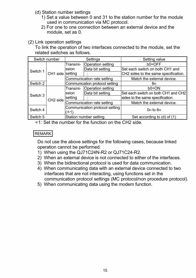
(d) Station number settings
1) Set a value between 0 and 31 to the station number for the module used in communication via MC protocol.
2) For one to one connection between an external device and the module, set as 0.
(2) Link operation settings
To link the operation of two interfaces connected to the module, set the related switches as follows.
Switch number Settings Setting value Operation setting b0=OFF Data bit setting
Transmi-ssion setting :
Set each switch on both CH1 and CH2 sides to the same specification. Switch 1
Communication rate setting Match the external device. Switch 2
CH1 side
Communication protocol setting 8H Operation setting b0=ON Data bit setting
Transmi-ssion setting :
Set each switch on both CH1 and CH2 sides to the same specification. Switch 3
Communication rate setting Match the external device.
Switch 4
CH2 side
Communication protocol setting ( 1) 0H to 6H
Switch 5 Station number setting Set according to (d) of (1) 1: Set the number for the function on the CH2 side.
REMARK
Do not use the above settings for the following cases, because linked operation cannot be performed. 1) When using the QJ71C24N-R2 or QJ71C24-R2. 2) When an external device is not connected to either of the interfaces. 3) When the bidirectional protocol is used for data communication. 4) When communicating data with an external device connected to two
interfaces that are not interacting, using functions set in the communication protocol settings (MC protocol/non procedure protocol).
5) When communicating data using the modem function.
16
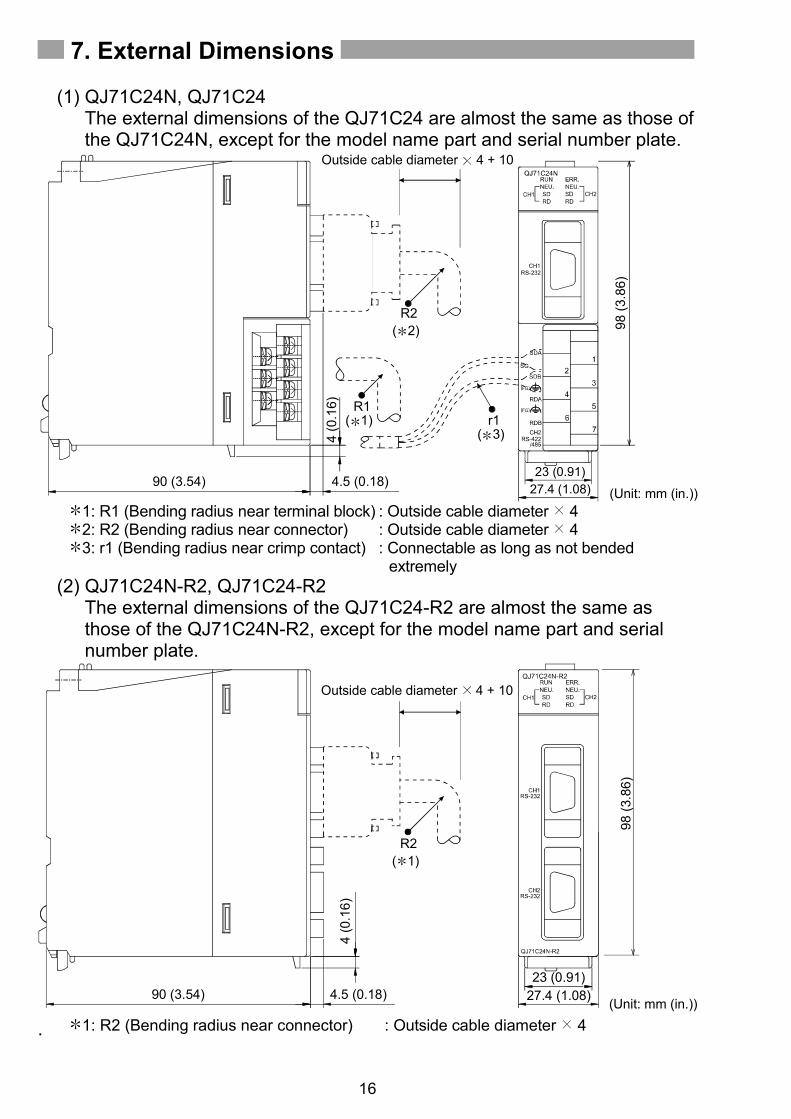
7. External Dimensions
(1) QJ71C24N, QJ71C24 The external dimensions of the QJ71C24 are almost the same as those of the QJ71C24N, except for the model name part and serial number plate.
R1( 1)
98 (3
.86)
r1( 3)
R2
Outside cable diameter 4 + 10
( 2)
(Unit: mm (in.))23 (0.91)
27.4 (1.08)
4 (0
.16)
90 (3.54) 4.5 (0.18)
1: R1 (Bending radius near terminal block) : Outside cable diameter 4 2: R2 (Bending radius near connector) : Outside cable diameter 4 3: r1 (Bending radius near crimp contact) : Connectable as long as not bended
extremely (2) QJ71C24N-R2, QJ71C24-R2
The external dimensions of the QJ71C24-R2 are almost the same as those of the QJ71C24N-R2, except for the model name part and serial number plate.
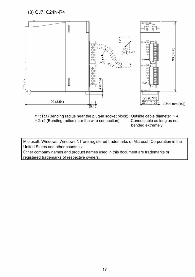
1: R3 (Bending radius near the plug-in socket block) : Outside cable diameter 4 2: r2 (Bending radius near the wire connection) : Connectable as long as not
bended extremely Microsoft, Windows, Windows NT are registered trademarks of Microsoft Corporation in the United States and other countries. Other company names and product names used in this document are trademarks or registered trademarks of respective owners.
Warranty Mitsubishi will not be held liable for damage caused by factors found not to be the cause of Mitsubishi; machine damage or lost profits caused by faults in the Mitsubishi products; damage, secondary damage, accident compensation caused by special factors unpredictable by Mitsubishi; damages to products other than Mitsubishi products; and to other duties.
For safe use This product has been manufactured as a general-purpose part for general industries, and has not been designed or manufactured to be incorporated in a device or system used in purposes related to human life.
Before using the product for special purposes such as nuclear power, electric power, aerospace, medicine or passenger movement vehicles, consult with Mitsubishi.
This product has been manufactured under strict quality control. However, when installing the product where major accidents or losses could occur if the product fails, install appropriate backup or failsafe functions in the system.
U.S.A Mitsubishi Electric Automation Inc. 500 Corporate Woods Parkway Vernon Hills, IL 60061, U.S.A. Tel : +1-847-478-2100Brazil MELCO-TEC Rep. Com.e Assessoria Tecnica Ltda. Rua Correia Dias, 184, Edificio Paraiso Trade Center-8 andar Paraiso, Sao Paulo, SP Brazil Tel : +55-11-5908-8331Germany Mitsubishi Electric Europe B.V. German Branch Gothaer Strasse 8 D-40880 Ratingen, GERMANY Tel : +49-2102-486-0U.K Mitsubishi Electric Europe B.V. UK Branch Travellers Lane, Hatfield, Hertfordshire., AL10 8XB, U.K. Tel : +44-1707-276100Italy Mitsubishi Electric Europe B.V. Italian Branch Centro Dir. Colleoni, Pal. Perseo-Ingr.2 Via Paracelso 12, I-20041 Agrate Brianza., Milano, Italy Tel : +39-039-60531Spain Mitsubishi Electric Europe B.V. Spanish Branch Carretera de Rubi 76-80, E-08190 Sant Cugat del Valles, Barcelona, Spain Tel : +34-93-565-3131France Mitsubishi Electric Europe B.V. French Branch 25, Boulevard des Bouvets, F-92741 Nanterre Cedex, France TEL: +33-1-5568-5568South Africa Circuit Breaker Industries Ltd. Private Bag 2016, ZA-1600 Isando, South Africa Tel : +27-11-928-2000
Hong Kong Mitsubishi Electric Automation (Hong Kong) Ltd. 10th Floor, Manulife Tower, 169 Electric Road, North Point, Hong Kong Tel : +852-2887-8870China Mitsubishi Electric Automation (Shanghai) Ltd. 4/F Zhi Fu Plazz, No.80 Xin Chang Road, Shanghai 200003, China Tel : +86-21-6120-0808Taiwan Setsuyo Enterprise Co., Ltd. 6F No.105 Wu-Kung 3rd.Rd, Wu-Ku Hsiang, Taipei Hsine, Taiwan Tel : +886-2-2299-2499Korea Mitsubishi Electric Automation Korea Co., Ltd. 1480-6, Gayang-dong, Gangseo-ku Seoul 157-200, Korea Tel : +82-2-3660-9552Singapore Mitsubishi Electric Asia Pte, Ltd. 307 Alexandra Road #05-01/02, Mitsubishi Electric Building, Singapore 159943 Tel : +65-6470-2460Thailand Mitsubishi Electric Automation (Thailand) Co., Ltd. Bang-Chan Industrial Estate No.111 Moo 4, Serithai Rd, T.Kannayao, A.Kannayao, Bangkok 10230 Thailand Tel : +66-2-517-1326Indonesia P.T. Autoteknindo Sumber Makmur Muara Karang Selatan, Block A/Utara No.1 Kav. No.11 Kawasan Industri Pergudangan Jakarta - Utara 14440, P.O.Box 5045 Jakarta, 11050 Indonesia Tel : +62-21-6630833India Messung Systems Pvt, Ltd. Electronic Sadan NO:III Unit No15, M.I.D.C Bhosari, Pune-411026, India Tel : +91-20-2712-3130Australia Mitsubishi Electric Australia Pty. Ltd. 348 Victoria Road, Rydalmere, N.S.W 2116, Australia Tel : +61-2-9684-7777
Country/Region Sales office/Tel
When exported from Japan, this manual does not require application to the Ministry of Economy, Trade and Industry for service transaction permission.
Specifications subject to change without notice.Printed in Japan on recycled paper.
HEAD OFFICE : TOKYO BUILDING, 2-7-3 MARUNOUCHI, CHIYODA-KU, TOKYO 100-8310, JAPANNAGOYA WORKS : 1-14, YADA-MINAMI 5-CHOME, HIGASHI-KU, NAGOYA, JAPAN