4096-757 Revision E May 13, 2009 ASSEMBLY MANUAL SERIES 1385 - 3.8M Rx/Tx ANTENNA SYSTEM GENERAL DYNAMICS SATCOM Technologies 1500 Prodelin Drive Newton NC 28658USA Phone 828-464-4141 www.gdsatcom.com
Transcript
4096-757 Revision E
May 13, 2009
ASSEMBLY MANUAL
SERIES 1385 - 3.8M Rx/Tx ANTENNA SYSTEM
GENERAL DYNAMICS SATCOM Technologies
1500 Prodelin Drive Newton NC 28658USA
Phone 828-464-4141 www.gdsatcom.com
General Dynamics Series 1385 - 3.8M Rx/Tx Antenna System C4 Systems 4096-757
ii
SERIES 1385 - 3.8M Rx/Tx ANTENNA SYSTEM
Legal Notice
General Dynamics’ drawings, sketches, computer programs, plans, specifications, technical data, prototype products, blueprints, photographs, instructions, diagrams, models, formulae, tables, engineering designs, diskettes, tapes, software, other electronic media (defined to include, but not be limited to, the system functional design, logic flow, algorithms, application programs, operating systems, software design implementation, tests, test results, operation, diagnosis, repair...) and/or documents (collectively "Proprietary Materials") are confidential and proprietary in nature and are considered by it to constitute "trade secrets" as defined by N.C. Gen. Stat. 66-152 (3)(a) and (b) of the North Carolina Uniform Trade Secrets Act, by the Uniform Trade Secrets Act and by any other states'/countries' Trade Secrets Acts regardless if some of the information or documents that were incorporated into such drawings, sketches, computer programs, plans, specifications, technical data, prototype products, blueprints, photographs, instructions, diagrams, models, formulae, tables, engineering designs, diskettes, tapes, software, other electronic media (defined to include, but not be limited to, the system functional design, logic flow, algorithms, application programs, operating systems, software design, implementation, tests, test results, operation, diagnosis repair...) and/or documents or other information that was incorporated into the Proprietary Materials came from a customer or third party and whether such Proprietary Materials do or do not constitute intellectual property, patent, trademark or copyright rights or material. THESE "PROPRIETARY MATERIALS" MAY NOT BE COPIED, REPRODUCED, DISCLOSED OR DISTRIBUTED IN WHOLE OR IN PART TO OTHER PARTIES EITHER VERBALLY OR IN WRITING WITHOUT PRIOR WRITTEN APPROVAL BEING OBTAINED FROM THE PRODELIN DOCUMENTATION SUPERVISOR OR A DULY AUTHORIZED REPRESENTATIVE.
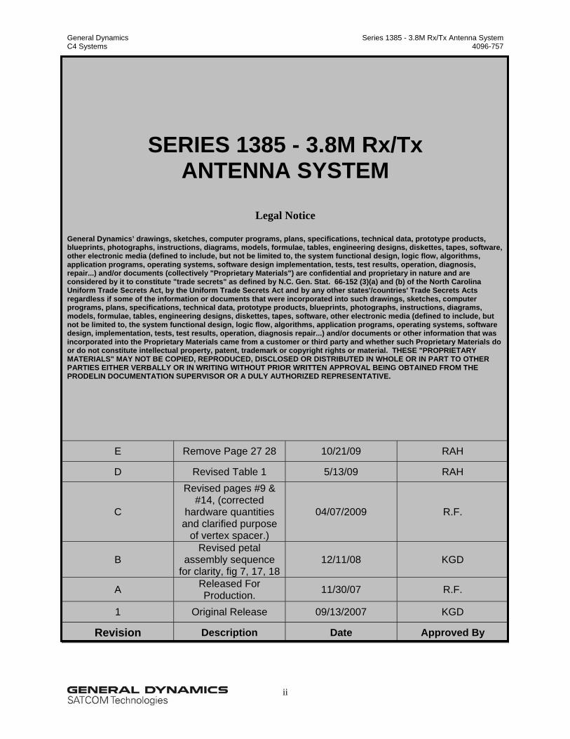
E Remove Page 27 28 10/21/09 RAH
D Revised Table 1 5/13/09 RAH
C
Revised pages #9 & #14, (corrected
hardware quantities and clarified purpose
of vertex spacer.)
04/07/2009 R.F.
B Revised petal
assembly sequence for clarity, fig 7, 17, 18
12/11/08 KGD
A Released For Production. 11/30/07 R.F.
1 Original Release 09/13/2007 KGD
Revision Description Date Approved By
General Dynamics Series 1385 - 3.8M Rx/Tx Antenna System C4 Systems 4096-757
iii
Table of Contents List of Illustrations …………………..…………………... iv
List of Tables …………………..…………………... vi
Preface …………………..…………………... vii
1. General Information …………………..…………………... 1
1.1. Warnings in this Manual …………………………................ 1
1.2. Unpacking and Inspection …………………………................ 2
Table II: Pedestal Mount Kit Part List ……………..………………….. 7
Table III: Reflector and Support Assembly Part List ……………..………………….. 9
Table IV: Feed Support Assembly Part List ……………..………………….. 18
Table V: Ku-Band Feed Part List ……………..………………….. 22
General Dynamics Series 1385 - 3.8M Rx/Tx Antenna System C4 Systems 4096-757
vii
Preface
Purpose This manual provides instructions for the installation of the 3.8-meter Ku-Band Antenna system. It covers topics that range from shipping inspection of the unassembled components to maintenance of the installed terminal. Audience This manual is a guide to an installer experienced in performing the various installation tasks. It shows the specific tasks for installing the 3.8-meter Antenna System. The following general tasks may be required of the installer:
• Use medium to large hand tools that require medium to heavy exertion of force.
• Assist erection team personnel in the lifting and locating of heavy components.
• Determine whether there are water pipes, electrical wiring, or gas lines hidden near where
they are installing the antenna.
• Route coaxial cable(s) through a foundation, walls, and/or floors.
• Ground the antenna and coaxial cable as recommended in the National Electrical Code
(published by the National Fire Protection Association, Batterymarch Park, Quincy, MA
02269).
The following are also possible users for this manual:
• Call Center personnel
• Call Center personnel trainers
Related Documentation The installer should reference all local building code regulations pertinent to the area in which they install the antenna. The installer should consult a local architect or civil engineer in determining the required foundation or other structural-related details for the specific site.
General Dynamics Series 1385 - 3.8M Rx/Tx Antenna System C4 Systems 4096-757
1
1. General Information
1.1. Warnings in this Manual
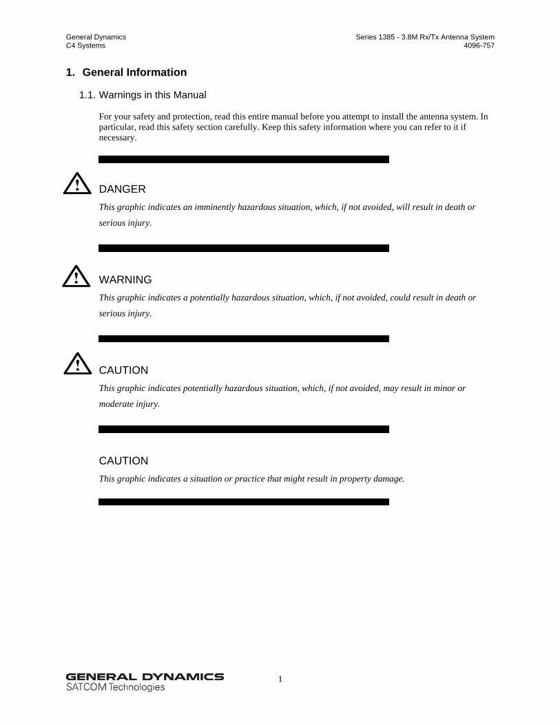
For your safety and protection, read this entire manual before you attempt to install the antenna system. In particular, read this safety section carefully. Keep this safety information where you can refer to it if necessary.
DANGER
This graphic indicates an imminently hazardous situation, which, if not avoided, will result in death or
serious injury.
WARNING This graphic indicates a potentially hazardous situation, which, if not avoided, could result in death or
serious injury.
CAUTION This graphic indicates potentially hazardous situation, which, if not avoided, may result in minor or
moderate injury.
CAUTION This graphic indicates a situation or practice that might result in property damage.
General Dynamics Series 1385 - 3.8M Rx/Tx Antenna System C4 Systems 4096-757
2
1.2. Unpacking and Inspection
The antenna containers should be unpacked and inspected at the earliest date to ensure that all material is included and is in good condition. Included with the material is a complete packing list for each major component.
CAUTION Do not drag the reflector support frame. The reflector attachment sleeves are factory set and you must not alter as this may result in poor antenna performance. Regarding freight damage, you should direct any materials, damaged while in transit to the freight carrier. He will instruct you on the matters regarding any freight damage claims. Regarding material, missing or damaged, you should direct any questions regarding missing or damaged materials that is not due to freight carrier to Prodelin's Customer Service Department at: General Dynamics C4 Systems 1500 Prodelin Drive Newton NC 28658 USA (828) 464-4141
1.3. Mechanical Installation Tools
During the installation, you should have convenient access to general-purpose hand and power tools. The following specific tools are required; however, site dependent materials and processes may require additional tools:
• Adjustable Crescent Wrench 10"
• Ratchet (3 / 8" and 1 / 2" Drive)
• 3" Wrench (socket, crescent or pipe) for 2" bolt
• Allen Wrench, 5/32"
• Screw Driver (standard and cross blade)
• Inclinometer and Compass
• Step Ladder
General Dynamics Series 1385 - 3.8M Rx/Tx Antenna System C4 Systems 4096-757
3
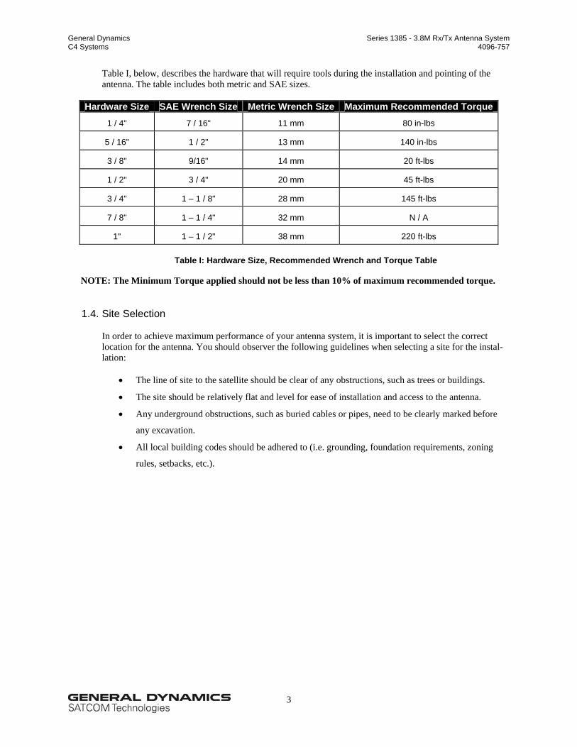
Table I, below, describes the hardware that will require tools during the installation and pointing of the antenna. The table includes both metric and SAE sizes.
Table I: Hardware Size, Recommended Wrench and Torque Table
NOTE: The Minimum Torque applied should not be less than 10% of maximum recommended torque.
1.4. Site Selection
In order to achieve maximum performance of your antenna system, it is important to select the correct location for the antenna. You should observer the following guidelines when selecting a site for the instal-lation:
• The line of site to the satellite should be clear of any obstructions, such as trees or buildings.
• The site should be relatively flat and level for ease of installation and access to the antenna.
• Any underground obstructions, such as buried cables or pipes, need to be clearly marked before
any excavation.
• All local building codes should be adhered to (i.e. grounding, foundation requirements, zoning
rules, setbacks, etc.).
General Dynamics Series 1385 - 3.8M Rx/Tx Antenna System C4 Systems 4096-757
4
2. Suggested Mast and Foundations
WARNING Due to the wide variety of soil conditions, Prodelin Corporation does not warrant that any particular design or size of foundation is appropriate for any locality or earth station installation. It is the responsibility of the installer/user to determine if it meets the site/locality requirements. If there is any doubt, have it checked by an architect or structural engineer.
2.1. In-Ground Mast Mount
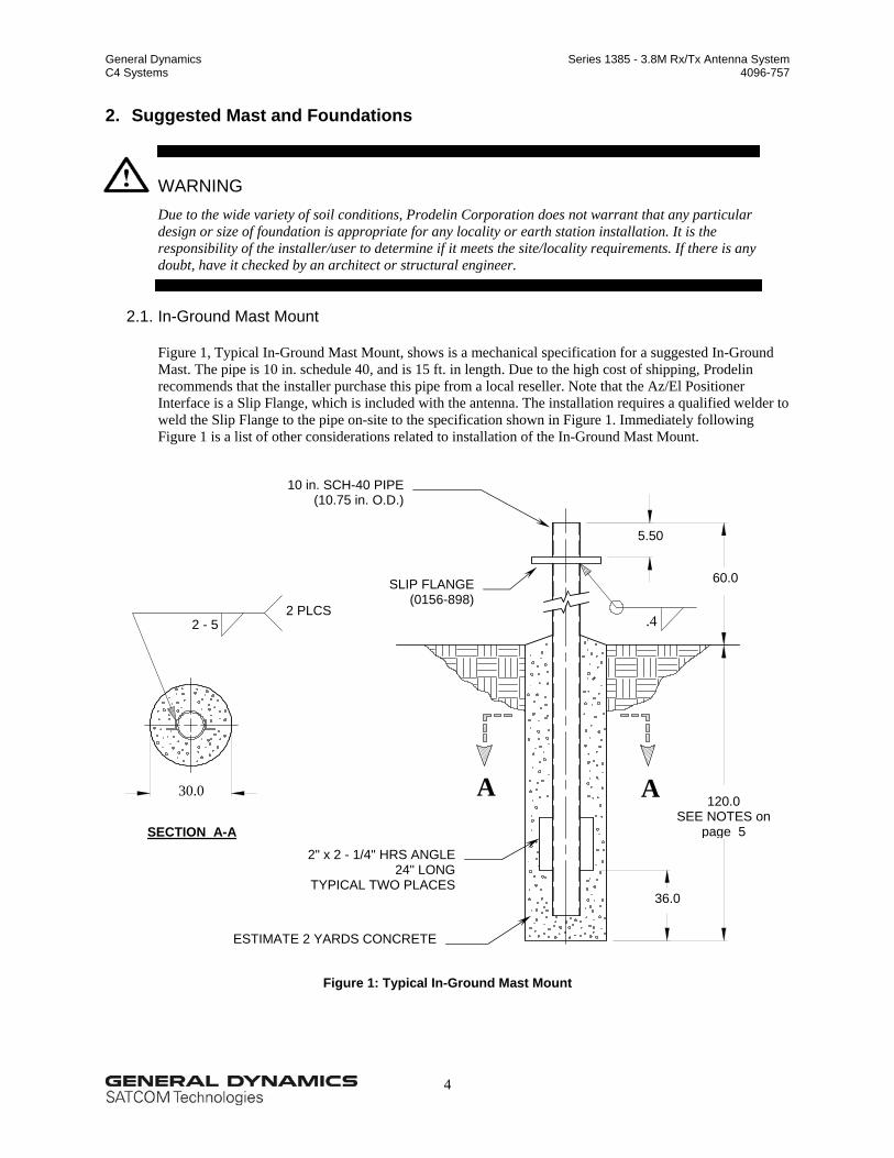
Figure 1, Typical In-Ground Mast Mount, shows is a mechanical specification for a suggested In-Ground Mast. The pipe is 10 in. schedule 40, and is 15 ft. in length. Due to the high cost of shipping, Prodelin recommends that the installer purchase this pipe from a local reseller. Note that the Az/El Positioner Interface is a Slip Flange, which is included with the antenna. The installation requires a qualified welder to weld the Slip Flange to the pipe on-site to the specification shown in Figure 1. Immediately following Figure 1 is a list of other considerations related to installation of the In-Ground Mast Mount.
Figure 1: Typical In-Ground Mast Mount
5.50
60.0
.4 2 - 5 2 PLCS
A A
36.0
120.0 SEE NOTES on
page 5
30.0
SECTION A-A 2" x 2 - 1/4" HRS ANGLE
24" LONGTYPICAL TWO PLACES
SLIP FLANGE(0156-898)
10 in. SCH-40 PIPE(10.75 in. O.D.)
ESTIMATE 2 YARDS CONCRETE
General Dynamics Series 1385 - 3.8M Rx/Tx Antenna System C4 Systems 4096-757
5
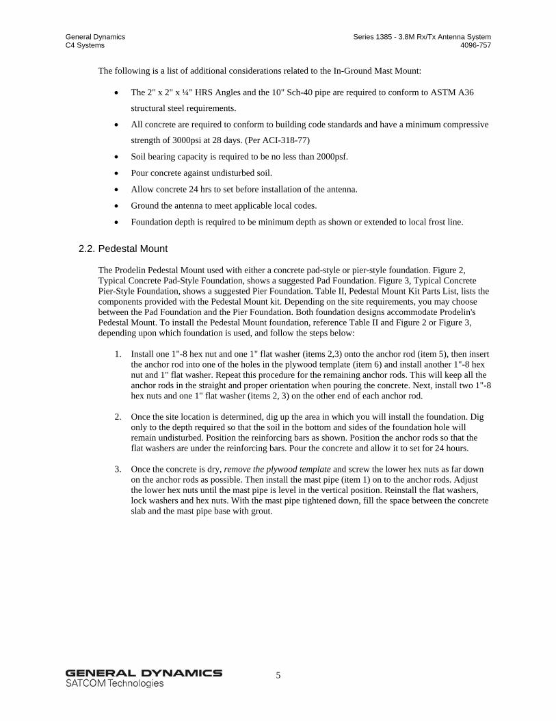
The following is a list of additional considerations related to the In-Ground Mast Mount:
• The 2" x 2" x ¼" HRS Angles and the 10" Sch-40 pipe are required to conform to ASTM A36
structural steel requirements.
• All concrete are required to conform to building code standards and have a minimum compressive
strength of 3000psi at 28 days. (Per ACI-318-77)
• Soil bearing capacity is required to be no less than 2000psf.
• Pour concrete against undisturbed soil.
• Allow concrete 24 hrs to set before installation of the antenna.
• Ground the antenna to meet applicable local codes.
• Foundation depth is required to be minimum depth as shown or extended to local frost line.
2.2. Pedestal Mount
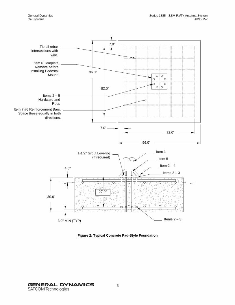
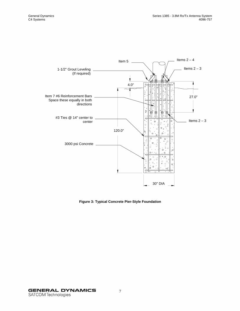
The Prodelin Pedestal Mount used with either a concrete pad-style or pier-style foundation. Figure 2, Typical Concrete Pad-Style Foundation, shows a suggested Pad Foundation. Figure 3, Typical Concrete Pier-Style Foundation, shows a suggested Pier Foundation. Table II, Pedestal Mount Kit Parts List, lists the components provided with the Pedestal Mount kit. Depending on the site requirements, you may choose between the Pad Foundation and the Pier Foundation. Both foundation designs accommodate Prodelin's Pedestal Mount. To install the Pedestal Mount foundation, reference Table II and Figure 2 or Figure 3, depending upon which foundation is used, and follow the steps below:
1. Install one 1"-8 hex nut and one 1" flat washer (items 2,3) onto the anchor rod (item 5), then insert
the anchor rod into one of the holes in the plywood template (item 6) and install another 1"-8 hex nut and 1" flat washer. Repeat this procedure for the remaining anchor rods. This will keep all the anchor rods in the straight and proper orientation when pouring the concrete. Next, install two 1"-8 hex nuts and one 1" flat washer (items 2, 3) on the other end of each anchor rod.
2. Once the site location is determined, dig up the area in which you will install the foundation. Dig
only to the depth required so that the soil in the bottom and sides of the foundation hole will remain undisturbed. Position the reinforcing bars as shown. Position the anchor rods so that the flat washers are under the reinforcing bars. Pour the concrete and allow it to set for 24 hours.
3. Once the concrete is dry, remove the plywood template and screw the lower hex nuts as far down
on the anchor rods as possible. Then install the mast pipe (item 1) on to the anchor rods. Adjust the lower hex nuts until the mast pipe is level in the vertical position. Reinstall the flat washers, lock washers and hex nuts. With the mast pipe tightened down, fill the space between the concrete slab and the mast pipe base with grout.
General Dynamics Series 1385 - 3.8M Rx/Tx Antenna System C4 Systems 4096-757
6
Figure 2: Typical Concrete Pad-Style Foundation
27.0"
4.0"
30.0"
7.0"
96.0"
82.0"
7.0"
96.0"
82.0"
Item 6 Template Remove before
installing PedestalMount.
Items 2 – 5Hardware and
Rods
Item 7 #6 Reinforcement Bars.Space these equally in both
directions.
Tie all rebar intersections with
wire.
3.0" MIN (TYP)
Item 2 – 4
Items 2 – 3
1-1/2" Grout Leveling(If required)
Item 1
Item 5
Items 2 – 3
General Dynamics Series 1385 - 3.8M Rx/Tx Antenna System C4 Systems 4096-757
7
Figure 3: Typical Concrete Pier-Style Foundation
30" DIA
1-1/2" Grout Leveling(If required)
Items 2 – 3
Items 2 – 4 Item 5
Items 2 – 3 #3 Ties @ 14" center to
center
3000 psi Concrete
120.0"
27.0"
4.0"
Item 7 #6 Reinforcement BarsSpace these equally in both
directions
General Dynamics Series 1385 - 3.8M Rx/Tx Antenna System C4 Systems 4096-757
8
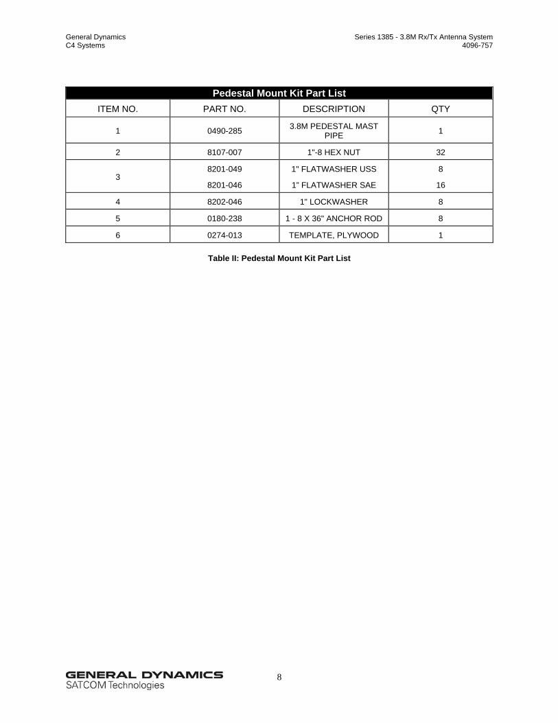
Pedestal Mount Kit Part List ITEM NO. PART NO. DESCRIPTION QTY
1 0490-285 3.8M PEDESTAL MAST PIPE 1
2 8107-007 1"-8 HEX NUT 32
3 8201-049
8201-046
1" FLATWASHER USS
1” FLATWASHER SAE
8
16
4 8202-046 1" LOCKWASHER 8
5 0180-238 1 - 8 X 36" ANCHOR ROD 8
6 0274-013 TEMPLATE, PLYWOOD 1
Table II: Pedestal Mount Kit Part List
General Dynamics Series 1385 - 3.8M Rx/Tx Antenna System C4 Systems 4096-757
9
3. Reflector and Support Assembly
3.1. Parts List
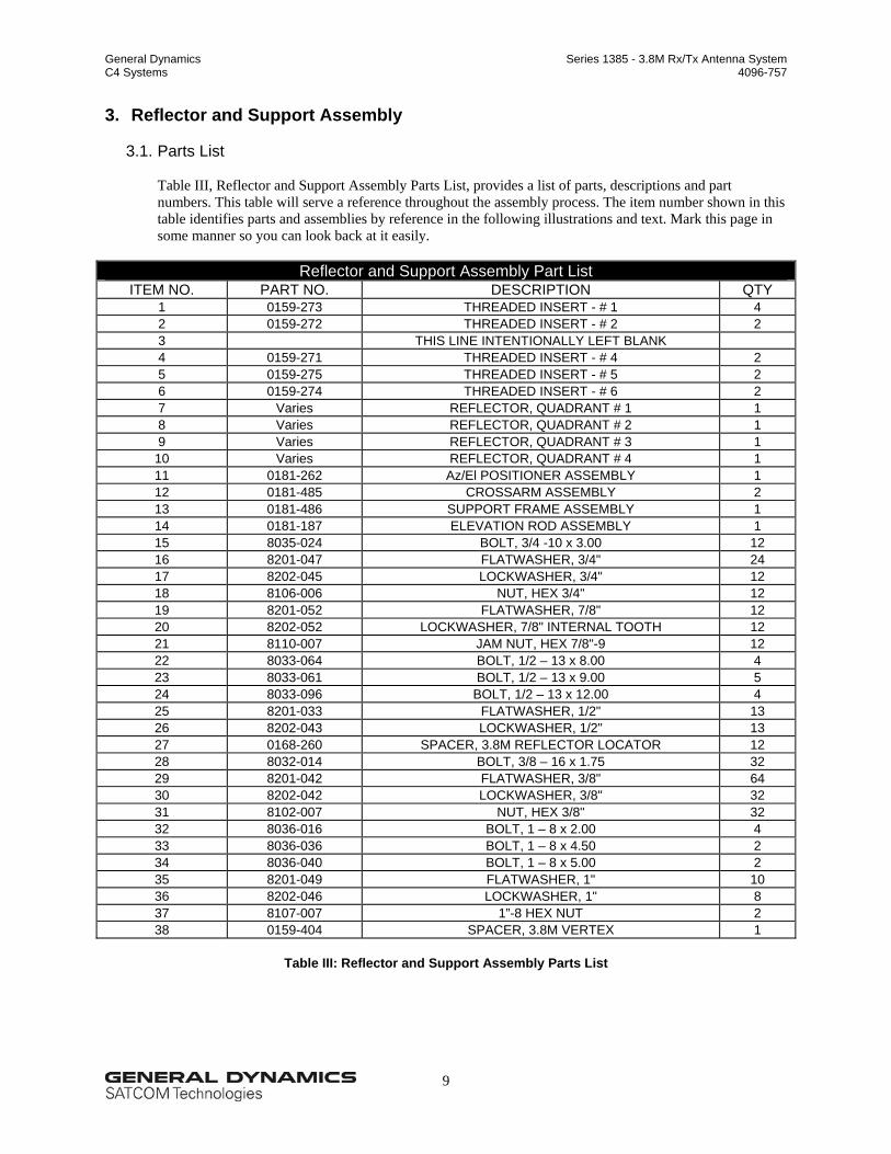
Table III, Reflector and Support Assembly Parts List, provides a list of parts, descriptions and part numbers. This table will serve a reference throughout the assembly process. The item number shown in this table identifies parts and assemblies by reference in the following illustrations and text. Mark this page in some manner so you can look back at it easily.
Reflector and Support Assembly Part List ITEM NO. PART NO. DESCRIPTION QTY
Table III: Reflector and Support Assembly Parts List
General Dynamics Series 1385 - 3.8M Rx/Tx Antenna System C4 Systems 4096-757
10
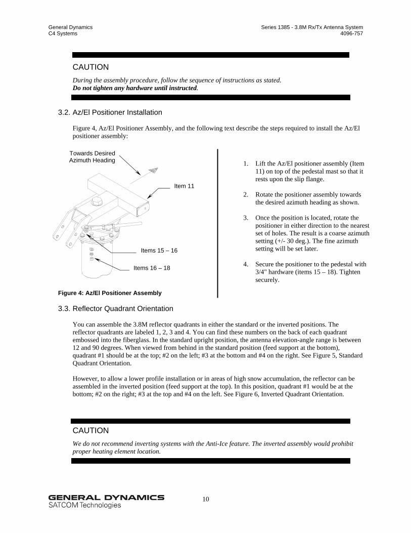
CAUTION During the assembly procedure, follow the sequence of instructions as stated. Do not tighten any hardware until instructed.
3.2. Az/El Positioner Installation
Figure 4, Az/El Positioner Assembly, and the following text describe the steps required to install the Az/El positioner assembly:
Figure 4: Az/El Positioner Assembly
3.3. Reflector Quadrant Orientation
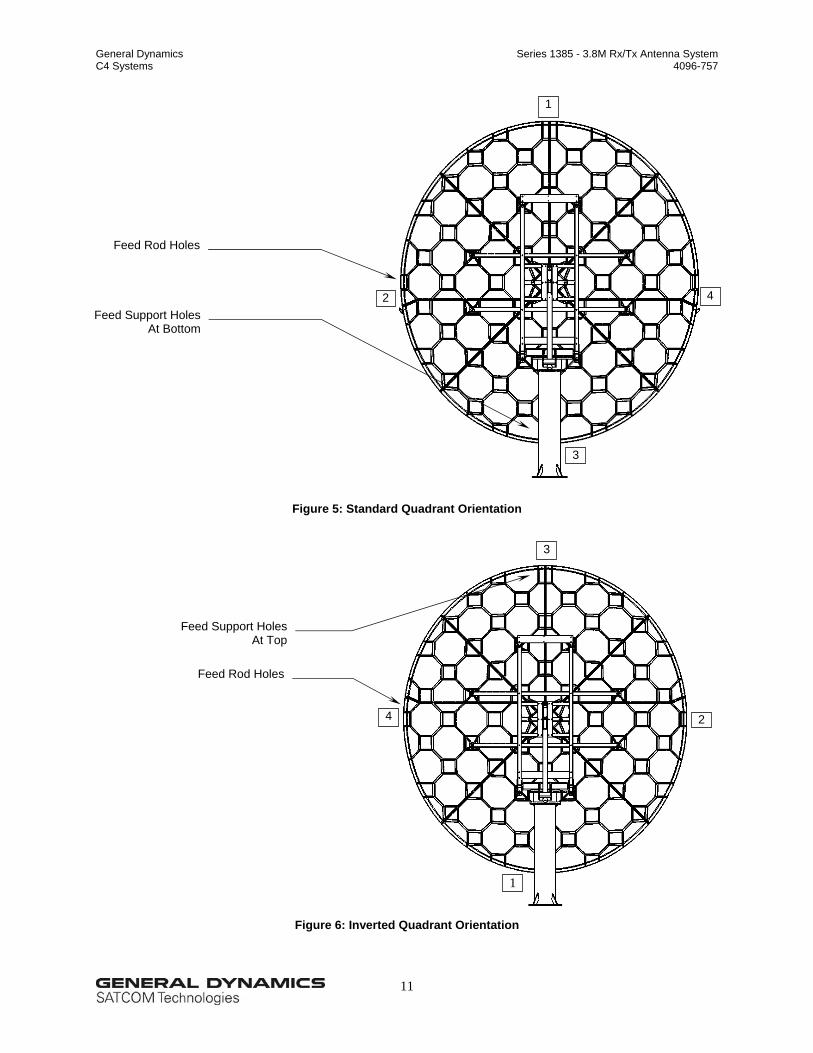
You can assemble the 3.8M reflector quadrants in either the standard or the inverted positions. The reflector quadrants are labeled 1, 2, 3 and 4. You can find these numbers on the back of each quadrant embossed into the fiberglass. In the standard upright position, the antenna elevation-angle range is between 12 and 90 degrees. When viewed from behind in the standard position (feed support at the bottom), quadrant #1 should be at the top; #2 on the left; #3 at the bottom and #4 on the right. See Figure 5, Standard Quadrant Orientation. However, to allow a lower profile installation or in areas of high snow accumulation, the reflector can be assembled in the inverted position (feed support at the top). In this position, quadrant #1 would be at the bottom; #2 on the right; #3 at the top and #4 on the left. See Figure 6, Inverted Quadrant Orientation.
CAUTION We do not recommend inverting systems with the Anti-Ice feature. The inverted assembly would prohibit proper heating element location.
Items 16 – 18
Items 15 – 16
Towards DesiredAzimuth Heading
Item 11
1. Lift the Az/El positioner assembly (Item 11) on top of the pedestal mast so that it rests upon the slip flange.
2. Rotate the positioner assembly towards
the desired azimuth heading as shown.
3. Once the position is located, rotate the positioner in either direction to the nearest set of holes. The result is a coarse azimuth setting (+/- 30 deg.). The fine azimuth setting will be set later.
4. Secure the positioner to the pedestal with
3/4" hardware (items 15 – 18). Tighten securely.
General Dynamics Series 1385 - 3.8M Rx/Tx Antenna System C4 Systems 4096-757
11
Figure 5: Standard Quadrant Orientation
Figure 6: Inverted Quadrant Orientation
1
4 2
3
1
4 2
3
Feed Rod Holes
Feed Support HolesAt Bottom
Feed Support HolesAt Top
Feed Rod Holes
General Dynamics Series 1385 - 3.8M Rx/Tx Antenna System C4 Systems 4096-757
12
3.4. Reflector Support Assembly
The reflector support is the metal frame that supports the reflector, attaches the reflector to the Az/El Positioner, and thus allows adjustment of the antenna elevation angle. The following figures and text describe the steps necessary to assemble the reflector support.
CAUTION The reflector support frame includes a precision alignment feature. Do not drop or drag the frame during the installation process. Do not attempt to adjust the round tube spacers in the frame assembly, as these are factory pre-set. If these spacers are loose or damaged, or there is any obvious damage to the frame, then you must obtain replacement parts for a successful installation.
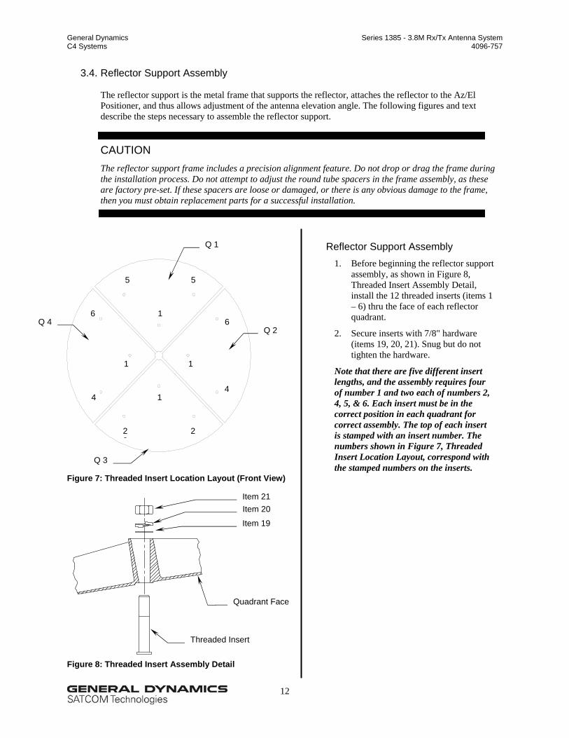
Reflector Support Assembly 1. Before beginning the reflector support
assembly, as shown in Figure 8, Threaded Insert Assembly Detail, install the 12 threaded inserts (items 1 – 6) thru the face of each reflector quadrant.
2. Secure inserts with 7/8" hardware (items 19, 20, 21). Snug but do not tighten the hardware.
Note that there are five different insert lengths, and the assembly requires four of number 1 and two each of numbers 2, 4, 5, & 6. Each insert must be in the correct position in each quadrant for correct assembly. The top of each insert is stamped with an insert number. The numbers shown in Figure 7, Threaded Insert Location Layout, correspond with the stamped numbers on the inserts.
Q 1
Q 2 Q 4
Q 3
5
6
1
1
5
6
1
1 4
22
4
2
Item 21
Threaded Insert
Item 20
Item 19
Quadrant Face
General Dynamics Series 1385 - 3.8M Rx/Tx Antenna System C4 Systems 4096-757
13
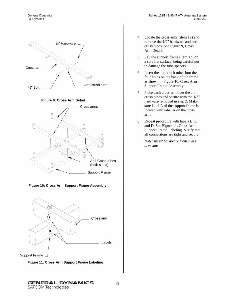
Figure 9: Cross Arm Detail
Figure 10: Cross Arm Support Frame Assembly
Figure 11: Cross Arm Support Frame Labeling
½" Hardware
Anti-crush tube ½" Bolt
Cross arm
Anti-Crush tubes (both sides)
Support Frame
Cross arms
Labels
Cross arm
Support Frame
4. Locate the cross arms (item 12) and remove the 1/2" hardware and anti-crush tubes. See Figure 9, Cross Arm Detail.
5. Lay the support frame (item 13) on a safe flat surface, being careful not to damage the tube spacers.
6. Insert the anti-crush tubes into the four holes on the back of the frame as shown in Figure 10, Cross Arm Support Frame Assembly.
7. Place each cross arm over the anti-crush tubes and secure with the 1/2" hardware removed in step 2. Make sure label A of the support frame is located with label A on the cross arm.
8. Repeat procedure with labels B, C and D. See Figure 11, Cross Arm Support Frame Labeling. Verify that all connections are tight and secure.
Note: Insert hardware from cross arm side.
General Dynamics Series 1385 - 3.8M Rx/Tx Antenna System C4 Systems 4096-757
14
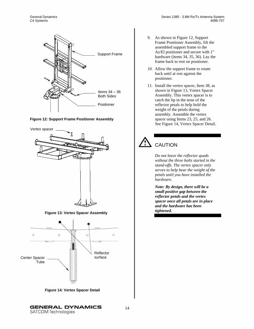
Figure 12: Support Frame Positioner Assembly
Figure 13: Vertex Spacer Assembly
Figure 14: Vertex Spacer Detail
Vertex spacer
Support Frame
Items 34 – 36 Both Sides
Positioner
Reflector surface Center Spacer
Tube
9. As shown in Figure 12, Support Frame Positioner Assembly, lift the assembled support frame to the Az/El positioner and secure with 1" hardware (items 34, 35, 36). Lay the frame back to rest on positioner.
10. Allow the support frame to rotate back until at rest against the positioner.
11. Install the vertex spacer, Item 38, as shown in Figure 13, Vertex Spacer Assembly. This vertex spacer is to catch the lip in the nose of the reflector petals to help hold the weight of the petals during assembly. Assemble the vertex spacer using Items 23, 25, and 26. See Figure 14, Vertex Spacer Detail.
CAUTION
Do not leave the reflector quads without the three bolts started in the stand-offs. The vertex spacer only serves to help bear the weight of the petals until you have installed the hardware.
Note: By design, there will be a small positive gap between the reflector petals and the vertex spacer once all petals are in place and the hardware has been tightened.
General Dynamics Series 1385 - 3.8M Rx/Tx Antenna System C4 Systems 4096-757
15
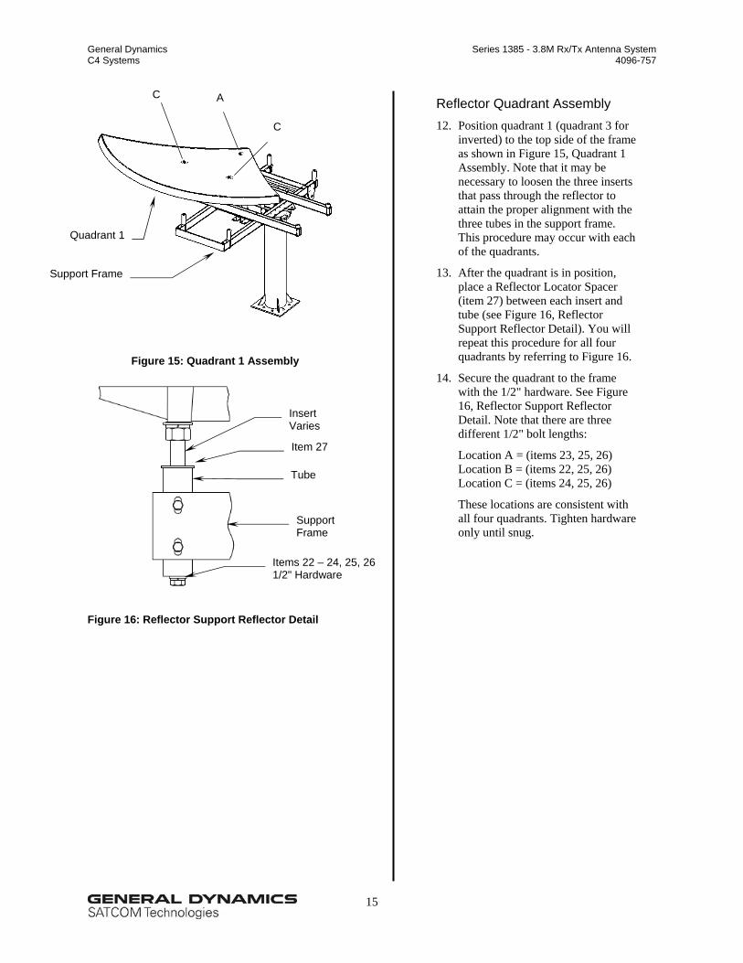
Figure 15: Quadrant 1 Assembly
Figure 16: Reflector Support Reflector Detail
A
C
C
Quadrant 1
Support Frame
Reflector Quadrant Assembly 12. Position quadrant 1 (quadrant 3 for
inverted) to the top side of the frame as shown in Figure 15, Quadrant 1 Assembly. Note that it may be necessary to loosen the three inserts that pass through the reflector to attain the proper alignment with the three tubes in the support frame. This procedure may occur with each of the quadrants.
13. After the quadrant is in position, place a Reflector Locator Spacer (item 27) between each insert and tube (see Figure 16, Reflector Support Reflector Detail). You will repeat this procedure for all four quadrants by referring to Figure 16.
14. Secure the quadrant to the frame with the 1/2" hardware. See Figure 16, Reflector Support Reflector Detail. Note that there are three different 1/2" bolt lengths:
Location A = (items 23, 25, 26) Location B = (items 22, 25, 26) Location C = (items 24, 25, 26)
These locations are consistent with all four quadrants. Tighten hardware only until snug.
Items 22 – 24, 25, 26
1/2" Hardware
Item 27
Insert Varies
Tube
Support Frame
General Dynamics Series 1385 - 3.8M Rx/Tx Antenna System C4 Systems 4096-757
16
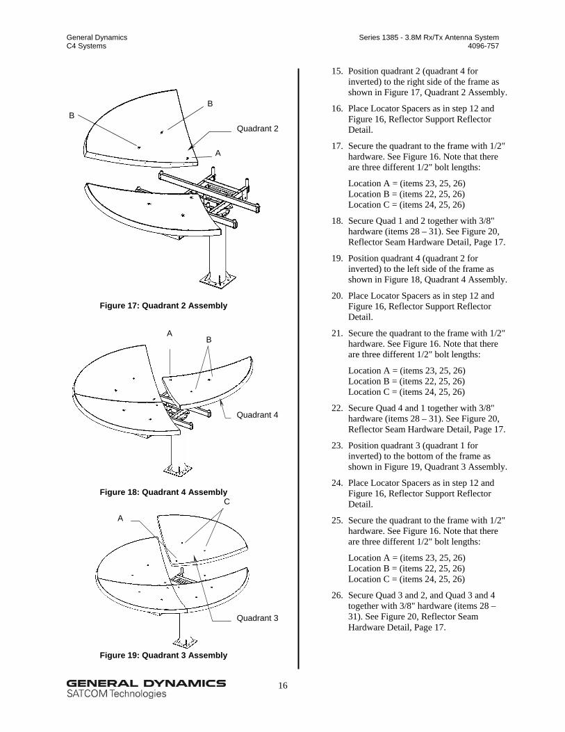
Figure 17: Quadrant 2 Assembly
Figure 18: Quadrant 4 Assembly
Figure 19: Quadrant 3 Assembly
Quadrant 2
A
B B
B A
Quadrant 4
C
A
15. Position quadrant 2 (quadrant 4 for inverted) to the right side of the frame as shown in Figure 17, Quadrant 2 Assembly.
16. Place Locator Spacers as in step 12 and Figure 16, Reflector Support Reflector Detail.
17. Secure the quadrant to the frame with 1/2" hardware. See Figure 16. Note that there are three different 1/2" bolt lengths:
Location A = (items 23, 25, 26) Location B = (items 22, 25, 26) Location C = (items 24, 25, 26)
18. Secure Quad 1 and 2 together with 3/8" hardware (items 28 – 31). See Figure 20, Reflector Seam Hardware Detail, Page 17.
19. Position quadrant 4 (quadrant 2 for inverted) to the left side of the frame as shown in Figure 18, Quadrant 4 Assembly.
20. Place Locator Spacers as in step 12 and Figure 16, Reflector Support Reflector Detail.
21. Secure the quadrant to the frame with 1/2" hardware. See Figure 16. Note that there are three different 1/2" bolt lengths:
Location A = (items 23, 25, 26) Location B = (items 22, 25, 26) Location C = (items 24, 25, 26)
22. Secure Quad 4 and 1 together with 3/8" hardware (items 28 – 31). See Figure 20, Reflector Seam Hardware Detail, Page 17.
23. Position quadrant 3 (quadrant 1 for inverted) to the bottom of the frame as shown in Figure 19, Quadrant 3 Assembly.
24. Place Locator Spacers as in step 12 and Figure 16, Reflector Support Reflector Detail.
25. Secure the quadrant to the frame with 1/2" hardware. See Figure 16. Note that there are three different 1/2" bolt lengths:
Location A = (items 23, 25, 26) Location B = (items 22, 25, 26) Location C = (items 24, 25, 26)
26. Secure Quad 3 and 2, and Quad 3 and 4 together with 3/8" hardware (items 28 – 31). See Figure 20, Reflector Seam Hardware Detail, Page 17.
Quadrant 3
General Dynamics Series 1385 - 3.8M Rx/Tx Antenna System C4 Systems 4096-757
17
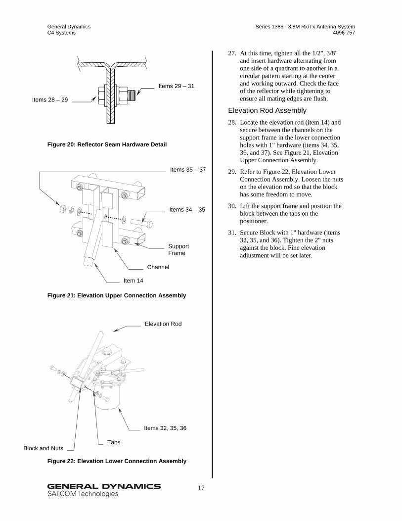
Figure 20: Reflector Seam Hardware Detail
Figure 21: Elevation Upper Connection Assembly
Figure 22: Elevation Lower Connection Assembly
Items 28 – 29
Items 29 – 31
27. At this time, tighten all the 1/2", 3/8" and insert hardware alternating from one side of a quadrant to another in a circular pattern starting at the center and working outward. Check the face of the reflector while tightening to ensure all mating edges are flush.
Elevation Rod Assembly 28. Locate the elevation rod (item 14) and
secure between the channels on the support frame in the lower connection holes with 1" hardware (items 34, 35, 36, and 37). See Figure 21, Elevation Upper Connection Assembly.
29. Refer to Figure 22, Elevation Lower Connection Assembly. Loosen the nuts on the elevation rod so that the block has some freedom to move.
30. Lift the support frame and position the block between the tabs on the positioner.
31. Secure Block with 1" hardware (items 32, 35, and 36). Tighten the 2" nuts against the block. Fine elevation adjustment will be set later.
Items 34 – 35
Channel
Item 14
Support Frame
Elevation Rod
Block and NutsTabs
Items 32, 35, 36
Items 35 – 37
General Dynamics Series 1385 - 3.8M Rx/Tx Antenna System C4 Systems 4096-757
18
4. Feed Support Assembly
4.1. Parts List
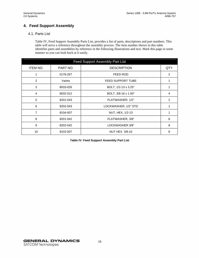
Table IV, Feed Support Assembly Parts List, provides a list of parts, descriptions and part numbers. This table will serve a reference throughout the assembly process. The item number shown in this table identifies parts and assemblies by reference in the following illustrations and text. Mark this page in some manner so you can look back at it easily.
Feed Support Assembly Part List
ITEM NO. PART NO. DESCRIPTION QTY
1 0176-257 FEED ROD 2
2 Varies FEED SUPPORT TUBE 1
3 8033-026 BOLT, 1/2-13 x 3.25" 1
4 8032-012 BOLT, 3/8-16 x 1.50" 4
5 8201-043 FLATWASHER, 1/2" 2
6 8202-043 LOCKWASHER, 1/2" STD 1
7 8104-007 NUT, HEX, 1/2-13 1
8 8201-042 FLATWASHER, 3/8” 8
9 8202-042 LOCKWASHER 3/8” 8
10 8102-007 NUT HEX 3/8-16 8
Table IV: Feed Support Assembly Part List
General Dynamics Series 1385 - 3.8M Rx/Tx Antenna System C4 Systems 4096-757
19
CAUTION During the assembly procedure, follow the sequence of instructions as stated. Do not tighten any hardware until instructed.
4.2. Feed Support Installation
The following text and figures describe the steps required to install the Feed Support. These are general instructions for a typical feed support. If your system is supplied with specific instructions for a particular feed support, refer to those instructions at this time.
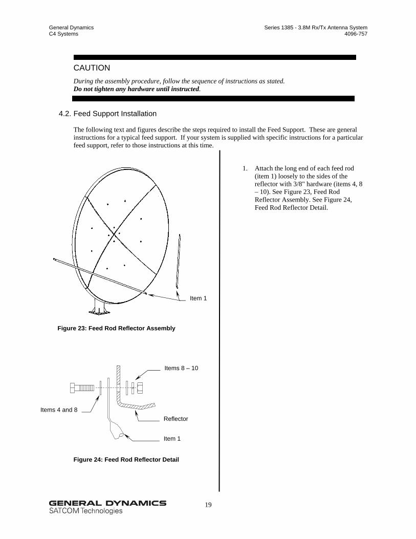
Figure 23: Feed Rod Reflector Assembly
Figure 24: Feed Rod Reflector Detail
Item 1
Item 1
Reflector
Items 8 – 10
Items 4 and 8
1. Attach the long end of each feed rod (item 1) loosely to the sides of the reflector with 3/8" hardware (items 4, 8 – 10). See Figure 23, Feed Rod Reflector Assembly. See Figure 24, Feed Rod Reflector Detail.
General Dynamics Series 1385 - 3.8M Rx/Tx Antenna System C4 Systems 4096-757
20
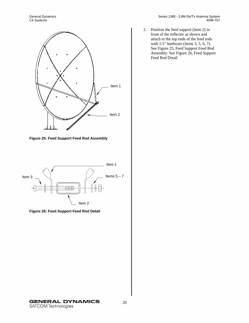
Figure 25: Feed Support Feed Rod Assembly
Figure 26: Feed Support Feed Rod Detail
Item 2
Item 1
Item 1
Item 2
Items 5 – 7
2. Position the feed support (item 2) in front of the reflector as shown and attach to the top ends of the feed rods with 1/2" hardware (items 3, 5, 6, 7). See Figure 25, Feed Support Feed Rod Assembly. See Figure 26, Feed Support Feed Rod Detail
Item 3
General Dynamics Series 1385 - 3.8M Rx/Tx Antenna System C4 Systems 4096-757
21
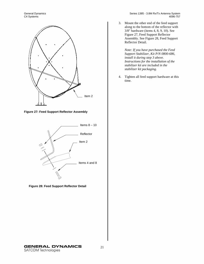
Figure 27: Feed Support Reflector Assembly
Figure 28: Feed Support Reflector Detail
Item 2
Items 8 – 10
Reflector
Item 2
Items 4 and 8
3. Mount the other end of the feed support along to the bottom of the reflector with 3/8" hardware (items 4, 8, 9, 10). See Figure 27, Feed Support Reflector Assembly. See Figure 28, Feed Support Reflector Detail.
Note: If you have purchased the Feed Support Stabilizer, Kit P/N 0800-686, install it during step 3 above. Instructions for the installation of the stabilizer kit are included in the stabilizer kit packaging.
4. Tighten all feed support hardware at this
time.
General Dynamics Series 1385 - 3.8M Rx/Tx Antenna System C4 Systems 4096-757
22
4.3. Ku-Band Feed Assembly
For C-Band feed installation. (See Manual 4096-772) The following text and figures describe the steps required to install a Ku-Band Feed. If your system is provided with something other than a ku-band feed refer to the specific installation instructions supplied with that feed assembly at this time. General Dynamic’s 3.8-meter Ku-Band Rx/Tx Antenna System is available with a variety of Ku-Band feed assemblies. General Dynamics provides only the feed horn and hardware kit with the base antenna. If you have purchased the feed assembly from General Dynamics, the feed support packaging contains additional instructions specific to the feed assembly. 4.3.1. Parts List
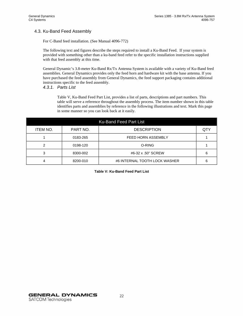
Table V, Ku-Band Feed Part List, provides a list of parts, descriptions and part numbers. This table will serve a reference throughout the assembly process. The item number shown in this table identifies parts and assemblies by reference in the following illustrations and text. Mark this page in some manner so you can look back at it easily.
Ku-Band Feed Part List
ITEM NO. PART NO. DESCRIPTION QTY
1 0183-265 FEED HORN ASSEMBLY 1
2 0198-120 O-RING 1
3 8300-002 #6-32 x .50” SCREW 6
4 8200-010 #6 INTERNAL TOOTH LOCK WASHER 6
Table V: Ku-Band Feed Part List
General Dynamics Series 1385 - 3.8M Rx/Tx Antenna System C4 Systems 4096-757
23
4.3.2. Feed Assembly (Ku-Band)
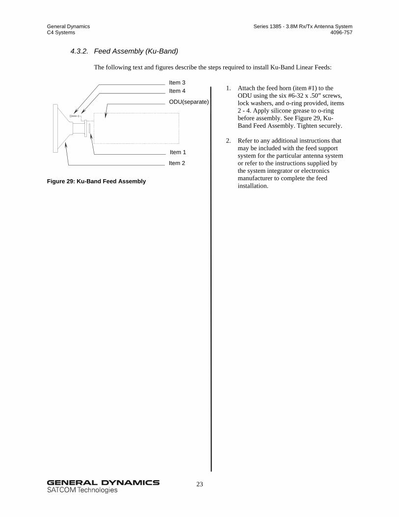
The following text and figures describe the steps required to install Ku-Band Linear Feeds:
Figure 29: Ku-Band Feed Assembly
Item 3
Item 2
Item 4
Item 1
1. Attach the feed horn (item #1) to the ODU using the six #6-32 x .50” screws, lock washers, and o-ring provided, items 2 - 4. Apply silicone grease to o-ring before assembly. See Figure 29, Ku-Band Feed Assembly. Tighten securely.
2. Refer to any additional instructions that
may be included with the feed support system for the particular antenna system or refer to the instructions supplied by the system integrator or electronics manufacturer to complete the feed installation.
ODU(separate)
General Dynamics Series 1385 - 3.8M Rx/Tx Antenna System C4 Systems 4096-757
24
5. Antenna Pointing
5.1. Alignment to the Satellite
General Dynamics recommends that a trained or experienced installer align the 3.8-meter Az/El to the satellite orbital arc. We intend these instructions in section 5.1 to be an overview of the alignment procedure.
5.2. Initial Alignment
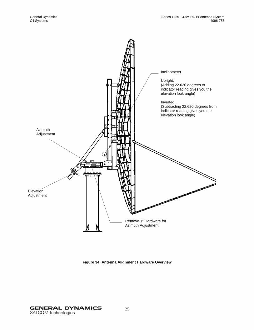
The 3.8 meter offset reflector has a 22.62-degree elevation offset look angle. Therefore, when the reflector aperture is perpendicular to the ground, the antenna look-angle is 22.62 degrees in elevation. The following steps summarize how to align the antenna initially: 1. Raise the antenna by turning the 2" nuts on the elevation rod assembly. 2. After the correct elevation angle is set, rotate the antenna in the azimuth plane by loosening the 2" nut
on top of the positioner and removing the 1" hardware (4 places) in the positioner plate, refer to Figure 34, Antenna Alignment Hardware Overview.
3. At this time, rotate the antenna in azimuth by turning the 1" nuts located at the azimuth adjustment
tube. Rotate the antenna in the azimuth plane until you acquire a signal. 4. Peak the antenna by fine adjustments made in both the elevation and the azimuth. 5. Adjust polarization by rotating the feed assembly in its mounting bracket. 6. Re-install the 1" hardware in the Az/El positioner from step 2 and tighten all adjustment hardware
securely.
General Dynamics Series 1385 - 3.8M Rx/Tx Antenna System C4 Systems 4096-757
25
Figure 34: Antenna Alignment Hardware Overview
Inclinometer Upright: (Adding 22.620 degrees to indicator reading gives you the elevation look angle) Inverted (Subtracting 22.620 degrees from indicator reading gives you the elevation look angle)
Remove 1" Hardware for Azimuth Adjustment
Elevation Adjustment
Azimuth Adjustment
General Dynamics Series 1385 - 3.8M Rx/Tx Antenna System C4 Systems 4096-757
26
6. Maintenance
6.1. Maintenance Overview
After installation, the antenna requires only periodic inspection. You should anticipate that maintenance, if required, would be minimal and easily handled by a local or in house maintenance staff. The materials used in the construction of this Earth Station Antenna virtually eliminate any maintenance repairs.
6.2. Periodic Inspection
We suggest that you perform a periodic inspection at least every six months. Note that after any very severe weather condition, you should inspect the antenna to determine if foreign objects have caused damage or if conditions have exceeded survival specifications. During a periodic inspection, inspect the following items:
Check all bolted locations – all bolts should be tight.
Check all structural members – repair or replace if damaged.
Check the foundation anchor bolts – they should be secure and have no signs of potential failure.
Check for corrosion – observe the reflector and metal structure.
6.3. Reflector
Prodelin's reflector does not require any maintenance. The composite construction of the reflector is virtually impervious to damage caused by weather or other atmospheric conditions.
It is only necessary to inspect for any physical damage done by vandalism or very severe weather
conditions. Should you detect any damage be detected to a portion of the reflector, contact the Customer Service
Department at Prodelin regarding reflector repair or replacement.
6.4. Mount and Reflector Support Structure
The mount and reflector support structure supplied with this antenna is of steel construction and has a galvanized finish. The hardware has a zinc finish and a topcoat for corrosion protection.
If inspection shows any sign of structural failure, repair or replace the damaged mount members. Repair any corrosion on steel members with a cold, zinc-rich, galvanizing paint.
6.5. Feed and Feed Support
Make sure the feed support tube and feed rod hardware is secure, and the feed and radio mounting bolts are tight.
Make sure the feed horn window is intact to prevent moisture from collecting inside the feed horn. Replace