18
Series 20 Axial Piston Pumps Technical Information
Series 20Axial Piston Pumps
Technical Information
2 L1003621 • Rev AB • Jan 2011
Series 20 Axial Piston PumpsTechnical Information
Sauer-Danfoss a world leader in hydraulic power systems has developed a family of axial piston pumps.
Sauer-Danfoss axial piston variable displacement pumps are of swash plate design with variable flow capability suitable for hydrostatic transmissions with closed loop circuit.Tilting the swash plate to the opposite side of the neutral or zero displacement position reverses flow direction.
Sauer-Danfoss axial piston variable displacement pumps are well engineered and easy to handle.The full-length shaft with a highly efficient tapered roller bearing arrangement offers a high loading capacity for external radical forces.The hydro-mechanical servo displacement control maintains the selected swash plate position and hence pumps displacement.Upon release of the control handle, the swash plate automatically returns to zero position and the flow reduces to zero.High case pressures can be achieved without leakage even at the lowest temperatures by using suitable shaft seals.The servo valve arrangement offers the facility to incorporate function regulators and remote control systems.Axial piston units are designed for easy servicing. Complete dismantling and reassembly can be carried out with standard hand tools, and all components or sub-assemblies are replaceable.Axial piston variable displacement pumps of the Sauer-Danfoss pattern are made by licensed producers worldwide, providing consistent service and fully interchangeable parts.
• Industrial• Mining• Transit Mixer• Utility Vehicles
Introduction
Description
Typical markets
General Description
© 2011 Sauer-Danfoss. All rights reserved.
Sauer-Danfoss accepts no responsibility for possible errors in catalogs, brochures and other printed material. Sauer -Danfoss reserves the right to alter its products without prior notice. This also applies to products already ordered provided that such alterations can be made without affecting agreed specifications. All trademarks in this material are properties of their respective owners. Sauer-Danfoss, the Sauer-Danfoss logotype, the Sauer-Danfoss S-icon, PLUS+1™, What really matters is inside® and Know-How in Motion™ are trademarks of the Sauer-Danfoss Group.
Front cover illustrations: F005 104, F000 248, F000 150, F000 249
3L1003621 • Rev AB • Jan 2011
Series 20 Axial Piston PumpsTechnical InformationContents
General Description
Technical Specification
Dimensions – Frame Size 070 and 089
Dimensions – Frame Size 334
Axial Piston Variable Displacement Pump ............................................................................................ 4Pump and Motor Circuit Description ...................................................................................................... 5Pump circuit schematic ................................................................................................................................ 5
Technical Parameters .................................................................................................................................... 6Design ........................................................................................................................................................... 6Type of mounting ..................................................................................................................................... 6Pipe connections ...................................................................................................................................... 6Direction of rotation ................................................................................................................................ 6Installation position ................................................................................................................................. 6External drain fluid loss .......................................................................................................................... 6
Hydraulic Parameters .................................................................................................................................... 7System pressure range, input p1 .......................................................................................................... 7System pressure range, output p2 ....................................................................................................... 7Case pressure ............................................................................................................................................. 7Hydraulic fluids .......................................................................................................................................... 7Temperature range ................................................................................................................................... 7Viscosity range ........................................................................................................................................... 7Filtration ....................................................................................................................................................... 7Shaft load ..................................................................................................................................................... 7
Hydraulic Parameters .................................................................................................................................... 8Determination of Nominal Pump Sizes .................................................................................................. 8
Based on SI units/Based on US units .................................................................................................. 8Servo Displacement Control (linear response) .................................................................................... 9
Pump flow direction ................................................................................................................................ 9Reversing time .........................................................................................................................................10Reset time ..................................................................................................................................................11Changing reversing and reset time ..................................................................................................11
Configuration PS, displacement control VML 1 .................................................................................12Configuration AA 010, displacement control VML 1 .......................................................................14
Configuration PS, displacement control VML 1 .................................................................................15Configuration AA 010, displacement control VML 1 .......................................................................17
4 L1003621 • Rev AB • Jan 2011
Series 20 Axial Piston PumpsTechnical Information
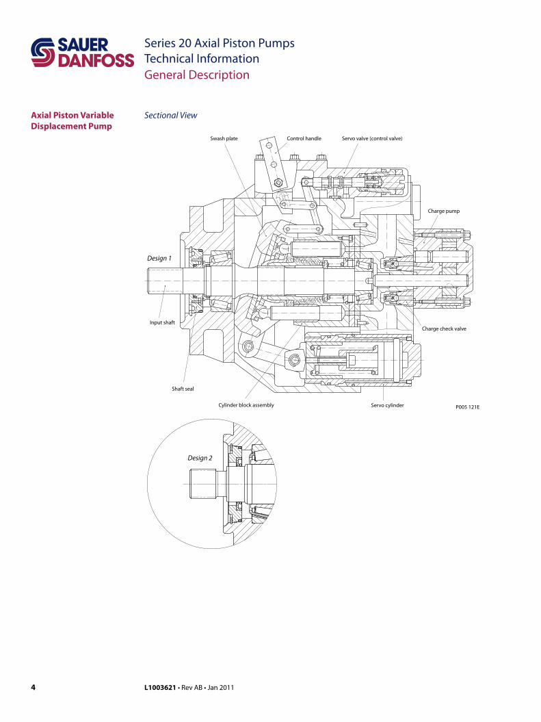
Sectional ViewAxial Piston Variable Displacement Pump
Input shaft
Design 1
Design 2
Swash plate Control handle Servo valve (control valve)
Charge pump
Charge check valve
Servo cylinderCylinder block assembly
Shaft seal
P005 121E
General Description
5L1003621 • Rev AB • Jan 2011
Series 20 Axial Piston PumpsTechnical Information
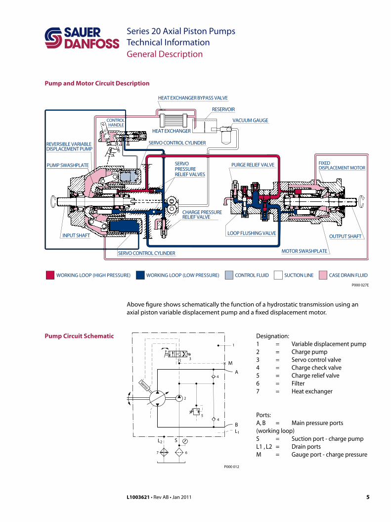
Pump and Motor Circuit Description
Designation:1 = Variable displacement pump2 = Charge pump3 = Servo control valve4 = Charge check valve5 = Charge relief valve6 = Filter7 = Heat exchanger
Ports:A, B = Main pressure ports (working loop)S = Suction port - charge pumpL1 , L2 = Drain portsM = Gauge port - charge pressure
HEAT EXCHANGER BYPASS VALVE
RESERVOIR
VACUUM GAUGE
HEAT EXCHANGER
OUTPUT SHAFT
MOTOR SWASHPLATE
FIXEDDISPLACEMENT MOTOR
LOOP FLUSHING VALVE
PURGE RELIEF VALVE
CHARGE PRESSURERELIEF VALVE
SERVOPRESSURERELIEF VALVES
SERVO CONTROL CYLINDER
SERVO CONTROL CYLINDER
PUMP SWASHPLATE
REVERSIBLE VARIABLEDISPLACEMENT PUMP
CONTROL HANDLE
INPUT SHAFT
WORKING LOOP (LOW PRESSURE) SUCTION LINE CASE DRAIN FLUIDCONTROL FLUIDWORKING LOOP (HIGH PRESSURE)
P000 027E
5
3
Servo
2
4
4
M
A
BL1
L2 S
6
1
7
P000 012
Pump Circuit Schematic
Above figure shows schematically the function of a hydrostatic transmission using an axial piston variable displacement pump and a fixed displacement motor.
General Description
6 L1003621 • Rev AB • Jan 2011
Series 20 Axial Piston PumpsTechnical InformationTechnical Specification
Technical Parameters DesignAxial piston pump of swash plate design, with variable displacement.
Type of mountingSAE four bolt flanges.
Pipe connectionsMain pressure ports: SAE split flangeRemaining ports: SAE O-ring boss
Direction of rotationClockwise or counterclockwise (viewing from the input shaft).
Installation positionOptional; pump housing must be always filled with hydraulic fluid.
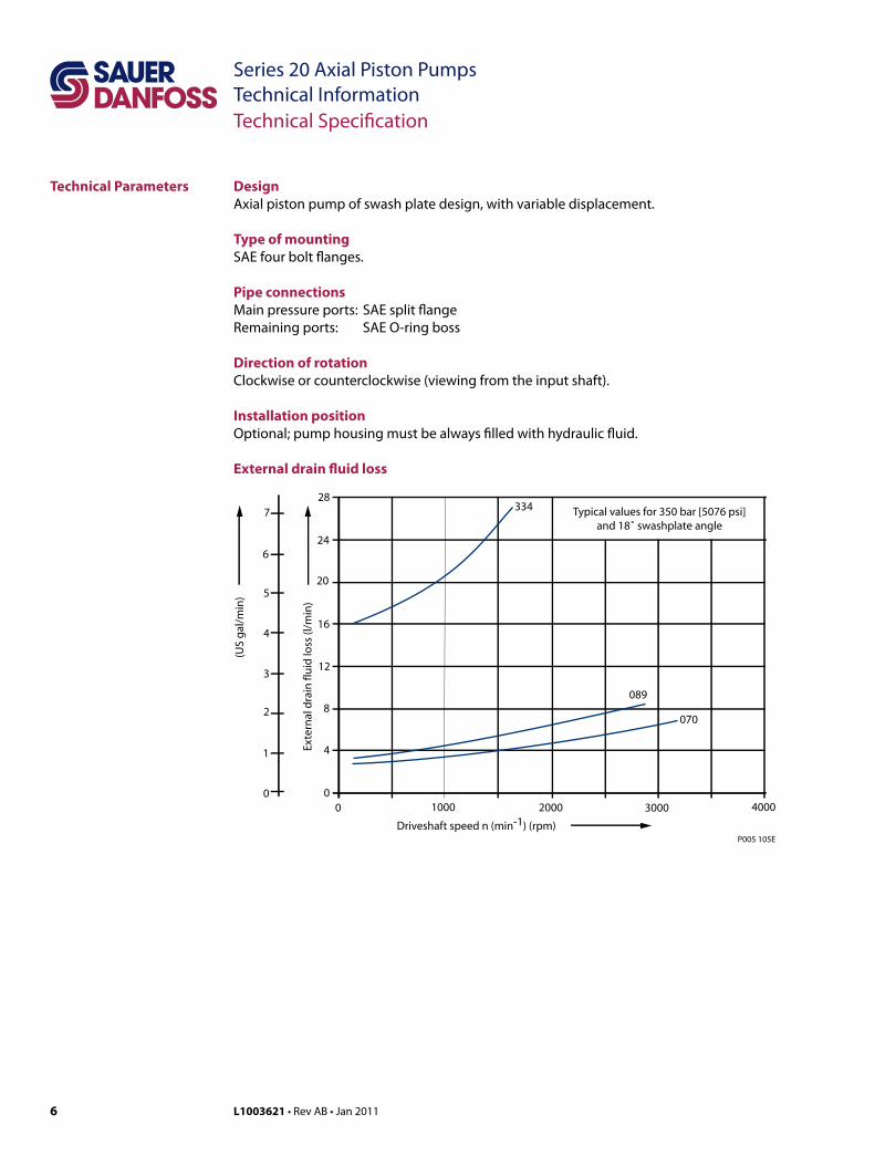
External drain fluid loss
P005 105E
Driveshaft speed n (min-1) (rpm)
Exte
rnal
dra
in fl
uid
loss
(l/m
in)
Typical values for 350 bar [5076 psi]and 18˚ swashplate angle
1000 2000 3000 400000
4
8
12
16
20
24
28334
089
070
(US
gal
/min
)
0
1
2
3
4
5
6
7
7L1003621 • Rev AB • Jan 2011
Series 20 Axial Piston PumpsTechnical InformationTechnical Specification
System pressure range, input p1
Variable displacement pump:Charge pressure nominal: 13 bar [189 psi] above case pressureCharge pressure minimum: 8 bar [116 psi], intermittent only
Charge pump input pressure:Min. allowable pressure, continuous = 0.75 bar [10.9 psi] absoluteMin. allowable pressure, intermittent = 0.50 bar [7.3 psi] absolute (for cold start)
Charge pump output pressure:Max. operating pressure = 35 bar [508 psi] above case pressure
System pressure range, output p2
Pressure on port A or B: Max. operating pressure ∆p = 420 bar [6092 psi] Max. high pressure setting ∆p = 460 bar1 [6672 psi] 1only with POR-valve
Case pressureMax. rated pressure = 2.5 bar [36.3 psi]Intermittent = 5.0 bar [72.5 psi]
Hydraulic fluidsRefer to Sauer-Danfoss publications Hydraulic Fluids and Lubricants, 520L0463 and Experience with Biodegradable Hydraulic Fluids, 520L0465.
Temperature rangeϑmin = - 40 °C [- 40 °F]ϑmax = 95 °C [203 °F]
Viscosity rangeνmin = 7 mm2/s [49 SUS*]νmax = 1000 mm2/s [4630 SUS*] (intermittent cold start)Recommended viscosity range: 12 - 60 mm2/s [66 - 280 SUS*]
*SUS (Saybolt Universal Second)
FiltrationRequired cleanliness level: ISO 4406 - 1999 Code 22/18/13 or better. Refer to Sauer-Danfoss publication Hydraulic Fluids and Lubricants, 520L0463 and Design Guideline for Hydraulic Fluid Cleanliness, 520L0467.
Shaft loadThe pump will accept radial and axial loads on its shaft, the maximum capacity being determined by direction and point of application of the load. Please contact your Sauer-Danfoss representative.
Hydraulic Parameters
8 L1003621 • Rev AB • Jan 2011
Series 20 Axial Piston PumpsTechnical InformationTechnical Specification
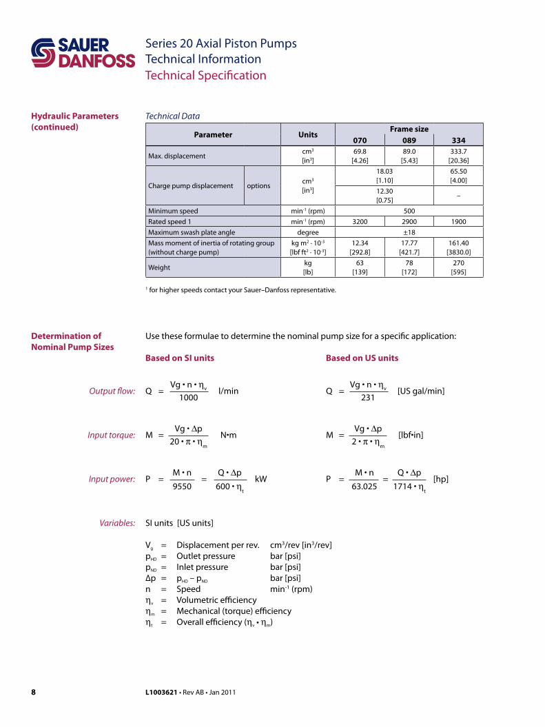
Technical Data
Parameter UnitsFrame size
070 089 334
Max. displacementcm3
[in3]69.8
[4.26]89.0
[5.43]333.7
[20.36]
Charge pump displacement optionscm3
[in3]
18.03[1.10]
65.50[4.00]
12.30[0.75]
–
Minimum speed min-1 (rpm) 500Rated speed 1 min-1 (rpm) 3200 2900 1900Maximum swash plate angle degree ±18Mass moment of inertia of rotating group(without charge pump)
kg m2 · 10-3
[lbf ft2 · 10-3]12.34
[292.8]17.77
[421.7]161.40
[3830.0]
Weightkg[lb]
63[139]
78[172]
270[595]
1 for higher speeds contact your Sauer–Danfoss representative.
Hydraulic Parameters(continued)
Use these formulae to determine the nominal pump size for a specific application:
Based on SI units Based on US units
Vg • n • ηvQ = l/min 1000
Vg • ∆pM = N•m 20 • π • η
m
M • n Q • ∆pP = = kW 9550 600 • η
t
SI units [US units]
Vg = Displacement per rev. cm3/rev [in3/rev]pHD = Outlet pressure bar [psi]pND = Inlet pressure bar [psi]∆p = pHD – pND bar [psi]n = Speed min-1 (rpm)ηv = Volumetric efficiencyηm = Mechanical (torque) efficiencyηt = Overall efficiency (ηv • ηm)
Vg • n • ηvQ = [US gal/min] 231
Vg • ∆pM = [lbf•in] 2 • π • η
m
M • n Q • ∆pP = = [hp] 63.025 1714 • η
t
Output flow:
Input torque:
Input power:
Variables:
Determination of Nominal Pump Sizes
9L1003621 • Rev AB • Jan 2011
Series 20 Axial Piston PumpsTechnical Information
40
60
20
20
40
60
69.8
69.8
25.7 25.7
Vg [cm3]
∀ α [˚]
Vg [cm3]
∀ α [˚]
23.5 20
20 23.215
15 10
10
5
5
3
3
0.5
0.5
P000 016
40
60
80
20
20
40
60
80
89.0
89.0
29.5 29.5
Vg [cm3]
∀ α [˚]
Vg [cm3]
∀ α [˚]
27 25 20
20 272515
15 10
10
5
5
3
3
0.5
0.5
P000 017
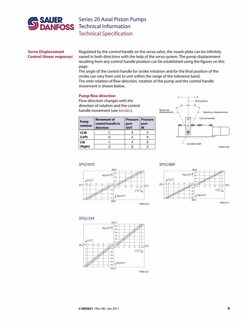
Regulated by the control handle on the servo valve, the swash plate can be infinitely varied in both directions with the help of the servo system. The pump displacement resulting from any control handle position can be established using the figures on this page.The angle of the control handle for stroke initiation and for the final position of the stroke can vary from unit to unit within the range of the tolerance band. The inter-relation of flow direction, rotation of the pump and the control handle movement is shown below.
Technical Specification
Servo Displacement Control (linear response)
Null position
Maximumdisplacement Maximum displacement
Serrated shaft
Control handle
C D
α α
P000 013E
50
100
150
200
250
300
50
150
200
250
300
100
333.7
333.7
29.2 29.2
Vg [cm3]
∀ α [˚]
Vg [cm3]
∀ α [˚]
26.7 25 20
20 25 26.215
15 10
10
5
5
3
3
0.5
0.5
P000 021
SPV2/070
SPV2/334
SPV2/089
Pump rotation
Movement of control handle in direction
Pressure portOUT
Pressure portIN
CCW (Left)
C B AD A B
CW (Right)
C A BD B A
Pump flow directionFlow direction changes with the direction of rotation and the control handle movement (see besides).
10 L1003621 • Rev AB • Jan 2011
Series 20 Axial Piston PumpsTechnical Information
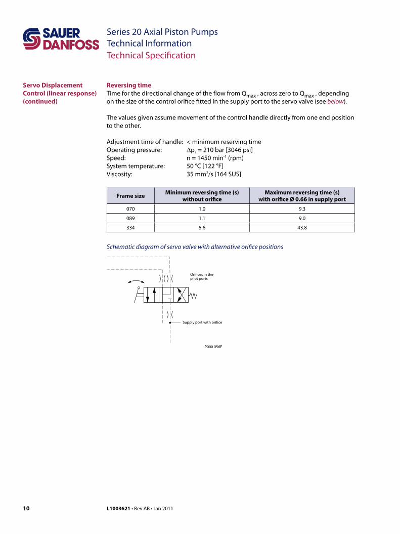
Reversing timeTime for the directional change of the flow from Qmax , across zero to Qmax , depending on the size of the control orifice fitted in the supply port to the servo valve (see below).
The values given assume movement of the control handle directly from one end position to the other.
Adjustment time of handle: < minimum reserving time Operating pressure: ∆p2 = 210 bar [3046 psi]Speed: n = 1450 min-1 (rpm)System temperature: 50 °C [122 °F]Viscosity: 35 mm2/s [164 SUS]
Frame size Minimum reversing time (s)without orifice
Maximum reversing time (s)with orifice Ø 0.66 in supply port
070 1.0 9.3
089 1.1 9.0
334 5.6 43.8
Schematic diagram of servo valve with alternative orifice positions
Technical Specification
Servo Displacement Control (linear response)(continued)
Supply port with orifice
Orifices in thepilot ports
P000 056E
11L1003621 • Rev AB • Jan 2011
Series 20 Axial Piston PumpsTechnical Information
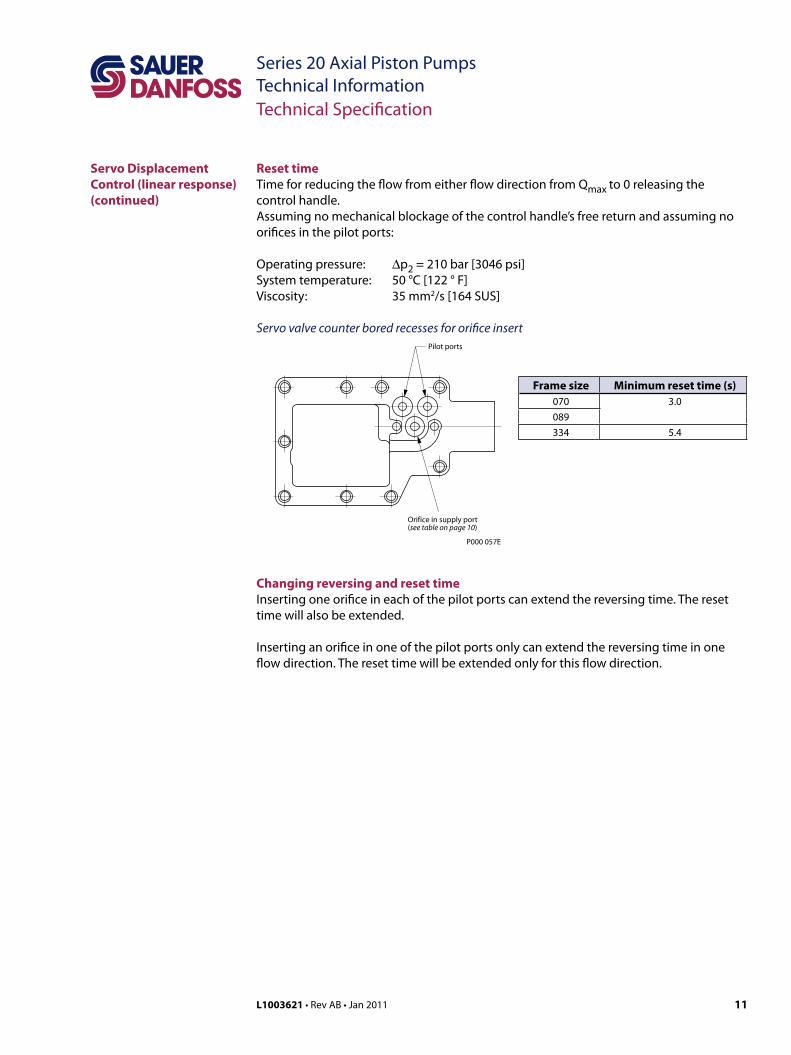
Reset timeTime for reducing the flow from either flow direction from Qmax to 0 releasing the control handle.Assuming no mechanical blockage of the control handle’s free return and assuming no orifices in the pilot ports:
Operating pressure: ∆p2 = 210 bar [3046 psi]System temperature: 50 °C [122 ° F]Viscosity: 35 mm2/s [164 SUS]
Servo Displacement Control (linear response)(continued)
Technical Specification
Pilot ports
Orifice in supply port(see table on page 10)
P000 057E
Servo valve counter bored recesses for orifice insert
Frame size Minimum reset time (s)070 3.0089334 5.4
Changing reversing and reset timeInserting one orifice in each of the pilot ports can extend the reversing time. The reset time will also be extended.
Inserting an orifice in one of the pilot ports only can extend the reversing time in one flow direction. The reset time will be extended only for this flow direction.
12 L1003621 • Rev AB • Jan 2011
Series 20 Axial Piston PumpsTechnical InformationDimensions – Frame Size 070 and 089 cm3
27.79
57.1
5
Charge pressurerelief valve
Port "B"
Port
"S"68
.336
.6
Clo
lcw
ise
(R)
rota
tio
n
Co
un
ter-
clo
lcw
ise
(L)
rota
tio
n
Gauge port - servo cylinder pressure(both sides) 7/16-20 UNF-2BSAE straight threadO-ring boss
56
B
J
K
L
M
Port "L1": Case drain port(use highest port as outlet)
Coupling may not protrudebeyond 48 mm maximumlenght of full spline
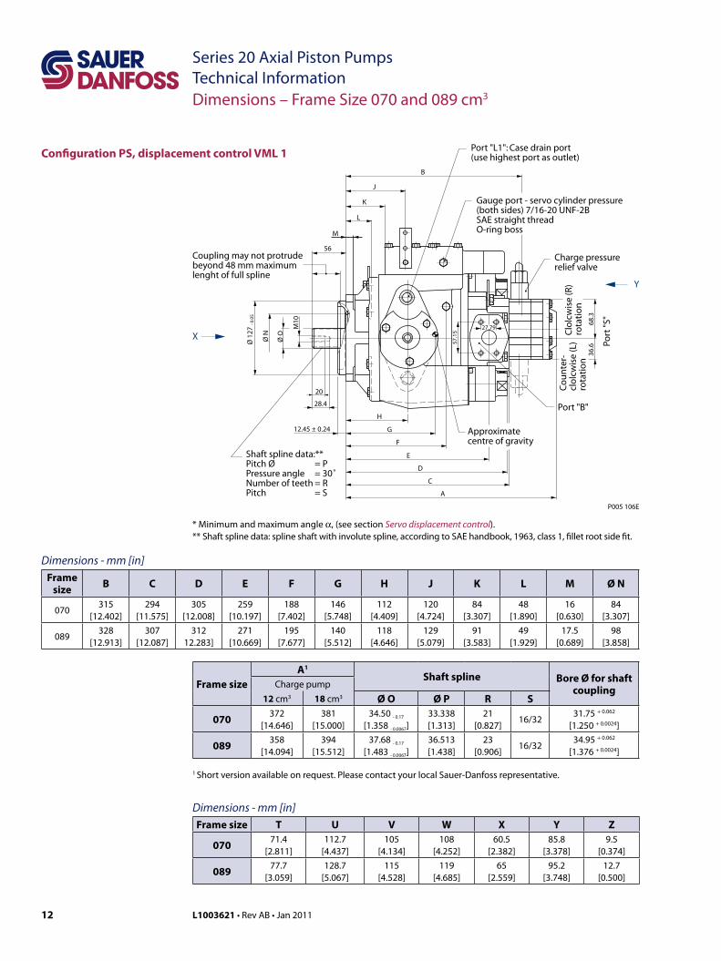
Shaft spline data:**Pitch Ø = PPressure angle = 30˚Number of teeth = RPitch = S
12.45 ± 0.24
28.4
20
H
G
F
E
D
C
A
Approximatecentre of gravity
Ø 1
27 -
0.05
Ø N
Ø O
M10
X
Y
P005 106E
Configuration PS, displacement control VML 1
* Minimum and maximum angle α, (see section Servo displacement control).** Shaft spline data: spline shaft with involute spline, according to SAE handbook, 1963, class 1, fillet root side fit.
Dimensions - mm [in]Frame
size B C D E F G H J K L M Ø N
070315
[12.402]294
[11.575]305
[12.008]259
[10.197]188
[7.402]146
[5.748]112
[4.409]120
[4.724]84
[3.307]48
[1.890]16
[0.630]84
[3.307]
089328
[12.913]307
[12.087]312
12.283]271
[10.669]195
[7.677]140
[5.512]118
[4.646]129
[5.079]91
[3.583]49
[1.929]17.5
[0.689]98
[3.858]
Dimensions - mm [in]Frame size T U V W X Y Z
070 71.4[2.811]
112.7[4.437]
105[4.134]
108[4.252]
60.5[2.382]
85.8[3.378]
9.5[0.374]
089 77.7[3.059]
128.7[5.067]
115[4.528]
119[4.685]
65[2.559]
95.2[3.748]
12.7[0.500]
Frame sizeA1
Shaft spline Bore Ø for shaft couplingCharge pump
12 cm3 18 cm3 Ø O Ø P R S
070 372[14.646]
381[15.000]
34.50 - 0.17
[1.358 - 0.0067]33.338[1.313]
21[0.827]
16/3231.75 + 0.062
[1.250 + 0.0024]
089 358[14.094]
394[15.512]
37.68 - 0.17
[1.483 - 0.0067]36.513[1.438]
23[0.906]
16/3234.95 + 0.062
[1.376 + 0.0024]
1 Short version available on request. Please contact your local Sauer-Danfoss representative.
13L1003621 • Rev AB • Jan 2011
Series 20 Axial Piston PumpsTechnical Information
Null position
Maximumdisplacement
Maximumdisplacement
Serrated shaft
Control handle
C D
α α* *
19 - 0.2+0.3
R 25.4
6.73
± 0
.1
R 50.8
View Z
P000 022E
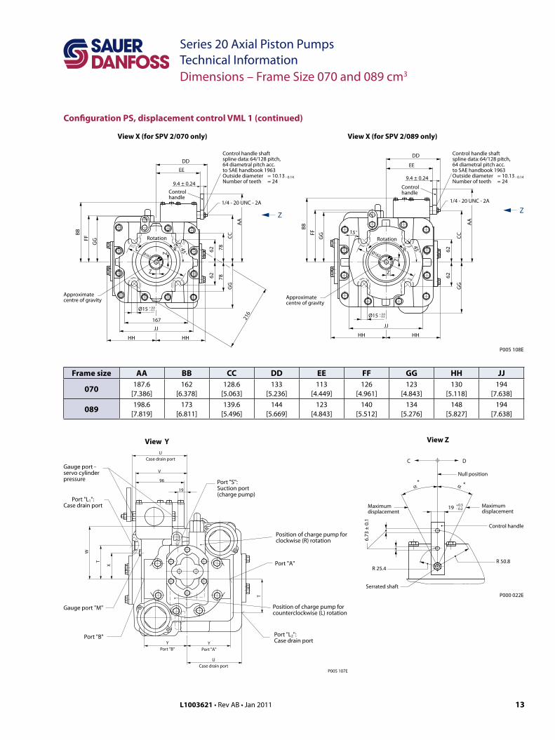
Dimensions – Frame Size 070 and 089 cm3
Configuration PS, displacement control VML 1 (continued)
CC
6262
GG
AA
Ø162
JJ
Ø15 + 0.8– 0.3
Rotation
L R
45˚
Approximatecentre of gravity
View X (for SPV 2/089 only)
HH HH
Z
Z
BB
FF
GG
DD
EE
9.4 ± 0.24
Controlhandle
1/4 - 20 UNC - 2A
Control handle shaftspline data: 64/128 pitch,64 diametral pitch acc.to SAE handbook 1963Outside diameter = 10.13 - 0.14Number of teeth = 24
Z
P005 108E
15˚C
C
6262
GG
AA
Ø162
JJ
Ø15 + 0.8– 0.3
Rotation
L R 45˚
Approximatecentre of gravity
View X (for SPV 2/070 only)
HH HH
Z
Z
BB
FF
GG
DD
EE
9.4 ± 0.24
Controlhandle
1/4 - 20 UNC - 2A
Control handle shaftspline data: 64/128 pitch,64 diametral pitch acc.to SAE handbook 1963Outside diameter = 10.13 - 0.14Number of teeth = 24
Z78
78
167 216
Frame size AA BB CC DD EE FF GG HH JJ
070 187.6[7.386]
162[6.378]
128.6[5.063]
133[5.236]
113[4.449]
126[4.961]
123[4.843]
130[5.118]
194[7.638]
089 198.6[7.819]
173[6.811]
139.6[5.496]
144[5.669]
123[4.843]
140[5.512]
134[5.276]
148[5.827]
194[7.638]
View Y
V
96
19
YPort "B"
YPort "A"
UCase drain port
W
T
X
UCase drain port
Port "S":Suction port(charge pump)
Position of charge pump forclockwise (R) rotation
Position of charge pump forcounterclockwise (L) rotation
Port "A"
T
Port "L2":Case drain port
Port "B"
Gauge port "M"
Port "L1":Case drain port
Gauge port -servo cylinderpressure
P005 107E
14 L1003621 • Rev AB • Jan 2011
Series 20 Axial Piston PumpsTechnical InformationDimensions – Frame Size 070 and 089 cm3
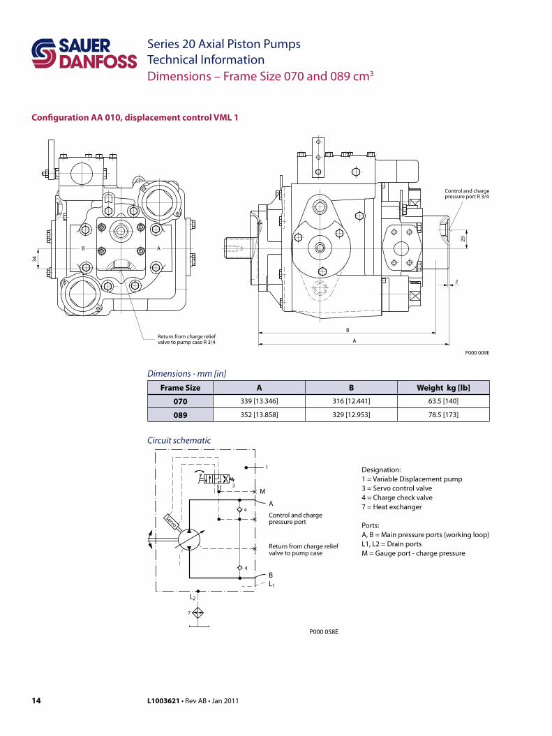
Designation:1 = Variable Displacement pump3 = Servo control valve4 = Charge check valve7 = Heat exchanger
Ports:A, B = Main pressure ports (working loop)L1, L2 = Drain portsM = Gauge port - charge pressure
3
Servo
4
4
M
A
BL1
L2
1
7
Control and chargepressure port
Return from charge reliefvalve to pump case
P000 058E
Configuration AA 010, displacement control VML 1
P000 009E
B
A
2
29
34
Return from charge reliefvalve to pump case R 3/4
Control and chargepressure port R 3/4
AB
Dimensions - mm [in]Frame Size A B Weight kg [lb]
070 339 [13.346] 316 [12.441] 63.5 [140]
089 352 [13.858] 329 [12.953] 78.5 [173]
Circuit schematic
15L1003621 • Rev AB • Jan 2011
Series 20 Axial Piston PumpsTechnical InformationDimensions – Frame Size 334 cm3
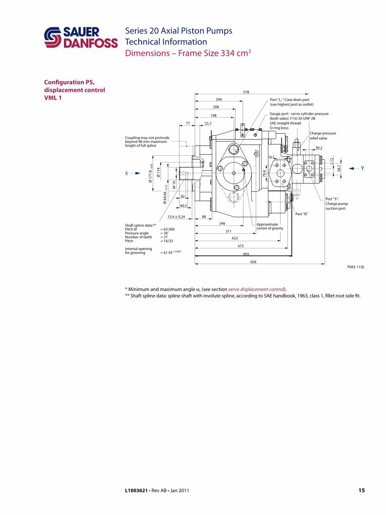
36.5
79.4
Charge pressurerelief valve
Port "B"
Port "S":Charge pumpsuction port
77
Port "L1": Case drain port(use highest port as outlet)
Coupling may not protrudebeyond 48 mm maximumlenght of full spline
Shaft spline data:**Pitch Ø = 63.500Pressure angle = 30˚Number of teeth = 27Pitch = 16/32
Internal openingfor grooving = 61.93 + 0.062
15.6 ± 0.24
40.5
656
Approximatecentre of gravity
Ø 1
77.8
- 0.
05
Ø 1
14
Ø 6
4.66
- 0.
16 M 1
6X
Y
2.12
Gauge port - servo cylinder pressure(both sides) 7/16-20 UNF-2BSAE straight threadO-ring boss
246
433
475
25.5
208
244
578
198
86
311
493
P005 115E
30.2
58.7
30
Configuration PS, displacement control VML 1
* Minimum and maximum angle α, (see section servo displacement control).** Shaft spline data: spline shaft with involute spline, according to SAE handbook, 1963, class 1, fillet root side fit.
16 L1003621 • Rev AB • Jan 2011
Series 20 Axial Piston PumpsTechnical Information
Null position
Maximumdisplacement
Maximumdisplacement
Serrated shaft
Control handle
C D
26.7˚min.* *
19 - 0.2+0.3
R 25.4
6.73
± 0
.1
R 50.8
View Z
26.7˚min.
P000 026E
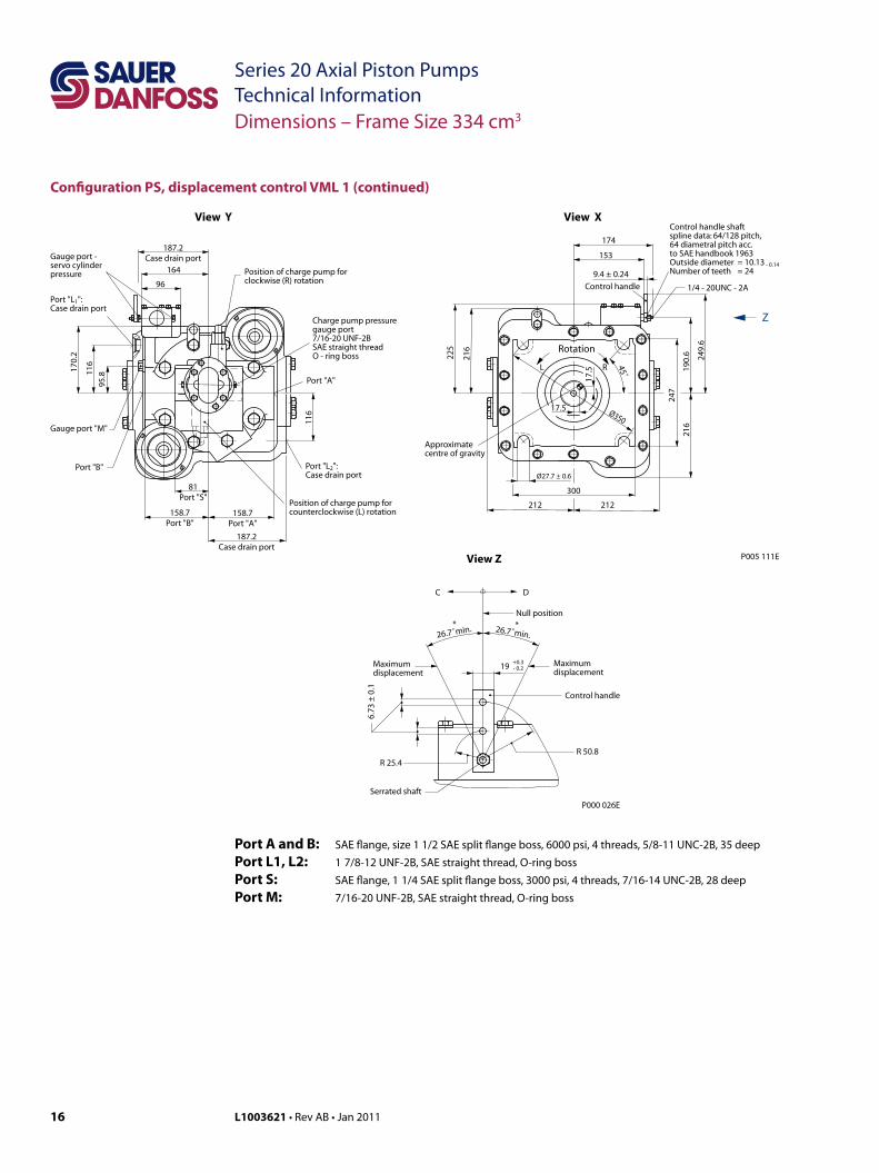
Configuration PS, displacement control VML 1 (continued)
Position of charge pump forclockwise (R) rotation
Position of charge pump forcounterclockwise (L) rotation
Port "A"
Port "L2":Case drain port
Port "B"
Gauge port "M"
Gauge port -servo cylinderpressure
Charge pump pressuregauge port7/16-20 UNF-2BSAE straight threadO - ring boss
Port "L1":Case drain port
164
96
158.7Port "B"
158.7Port "A"
187.2Case drain port
187.2Case drain port
81Port "S"
170.
2
116
95.8
116
View Y
Ø35017.5
17.5
Z
Rotation
Control handle 1/4 - 20UNC - 2A
Control handle shaftspline data: 64/128 pitch,64 diametral pitch acc.to SAE handbook 1963Outside diameter = 10.13 - 0.14Number of teeth = 24
Approximatecentre of gravity
300
Ø27.7 ± 0.6
View X
174
153
9.4 ± 0.24
212 212
216
247
190.
621
6
249.
6
45˚
L R
225
P005 111E
Dimensions – Frame Size 334 cm3
Port A and B: SAE flange, size 1 1/2 SAE split flange boss, 6000 psi, 4 threads, 5/8-11 UNC-2B, 35 deepPort L1, L2: 1 7/8-12 UNF-2B, SAE straight thread, O-ring bossPort S: SAE flange, 1 1/4 SAE split flange boss, 3000 psi, 4 threads, 7/16-14 UNC-2B, 28 deepPort M: 7/16-20 UNF-2B, SAE straight thread, O-ring boss
17L1003621 • Rev AB • Jan 2011
Series 20 Axial Piston PumpsTechnical Information
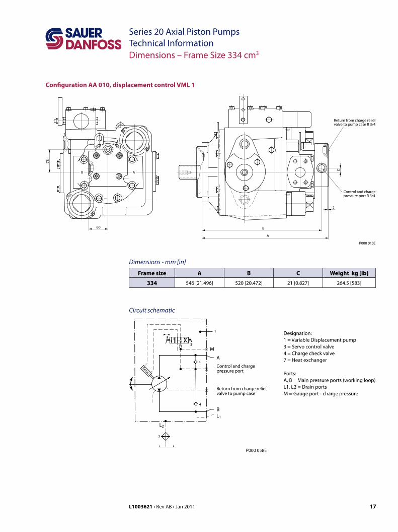
Configuration AA 010, displacement control VML 1
Dimensions – Frame Size 334 cm3
P000 010E
B
A
2
C
73
Control and chargepressure port R 3/4
AB
Return from charge reliefvalve to pump case R 3/4
60
Dimensions - mm [in]
Frame size A B C Weight kg [lb]
334 546 [21.496] 520 [20.472] 21 [0.827] 264.5 [583]
Designation:1 = Variable Displacement pump3 = Servo control valve4 = Charge check valve7 = Heat exchanger
Ports:A, B = Main pressure ports (working loop)L1, L2 = Drain portsM = Gauge port - charge pressure
3
Servo
4
4
M
A
BL1
L2
1
7
Control and chargepressure port
Return from charge reliefvalve to pump case
P000 058E
Circuit schematic
Local address:
Sauer-Danfoss GmbH & Co. OHGPostfach 2460, D-24531 NeumünsterKrokamp 35, D-24539 Neumünster, GermanyPhone: +49 4321 871 0Fax: +49 4321 871 122
Sauer-Danfoss ApSDK-6430 Nordborg, DenmarkPhone: +45 7488 4444Fax: +45 7488 4400
Sauer-Danfoss is a global manufacturer and supplier of high-quality hydraulic and electronic components. We specialize in providing state-of-the-art technology and solutions that excel in the harsh operating conditions of the mobile off -highway market. Building on our extensive applications expertise, we work closely with our customers to ensure exceptional performance for a broad range of off -highway vehicles.
We help OEMs around the world speed up system development, reduce costs and bring vehicles to market faster. Sauer-Danfoss – Your Strongest Partner in Mobile Hydraulics.
Go to www.sauer-danfoss.com for further product information.
Wherever off -highway vehicles are at work, so is Sauer-Danfoss.
We off er expert worldwide support for our customers, ensuring the best possible solutions for outstanding performance. And with an extensive network of Global Service Partners, we also provide comprehensive global service for all of our components.
Please contact the Sauer-Danfoss representative nearest you.
Products we off er:
• Bent Axis Motors
• Closed Circuit Axial Piston Pumps and Motors
• Displays
• Electrohydraulic Power Steering
• Electrohydraulics
• Hydraulic Power Steering
• Integrated Systems
• Joysticks and Control Handles
• Microcontrollers and Software
• Open Circuit Axial Piston Pumps
• Orbital Motors
• PLUS+1™ GUIDE
• Proportional Valves
• Sensors
• Steering
• Transit Mixer Drives
Members of the Sauer-Danfoss Group:
Comatrolwww.comatrol.com
Schwarzmüller-Inverterwww.schwarzmueller-inverter.com
Turolla www.turollaocg.com
Hydro-Gear www.hydro-gear.com
Sauer-Danfoss-Daikinwww.sauer-danfoss-daikin.com
Sauer-Danfoss (US) Company2800 East 13th StreetAmes, IA 50010, USAPhone: +1 515 239 6000Fax: +1 515 239 6618
Sauer-Danfoss-Daikin LTD.Shin-Osaka TERASAKI 3rd Bldg. 6F1-5-28 Nishimiyahara, Yodogawa-kuOsaka 532-0004, JapanPhone: +81 6 6395 6066Fax: +81 6 6395 8585
w w w . s a u e r - d a n f o s s . c o mL1003621 • Rev AB • Jan 2011


