series 3500 BOOM TRUCKS • 35 Ton (31,8 mton) Capacity • 5-Section 124' (37,8 m) Proportional Boom • 4-Section 100' (30,5 m) Proportional Boom • 3-Section 77' (23,5 m) Proportional Boom • 1 and 2-Section 30' 6" (9,3 m) to 55' (16,8 m) Jib • 165' 11" (50,6 m) Maximum Tip Height • 22', 1.25" (6,7 m) Out-and-Down Outriggers at Full Extension • Intermediate and Fully Extended Outrigger Charts are Standard • FirstUp for Optional Front Stabilizer Auto Retract • 2-Speed Planetary Hoist with Grooved Drum and Negative Draft Flange • Load Moment Indicator with Digital Display, CAN Bus, Overload Shutdown and Internal Boom Length Cable • Radio ATB • Rugged, Weatherproof Electrical System with Circuit Status LEDs • Removable Boom Rest • System Pressure Gauge • Clamp-On Mounting • Manitex UPTime Comprehensive Support product guide features
Transcript
series 3500B O O M T R U C K S
• 35 Ton (31,8 mton) Capacity
• 5-Section 124' (37,8 m)Proportional Boom
• 4-Section 100' (30,5 m)Proportional Boom
• 3-Section 77' (23,5 m)Proportional Boom
• 1 and 2-Section 30' 6" (9,3 m)to 55' (16,8 m) Jib
• 165' 11" (50,6 m) MaximumTip Height
• 22', 1.25" (6,7 m) Out-and-DownOutriggers at Full Extension
• Intermediate and Fully ExtendedOutrigger Charts are Standard
• FirstUp for Optional Front StabilizerAuto Retract
• 2-Speed Planetary Hoist with GroovedDrum and Negative Draft Flange
• Load Moment Indicator with DigitalDisplay, CAN Bus, Overload Shutdownand Internal Boom Length Cable
• Radio ATB
• Rugged, Weatherproof ElectricalSystem with Circuit Status LEDs
• Removable Boom Rest
• System Pressure Gauge
• Clamp-On Mounting
• Manitex UPTimeComprehensive Support
product guide
features
Manitex3000 South Austin AvenueGeorgetown, TX, USA 78626Telephone 512-942-3000Facsimile 512-863-3776www.manitex.com
• Includes 24-7-365 parts shipments.
• Utilizes the efficiency of UPNet online partsorder system.
• Relies on Manitex’s UPTrak support tracking systemfor performance analysis and resource allocation.
• Features REMan, Manitex’s cost effectiverebuild/exchange program.
• Provides expert service technicians for troubleshootingand site visits.
• Mandates training; at our facility and yours. It includescoordinated support from all component suppliers.
• Involves every Manitex team member in the supportof every Manitex customer.
What does UPTime mean to Manitex cus-tomers?
UPTime means reliability.
UPTime means utilization.
UPTime means profitability.
UPTime is the Manitex commitmentto complete support of thousands ofunits working every day.
DEDUCTIONS
Auxiliary Block 50 lb22.72 kg
Load Block See blockmanufacturer nameplate
Overhaul Ball See overhaul ballmanufacturer nameplate
Hose Reel 260 lb118.18 kg
Swing Around Jib* (Stowed) See load rating chart
AREA OF OPERATION
WEIGHTS
1 Part Line 2 Part Line 3 Part Line 4 Part Line 5 Part Line 6 Part Line 7 Part Line 8 Part Line WARNING
OVER
HAUL
BALL
SING
LESH
EAVE
BLOC
K
SING
LESH
EAVE
BLOC
K
3OR
4SH
EAVE
BLOC
K
3OR
4SH
EAVE
BLOC
K
3OR
4SH
EAVE
BLOC
K
3OR
4SH
EAVE
BLOC
KAU
XILI
ARY
BLOC
K
AUXI
LIAR
YBL
OCK
4SH
EAVE
BLOC
K
Anti-two-block systemmust be in goodoperating conditionbefore operating crane.Refer to the owner’smanual. Keep at leastthree wraps of loadline on the drum atall times.
42560_3500.qxd:3500_MTXBroch(FINAL).qxd 11/15/07 8:52 AM Page 1
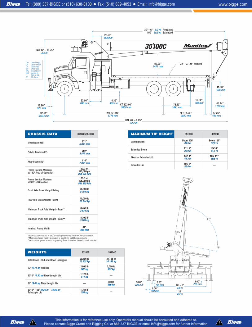
OAH 12' – 10.75"3,9 m
12.90"323 mm
32.61"815.4 mm
26.50"663 mm
30' – 6" 9,3 m Retracted100' 30,5 m Extended
59.09"1477 mm
22' – 3.125" Flatbed
41.00"1025 mm
45.44"1136 mm
17.25"431 mm
73.63"1841 mm
12.02"300 mm
AF 114.00"2850 mm
14.35"359 mm CT 202.00"
5050 mm
WB 271.00"6775 mm
OAL 40' – 0.25"12,2 m
32.00"800 mm
CHASSIS DATA 35100C/35124C
Wheelbase (WB) 271"6 883 mm
Cab to Tandem (CT) 202"4 877 mm
After Frame (AF) 114"2 896 mm
Frame Section Modulusat 180º Area of Operation
30.0 in3125,000 psi861 875 kPa
Frame Section Modulusat 360º of Operation
30.0 in3125,000 psi861 875 kPa
Front Axle Gross Weight Rating 20,000 lb8 165 kg
Rear Axle Gross Weight Rating 40,000 lb18 144 kg
Minimum Truck Axle Weight - Front** 8,450 lb3 674 kg
Minimum Truck Axle Weight - Back** 8,300 lb3 765 kg
Nominal Frame Width 34"864 mm
*Frame section modulus at 360˚ area of operation requires front bumper stabilizer.**Minimum chassis weight is required to meet 85% stability requirements.Chassis data is general – not for engineering. Some dimensions depend on truck selection.
WEIGHTS 35100C 35124C
Total Crane - Out-and-Down Outriggers 29,706 lb13 502 kg
31,126 lb14 148 kg
22' (6,71 m) Flat Bed 2,000 lb907 kg
2,000 lb907 kg
30' 6" (9,30 m) Fixed Length Jib 1,126 lb511 kg —
31' (9,45 m) Fixed Length Jib — 850 lb386 kg
30' 6" – 55' (9,30 m – 16,80 m)Telescopic Jib
1,754 lb796 kg —
MAXIMUM TIP HEIGHT 35100C 35124C
Configuration Boom 100'30,5 m
Boom 124'37,8 m
Extended Boom 111' 4"33,9 m
134' 8"41,1 m
Fixed or Retracted Jib 142' 1"43,3 m
165' 11"50,6 m
Extended Jib 166' 8"50,8 m —
9.00"223 mm
6.00"150 mm
8.00"200 mm
18' – 6"5,6 m
22'6,7 m
9.00"228 mm
10º
81º
OAH Overall HeightCT Cab to TandemCA Cab to AxleWB Wheel BaseOAL Overall LengthBBC Bumper to
Back of CabAF Afterframe
BOOM
Booms – Inverted T-cross section, 3,4, or 5-sectiontelescoping type, extended and retracted propor-tionally by a double-acting hydraulic cylinder andcable-crowd system. 35100 – 4-Section 30' 6"(9,3 m) to 100' 0" (30,5 m). 2-section, 31' (9,5 m)to 55' (16,8 m) jib. 35124C – 5-section 31' 5/8"(9,5 m) to 123' 8 5/8" (37,7 m). 1-section, 31'(9,5 m) jib. 3577C – 3-section, 29' 5" (9 m) to77' (23,5 m).
Quick Reeve Boom Point – Three high-densitynylon load sheaves mounted on heavy-duty rollerbearings. Two removable pin-type rope guards.
Boom Elevation – Double-acting hydrauliccylinder. Working range from 10˚ below horizontalto 80˚ above.
Load Hook – 5-ton (4,5 mton) capacity hookwith heavy-duty swivel and weight is provided forsingle-line operation.
HOIST
Hoist – Maximum theoretical line speed 453 fpm(138 mpm). Maximum theoretical bottom-layer linepull 14,500 lb (6 577 kg). Two-speed planetaryreducer. Wet multi-disc internal brake is spring-applied, pressure-released.
Wire Rope – 380' (115,8 m) of 5/8" (16 mm)rotation resistant type.
SWING SYSTEM
Externally mounted, double-reduction planetarydriven by hydraulic motor. Maximum theoreticalswing speed 1.5 rpm. Wet multi-disk internalbrake is spring-applied, pressure-released.Oversized diameter ball-bearing swing circle withexternal gear. 372˚ non-continuous rotation.
OUTRIGGERS
Out-and-down style outriggers, operated inde-pendently for precise leveling. 22' 1 1/4" (6,8 m)spread at full extension and 13' 4" (4,1 m) spreadat intermediate extension. 16" (406 mm) diameterfloats. Bubble level located near outrigger controls.
STABILIZERS
8' (2,4 m) retracted; 18' 6" (5,6 m) extended.Operated independently for precise leveling.Double-acting hydraulic cylinders. Fixed pad sizeis 12" (305 mm) diameter.
Front Bumper stabilizer (option) – Singlestabilizer mounted at the front of the truck forlifting operation over the front (360° area ofoperation). Maximum float load is controlled bypreset counterbalance valve to prevent overloadingthe stabilizer. Stabilizer cylinder protected byauto-retract feature to prevent drive away damage.This option may require front frame extensions-consult factory.
MOUNTING
Mounting – Pedestal and subframe are mountedto chassis by threaded rods and clamp plates.No welding, drilling, or bolting to truck frame isrequired.
Subframe – Torsionally resistant, rigid 4-platedesign. Mounted under crane full length of truckframe.
Rear Underride Protection – Supplied on factory-mounted cranes. Fabricated structure mountedunder rear of bed. Complies with Bureau MotorCarrier Safety Standard 393.86.
Boom Rest – Heavy-duty fabrication. Easilyremoved to simplify loading and unloadingtruck deck.
CONTROL SYSTEM
Dual operator platforms are equipped with foursingle-lever crane controls arranged to ANSI B30.5standards. Fully proportional control valves andsystem pressure gauge. Each station also includesoutrigger and stabilizer controls, engine start/stop,foot throttle, signal horn, boom-angle indicator,bubble levels, beverage container, load chart andrange diagram.
HYDRAULICS
Hydraulic System – A 3-section vane pumpdirect-mounted to power take-off on trucktransmission provides 38 gpm (145 lpm) to the
hoist, 27 gpm (102 lpm) to the boom hoist andtelescope circuit, and 11 gpm (45 lpm) to theswing and outrigger circuit. 100-gallon (379-liter)baffled reservoir includes suction ball valve withstrainer two 25-micron filters in the return line.Use of SAE O-ring and face seal O-ring hydraulicfittings throughout system.Hydraulic Cylinders – All load-holding cylindersare equipped with integral holding valves.
WARNING SYSTEMS
Load Moment Indicator – CAN bus system maxi-mizes expansion capabilities. Senses boom hoistcylinder pressure, boom length and boom angle.Audio-visual warning indicated overload conditionsand overload shutoff feature prevents continuingoverload. Operator can access all relative craneconfiguration and load conditions via display at theoperator station. Internal boom length cable.
Radio Anti-Two-Block System – Audible warningand shutoff functions prevent hook from contactingboom point. Switch is potted to ensure reliability.
Back-Up Alarm – Supplied on factory-mountedcranes, electronic audible motion alarm activatedwhen truck transmission is in reverse gear.
GENERAL
Electrical – State-of-the-art, weather-resistantcomponents throughout. Hermetically sealedpower in relays. Enclosure includes power in relaysand circuit status LEDs. Designed to withstandhigh pressure washing and varying climates.
Design/Welding – Design conforms to ANSIB30.5. Welding conforms to AWS D1.1. Tested toSAE 1063 and SAE 765.
Manuals – Operator, service and parts manualsdepict correct crane operation, maintenanceprocedures and parts listing.
Warranty – 12-month warranty covers partsand labor resulting from defects in materialand workmanship.
* In order to ensure continuous improvement,specifications may change without notice.
series 3500G E N E R A L S P E C I F I C A T I O N S
USE THIS CHART ONLY WHENOUTRIGGERS AND STABILIZERS ARE
FULLY EXTENDED.
FULLY EXTENDED OUTRIGGER SPREAD: MODEL 35100C
MAIN BOOM LOAD RATINGS JIB LOAD RATINGS
Boom Length A B C D Fixed Jib Telescopic Jib
Operating Radius 30.5 Feet9,30 Meters
52 Feet15,85 Meters
68 Feet20,73 Meters
84 Feet25,60 Meters
100 Feet30,48 Meters
30.5 Feet9,30 Meters
30.5 Feet9,30 Meters
55 Feet16,76 Meters
Feet Meters lb. kg. lb. kg. lb. kg. lb. kg. lb. kg. lb. kg. lb. kg. lb. kg.
Pins must bedisengaged forthis outriggerconfiguration.
These marksindicate whenbeams are
fully extended.
All outriggerbeams must beextended to fullextend mark.
First Section
Ground
Outriggers Stabilizers
222.00 REF (18' – 6")
264.00 REF (22' – 0")
SecondSection
Meets ANSI B30.5 Requirements - Do not operate crane or accessories within 10' (3,05m) of live power lines.NOTICE: This chart is for reference only and must not be used for lifting purposes. Consult factory for other boom options.
42560_3500.qxd:3500_MTXBroch(FINAL).qxd 11/15/07 8:52 AM Page 4
series 3500B O O M T R U C K S
• 35 Ton (31,8 mton) Capacity
• 5-Section 124' (37,8 m)Proportional Boom
• 4-Section 100' (30,5 m)Proportional Boom
• 3-Section 77' (23,5 m)Proportional Boom
• 1 and 2-Section 30' 6" (9,3 m)to 55' (16,8 m) Jib
• 165' 11" (50,6 m) MaximumTip Height
• 22', 1.25" (6,7 m) Out-and-DownOutriggers at Full Extension
• Intermediate and Fully ExtendedOutrigger Charts are Standard
• FirstUp for Optional Front StabilizerAuto Retract
• 2-Speed Planetary Hoist with GroovedDrum and Negative Draft Flange
• Load Moment Indicator with DigitalDisplay, CAN Bus, Overload Shutdownand Internal Boom Length Cable
• Radio ATB
• Rugged, Weatherproof ElectricalSystem with Circuit Status LEDs
• Removable Boom Rest
• System Pressure Gauge
• Clamp-On Mounting
• Manitex UPTimeComprehensive Support
product guide
features
Manitex3000 South Austin AvenueGeorgetown, TX, USA 78626Telephone 512-942-3000Facsimile 512-863-3776www.manitex.com
• Includes 24-7-365 parts shipments.
• Utilizes the efficiency of UPNet online partsorder system.
• Relies on Manitex’s UPTrak support tracking systemfor performance analysis and resource allocation.
• Features REMan, Manitex’s cost effectiverebuild/exchange program.
• Provides expert service technicians for troubleshootingand site visits.
• Mandates training; at our facility and yours. It includescoordinated support from all component suppliers.
• Involves every Manitex team member in the supportof every Manitex customer.
What does UPTime mean to Manitex cus-tomers?
UPTime means reliability.
UPTime means utilization.
UPTime means profitability.
UPTime is the Manitex commitmentto complete support of thousands ofunits working every day.
DEDUCTIONS
Auxiliary Block 50 lb22.72 kg
Load Block See blockmanufacturer nameplate
Overhaul Ball See overhaul ballmanufacturer nameplate
Hose Reel 260 lb118.18 kg
Swing Around Jib* (Stowed) See load rating chart
AREA OF OPERATION
WEIGHTS
1 Part Line 2 Part Line 3 Part Line 4 Part Line 5 Part Line 6 Part Line 7 Part Line 8 Part Line WARNING
OVER
HAUL
BALL
SING
LESH
EAVE
BLOC
K
SING
LESH
EAVE
BLOC
K
3OR
4SH
EAVE
BLOC
K
3OR
4SH
EAVE
BLOC
K
3OR
4SH
EAVE
BLOC
K
3OR
4SH
EAVE
BLOC
KAU
XILI
ARY
BLOC
K
AUXI
LIAR
YBL
OCK
4SH
EAVE
BLOC
K
Anti-two-block systemmust be in goodoperating conditionbefore operating crane.Refer to the owner’smanual. Keep at leastthree wraps of loadline on the drum atall times.
42560_3500.qxd:3500_MTXBroch(FINAL).qxd 11/15/07 8:52 AM Page 1
series 3500B O O M T R U C K S
• 35 Ton (31,8 mton) Capacity
• 5-Section 124' (37,8 m)Proportional Boom
• 4-Section 100' (30,5 m)Proportional Boom
• 3-Section 77' (23,5 m)Proportional Boom
• 1 and 2-Section 30' 6" (9,3 m)to 55' (16,8 m) Jib
• 165' 11" (50,6 m) MaximumTip Height
• 22', 1.25" (6,7 m) Out-and-DownOutriggers at Full Extension
• Intermediate and Fully ExtendedOutrigger Charts are Standard
• FirstUp for Optional Front StabilizerAuto Retract
• 2-Speed Planetary Hoist with GroovedDrum and Negative Draft Flange
• Load Moment Indicator with DigitalDisplay, CAN Bus, Overload Shutdownand Internal Boom Length Cable
• Radio ATB
• Rugged, Weatherproof ElectricalSystem with Circuit Status LEDs
• Removable Boom Rest
• System Pressure Gauge
• Clamp-On Mounting
• Manitex UPTimeComprehensive Support
product guide
features
Manitex3000 South Austin AvenueGeorgetown, TX, USA 78626Telephone 512-942-3000Facsimile 512-863-3776www.manitex.com
• Includes 24-7-365 parts shipments.
• Utilizes the efficiency of UPNet online partsorder system.
• Relies on Manitex’s UPTrak support tracking systemfor performance analysis and resource allocation.
• Features REMan, Manitex’s cost effectiverebuild/exchange program.
• Provides expert service technicians for troubleshootingand site visits.
• Mandates training; at our facility and yours. It includescoordinated support from all component suppliers.
• Involves every Manitex team member in the supportof every Manitex customer.
What does UPTime mean to Manitex cus-tomers?
UPTime means reliability.
UPTime means utilization.
UPTime means profitability.
UPTime is the Manitex commitmentto complete support of thousands ofunits working every day.
DEDUCTIONS
Auxiliary Block 50 lb22.72 kg
Load Block See blockmanufacturer nameplate
Overhaul Ball See overhaul ballmanufacturer nameplate
Hose Reel 260 lb118.18 kg
Swing Around Jib* (Stowed) See load rating chart
AREA OF OPERATION
WEIGHTS
1 Part Line 2 Part Line 3 Part Line 4 Part Line 5 Part Line 6 Part Line 7 Part Line 8 Part Line WARNING
OVER
HAUL
BALL
SING
LESH
EAVE
BLOC
K
SING
LESH
EAVE
BLOC
K
3OR
4SH
EAVE
BLOC
K
3OR
4SH
EAVE
BLOC
K
3OR
4SH
EAVE
BLOC
K
3OR
4SH
EAVE
BLOC
KAU
XILI
ARY
BLOC
K
AUXI
LIAR
YBL
OCK
4SH
EAVE
BLOC
K
Anti-two-block systemmust be in goodoperating conditionbefore operating crane.Refer to the owner’smanual. Keep at leastthree wraps of loadline on the drum atall times.