105
Series 50 T (M1310A) Fetal Telemetry System SERVICE GUIDE M1310-9000B Printed in Germany February 2002 Edition 1, A.00.01

Series 50 T (M1310A)Fetal Telemetry System
S E R V I C E G U I D EM1310-9000B
Printed in Germany February 2002
Edition 1, A.00.01

Notice
Philips makes no warranty of any kind with regard to this material, including, but not limited to, the implied warranties of merchantability and fitness for a particular purpose. Philips shall not be liable for errors contained herein or for incidental or consequential damages in connection with the furnishing, performance or use of this material.
The information contained in this document is subject to change without notice.
Philips assumes no responsibility for the use or reliability of its software on equipment that is not furnished by Philips.
Responsibility of the Manufacturer
Philips only considers itself responsible for any effects on safety, reliability and performance of the equipment if:
• assembly operations, extensions, re-adjustments, modifications or repairs are carried out by persons authorized by Philips, and
• the electrical installation of the relevant room complies with national standards, and
• the instrument is used in accordance with the Instructions for Use or User’s Guide.
Important
United States federal law restricts this device to sale by or on the order of a physician.
This device is not intended for home use.
WarningFailure on the part of the responsible individual hospital or institution employing the use of this equipment to implement a satisfactory maintenance schedule may cause undue equipment failure and possible health hazards.

Printing History
M1310-9000A April 1994M1310-9000B February 2002
About this Manual
The manual is intended for personnel involved in the service and repair of the M1310 Telemetry System.It enables you to diagnose and repair problems with the minimum of inconvenience to the customer.
The philosophy for on-site diagnosis and repair of the M1310A Telemetry System can be summarized as follows:
• General Repair Strategy
• On-site repair for standard assemblies.
• Bench repair for RF-repair.
The recommended repair method is replacement of assemblies.
Every 12 months, you must carry out a series of preventive maintenance tasks and performance assurance tests. Details can be found in Chapter 10, “Preventive Maintenance, Care and Cleaning”.
For an overview of the system, and how to set it up, please refer to the Instructions for Use.
Conventional current technical terms are used throughout the manual, and familiarity with these terms is assumed.
The following conventions for cautions and warnings are used in this guide:
Note— A note calls attention to an important point in the text.
WarningA warning calls attention to a condition or possible situation that could cause injury to the user and/or patient.
CautionA caution calls attention to a condition or possible situation that could damage or destroy the product or the user’s work.
2002 Philips Medizinsysteme GmbH
All rights are reserved. Reproduction in whole or in part is prohibited without the prior written consent of the copyright holder.

Contents
1.Safety . . . . . . . . . . . . . . . . . . . . . . . . . . . . . . . . . . . . . . . . . . . . . . . . . . . . . . . . . 1Safety Symbols . . . . . . . . . . . . . . . . . . . . . . . . . . . . . . . . . . . . . . . . . . . . . . . . . . . . . . . . . . . . . . . . . . . . . 1Patient Safety . . . . . . . . . . . . . . . . . . . . . . . . . . . . . . . . . . . . . . . . . . . . . . . . . . . . . . . . . . . . . . . . . . . . . . 2Environment . . . . . . . . . . . . . . . . . . . . . . . . . . . . . . . . . . . . . . . . . . . . . . . . . . . . . . . . . . . . . . . . . . . . . . 2Protective Earth. . . . . . . . . . . . . . . . . . . . . . . . . . . . . . . . . . . . . . . . . . . . . . . . . . . . . . . . . . . . . . . . . . . . 3Maximum Input/Output Voltages . . . . . . . . . . . . . . . . . . . . . . . . . . . . . . . . . . . . . . . . . . . . . . . . . . . . . . 4
2.Technical Specifications . . . . . . . . . . . . . . . . . . . . . . . . . . . . . . . . . . . . . . . . . . 5Telemetry System (Receiver and Transmitter) . . . . . . . . . . . . . . . . . . . . . . . . . . . . . . . . . . . . . . . . . . . 5
Power Requirements . . . . . . . . . . . . . . . . . . . . . . . . . . . . . . . . . . . . . . . . . . . . . . . . . . . . . . . . . . . . 5Environment . . . . . . . . . . . . . . . . . . . . . . . . . . . . . . . . . . . . . . . . . . . . . . . . . . . . . . . . . . . . . . . . . . . 5Dimensions and Weight . . . . . . . . . . . . . . . . . . . . . . . . . . . . . . . . . . . . . . . . . . . . . . . . . . . . . . . . . . 5Controls and Indicators . . . . . . . . . . . . . . . . . . . . . . . . . . . . . . . . . . . . . . . . . . . . . . . . . . . . . . . . . . 6Channels and Frequencies . . . . . . . . . . . . . . . . . . . . . . . . . . . . . . . . . . . . . . . . . . . . . . . . . . . . . . . . 6Antenna. . . . . . . . . . . . . . . . . . . . . . . . . . . . . . . . . . . . . . . . . . . . . . . . . . . . . . . . . . . . . . . . . . . . . . . 6Inputs. . . . . . . . . . . . . . . . . . . . . . . . . . . . . . . . . . . . . . . . . . . . . . . . . . . . . . . . . . . . . . . . . . . . . . . . . 6Outputs . . . . . . . . . . . . . . . . . . . . . . . . . . . . . . . . . . . . . . . . . . . . . . . . . . . . . . . . . . . . . . . . . . . . . . . 7Input Sensitivity . . . . . . . . . . . . . . . . . . . . . . . . . . . . . . . . . . . . . . . . . . . . . . . . . . . . . . . . . . . . . . . . . 7Output Power. . . . . . . . . . . . . . . . . . . . . . . . . . . . . . . . . . . . . . . . . . . . . . . . . . . . . . . . . . . . . . . . . . 7Image Rejection. . . . . . . . . . . . . . . . . . . . . . . . . . . . . . . . . . . . . . . . . . . . . . . . . . . . . . . . . . . . . . . . . 7Self-Test Facilities . . . . . . . . . . . . . . . . . . . . . . . . . . . . . . . . . . . . . . . . . . . . . . . . . . . . . . . . . . . . . . . 7
Transducers and Cables . . . . . . . . . . . . . . . . . . . . . . . . . . . . . . . . . . . . . . . . . . . . . . . . . . . . . . . . . . . . . 8External Blue Toco Transducers (M1355A) or (M1355A Opt. C03) . . . . . . . . . . . . . . . . . . . . . . . 8Blue Ultrasound Transducer (M1356A) or (M1356 Opt. C03) . . . . . . . . . . . . . . . . . . . . . . . . . . . 8DECG Transducer (M1357A) . . . . . . . . . . . . . . . . . . . . . . . . . . . . . . . . . . . . . . . . . . . . . . . . . . . . . 9DECG/MECG Patient Module (M1364A) . . . . . . . . . . . . . . . . . . . . . . . . . . . . . . . . . . . . . . . . . . . . 9
IUP Quartz Transducer (1290C #J05) . . . . . . . . . . . . . . . . . . . . . . . . . . . . . . . . . . . . . . . . . . . . . . . . . . 9IUP Pressure Transducer (CPJ840J5) . . . . . . . . . . . . . . . . . . . . . . . . . . . . . . . . . . . . . . . . . . . . . . . 10Remote Event Marker (15249A) . . . . . . . . . . . . . . . . . . . . . . . . . . . . . . . . . . . . . . . . . . . . . . . . . . 10
3.Tests and Error Messages . . . . . . . . . . . . . . . . . . . . . . . . . . . . . . . . . . . . . . . 11Testing the Receiver . . . . . . . . . . . . . . . . . . . . . . . . . . . . . . . . . . . . . . . . . . . . . . . . . . . . . . . . . . . . . . . 11Testing the Transmitter . . . . . . . . . . . . . . . . . . . . . . . . . . . . . . . . . . . . . . . . . . . . . . . . . . . . . . . . . . . . 12Testing the Parameter Signals . . . . . . . . . . . . . . . . . . . . . . . . . . . . . . . . . . . . . . . . . . . . . . . . . . . . . . . 13Error Messages . . . . . . . . . . . . . . . . . . . . . . . . . . . . . . . . . . . . . . . . . . . . . . . . . . . . . . . . . . . . . . . . . . . 14
Series 50 Family . . . . . . . . . . . . . . . . . . . . . . . . . . . . . . . . . . . . . . . . . . . . . . . . . . . . . . . . . . . . . . . 148040A . . . . . . . . . . . . . . . . . . . . . . . . . . . . . . . . . . . . . . . . . . . . . . . . . . . . . . . . . . . . . . . . . . . . . . . 148041A . . . . . . . . . . . . . . . . . . . . . . . . . . . . . . . . . . . . . . . . . . . . . . . . . . . . . . . . . . . . . . . . . . . . . . . 15
4.Troubleshooting . . . . . . . . . . . . . . . . . . . . . . . . . . . . . . . . . . . . . . . . . . . . . . . 17Solving General Problems . . . . . . . . . . . . . . . . . . . . . . . . . . . . . . . . . . . . . . . . . . . . . . . . . . . . . . . . . . 17
No LEDs Lit on Receiver (continued overleaf) . . . . . . . . . . . . . . . . . . . . . . . . . . . . . . . . . . . . . . 19Not all Receiver LEDs are Lit . . . . . . . . . . . . . . . . . . . . . . . . . . . . . . . . . . . . . . . . . . . . . . . . . . . . 21Yellow LED Remains Lit . . . . . . . . . . . . . . . . . . . . . . . . . . . . . . . . . . . . . . . . . . . . . . . . . . . . . . . . 21Transmission INOP Range . . . . . . . . . . . . . . . . . . . . . . . . . . . . . . . . . . . . . . . . . . . . . . . . . . . . . . 22
Contents v

Transmission Range . . . . . . . . . . . . . . . . . . . . . . . . . . . . . . . . . . . . . . . . . . . . . . . . . . . . . . . . . . . . 23Transducer Mode Not Detected . . . . . . . . . . . . . . . . . . . . . . . . . . . . . . . . . . . . . . . . . . . . . . . . . 24
Cardio Channel . . . . . . . . . . . . . . . . . . . . . . . . . . . . . . . . . . . . . . . . . . . . . . . . . . . . . . . . . . . . . . . . . . 25TOCO Channel . . . . . . . . . . . . . . . . . . . . . . . . . . . . . . . . . . . . . . . . . . . . . . . . . . . . . . . . . . . . . . . . . . 26FMP . . . . . . . . . . . . . . . . . . . . . . . . . . . . . . . . . . . . . . . . . . . . . . . . . . . . . . . . . . . . . . . . . . . . . . . . . . . . 27
FMP Test. . . . . . . . . . . . . . . . . . . . . . . . . . . . . . . . . . . . . . . . . . . . . . . . . . . . . . . . . . . . . . . . . . . . . 27Event Marker . . . . . . . . . . . . . . . . . . . . . . . . . . . . . . . . . . . . . . . . . . . . . . . . . . . . . . . . . . . . . . . . . . . . 29Nurse Call . . . . . . . . . . . . . . . . . . . . . . . . . . . . . . . . . . . . . . . . . . . . . . . . . . . . . . . . . . . . . . . . . . . . . . 30
5.Interfacing to a Fetal Monitor . . . . . . . . . . . . . . . . . . . . . . . . . . . . . . . . . . . . . 31
6.Using the Service Software . . . . . . . . . . . . . . . . . . . . . . . . . . . . . . . . . . . . . . . 33Prerequisites . . . . . . . . . . . . . . . . . . . . . . . . . . . . . . . . . . . . . . . . . . . . . . . . . . . . . . . . . . . . . . . . . . . . . 33Running the Service Software Program . . . . . . . . . . . . . . . . . . . . . . . . . . . . . . . . . . . . . . . . . . . . . . . . 34Using the Service Program . . . . . . . . . . . . . . . . . . . . . . . . . . . . . . . . . . . . . . . . . . . . . . . . . . . . . . . . . . 35
Main Menu . . . . . . . . . . . . . . . . . . . . . . . . . . . . . . . . . . . . . . . . . . . . . . . . . . . . . . . . . . . . . . . . . . . 35
7.Replacing Parts . . . . . . . . . . . . . . . . . . . . . . . . . . . . . . . . . . . . . . . . . . . . . . . . . 39Ordering Parts . . . . . . . . . . . . . . . . . . . . . . . . . . . . . . . . . . . . . . . . . . . . . . . . . . . . . . . . . . . . . . . . . . . 39Service Tools. . . . . . . . . . . . . . . . . . . . . . . . . . . . . . . . . . . . . . . . . . . . . . . . . . . . . . . . . . . . . . . . . . . . . 40Lists of Parts . . . . . . . . . . . . . . . . . . . . . . . . . . . . . . . . . . . . . . . . . . . . . . . . . . . . . . . . . . . . . . . . . . . . . 40
Transmitter. . . . . . . . . . . . . . . . . . . . . . . . . . . . . . . . . . . . . . . . . . . . . . . . . . . . . . . . . . . . . . . . . . . 40Receiver . . . . . . . . . . . . . . . . . . . . . . . . . . . . . . . . . . . . . . . . . . . . . . . . . . . . . . . . . . . . . . . . . . . . . 42
Dismantling the Transmitter. . . . . . . . . . . . . . . . . . . . . . . . . . . . . . . . . . . . . . . . . . . . . . . . . . . . . . . . . 46Transmitter Processor Board. . . . . . . . . . . . . . . . . . . . . . . . . . . . . . . . . . . . . . . . . . . . . . . . . . . . . . . . 47Transmitter VCXO. . . . . . . . . . . . . . . . . . . . . . . . . . . . . . . . . . . . . . . . . . . . . . . . . . . . . . . . . . . . . . . . 50Dismantling the Receiver . . . . . . . . . . . . . . . . . . . . . . . . . . . . . . . . . . . . . . . . . . . . . . . . . . . . . . . . . . . 51Power Supply Board . . . . . . . . . . . . . . . . . . . . . . . . . . . . . . . . . . . . . . . . . . . . . . . . . . . . . . . . . . . . . . . 53
Processor Board . . . . . . . . . . . . . . . . . . . . . . . . . . . . . . . . . . . . . . . . . . . . . . . . . . . . . . . . . . . . . . 54RF Module . . . . . . . . . . . . . . . . . . . . . . . . . . . . . . . . . . . . . . . . . . . . . . . . . . . . . . . . . . . . . . . . . . . 55Receiver VCXO . . . . . . . . . . . . . . . . . . . . . . . . . . . . . . . . . . . . . . . . . . . . . . . . . . . . . . . . . . . . . . 56RF Amplifier . . . . . . . . . . . . . . . . . . . . . . . . . . . . . . . . . . . . . . . . . . . . . . . . . . . . . . . . . . . . . . . . . . 57Display Board . . . . . . . . . . . . . . . . . . . . . . . . . . . . . . . . . . . . . . . . . . . . . . . . . . . . . . . . . . . . . . . . 57
Fuses . . . . . . . . . . . . . . . . . . . . . . . . . . . . . . . . . . . . . . . . . . . . . . . . . . . . . . . . . . . . . . . . . . . . . . . . . . . 58
8.RF Bench Repair . . . . . . . . . . . . . . . . . . . . . . . . . . . . . . . . . . . . . . . . . . . . . . . . 59Introduction . . . . . . . . . . . . . . . . . . . . . . . . . . . . . . . . . . . . . . . . . . . . . . . . . . . . . . . . . . . . . . . . . . . . . 59What You Need . . . . . . . . . . . . . . . . . . . . . . . . . . . . . . . . . . . . . . . . . . . . . . . . . . . . . . . . . . . . . . . . . . 59Transmitter VCXO Test . . . . . . . . . . . . . . . . . . . . . . . . . . . . . . . . . . . . . . . . . . . . . . . . . . . . . . . . . . . 60Receiver Preamplifier Test . . . . . . . . . . . . . . . . . . . . . . . . . . . . . . . . . . . . . . . . . . . . . . . . . . . . . . . . . 64Receiver Assembly Test . . . . . . . . . . . . . . . . . . . . . . . . . . . . . . . . . . . . . . . . . . . . . . . . . . . . . . . . . . . . 65Receiver VCXO Test . . . . . . . . . . . . . . . . . . . . . . . . . . . . . . . . . . . . . . . . . . . . . . . . . . . . . . . . . . . . . . 66
9.Theory of Operation . . . . . . . . . . . . . . . . . . . . . . . . . . . . . . . . . . . . . . . . . . . . 69
vi Contents

Transmitter Functional Blocks . . . . . . . . . . . . . . . . . . . . . . . . . . . . . . . . . . . . . . . . . . . . . . . . . . . . . . .69US Gating . . . . . . . . . . . . . . . . . . . . . . . . . . . . . . . . . . . . . . . . . . . . . . . . . . . . . . . . . . . . . . . . . . . .69US Driver . . . . . . . . . . . . . . . . . . . . . . . . . . . . . . . . . . . . . . . . . . . . . . . . . . . . . . . . . . . . . . . . . . . . .69US Receiver . . . . . . . . . . . . . . . . . . . . . . . . . . . . . . . . . . . . . . . . . . . . . . . . . . . . . . . . . . . . . . . . . . .69ECG Driver . . . . . . . . . . . . . . . . . . . . . . . . . . . . . . . . . . . . . . . . . . . . . . . . . . . . . . . . . . . . . . . . . . .70ECG Receiver . . . . . . . . . . . . . . . . . . . . . . . . . . . . . . . . . . . . . . . . . . . . . . . . . . . . . . . . . . . . . . . . .70Dynamic Compression Circuitry. . . . . . . . . . . . . . . . . . . . . . . . . . . . . . . . . . . . . . . . . . . . . . . . . . .70FMP Detector . . . . . . . . . . . . . . . . . . . . . . . . . . . . . . . . . . . . . . . . . . . . . . . . . . . . . . . . . . . . . . . . .70Modes. . . . . . . . . . . . . . . . . . . . . . . . . . . . . . . . . . . . . . . . . . . . . . . . . . . . . . . . . . . . . . . . . . . . . . . .71Toco Driver . . . . . . . . . . . . . . . . . . . . . . . . . . . . . . . . . . . . . . . . . . . . . . . . . . . . . . . . . . . . . . . . . . .71Toco Receiver . . . . . . . . . . . . . . . . . . . . . . . . . . . . . . . . . . . . . . . . . . . . . . . . . . . . . . . . . . . . . . . . .71Toco A/D . . . . . . . . . . . . . . . . . . . . . . . . . . . . . . . . . . . . . . . . . . . . . . . . . . . . . . . . . . . . . . . . . . . . .71FSK Generator . . . . . . . . . . . . . . . . . . . . . . . . . . . . . . . . . . . . . . . . . . . . . . . . . . . . . . . . . . . . . . . . .71Oscillator . . . . . . . . . . . . . . . . . . . . . . . . . . . . . . . . . . . . . . . . . . . . . . . . . . . . . . . . . . . . . . . . . . . . .72Power Supply . . . . . . . . . . . . . . . . . . . . . . . . . . . . . . . . . . . . . . . . . . . . . . . . . . . . . . . . . . . . . . . . . .72Service Interface. . . . . . . . . . . . . . . . . . . . . . . . . . . . . . . . . . . . . . . . . . . . . . . . . . . . . . . . . . . . . . . .72EEPROM. . . . . . . . . . . . . . . . . . . . . . . . . . . . . . . . . . . . . . . . . . . . . . . . . . . . . . . . . . . . . . . . . . . . . .73Japan ID . . . . . . . . . . . . . . . . . . . . . . . . . . . . . . . . . . . . . . . . . . . . . . . . . . . . . . . . . . . . . . . . . . . . . .73VCXO . . . . . . . . . . . . . . . . . . . . . . . . . . . . . . . . . . . . . . . . . . . . . . . . . . . . . . . . . . . . . . . . . . . . . . .73
Receiver Functional Blocks . . . . . . . . . . . . . . . . . . . . . . . . . . . . . . . . . . . . . . . . . . . . . . . . . . . . . . . . . .74Input Filter . . . . . . . . . . . . . . . . . . . . . . . . . . . . . . . . . . . . . . . . . . . . . . . . . . . . . . . . . . . . . . . . . . . .74RF Preamp M1406A. . . . . . . . . . . . . . . . . . . . . . . . . . . . . . . . . . . . . . . . . . . . . . . . . . . . . . . . . . . . .74RF Receiver M1402A . . . . . . . . . . . . . . . . . . . . . . . . . . . . . . . . . . . . . . . . . . . . . . . . . . . . . . . . . . . .75US Bandpass . . . . . . . . . . . . . . . . . . . . . . . . . . . . . . . . . . . . . . . . . . . . . . . . . . . . . . . . . . . . . . . . . . .75ECG Bandpass . . . . . . . . . . . . . . . . . . . . . . . . . . . . . . . . . . . . . . . . . . . . . . . . . . . . . . . . . . . . . . . . .75FSK Bandpass . . . . . . . . . . . . . . . . . . . . . . . . . . . . . . . . . . . . . . . . . . . . . . . . . . . . . . . . . . . . . . . . . .75FSK Demodulator . . . . . . . . . . . . . . . . . . . . . . . . . . . . . . . . . . . . . . . . . . . . . . . . . . . . . . . . . . . . . .75Toco D/A Converter. . . . . . . . . . . . . . . . . . . . . . . . . . . . . . . . . . . . . . . . . . . . . . . . . . . . . . . . . . . .76EEPROM. . . . . . . . . . . . . . . . . . . . . . . . . . . . . . . . . . . . . . . . . . . . . . . . . . . . . . . . . . . . . . . . . . . . . .76Service Interface. . . . . . . . . . . . . . . . . . . . . . . . . . . . . . . . . . . . . . . . . . . . . . . . . . . . . . . . . . . . . . . .76Power Supply . . . . . . . . . . . . . . . . . . . . . . . . . . . . . . . . . . . . . . . . . . . . . . . . . . . . . . . . . . . . . . . . . .76Oscillator . . . . . . . . . . . . . . . . . . . . . . . . . . . . . . . . . . . . . . . . . . . . . . . . . . . . . . . . . . . . . . . . . . . . .76
10.Preventive Maintenance, Care and Cleaning. . . . . . . . . . . . . . . . . . . . . . . . 77Preventive Maintenance . . . . . . . . . . . . . . . . . . . . . . . . . . . . . . . . . . . . . . . . . . . . . . . . . . . . . . . . . . . . .77
Mechanical Inspection . . . . . . . . . . . . . . . . . . . . . . . . . . . . . . . . . . . . . . . . . . . . . . . . . . . . . . . . . . .77Safety Tests . . . . . . . . . . . . . . . . . . . . . . . . . . . . . . . . . . . . . . . . . . . . . . . . . . . . . . . . . . . . . . . . . . .77Performance Assurance Tests . . . . . . . . . . . . . . . . . . . . . . . . . . . . . . . . . . . . . . . . . . . . . . . . . . . . .77
Care and Cleaning of the Telemetry System. . . . . . . . . . . . . . . . . . . . . . . . . . . . . . . . . . . . . . . . . . . . .78
11.Channels and Frequencies. . . . . . . . . . . . . . . . . . . . . . . . . . . . . . . . . . . . . . . 79VCXO Operation Frequency. . . . . . . . . . . . . . . . . . . . . . . . . . . . . . . . . . . . . . . . . . . . . . . . . . . . . . . . .79Austria . . . . . . . . . . . . . . . . . . . . . . . . . . . . . . . . . . . . . . . . . . . . . . . . . . . . . . . . . . . . . . . . . . . . . . . . . .79Australia . . . . . . . . . . . . . . . . . . . . . . . . . . . . . . . . . . . . . . . . . . . . . . . . . . . . . . . . . . . . . . . . . . . . . . . . .79Belgium . . . . . . . . . . . . . . . . . . . . . . . . . . . . . . . . . . . . . . . . . . . . . . . . . . . . . . . . . . . . . . . . . . . . . . . . . .80Canada . . . . . . . . . . . . . . . . . . . . . . . . . . . . . . . . . . . . . . . . . . . . . . . . . . . . . . . . . . . . . . . . . . . . . . . . . .80Denmark . . . . . . . . . . . . . . . . . . . . . . . . . . . . . . . . . . . . . . . . . . . . . . . . . . . . . . . . . . . . . . . . . . . . . . . . .81Eastern European Countries . . . . . . . . . . . . . . . . . . . . . . . . . . . . . . . . . . . . . . . . . . . . . . . . . . . . . . . . .82Finland. . . . . . . . . . . . . . . . . . . . . . . . . . . . . . . . . . . . . . . . . . . . . . . . . . . . . . . . . . . . . . . . . . . . . . . . . . .82
Contents vii

France . . . . . . . . . . . . . . . . . . . . . . . . . . . . . . . . . . . . . . . . . . . . . . . . . . . . . . . . . . . . . . . . . . . . . . . . . . 82Germany . . . . . . . . . . . . . . . . . . . . . . . . . . . . . . . . . . . . . . . . . . . . . . . . . . . . . . . . . . . . . . . . . . . . . . . . 83Italy . . . . . . . . . . . . . . . . . . . . . . . . . . . . . . . . . . . . . . . . . . . . . . . . . . . . . . . . . . . . . . . . . . . . . . . . . . . . 84Japan . . . . . . . . . . . . . . . . . . . . . . . . . . . . . . . . . . . . . . . . . . . . . . . . . . . . . . . . . . . . . . . . . . . . . . . . . . . 84Luxembourg . . . . . . . . . . . . . . . . . . . . . . . . . . . . . . . . . . . . . . . . . . . . . . . . . . . . . . . . . . . . . . . . . . . . . 85Netherlands. . . . . . . . . . . . . . . . . . . . . . . . . . . . . . . . . . . . . . . . . . . . . . . . . . . . . . . . . . . . . . . . . . . . . . 85New Zealand. . . . . . . . . . . . . . . . . . . . . . . . . . . . . . . . . . . . . . . . . . . . . . . . . . . . . . . . . . . . . . . . . . . . . 86Norway . . . . . . . . . . . . . . . . . . . . . . . . . . . . . . . . . . . . . . . . . . . . . . . . . . . . . . . . . . . . . . . . . . . . . . . . . 86Service USA. . . . . . . . . . . . . . . . . . . . . . . . . . . . . . . . . . . . . . . . . . . . . . . . . . . . . . . . . . . . . . . . . . . . . . 87Singapore . . . . . . . . . . . . . . . . . . . . . . . . . . . . . . . . . . . . . . . . . . . . . . . . . . . . . . . . . . . . . . . . . . . . . . . . 87Spain . . . . . . . . . . . . . . . . . . . . . . . . . . . . . . . . . . . . . . . . . . . . . . . . . . . . . . . . . . . . . . . . . . . . . . . . . . . 87Sweden . . . . . . . . . . . . . . . . . . . . . . . . . . . . . . . . . . . . . . . . . . . . . . . . . . . . . . . . . . . . . . . . . . . . . . . . . 88Switzerland . . . . . . . . . . . . . . . . . . . . . . . . . . . . . . . . . . . . . . . . . . . . . . . . . . . . . . . . . . . . . . . . . . . . . . 88UK . . . . . . . . . . . . . . . . . . . . . . . . . . . . . . . . . . . . . . . . . . . . . . . . . . . . . . . . . . . . . . . . . . . . . . . . . . . . . 89USA . . . . . . . . . . . . . . . . . . . . . . . . . . . . . . . . . . . . . . . . . . . . . . . . . . . . . . . . . . . . . . . . . . . . . . . . . . . . 89
viii Contents
List of Figures
Figure 1 Troubleshooting: No LED’s Lit on Receiver . . . . . . . . . . . . . . . . . . . . . . . . . . . . . . . . .19Figure 1 Troubleshooting: No LED’s Lit on Receiver (continued from previous page). . . . . . .20Figure 2 Troubleshooting Receiver LEDs . . . . . . . . . . . . . . . . . . . . . . . . . . . . . . . . . . . . . . . . . .21Figure 3 Troubleshooting: Yellow LED stays on . . . . . . . . . . . . . . . . . . . . . . . . . . . . . . . . . . . . .21Figure 4 Troubleshooting: Transmission INOP. . . . . . . . . . . . . . . . . . . . . . . . . . . . . . . . . . . . . .22Figure 5 Troubleshooting: Transmission Range. . . . . . . . . . . . . . . . . . . . . . . . . . . . . . . . . . . . . .23Figure 6 Troubleshooting: Transducer not detected . . . . . . . . . . . . . . . . . . . . . . . . . . . . . . . . .24Figure 7 Troubleshooting: Cardio Channel . . . . . . . . . . . . . . . . . . . . . . . . . . . . . . . . . . . . . . . . .25Figure 8 Troubleshooting: TOCO Channel. . . . . . . . . . . . . . . . . . . . . . . . . . . . . . . . . . . . . . . . .26Figure 9 Troubleshooting: FMP . . . . . . . . . . . . . . . . . . . . . . . . . . . . . . . . . . . . . . . . . . . . . . . . . .27Figure 10 FMP Test. . . . . . . . . . . . . . . . . . . . . . . . . . . . . . . . . . . . . . . . . . . . . . . . . . . . . . . . . . . . 29Figure 11 Troubleshooting: Nurse Call . . . . . . . . . . . . . . . . . . . . . . . . . . . . . . . . . . . . . . . . . . . . .30Figure 12 Cable assembly . . . . . . . . . . . . . . . . . . . . . . . . . . . . . . . . . . . . . . . . . . . . . . . . . . . . . . . .33Figure 13 Transmitter Parts . . . . . . . . . . . . . . . . . . . . . . . . . . . . . . . . . . . . . . . . . . . . . . . . . . . . . .41Figure 14 Receiver Boards . . . . . . . . . . . . . . . . . . . . . . . . . . . . . . . . . . . . . . . . . . . . . . . . . . . . . . .43Figure 15 Receiver Parts . . . . . . . . . . . . . . . . . . . . . . . . . . . . . . . . . . . . . . . . . . . . . . . . . . . . . . . .45Figure 16 Transmitter VCXO Test . . . . . . . . . . . . . . . . . . . . . . . . . . . . . . . . . . . . . . . . . . . . . . . .60Figure 17 FSK Signal . . . . . . . . . . . . . . . . . . . . . . . . . . . . . . . . . . . . . . . . . . . . . . . . . . . . . . . . . . . .61Figure 18 RF Output Signal . . . . . . . . . . . . . . . . . . . . . . . . . . . . . . . . . . . . . . . . . . . . . . . . . . . . . . .2Figure 19 RF Modulation Signal . . . . . . . . . . . . . . . . . . . . . . . . . . . . . . . . . . . . . . . . . . . . . . . . . . .63Figure 20 Receiver Preamplifier Test. . . . . . . . . . . . . . . . . . . . . . . . . . . . . . . . . . . . . . . . . . . . . . .64Figure 21 Receiver Assembly Test . . . . . . . . . . . . . . . . . . . . . . . . . . . . . . . . . . . . . . . . . . . . . . . . .66Figure 22 Receiver VCXO Test . . . . . . . . . . . . . . . . . . . . . . . . . . . . . . . . . . . . . . . . . . . . . . . . . . .67
List of Figures ix

x List of Figures
1Safety
Safety Symbols
Read this information before setting up, using or servicing your Series 50 T Telemetry System.
FCC WARNINGThis equipment generates, uses and radiates radio-frequency energy, and if it is not installed and used in accordance with this manual, may cause interference to radio communications.
Operation of this equipment in a residential area may cause interference, in which case the users, at their own expense, must take whatever measures may be required to correct the interference.
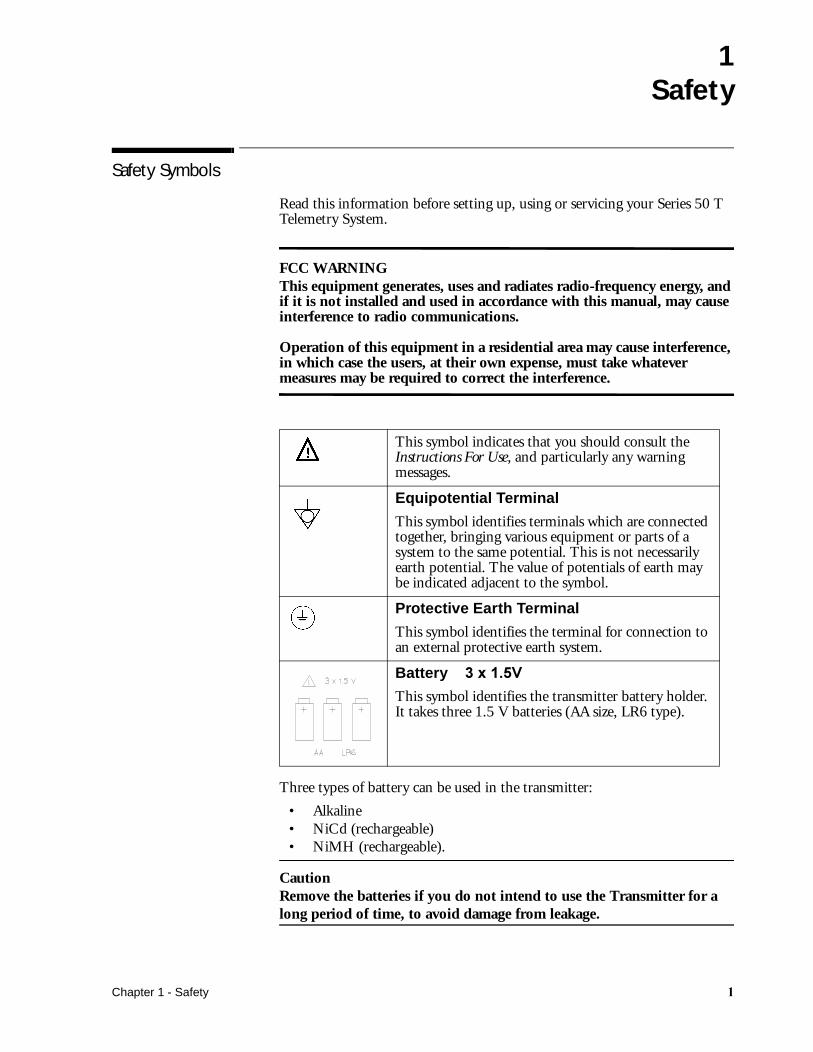
Three types of battery can be used in the transmitter:
• Alkaline• NiCd (rechargeable)• NiMH (rechargeable).
CautionRemove the batteries if you do not intend to use the Transmitter for a long period of time, to avoid damage from leakage.
This symbol indicates that you should consult the Instructions For Use, and particularly any warning messages.
Equipotential Terminal
This symbol identifies terminals which are connected together, bringing various equipment or parts of a system to the same potential. This is not necessarily earth potential. The value of potentials of earth may be indicated adjacent to the symbol.
Protective Earth Terminal
This symbol identifies the terminal for connection to an external protective earth system.
Battery ��������
This symbol identifies the transmitter battery holder. It takes three 1.5 V batteries (AA size, LR6 type).
Chapter 1 - Safety �
Patient Safety
Patient Safety
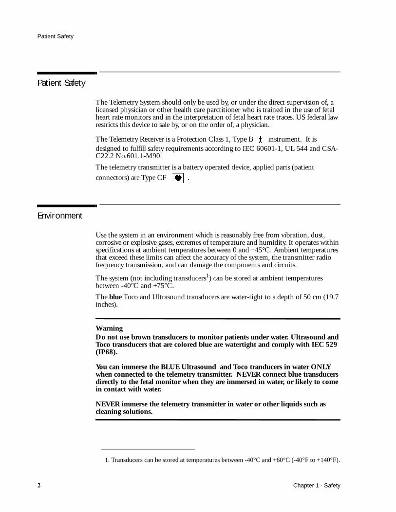
The Telemetry System should only be used by, or under the direct supervision of, a licensed physician or other health care parctitioner who is trained in the use of fetal heart rate monitors and in the interpretation of fetal heart rate traces. US federal law restricts this device to sale by, or on the order of, a physician.
The Telemetry Receiver is a Protection Class 1, Type B instrument. It is designed to fulfill safety requirements according to IEC 60601-1, UL 544 and CSA-C22.2 No.601.1-M90.
The telemetry transmitter is a battery operated device, applied parts (patient
connectors) are Type CF .
Environment
Use the system in an environment which is reasonably free from vibration, dust, corrosive or explosive gases, extremes of temperature and humidity. It operates within specifications at ambient temperatures between 0 and +45°C. Ambient temperatures that exceed these limits can affect the accuracy of the system, the transmitter radio frequency transmission, and can damage the components and circuits.
The system (not including transducers1) can be stored at ambient temperatures between -40°C and +75°C.
The blue Toco and Ultrasound transducers are water-tight to a depth of 50 cm (19.7 inches).
WarningDo not use brown transducers to monitor patients under water. Ultrasound and Toco transducers that are colored blue are watertight and comply with IEC 529 (IP68).
You can immerse the BLUE Ultrasound and Toco tranducers in water ONLY when connected to the telemetry transmitter. NEVER connect blue transducers directly to the fetal monitor when they are immersed in water, or likely to come in contact with water.
NEVER immerse the telemetry transmitter in water or other liquids such as cleaning solutions.
1. Transducers can be stored at temperatures between -40°C and +60°C (-40°F to +140°F).
� Chapter 1 - Safety

Protective Earth
Protective Earth
To protect hospital personnel and the patient, the cabinet must be grounded. Accordingly, the receiver is equipped with a 3-wire power cable which grounds it to the power line ground when plugged into an appropriate 3-wire receptacle. Do not use a 3-wire to 2-wire adapter with the receiver. Any interruption of the protective earth grounding will cause a potential shock hazard that could result in serious personal injury.
Whenever it is likely that the protection has been impaired, the receiver must be made inoperative and be secured against any unintended operation.
WarningCheck each time before use that the Telemetry System is in perfect working order and the receiver is properly grounded.
The patient cable must be positioned so that it does not come into contact with any other electrical equipment.
Before operation, make sure that the receiver is free from condensation. This can form when equipment is moved from one building to another, and is exposed to moisture and differences in temperature.
WarningPossible explosion hazard if used in the presence of flammable anesthetics.
Chapter 1 - Safety �
Maximum Input/Output Voltages
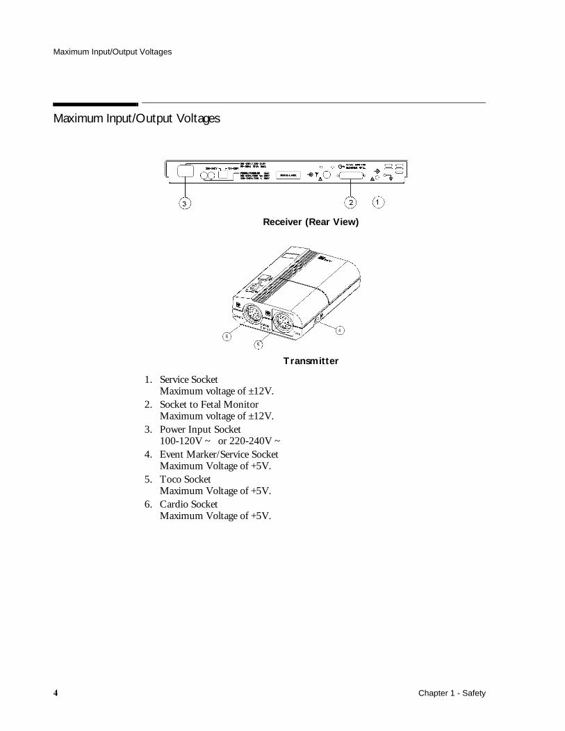
Maximum Input/Output Voltages
Receiver (Rear View)
Transmitter
1. Service SocketMaximum voltage of ±12V.
2. Socket to Fetal MonitorMaximum voltage of ±12V.
3. Power Input Socket100-120V ~ or 220-240V ~
4. Event Marker/Service SocketMaximum Voltage of +5V.
5. Toco SocketMaximum Voltage of +5V.
6. Cardio SocketMaximum Voltage of +5V.
� Chapter 1 - Safety

�Technical Specifications
Telemetry System (Receiver and Transmitter)
Power Requirements
The Telemetry System is set for the correct voltage at the factory, but before you connect power, ensure that the voltage switch is in the correct position for your country.
Operating Voltage: 100V - 120V~ or 220V - 240V (±10%).Line Frequency: 50 to 60Hz.Power Consumption: 19VA max.Battery Type: 3 x 1.5V (AA size).
Environment
The Telemetry System should be used in an environment which is reasonably free from vibration, dust, corrosive or explosive gases, extremes of temperature and humidity. It operates within specifications at ambient temperatures between 0 and 45°C . Ambient temperatures which exceed these limits can affect the accuracy of the Telemetry System, the Transmitter radio frequency transmission, and cause damage to the components and circuits.
Operating Temp: 0 to +45°C (32°F to 113°F).
Storage Temp1: -40 to +75°C (-40°F to 167°F).Relative Humidity: 5 to 95%.
Dimensions and Weight
Receiver Height: 50mm (2in).Width: 425mm (16.7in).Depth: 392mm (15.4in).Weight: 6.5kg (14.3 lb).
Transmitter Height: 122mm (4.8 in).Width: 85mm (3.3in).Depth: 40mm (1.6in).Weight: 200g (8 oz).(without transducers and batteries).
1. Excludes transducers. Transducers can be stored at temperatures between -40°C and +60°C (-40°F to +140°F).
Chapter 2 - Technical Specifications �

Telemetry System (Receiver and Transmitter)
Controls and Indicators
Channels and Frequencies
Over 160 different channels in the UHF Band (430-470 MHz) with 25 kHz/12.5 kHz channel spacing available. (See Chapter 11 for a list of the channels and frequencies available.)
Antenna Receiver
BNC Female input connector (standard 50 Ohms input). For standalone or connection to an antenna system.
Transmitter
Built-in Antenna in US and DECG transducer cables.
Inputs Receiver
• Equipotential Grounding Point.• Service Socket.
Receiver - Controls and Indicators
Description Type Color
Power On/Off Switch Push Button
Power On Light LED Green
Nurse Call Acknowledge/Volume Button Push Button
Nurse Call Light LED Yellow
Transmission INOP Light LED Yellow
Battery Low Light LED Yellow
Error Light LED Red
Transmitter - Controls and Indicators
Description Type Color
Power On/Off Switch Slide Switch
Power On Light LED Green
Nurse Call Push Button
Error Light LED Red
� Chapter 2 - Technical Specifications

Telemetry System (Receiver and Transmitter)
Transmitter
• Cardio socket for M1356A ultrasound transducer or the M1357A/M1364A DECG transducer.
• Toco socket for the M1355A Toco transducer or an IUP Transducer (CPJ840J5).
• Remote Event Marker and Service Socket.
Outputs Receiver
• 25 pin RS232 Socket for connecting the Fetal Monitor.
Input Sensitivity -118dBM
Output Power Transmitter
4 mW (USA)
2 mW (Europe)
1 mW (Japan)
Image Rejection >80 dB
Self-Test Facilities Self-test facilities include:
• Receiver Self Test: Tests the Receiver LF Part.• Transmitter Self Test: Tests the Transmitter LF Part.• Parameter Test: With the appropriate transducer connected to the
Transmitter, the monitoring mode (ultrasound/DECG or Toco/IUP) is tested from the Transmitter via Receiver to the connected Fetal Monitor.
Chapter 2 - Technical Specifications �
Transducers and Cables
Transducers and Cables
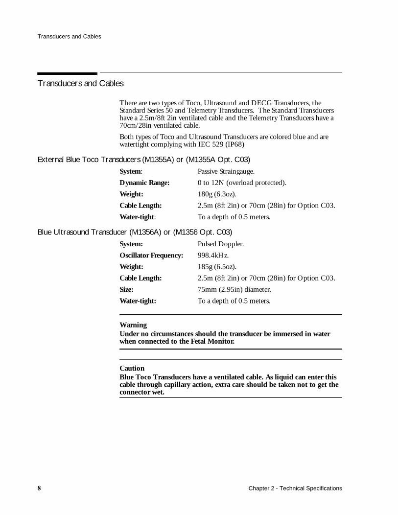
There are two types of Toco, Ultrasound and DECG Transducers, the Standard Series 50 and Telemetry Transducers. The Standard Transducers have a 2.5m/8ft 2in ventilated cable and the Telemetry Transducers have a 70cm/28in ventilated cable.
Both types of Toco and Ultrasound Transducers are colored blue and are watertight complying with IEC 529 (IP68)
External Blue Toco Transducers (M1355A) or (M1355A Opt. C03)
System: Passive Straingauge.
Dynamic Range: 0 to 12N (overload protected).
Weight: 180g (6.3oz).
Cable Length: 2.5m (8ft 2in) or 70cm (28in) for Option C03.
Water-tight: To a depth of 0.5 meters.
Blue Ultrasound Transducer (M1356A) or (M1356 Opt. C03)
System: Pulsed Doppler.
Oscillator Frequency: 998.4kHz.
Weight: 185g (6.5oz).
Cable Length: 2.5m (8ft 2in) or 70cm (28in) for Option C03.
Size: 75mm (2.95in) diameter.
Water-tight: To a depth of 0.5 meters.
WarningUnder no circumstances should the transducer be immersed in water when connected to the Fetal Monitor.
CautionBlue Toco Transducers have a ventilated cable. As liquid can enter this cable through capillary action, extra care should be taken not to get the connector wet.
� Chapter 2 - Technical Specifications
IUP Quartz Transducer (1290C #J05)
DECG Transducer (M1357A)
Input Impedance: >10M (di_erential, dc to 50/60Hz).
CMRR: >110dB (with patient cable, 51.5k/0.047_F imbalance atline frequency).
Noise: <4_Vp (referred to input with 25k).
Contact Potential Tolerance:_500mV.
Input Voltage Range: 20_Vp to 3mVp.
Patient Leakage Current: <10_Arms @ 120V/60Hz.
Patient Auxiliary Current: <0.1_A (dc).
Dielectric Strength: 2000Vrms (spark-gap protected).
Weight: 185g (6.5oz).
Cable Length: 2.5m (8ft 2in) or 70cm (28in) for Option C03.
DECG/MECG Patient Module (M1364A)
The patient module has a7-pin ECG connector into which you can plug either DECG cable (M1362A or M1362B) or MECG cable.
Overall length: 2706mm (+30, -100mm)
Length of free cable: 2618mm (+30, -100mm)
Weight: 120 grams
Size: 88x42x30mm
Socket: DECG or MECG connection
A short cable version of the M1364A patient module with a 70 cm (28 inch) cable is orderable as part number M1364-60003.
IUP Quartz Transducer (1290C #J05)
Dynamic Range: -50 to 300mmHg.
Sensitivity: 5_V/V/mmHg.
Non-linearity: whichever is greater:±1% of the reading OR±1mmHg.
Volume Displacement: 0.2mm3/100mmHg.
Weight: 180g (6.3oz).
Cable Length: 3m (9ft 10in).
Length: 37mm (1.5in).
Height: 21.7mm (0.9in).
Operating Temp: 15 to 40_C.
Chapter 2 - Technical Specifications
IUP Quartz Transducer (1290C #J05)
IUP Pressure Transducer (CPJ840J5)
Pressure range: -20 to + 300 mm Hg
Max. overpressure: 10,000 mm Hg
Sensitivity: 50µV/V/mm Hg
Resonance frequency: 300 Hz typical (transducer and dome)
Max. electrical excitation: 15 V DC or AC
Bridge resistance: 1000 Ohms (input and output)
Non-linearity and hysteresis: max. 0.5% of full scale
Zero balance: max. 0.15 mm Hg/°C
Operating temperature range:+10 to +50°C
Storage temperature range: -20 to +70°C
Isolation resistance: min. 1000 MOhms
Leakage current: max.1.5µA at 250V, 50 Hz
Weight: 24 grams (without cable)
Connector: Equipment specified
Remote Event Marker (15249A)
Length: 2.8m (9ft 2in).
Weight: 75g (2.65oz).
� Chapter 2 - Technical Specifications

�Tests and Error Messages
Testing the Receiver
To run the receiver self test:
1. Switch on the fetal monitor and its recorder.
2. Press the Power On/Off button to switch the receiver on.
3. When you switch on:
• The receiver On light (A) comes on.
• The nurse call light (B) and the battery low light (D) are lit for one second.
• The transmission INOP light (C) lights and stays lit until the transmitter is switched on.
• The telemetry lamp indicator on the fetal monitor lights, indicating telemetry monitoring mode.
• TELE is annotated on the fetal trace.
Chapter 3 - Tests and Error Messages ��
Testing the Transmitter
Testing the Transmitter
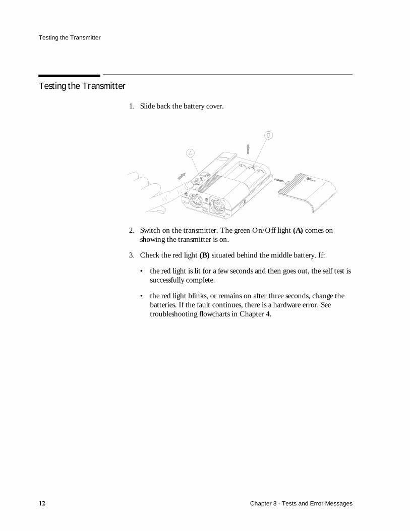
1. Slide back the battery cover.
2. Switch on the transmitter. The green On/Off light (A) comes on showing the transmitter is on.
3. Check the red light (B) situated behind the middle battery. If:
• the red light is lit for a few seconds and then goes out, the self test is successfully complete.
• the red light blinks, or remains on after three seconds, change the batteries. If the fault continues, there is a hardware error. See troubleshooting flowcharts in Chapter 4.
�� Chapter 3 - Tests and Error Messages
Testing the Parameter Signals
Testing the Parameter Signals
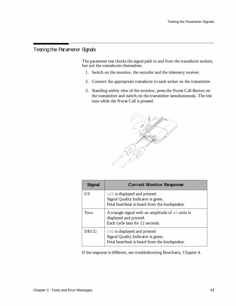
The parameter test checks the signal path to and from the transducer sockets, but not the transducers themselves.
1. Switch on the monitor, the recorder and the telemetry receiver.
2. Connect the appropriate transducer to each socket on the transmitter.
3. Standing within view of the monitor, press the Nurse Call Button on the transmitter and switch on the transmitter simultaneously. The test runs while the Nurse Call is pressed.
If the response is different, see troubleshooting flowcharts, Chapter 4.
Signal Correct Monitor Response
US 125 is displayed and printed.Signal Quality Indicator is green.Fetal heartbeat is heard from the loudspeaker.
Toco A triangle signal with an amplitude of 40 units is displayed and printed.Each cycle lasts for 12 seconds.
DECG 150 is displayed and printedSignal Quality Indicator is green.Fetal heartbeat is heard from the loudspeaker.
Chapter 3 - Tests and Error Messages ��
Error Messages
Error Messages
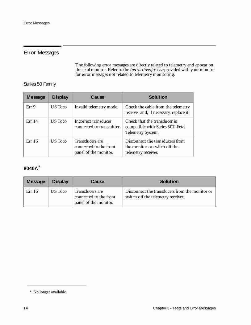
The following error messages are directly related to telemetry and appear on the fetal monitor. Refer to the Instructions for Use provided with your monitor for error messages not related to telemetry monitoring.
Series 50 Family
8040A*
Message Display Cause Solution
Err 9 US Toco Invalid telemetry mode. Check the cable from the telemetry receiver and, if necessary, replace it.
Err 14 US Toco Incorrect transducer connected to transmitter.
Check that the transducer is compatible with Series 50T Fetal Telemetry System.
Err 16 US Toco Transducers are connected to the front panel of the monitor.
Disconnect the transducers from the monitor or switch off the telemetry receiver.
Message Display Cause Solution
Err 16 US Toco Transducers are connected to the front panel of the monitor.
Disconnect the transducers from the monitor or switch off the telemetry receiver.
*. No longer available.
�� Chapter 3 - Tests and Error Messages

Error Messages
8041A*
Message Display Cause Solution
Signal indicator lamps flashing
Indicator Panel
Invalid telemetry mode.
Incorrect transducer connected into transmitter. (Only Ultrasound and Toco transducers can be used).
Transducers are connected to the front panel of the monitor.
Check the cable from the telemetry receiver and, if necessary, replace it.
Check that the transducer is compatible with Series 50T Fetal Telemetry System.
Disconnect the transducers from the monitor or switch off the telemetry receiver.
*. No longer available
Chapter 3 - Tests and Error Messages ��

Error Messages
�� Chapter 3 - Tests and Error Messages
4Troubleshooting
Solving General Problems
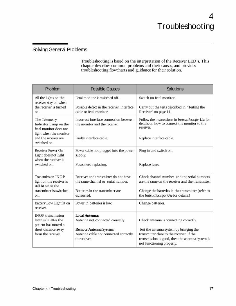
Troubleshooting is based on the interpretation of the Receiver LED’s. This chapter describes common problems and their causes, and provides troubleshooting flowcharts and guidance for their solution.
Problem Possible Causes Solutions
All the lights on the receiver stay on when the receiver is turned on.
Fetal monitor is switched off.
Possible defect in the receiver, interface cable or fetal monitor.
Switch on fetal monitor.
Carry out the tests described in “Testing the Receiver” on page 11.
The Telemetry Indicator Lamp on the fetal monitor does not light when the monitor and the receiver are switched on.
Incorrect interface connection between the monitor and the receiver.
Faulty interface cable.
Follow the instructions in Instructions for Use for details on how to connect the monitor to the receiver.
Replace interface cable.
Receiver Power On Light does not light when the receiver is switched on.
Power cable not plugged into the power supply.
Fuses need replacing.
Plug in and switch on.
Replace fuses.
Transmission INOP light on the receiver is still lit when the transmitter is switched on.
Receiver and transmitter do not have the same channel or serial number.
Batteries in the transmitter are exhausted.
Check channel number and the serial numbers are the same on the receiver and the transmitter.
Change the batteries in the transmitter (refer to the Instructions for Use for details.)
Battery Low Light lit on receiver.
Power in batteries is low. Change batteries.
INOP transmission lamp is lit after the patient has moved a short distance away form the receiver.
Local Antenna:Antenna not connected correctly.
Remote Antenna System:Antenna cable not connected correctly to receiver.
Check antenna is connecting correctly.
Test the antenna system by bringing the transmitter close to the receiver. If the transmission is good, then the antenna system is not functioning properly.
Chapter 4 - Troubleshooting ��
Solving General Problems
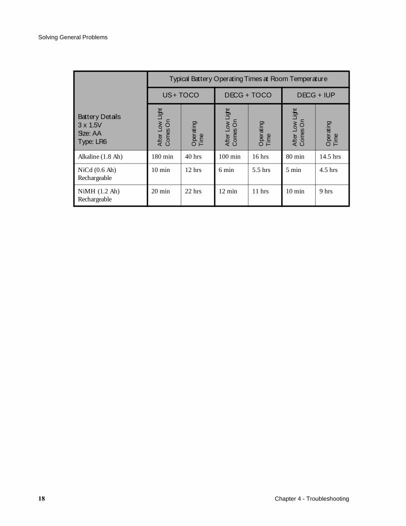
Battery Details3 x 1.5VSize: AAType: LR6
Typical Battery Operating Times at Room Temperature
US + TOCO DECG + TOCO DECG + IUP
Aft
er L
ow L
Ight
Com
es O
n
Ope
ratin
gT
ime
Aft
er L
ow L
ight
Com
es O
n
Ope
ratin
gT
ime
Aft
er L
ow L
ight
Com
es O
n
Ope
ratin
gT
ime
Alkaline (1.8 Ah) 180 min 40 hrs 100 min 16 hrs 80 min 14.5 hrs
NiCd (0.6 Ah)Rechargeable
10 min 12 hrs 6 min 5.5 hrs 5 min 4.5 hrs
NiMH (1.2 Ah)Rechargeable
20 min 22 hrs 12 min 11 hrs 10 min 9 hrs
�� Chapter 4 - Troubleshooting

Solving General Problems
No LEDs Lit on Receiver (continued overleaf)
Figure 1 Troubleshooting: No LED’s Lit on Receiver
Chapter 4 - Troubleshooting �

Solving General Problems
Figure 1 Troubleshooting: No LED’s Lit on Receiver (continued from previous page)
� Chapter 4 - Troubleshooting

Solving General Problems
Not all Receiver LEDs are Lit
Figure 2 Troubleshooting Receiver LEDs
Yellow LED Remains Lit
Figure 3 Troubleshooting: Yellow LED stays on
Chapter 4 - Troubleshooting ��
Solving General Problems
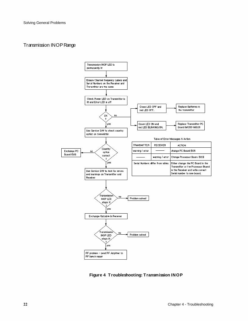
Transmission INOP Range
Figure 4 Troubleshooting: Transmission INOP
�� Chapter 4 - Troubleshooting
Solving General Problems
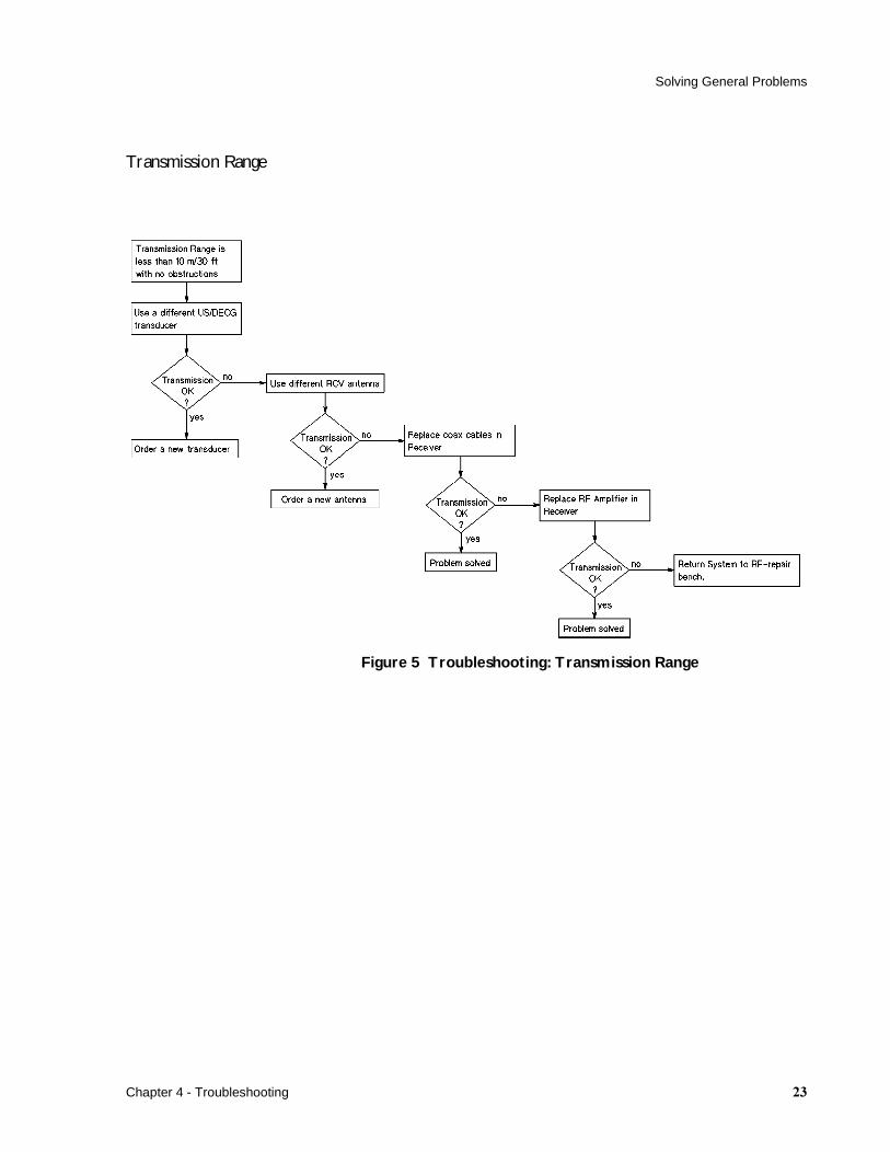
Transmission Range
Figure 5 Troubleshooting: Transmission Range
Chapter 4 - Troubleshooting ��

Solving General Problems
Transducer Mode Not Detected
Figure 6 Troubleshooting: Transducer not detected
�� Chapter 4 - Troubleshooting
Cardio Channel
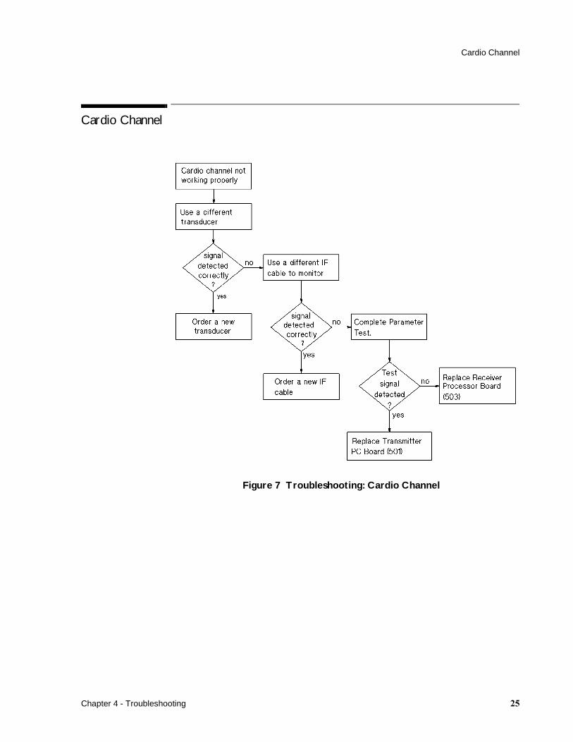
Cardio Channel
Figure 7 Troubleshooting: Cardio Channel
Chapter 4 - Troubleshooting ��
TOCO Channel
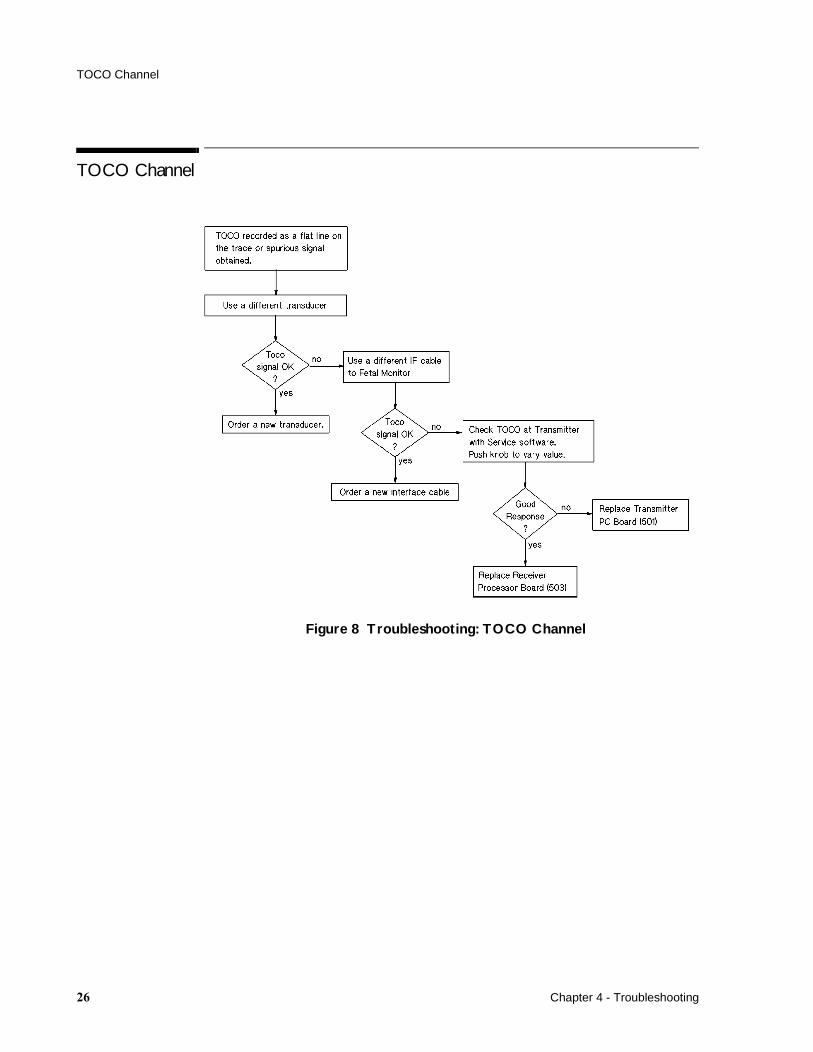
TOCO Channel
Figure 8 Troubleshooting: TOCO Channel
�� Chapter 4 - Troubleshooting
FMP
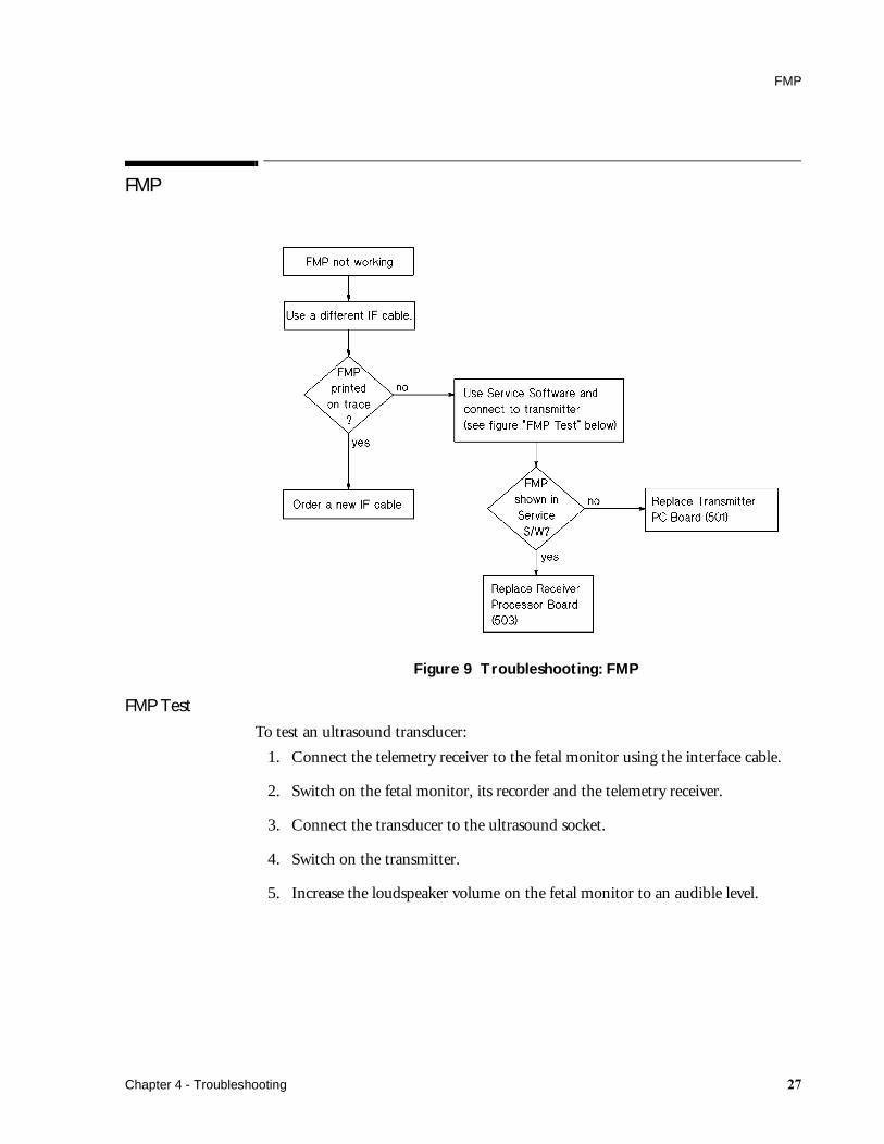
FMP
Figure 9 Troubleshooting: FMP
FMP Test
To test an ultrasound transducer:
1. Connect the telemetry receiver to the fetal monitor using the interface cable.
2. Switch on the fetal monitor, its recorder and the telemetry receiver.
3. Connect the transducer to the ultrasound socket.
4. Switch on the transmitter.
5. Increase the loudspeaker volume on the fetal monitor to an audible level.
Chapter 4 - Troubleshooting ��
FMP
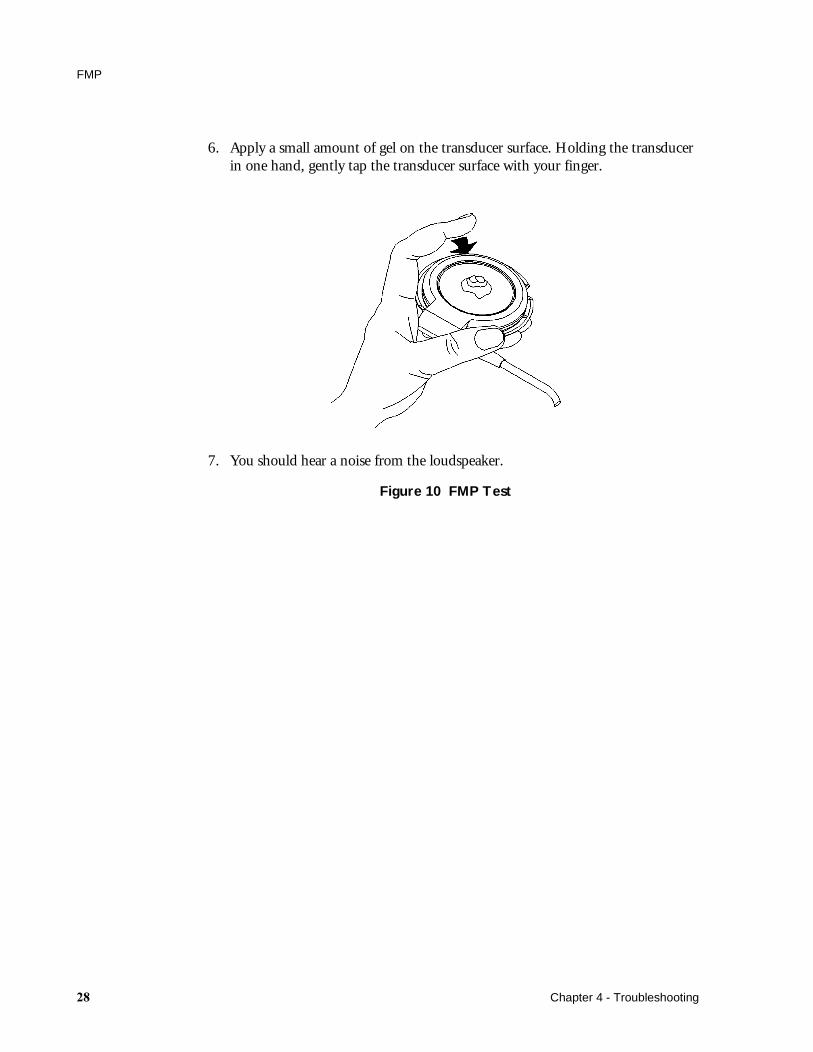
6. Apply a small amount of gel on the transducer surface. Holding the transducer in one hand, gently tap the transducer surface with your finger.
7. You should hear a noise from the loudspeaker.
Figure 10 FMP Test
�� Chapter 4 - Troubleshooting
Event Marker
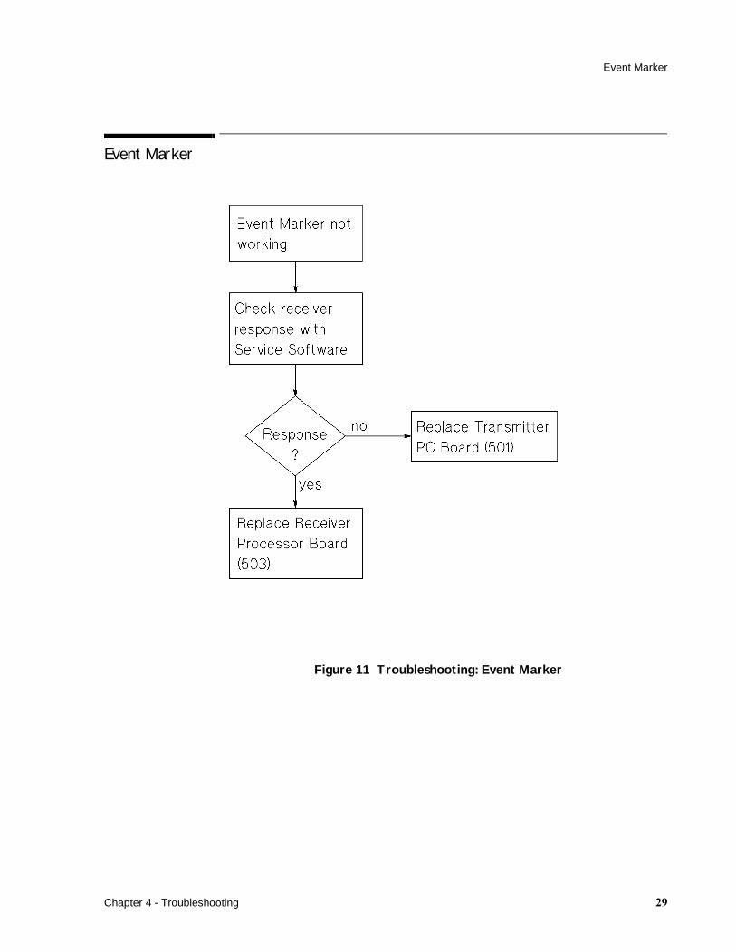
Event Marker
Figure 11 Troubleshooting: Event Marker
Chapter 4 - Troubleshooting �
Nurse Call
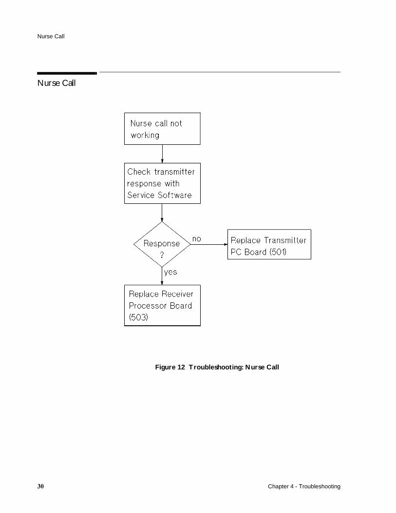
Nurse Call
Figure 12 Troubleshooting: Nurse Call
� Chapter 4 - Troubleshooting

�Interfacing to a Fetal Monitor
The Fetal Monitor Interface on the Telemetry Receiver allows digital and analog ouputs to the Monitor. The following table lists the signals at each pin.
Key: (L) means Logic signal is low (0 Volts).
Note— Status ouputs PIN 5, PIN 19, PIN 20 and PIN 21 have open collector outputs, all other status signals have 5V HCMOS level outputs.
� � ��� ������
1 Not connected.
2 Not connected.
3 Not connected.
4 Not connected.
5 nTELEon Receiver on (L).
6 Not connected.
7 nINOP DECG inop (L).
8 nDECG DECG Mode (L).
9 Not connected.
10 nUS US Mode (L).
11 Not connected.
12 nIUP IUP Mode (L).
13 nTOCO TOCO External Mode (L).
14 HR US LF or ECG Signal.
15 TOCO TOCO/IUP signal.
16 - Not connected.
17 Gnd Analog Analog Ground.
18 Gnd
19 nMarker Tele-Marker on (L).
20 nFMPon Tele-FMP on (L) if FMP available.
21 nFMPsig Tele-Fetal movement on (L)
22 - Not connected
23 IF ID �������Shorted to ground with HP 8040/41A and older Series 50 Telemetry Interface. Open for enhanced Series 50 Telemetry.
24 Gnd
25 - Not connected.
Chapter 5 - Interfacing to a Fetal Monitor ��

�� Chapter 5 - Interfacing to a Fetal Monitor
�Using the Service Software
Prerequisites
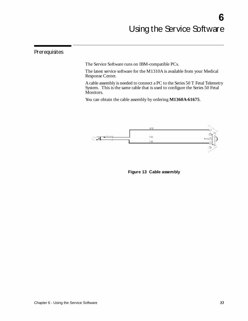
The Service Software runs on IBM-compatible PCs.
The latest service software for the M1310A is available from your Medical Response Center.
A cable assembly is needed to connect a PC to the Series 50 T Fetal Telemetry System. This is the same cable that is used to configure the Series 50 Fetal Monitors.
You can obtain the cable assembly by ordering M1360A-61675.
Figure 13 Cable assembly
Chapter 6 - Using the Service Software ��

Running the Service Software Program
Running the Service Software Program
To run the Service Software Program, complete the following:
The example above runs the program and uses COM2.
Note— If you have problems running the program in WINDOWS exit WINDOWS and run the program in DOS.
Some communications programs like ‘ ‘ llremote’’ can cause problems to start tweetsrv.exe. In this case, disconnect to release COM-port or exit WINDOWS.
Run tweetsrv.exe
You can add /? for HELP how to run
/1 for COM1 (default)
/2 for COM2
/3 for COM3
/4 for COM4
Example :/tweetsrv.exe /2
�� Chapter 6 - Using the Service Software

Using the Service Program
Using the Service Program
When the program has been loaded onto your PC, the main menu is displayed. (If the menu is not displayed an error message is displayed along the bottom of the screen).
Main Menu
--------------------------------------------------------------------------------------
--M1310A Service Software Rev.A.xx.xx--
MAIN MENU
_ Program S/N to Transmitter
_ Program S/N to Receiver
_ Power On Selftest
_ Show last errors/warnings
_ Check Transmitter
_ Check Receiver
_ Read SerNum and Revisions
_ Reset Serial Number
_ Read country information
_ EXIT
--------------------------------------------------------------------------------------
Select with >cursor keys < up >, < down >,< enter >
--------------------------------------------------------------------------------------
Chapter 6 - Using the Service Software ��
Using the Service Program
Program S/N toTransmitter
Programs the Serial Number to the Transmitter (if no Serial Number is present on the Transmitter). This feature is needed when the Transmitter Printed Circuit Board is exchanged.
Follow the steps as the program requests.
When moving the service connector from one device to the other, a "SIO RCV error" may be displayed. This is due to the PC’s serial interface circuitry and can be ignored.
If a Serial Number needs to be RESET, contact the factory Technical Marketing Engineer to get RESET-CODE needed to RESET the Serial Number.
Program S/N toReceiver
Programs the Serial Number to the Receiver (if no Serial Number is present on the Receiver). This feature is needed when Receiver-PC-Bd. is exchanged.
Follow the steps as the program requests.
When moving the service connector from one device to the other, a "SIO RCV error" may be displayed. This is due to the PC’s serial interface circuitry and can be ignored.
If a Serial Number needs to be RESET, contact factory Technical Marketing Engineer to get RESET-CODE to RESET the Serial Number.
Power On Selftest The PC acts as a Terminal. The Transmitter or Receiver connected to the PC must be switched OFF and then ON. The PC displays the Start-up messages from the connected Transmitter or Receiver.
Show last errors/warnings
Shows the summary of the received Errors and Warnings.
Check Transmitter Provides a Transmitter check of the following:
• detected modes• status bits• TOCO value
Check Receiver Provides a Receiver check of the following:
• detected modes• status bits• TOCO value• RF field strength
Read SerNum andRevisions
When selected from the Main Menu, this sub-menudisplays:
• Software Revision• Serial Protocol Revision• Serial Number (S/N)
�� Chapter 6 - Using the Service Software
Using the Service Program
Reset Serial Number This feature is only available for HP Service Personnel. It allows you to reset the Serial Number on the Transmitter or Receiver Board if the Serial Number was programmed incorrectly.To use this section a Reset-Code from a factory Technical Marketing Engineer is needed.
The Technical Marketing Engineer requires the following information:
• Serial Number (S/N)• Transmitter OR Receiver• Reason for RESET request
The Technical Marketing Engineer will provide you with:
The RESET-CODE.
CautionNever erase the Serial Number from both the transmitter and the receiver, as this status is not recoverable and requires factory assistance.
Read countryinformation
Displays the country information:
• International or• France or• Japan• The RF-bandwidth
25 kHz ++or++ 12.5 kHz• and when JAPAN
Japan ID-code
EXIT Exits the program.
Chapter 6 - Using the Service Software ��

Using the Service Program
�� Chapter 6 - Using the Service Software

�Replacing Parts
This chapter identifies the boards and replacement parts, giving their part numbers, and lists the tools you’ll need to service the Series 50 T Fetal Telemetry System.
For most service tasks, it is not necessary to remove parts, and you should only dismantle the Telemetry Receiver and Transmitter as far as is necessary.
WarningElectrical power is dangerous. Before removing any parts from the Receiver, the power to the Receiver must be disconnected.
CautionStatic electricity will damage sensitive electrical circuitry. Ensure you are adequately grounded before touching any circuit board or its associated components.
Ordering Parts
To order a part, contact your local Philips Sales/Service Office, quoting the part number listed in the tables. To order a part not listed in the tables, give the following information:
• The model number of the Telemetry System.• The complete serial number of the Telemetry System.• A description of the part, including its function and location.
CautionOccasionally, as well as markings indicating manufacture by Philips, electronic components will carry standard commercial identification numbers. These components have been selected to meet specific operational criteria. Using components purchased through normal commercial channels may result in degradation of the operation performance or the reliability of the Receiver or Transmitter.
Chapter 7 - Replacing Parts �
Service Tools
Service Tools
You should have available all the boards and parts listed in the following tables, plus the following tools:
• Small crosshead screwdriver.• Medium slothead screwdriver.• Large crosshead screwdriver.• Box screwdriver (HBA).• Spanner (M6 and M5)• Digital Volt Meter.• Small pincers or tweezers (useful, but not essential).
Lists of Parts
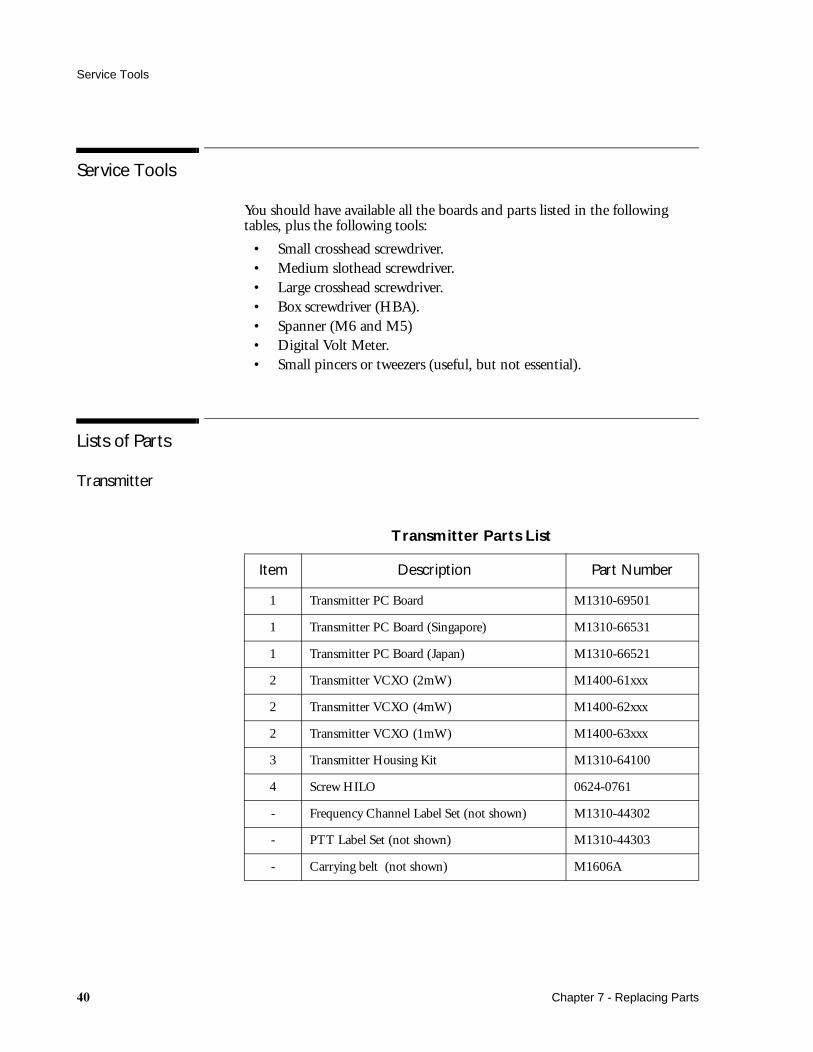
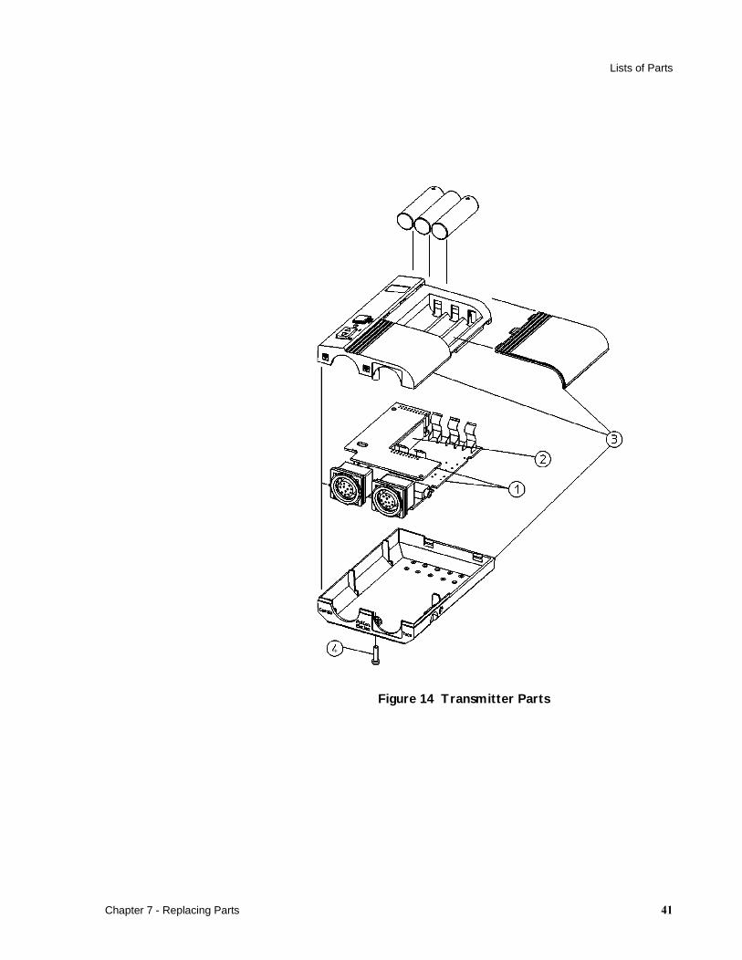
Transmitter
Transmitter Parts List
Item Description Part Number
1 Transmitter PC Board M1310-69501
1 Transmitter PC Board (Singapore) M1310-66531
1 Transmitter PC Board (Japan) M1310-66521
2 Transmitter VCXO (2mW) M1400-61xxx
2 Transmitter VCXO (4mW) M1400-62xxx
2 Transmitter VCXO (1mW) M1400-63xxx
3 Transmitter Housing Kit M1310-64100
4 Screw HILO 0624-0761
- Frequency Channel Label Set (not shown) M1310-44302
- PTT Label Set (not shown) M1310-44303
- Carrying belt (not shown) M1606A
� Chapter 7 - Replacing Parts
Lists of Parts
Figure 14 Transmitter Parts
Chapter 7 - Replacing Parts ��
Lists of Parts
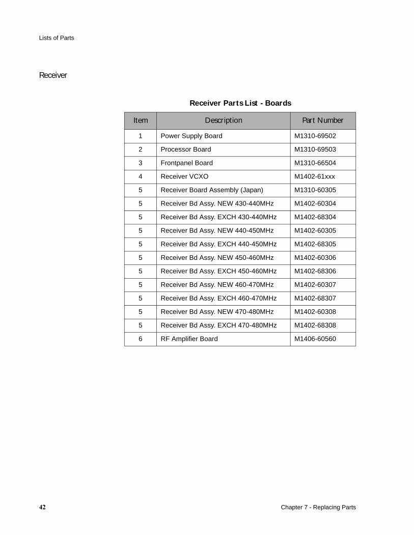
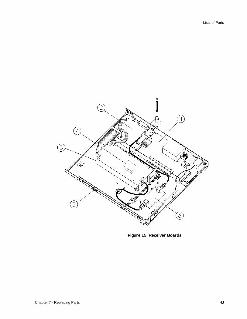
Receiver
Receiver Parts List - Boards
Item Description Part Number
1 Power Supply Board M1310-69502
2 Processor Board M1310-69503
3 Frontpanel Board M1310-66504
4 Receiver VCXO M1402-61xxx
5 Receiver Board Assembly (Japan) M1310-60305
5 Receiver Bd Assy. NEW 430-440MHz M1402-60304
5 Receiver Bd Assy. EXCH 430-440MHz M1402-68304
5 Receiver Bd Assy. NEW 440-450MHz M1402-60305
5 Receiver Bd Assy. EXCH 440-450MHz M1402-68305
5 Receiver Bd Assy. NEW 450-460MHz M1402-60306
5 Receiver Bd Assy. EXCH 450-460MHz M1402-68306
5 Receiver Bd Assy. NEW 460-470MHz M1402-60307
5 Receiver Bd Assy. EXCH 460-470MHz M1402-68307
5 Receiver Bd Assy. NEW 470-480MHz M1402-60308
5 Receiver Bd Assy. EXCH 470-480MHz M1402-68308
6 RF Amplifier Board M1406-60560
�� Chapter 7 - Replacing Parts
Lists of Parts
Figure 15 Receiver Boards
Chapter 7 - Replacing Parts ��

Lists of Parts
Receiver Parts List
Item Description Part Number
1 Coax Cable Assembly 8120-6413
2 Flat Cable Assembly (48 pin) 8120-6414
3 Antenna 450-512 MHz 0950-2028
3 Antenna 406-450 MHz 0950-2029
4 BNC-Connector 90 deg. 1250-0076
5 Power SW Manipulator 5040-9317
6 Power SW Knob 5040-1203
7 Receiver Housing Kit M1310-64551
8 Fuse T300mA/UL 2110-0044
8 Fuse L125/IEC 2110-0488
9 Fuse Holder Cap/UL 2110-0565
9 Fuse Holder Cap/IEC 2110-0567
10 Ground Pin 1251-5964
11 Washer 2190-0676
12 Plastic Plug for Receiver Top 6960-0016
- Foot for Receiver Housing (not shown) 5041-4264
- IF Cable to Fetal Monitor (not shown) M1310-61601
- Receiver Wallmounting Kit (not shown) M1310-64150
�� Chapter 7 - Replacing Parts

Lists of Parts
Figure 16 Receiver Parts
Transducers
��������� ����������
Toco with 70cm Cable M1355-69013
US with 70cm Cable M1356-69013
DECG with 70cm Cable M1364-60003
Chapter 7 - Replacing Parts ��

Dismantling the Transmitter
Dismantling the Transmitter
1. Remove the batteries from the battery compartment.
2. Turn the transmitter upside down and, using a small crosshead screwdriver, undo the screw.
Removing screw on Transmitter Housing
3. Turn the transmitter over and lift off the top of the transmitter housing.
Removing Top of Transmitter Housing
�� Chapter 7 - Replacing Parts

Transmitter Processor Board
Transmitter Processor Board
To remove the Transmitter Processor Board, follow the instructions for dismantling the transmitter then:
1. Remove the complete assembly from housing by lifting it out from the cardio connector side first.
Lifting out Assembly.
2. With your hand apply gentle upward pressure in a rocking motion to seperate the top board from the bottom board.
3. Remove the Cardio and Toco socket rings (A).
Separating the Boards.
Chapter 7 - Replacing Parts ��
Transmitter Processor Board
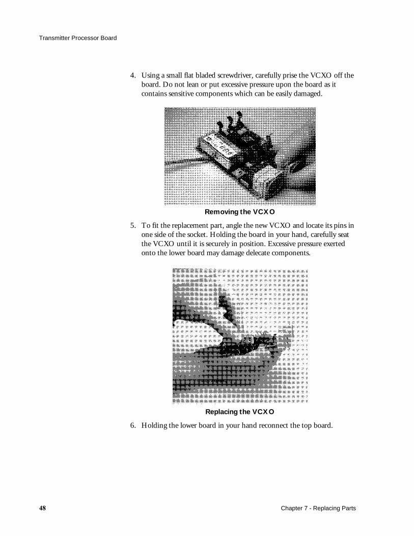
4. Using a small flat bladed screwdriver, carefully prise the VCXO off the board. Do not lean or put excessive pressure upon the board as it contains sensitive components which can be easily damaged.
Removing the VCXO
5. To fit the replacement part, angle the new VCXO and locate its pins in one side of the socket. Holding the board in your hand, carefully seat the VCXO until it is securely in position. Excessive pressure exerted onto the lower board may damage delecate components.
Replacing the VCXO
6. Holding the lower board in your hand reconnect the top board.
�� Chapter 7 - Replacing Parts

Transmitter Processor Board
7. Replace connector rings to the Cardio and Toco sockets (A).8. Ensure that the on/off switch manipulator (B) is in the off position.9. Insert board into housing at an angle, Toco side first.
Re-Assembling the Transmitter
10. Ensure power on/off switch is at 0 (C).
Replacing the Housing
11. Replace the top part of the housing and snap the 2 parts together.12. Check On/Off switch mechanism is in the O (off) position.13. Screw together carefully (do not fully tighten).14. Replace the batteries.15. Switch on and ensure that the green On LED is lit. Also check the red
LED inside the battery compartment by lifting the battery cover (the red LED is situated behind the middle battery).
16. Use the service software to set the transmitter serial number. The serial number should be the same as the number on the label on the rear of the transmitter.
Chapter 7 - Replacing Parts �
Transmitter VCXO
Transmitter VCXO
To remove the Transmitter VCXO, follow the instructions at the beginning of this chapter for dismantling the Transmitter then:
1. Take out complete assembly from housing by lifting from the cardio side.
2. Lift top board from bottom board by lifting from the cardio side.
3. Remove the Cardio and Toco socket rings.
4. Seperate the top board from the bottom board.
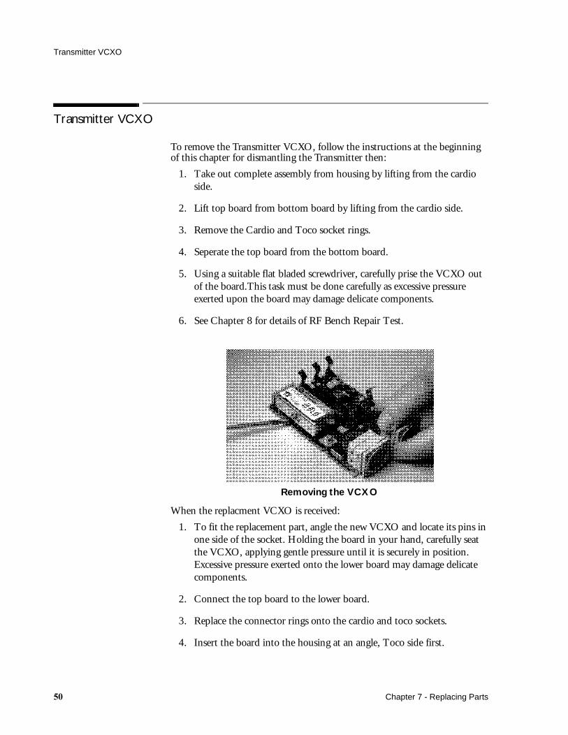
5. Using a suitable flat bladed screwdriver, carefully prise the VCXO out of the board.This task must be done carefully as excessive pressure exerted upon the board may damage delicate components.
6. See Chapter 8 for details of RF Bench Repair Test.
Removing the VCXO
When the replacment VCXO is received:
1. To fit the replacement part, angle the new VCXO and locate its pins in one side of the socket. Holding the board in your hand, carefully seat the VCXO, applying gentle pressure until it is securely in position. Excessive pressure exerted onto the lower board may damage delicate components.
2. Connect the top board to the lower board.
3. Replace the connector rings onto the cardio and toco sockets.
4. Insert the board into the housing at an angle, Toco side first.
� Chapter 7 - Replacing Parts
Dismantling the Receiver
5. Check switch mechanism is set at O (off).
6. Connect the top housing to the bottom housing and snap the two parts together.
7. Screw the housing together carefully (do not press hard).
8. Replace the batteries.
9. Switch on and ensure that the green On LED is lit. Also check the red LED inside the battery compartment (situated behind the middle battery) by lifting the battery cover.
Dismantling the Receiver
To dismantle the Receiver:
1. Turn the Receiver off and disconnect from power supply.
2. Remove antenna.
3. Remove 4 screws (A).
4. Slide top cover from back to front until it stops.
5. Lift off.
Chapter 7 - Replacing Parts ��

Dismantling the Receiver
Dismantling the Receiver
Note— Cases with spacers are not interchangable with those earlier models that do not have them fitted.
�� Chapter 7 - Replacing Parts
Power Supply Board
Power Supply Board
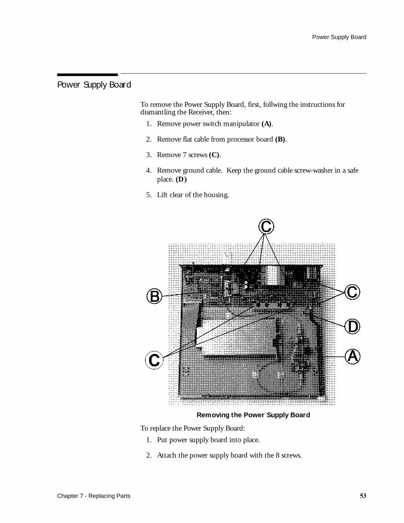
To remove the Power Supply Board, first, follwing the instructions for dismantling the Receiver, then:
1. Remove power switch manipulator (A).
2. Remove flat cable from processor board (B).
3. Remove 7 screws (C).
4. Remove ground cable. Keep the ground cable screw-washer in a safe place. (D)
5. Lift clear of the housing.
Removing the Power Supply Board
To replace the Power Supply Board:
1. Put power supply board into place.
2. Attach the power supply board with the 8 screws.
Chapter 7 - Replacing Parts ��

Power Supply Board
3. Reconnect the ground cable with screw and washer.
4. Reconnect the flat cable from the processor board.
5. Connect power switch manipulator.
Processor Board
To remove the Processor Board, first follow the instructions for dismantling the Receiver, then:
Removing the Processor Board
1. Remove the flat cable to the Power Supply Board (A).
2. Remove the cable to the Front Panel Board (B).
3. Remove the flat cable connector (C).
4. Using a M6 spanner, remove the coax cable (D).
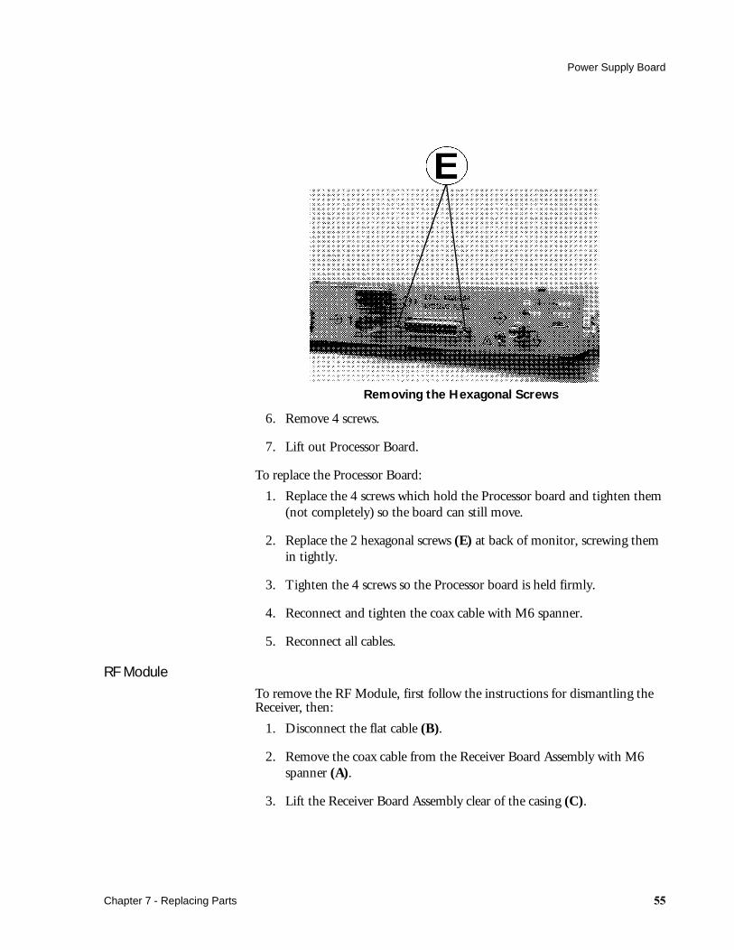
5. Using a M5 spanner, remove the 2 hexagonal screws (E) at the 25 pin D type connector. (See next picture).
�� Chapter 7 - Replacing Parts
Power Supply Board
Removing the Hexagonal Screws
6. Remove 4 screws.
7. Lift out Processor Board.
To replace the Processor Board:
1. Replace the 4 screws which hold the Processor board and tighten them (not completely) so the board can still move.
2. Replace the 2 hexagonal screws (E) at back of monitor, screwing them in tightly.
3. Tighten the 4 screws so the Processor board is held firmly.
4. Reconnect and tighten the coax cable with M6 spanner.
5. Reconnect all cables.
RF Module
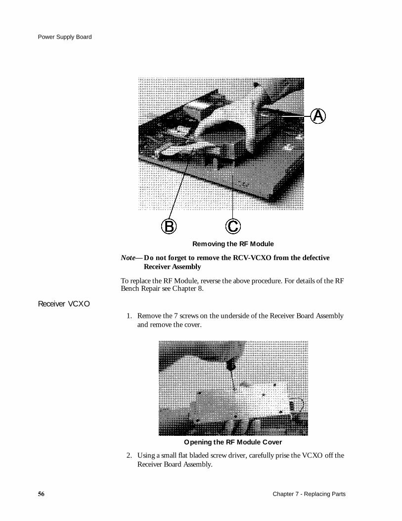
To remove the RF Module, first follow the instructions for dismantling the Receiver, then:
1. Disconnect the flat cable (B).
2. Remove the coax cable from the Receiver Board Assembly with M6 spanner (A).
3. Lift the Receiver Board Assembly clear of the casing (C).
Chapter 7 - Replacing Parts ��
Power Supply Board
Removing the RF Module
Note— Do not forget to remove the RCV-VCXO from the defective Receiver Assembly
To replace the RF Module, reverse the above procedure. For details of the RF Bench Repair see Chapter 8.
Receiver VCXO
1. Remove the 7 screws on the underside of the Receiver Board Assembly and remove the cover.
Opening the RF Module Cover
2. Using a small flat bladed screw driver, carefully prise the VCXO off the Receiver Board Assembly.
�� Chapter 7 - Replacing Parts

Power Supply Board
3. When fitting the replacement VCXO, angle the new part and locate its pins in one side of the socket. Carefully seat the VCXO, applying gentle pressure until it is securely in position.
Fitting the VCXO to RF Module
To replace the RF module, reverse the above procedure.
RF Amplifier
To remove the RF Amplifier, first follow the instructions for dismantling the Receiver, then:
1. Remove the 3 screws that hold the RF Amplifier Board.
2. Disconnect the coax cables.
3. Lift the RF Amplifier clear of the casing.
To replace the RF Amplifier, reverse the above procedure.
Display Board
To remove the Display Board, first follow the instructions for dismantling the Receiver, then:
1. Remove the small flat cable from the Display Board.
2. Remove the 3 screws which hold the Display Board.
3. Lift the Display Board clear.
To replace the Display Board, reverse the above procedure.
Chapter 7 - Replacing Parts ��
Fuses
Fuses
The fuse values are printed beside the mains socket:
For 100-120V Line Voltage T300mA 250V UL
For 220-240V Line Voltage T125 L 250V IEC
( = alternating current)
For part numbers see the Receiver parts list.
To replace the fuses:
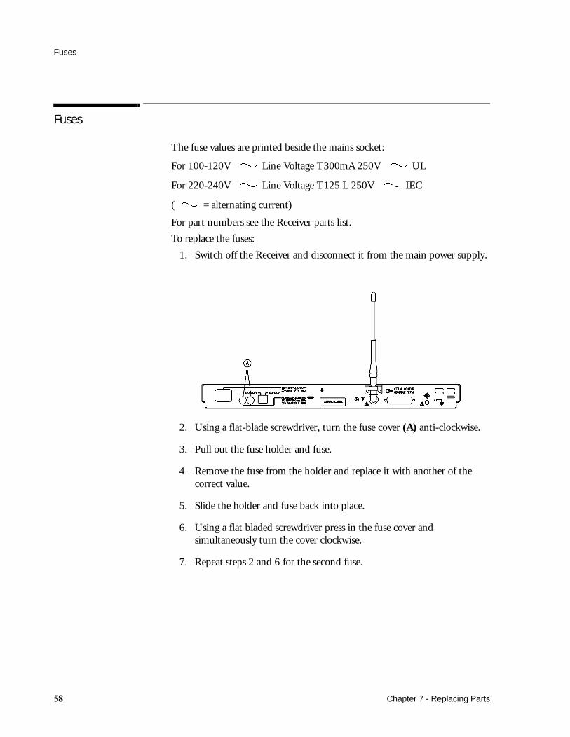
1. Switch off the Receiver and disconnect it from the main power supply.
2. Using a flat-blade screwdriver, turn the fuse cover (A) anti-clockwise.
3. Pull out the fuse holder and fuse.
4. Remove the fuse from the holder and replace it with another of the correct value.
5. Slide the holder and fuse back into place.
6. Using a flat bladed screwdriver press in the fuse cover and simultaneously turn the cover clockwise.
7. Repeat steps 2 and 6 for the second fuse.
�� Chapter 7 - Replacing Parts

RF Bench Repair
Introduction
RF Bench Repair should be performed when the low-frequency sections of the Series 50 T Transmitter and Receiver have passed the tests in the Troubleshooting Flowcharts Chapter 4 with no problems. RF associated Transmitter and Receiver problems should be identified and resolved using the RF Bench Test.
CautionStatic electricity will damage sensitive electrical circuitry. Ensure you are adequately grounded before touching any circuit board or its associated components.
What You Need
The following equipment is required to perform the test and repair:
The goal of the RF Bench Test is to find out which of the following sections is defective:
Transmitter VCXO (M1400-6xxxx)Receiver Preamplifier Board (M1406-60560)Receiver Assembly (M1402-6x30x)Receiver VCXO (M1402-61xxx)If the operating range is decreased or no transmission is possible, the following tests given in this chapter should be performed.
Equipment Requirements Example
Oscilloscope >10MHz, 100 mV min HP54601A
Active Probe 500 MHz (min.) HP1120A
Spectrum Analyzer 100 Hz to 500 MHz (min)Freq. Accur.:<2ppm
HP8568B
Signal Generator 500 MHz (min.) HP8640B
2 BNC Cables 50 Ohms0.7 to 1.5m long
HP10503A
BNC Adapter 50 Ohms 1250-0080
AC coupler 0.18uF, 200V 10240B
Chapter 8 - RF Bench Repair �

Transmitter VCXO Test
Transmitter VCXO Test
1. Open the battery compartment of the Transmitter and remove the batteries.
2. Turn over the transmitter and remove the screw.
3. Pull up the housing top and lift out the Transmitter Board Assembly from the bottom housing.
4. Place the Transmitter Board Assembly into housing top again and load the batteries. Ensure the power switch manipulator is in the off position.
5. Switch on the Transmitter.
Note— Ensure that no Transducers are connected to the Cardio or Toco Sockets.
6. Connect an Oscilloscope ( 1 MOhms input impedance).
7. Ground to the marked ground point and the probe to position.
Figure 17 Transmitter VCXO Test
� Chapter 8 - RF Bench Repair
Transmitter VCXO Test
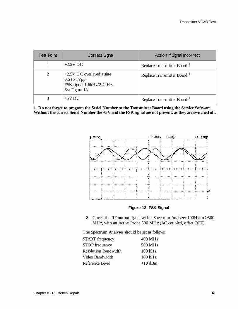
Figure 18 FSK Signal
8. Check the RF output signal with a Spectrum Analyzer 100Hz to ≥500 MHz, with an Active Probe 500 MHz (AC coupled, offset OFF).
The Spectrum Analyser should be set as follows:
START frequency 400 MHzSTOP frequency 500 MHzResolution Bandwidth 100 kHzVideo Bandwidth 100 kHzReference Level +10 dBm
Test Point Correct Signal Action If Signal Incorrect
1 +2.5V DC Replace Transmitter Board.1
2 +2.5V DC overlayed a sine0.5 to 1VppFSK-signal 1.6kHz/2.4kHz.See Figure 18.
Replace Transmitter Board.1
3 +5V DC Replace Transmitter Board.1
1. Do not forget to program the Serial Number to the Transmitter Board using the Service Software. Without the correct Serial Number the +5V and the FSK signal are not present, as they are switched off.
Chapter 8 - RF Bench Repair ��

Transmitter VCXO Test
Figure 19 RF Output Signal
9. Check the modulation. To check the modulation the Spectrum Analyzer should be set as follows:
CENTER frequency The channel frequency of the TransmitterFrequency Span 50 kHzResolution Bandwidth 300 HzVideo Bandwidth 300 HzReference Level +10 dBm
Test Point Correct Signal Action if signal incorrect
4 Peak Level >-6dBm Replace Transmitter VCXO
Test Point Correct Signal Action if signal incorrect
5 Peak Level >-12dBm Replace Transmitter Processor board 501
�� Chapter 8 - RF Bench Repair
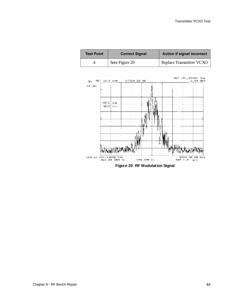
Transmitter VCXO Test
Figure 20 RF Modulation Signal
!������� "�������� ��� #�����$�� ������������
4 Seee Figure 20 Replace Transmitter VCXO
Chapter 8 - RF Bench Repair ��
Receiver Preamplifier Test
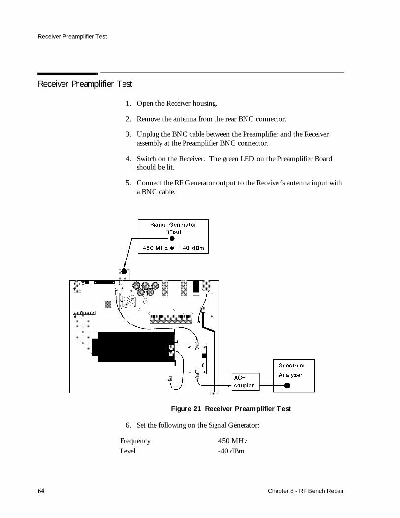
Receiver Preamplifier Test
1. Open the Receiver housing.
2. Remove the antenna from the rear BNC connector.
3. Unplug the BNC cable between the Preamplifier and the Receiver assembly at the Preamplifier BNC connector.
4. Switch on the Receiver. The green LED on the Preamplifier Board should be lit.
5. Connect the RF Generator output to the Receiver’s antenna input with a BNC cable.
Figure 21 Receiver Preamplifier Test
6. Set the following on the Signal Generator:
Frequency 450 MHzLevel -40 dBm
�� Chapter 8 - RF Bench Repair

Receiver Assembly Test
7. Using an AC Coupler, connect the Preamplifier’s output to the input of the Spectrum Analyzer. The AC Coupler prevents the Spectrum Analyser input from receiving 21 V DC.
The Spectrum Analyser should be set as follows:START frequency 400 MHzSTOP frequency 500 MHzResolution Bandwidth 100 kHzVideo Bandwidth 100 kHzReference Level -10 dBmThe Spectrum Analyser measurement must be:
Frequency 450 MHzLevel > - 32 dBmIf this measurement is correct, complete Receiver Assembly Test.
8. Remove the BNC connector from the Preamplifier input and connect this cable to the Spectrum Analyzer.
The Spectrum Analyser measurement must be:
Frequency 450 MHzLevel > - 46 dBm
9. If this measurement is correct, replace the Preamplifier Board. If this measurement is not correct, replace the Coax cable. If this does not solve the problem, replace the Receiver Processor Board (503).
Receiver Assembly Test
1. Remove the flat cable and coax cable from the Receiver Assembly.
2. Pull out and turn over the Receiver Assembly and undo all 7 screws.
3. Lift up the top cover of the Receiver Assembly and connect the flat cable again.
Chapter 8 - RF Bench Repair ��

Receiver VCXO Test
4. Switch on the Receiver. The green LED on the Receiver Assembly should flicker. Check the +5V, -12V and +12V voltages at the marked capacitors.
Figure 22 Receiver Assembly Test
5. If all voltages are present and the green LED is flickering now test Receiver VCXO.
6. If all voltages are correct and the green LED is not flickering, replace the Receiver Assembly. Check for processor part number higher than or equal to 1821-1141 on the Receiver Assembly. If any voltage is incorrect replace the flat cable. If the problem is still not solved, replace Receiver Processor Board (503).
Receiver VCXO Test
You require a Spectrum Analyzer and Active Probe to carry out this test.
1. Check the Receiver VCXO ouput signal at the transistor amplifier.
�� Chapter 8 - RF Bench Repair
Receiver VCXO Test
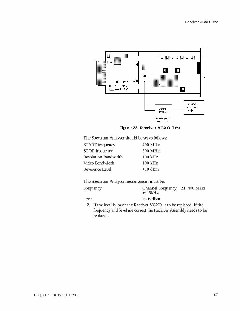
Figure 23 Receiver VCXO Test
The Spectrum Analyser should be set as follows:
START frequency 400 MHzSTOP frequency 500 MHzResolution Bandwidth 100 kHzVideo Bandwidth 100 kHzReverence Level +10 dBm
The Spectrum Analyser measurement must be:
Frequency Channel Frequency + 21 .400 MHz+/- 5kHz
Level > - 6 dBm2. If the level is lower the Receiver VCXO is to be replaced. If the
frequency and level are correct the Receiver Assembly needs to be replaced.
Chapter 8 - RF Bench Repair ��

Receiver VCXO Test
�� Chapter 8 - RF Bench Repair

%Theory of Operation
Transmitter Functional Blocks
US Gating
The US Gating circuitry generates the gated 1 MHz bursts for the US driver and the US receiver necessary in a pulsed doppler system.
The burst repetition rate is 3.2 kHz. The US driver burst has a duration of 96 µsec. The burst for the Receiver’s demodulator, which also has a duration of 96 µsec, follows the driver bursts with a delay of 32 µsec. This timing gives a sensitive depth range from 2.4cm up to 16.8cm (with a sound velocity in human tissue of 1500 m/sec.)
US Driver
The US Driver circuitry drives the ultrasound transducer crystals with the bursts delivered by the US Gating module. The output amplitude is 4V peak to peak. The drivers output goes to a high impedance state when the driving burst is inactive.
US Receiver
The US Receiver consists of three submodules:
• Preamplifier• Demodulator• Bandpass filter with amplification
The preamplifier amplifies the small doppler shifted 1MHz signals from the transducer. These are converted to the low frequency baseband by the
Chapter 9 - Theory of Operation �

Transmitter Functional Blocks
demodulator. This demodulator is driven by the US Gating module with 1 MHz bursts. The demodulated signals are amplified and bandpass filtered.
The overall gain from the transducer to the US Receiver’s output is 70 dB for the heartrate signal and 56 dB for the fetal movement signal.
ECG Driver
This circuitry powers an ECG transducer with a 5V peak to peak, 250 kHz square wave. The driver current is sensed by the ECG Receiver.
ECG Receiver
After converting into a voltage, the signal is amplified and bandpass filtered. The filter consists of a 15 Hz highpass and a 100 Hz lowpass. The overall gain from the transducer inputs to the ECG Receiver’s output is 56 dB. In addition, the ECG Receiver outputs an INOP flag if the 50/60 Hz signal or an INOP signal (250Hz delivered by the ECG transducer if electrodes have no contact) of a too high amplitude is detected.
Dynamic Compression Circuitry
The Dynamic Compression Circuitry consists of:
• Programmable Gain Amplifier (PGA)• Automatic Gain Control (AGC)
The PGA is a special amplifier with a programmable gain factor between 0 dB and 40 dB in 255 steps. It adapts the high dynamic range (>60 dB) of the heartrate signals to the limited dynamic range of the RF link. The PGA is controlled by the Automatic Gain Control.
The AGC circuitry sets the gain of the PGA to get the best usage of the RF link dynamic range. The actual heartrate singal amplitude is measured by a peak hold detector which is the input signal for the controller algorithm. The
algorithms for ECG and ultrasound signals are different. They are adapted to the special attributes of the signals. This results in different time constants, amplitude margins etc.
The gain is changed only between two signal complexes where the signal is approximately zero to avoid destruction of the signal complexes which may lead to an inaccurate calculated heartrate in the Fetal Monitor (artificial jitter).
FMP Detector
The FMP Detector consists of two parts:
• The FMP Envelope• The FMP Detector
The FMP Envelope circuitry builds the envelope signal of the fetal movement profile doppler signal from the US receiver. It is a full wave rectifier followed by a 12 Hz lowpass.
The Fetal Movement Profile Detector searches for fetal movement related signals in the FMP envelope signal. If a movement is detected, a status bit is
� Chapter 9 - Theory of Operation
Transmitter Functional Blocks
delivered to the FSK Generator. The detector algorithm is identical to the algorithm implemented in the Series 50 Fetal Monitors.
FMP is switched off whenever a Series 50 T Telemetry System (plugged into the Monitor) is switched on. FMP is switched back on again when the telemetry system is switched off (or unplugged). If you want to monitor FMP with a Series 50 T Telemetry System (and have the correct software revision and interface for Telemetry FMP) switch FMP on by using either the Key or the barcode method.
Modes
This module checks for connected transducers at the Cardio and Toco connectors. If a valid transducer is detected, the corresponding operating modes are set in the Transmitter (ECG/US, TOCO/IUP) and the mode encoding bits are delivered to the FSK signal generator. If an invalid transducer is detected, these bits are set to an error code and the Transmitter frontends are disabled.
Toco Driver
This circuitry drives a connected Toco or IUP transducer with a 1.6 kHz, 5V peak square wave. The 1.6 kHz frequency is synchronised with the 3.2 kHz repetition rate of the doppler ultrasound circuitries to avoid interference between the Toco and ultrasound channels.
Toco Receiver
This module contains a differential intput amplifier, a synchronous demodulator and a low pass filter, to derive a pressure proportional signal from the TOCO/IUP transducers bridge.
Toco A/D
The TOCO/IUP pressure signal is A to D converted by a sigma-delta type converter with a resolution of 12 bits and a 2Hz low pass characteristic. The repetition rate is 4/sec. These 12 bits are encoded in the serial bitstream by the FSK Generator module.
To ensure a high accuracy of the Toco pressure signal, correction factors are stored in a EEPROM during the production test individually for every Transmitter. Before encoding the Toco pressure values into the serial bitstream, the pressure values are corrected with these factors. This mechanism allows the usage of circuitries in the Toco frontends which only have stability over temperature and aging but not an absolute accuracy.
FSK Generator
The Frequency Shift Key generator (FSK), is a sine wave generator (smoothed square wave by filters) capable of generating either a frequency of 1.6 kHz (represents a logic zero) or 2.4 kHz (represents a logic one). It encodes the following signals in a bitstream:
• Coding pattern identification• Transmitters Serial Number• 12 Bit Toco pressure value
Chapter 9 - Theory of Operation ��

Transmitter Functional Blocks
• transducers and operating modes• fetal movement detection bit• battery status• external marker information• Nurse call button• INOP condition of ECG• CRC (checksum over one frame)• Special transmitter ID after power up (Japan only)
Oscillator
This circuitry produces the different clocks needed in the Transmitter. The oscillator is crystal controlled and starts operation at power supply voltages as low as 2V. This is necessary because the oscillator also drives the power supply. To ensure a start up over the complete specified battery voltage range, the oscillator must start at this low voltage. The clock freqencies are:
• 2 MHz for the mircocontroller• 1 MHz for the ultrasound drive/receive clocks and the power supply.• 500 kHz for the Toco sigma-delta A/D converter.• 250 kHz for the ECG driver and the Toco sigma-delta A/D converter.
Power Supply
The power supply is a switched mode power supply with step up operation. It works with a 250 kHz clock frequency (delivered by the oscillator) in a pulse width modulation mode. It is capable of delivering the necessary power in a fixed 5V output voltage for input voltages between 2.5V and 4.7V. (This covers the input voltages delivered by three AA type alkaline batteries or three AA type NiCd/NiHd accumulators).
Other supply voltages are derived from the 5V supply by linear regulators or by charge pumps runing at 250 kHz.
• 2.5V as virtual ground (linear regulator)• 8.5V for ultrasound preamplifier and OP-Amps (charge pump as
voltage doubler.) • -3.5V for OP-Amps (charge pumps as voltage inverter).
Service Interface
The service and production interface uses the marker input as the I/O connector for settings and internal status readings for service and production tests.
It is a RS232 similiar (0.5V only levels) serial interface with a specific protocol. This interface is used for:
• setting the Transmitter's serial number• reading some internal values for prodution tests• writing correction factors for the Toco frontend into the EEPROM.
�� Chapter 9 - Theory of Operation
Transmitter Functional Blocks
EEPROM
The EEPROM holds the following settings:
• Serial number• Gain calibration factors• Country code• Japanese ID code
Japan ID
This module is only acitve for Japanese options (set by the country code). It sends the required ID code for Japanese Telemetry Transmitters. If there is no valid ID code (or country code) in the EEPROM, this module shuts off the VCXO. RF emission is allowed only if a correct ID code is emitted first after power up.
VCXO
The Voltage Controlled Xtal (crystal) Oscillator is a "MAGIC" M1400-6XXXX type VCXO. It generates the 4mW, 2mW or 1mW RF carrier in the 406 to 470 MHz band. This is dependant on county options:
• 4 mW for USA and Australia• 2 mW for Europe• 1 mw for Japan
It also performs the FM modulation for this carrier with the composite signal of the ultasound doppler or the fetal scalp ECG and the FSK subcarrier for the digital information. The heart rate signals use 60% and the FSK subcarrier uses 40%of the available RF peak deviation. An additional lowpass filter at the VCXO's output reducers the RF carrier harmonics.
The outer shield of the heart rate transducer cables is used as an antenna. An impedence matching network adapts the antenna impedance to the VCXO's 50 Ohms output.
Chapter 9 - Theory of Operation ��

Receiver Functional Blocks
Receiver Functional Blocks
Input Filter
This module builds up a highpass filter with <1dB loss in the useful frequency range 406 to 470 MHz and >20dB rejection for 100 MHz signals. It prevents overloading of the RF preamplifier with strong lower frequency signals.
The filter also provides the preamplifier with a 21V DC power by coupling this DC voltage into the hot wire of the preamplifiers input cable. A capacitor decouples the DC power from the antenna input.
RF Preamp M1406A
This MAGIC line amplifier boosts the input signal by 12 dB. This results in an input sensitivity of about -118 dBm together with the M1402A RF Receiver. The amplifier is powered from the DC power at the hot wire of the input coax cable.
�� Chapter 9 - Theory of Operation
Receiver Functional Blocks
RF Receiver M1402A
The MAGIC receiver module M1402A performs the complete baseband signal recovery. The input signal is prefiltered, mixed down and filtered by a double superhetrodyne circuitry and demodulated to the baseband signal. An on board microcontroller does the complete automatic frequency control tracking of the input signal.
US Bandpass
This module performs a bandfiltering for the ultrasound doppler signal. It consists of a 60 Hz highpass to remove the low frequency noise of the FM demodulator, a 450 Hz lowpass to remove the higher frequency noise, and the FSK subcarrier. The subcarrier attenuation must be so high that it is not audible in the ultrasound signal (>70 dB at 1.6 kHz).
ECG Bandpass
This module performs a bandfiltering for the fetal scalp ECG signal with a 15 Hz highpass, to remove the low frequency noise (low frequency phase noise of the RF oscillators) and a 80 Hz lowpass, to remove the high frequency noise and the FSK subcarrier.
The output of the US or ECG bandpass is selected by the decoded mode information by the FSK Demodulator and fed to the receiver output as heartrate output. If the input signal quality is too bad (bit error rate increase over a certain limit), the heartrate and Toco output is switched off.
FSK Bandpass
This bandpass selects the FSK subcarrier out of the composite signal. It consists of a 1.6 KHz highpass to remove the low frequency noise and the heart rate signals, and a 2.4 kHz lowpass to eleminate the high frequency noise.
FSK Demodulator
The FSK Demodulator consists of:
• FSK Comperator• FSK Demodulator
The Comperator converts the sine shaped FSK subcarrier signal into a square wave. The Comperator has a hysteresis to improve the performance of noisy input signals. The Demodulator demodulates the FSK subcarrier and recovers the encoded bitstream. The synchronisation is done by searching the encoded 12 bit serial number. The bitstream is also descrambled and the CRC is checked. If the test is positive, the complete frame is saved and the information bits are recovered and appropriate actions are taken:
• Set the Mode outputs• Display the status values on the front panel.• Switch On/Off the nurse call beeper• Switch On all output signals• Set the fetal movement output
Chapter 9 - Theory of Operation ��
Receiver Functional Blocks
• Encode the marker signal into the Toco signal
If more than two consecutive frames are disturbed (wrong CRC checksum) or no synchonisation is possible due to not matching serial numbers of the transmitter and the receiver, the output signals are switched off and the range/transmission INOP LED on the frontpanel is switched on.
Toco D/A Converter
This module converts the digital Toco value (12 bits) into an analog voltage (the fetal monitors can only accept analog input signals for all parameters). It is built up with a pulse width modulator followed by a 3Hz lowpass.
The marker is also encoded with the Toco output signal. If a marker pressed bit is received, the Toco signal will make a deflection over the complete range for 1 second if a fetal monitor with an old telemetry interface is connected. If a new interface is detected, the marker will be output as a digital mode output only.
EEPROM
The EEPROM keeps the following settings:
• Serial Number• Nurse Call volume control
These values all can be set via the Service/Production interface, or in the case of the nurse call volume control, by pressing the nurse call acknowledge button if no nurse call is active.
Service Interface
This is a RS232 type serial interface used for servicing and production test and settings, to read back internal values or to store serial numbers and other settings in the EEPROM.
Power Supply
This module delivers all the necessary supply voltages. It has an input selector for 110V or 230V mains input. It outputs the following voltages:
+21V RF Preamplifier+12V Analog circuitries and the M1402A Receiver Module-12V Analog circuitries and the M1402A Receiver Module+5V Digital circuitries and the M1402A Receiver Module
Oscillator
The oscillator produces a CMOS clock signal for the digital circuitries. It is running at 16.256 MHz. This frequency is divided by 2; the resulting 8.128 MHz frequency is used as a clock signal for the microcontroller.
�� Chapter 9 - Theory of Operation
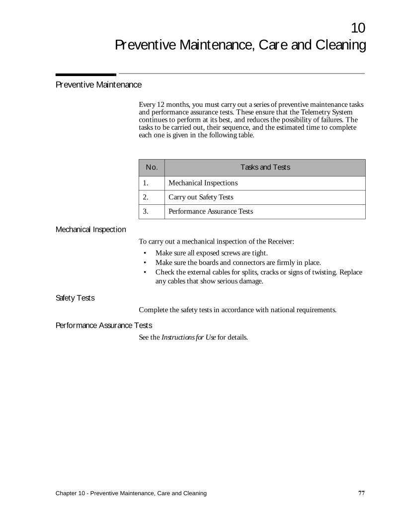
10Preventive Maintenance, Care and Cleaning
Preventive Maintenance
Every 12 months, you must carry out a series of preventive maintenance tasks and performance assurance tests. These ensure that the Telemetry System continues to perform at its best, and reduces the possibility of failures. The tasks to be carried out, their sequence, and the estimated time to complete each one is given in the following table.
Mechanical Inspection
To carry out a mechanical inspection of the Receiver:
• Make sure all exposed screws are tight.• Make sure the boards and connectors are firmly in place.• Check the external cables for splits, cracks or signs of twisting. Replace
any cables that show serious damage.
Safety Tests
Complete the safety tests in accordance with national requirements.
Performance Assurance Tests
See the Instructions for Use for details.
No. Tasks and Tests
1. Mechanical Inspections
2. Carry out Safety Tests
3. Performance Assurance Tests
Chapter 10 - Preventive Maintenance, Care and Cleaning ��

Care and Cleaning of the Telemetry System
Care and Cleaning of the Telemetry System
For care and cleaning instructions, please refer to the Instructions for Use.
�� Chapter 10 - Preventive Maintenance, Care and Cleaning

11Channels and Frequencies
VCXO Operation Frequency
The Receiver VCXO operation frequency equals the channel frequency plus 21.4 MHz.
Austria
Australia
M1310A Option
Ref M1402A Channel Frequency (MHz)
Transmitter VCXO-P/N
Receiver VCXO-PN
J01 801 449.775 M1400-61801 M1402-61801
J02 802 449.800 M1400-61802 M1402-61802
J03 803 449.850 M1400-61803 M1402-61803
J04 804 449.825 M1400-61804 M1402-61804
M1310A Option
Ref M1402A Channel Frequency (MHz)
Transmitter VCXO-P/N
Receiver VCXO-PN
A10 510 469.500 M1400-61510 M1402-61510
A11 511 469.525 M1400-61511 M1402-61511
A12 512 469.550 M1400-61512 M1402-61512
A13 513 469.575 M1400-61513 M1402-61513
A14 514 469.600 M1400-61514 M1402-61514
A15 515 469.625 M1400-61515 M1402-61515
A16 516 469.650 M1400-61516 M1402-61516
A17 517 469.675 M1400-61517 M1402-61517
A18 518 469.700 M1400-61518 M1402-61518
A19 519 469.725 M1400-61519 M1402-61519
Chapter 11 - Channels and Frequencies �

Belgium
Belgium
Canada
M1310A Option
Ref M1402A Channel Frequency (MHz)
Transmitter VCXO-P/N
Receiver VCXO-PN
001 001 467.775 M1400-61001 M1402-61001
002 555 470.025 M1400-61555 M1402-61555
003 556 470.050 M1400-61556 M1402-61556
005 557 470.075 M1400-61557 M1402-61557
006 558 470.100 M1400-61558 M1402-61558
391 391 457.525 M1400-61391 M1402-61391
392 392 457.600 M1400-61392 M1402-61392
393 393 466.2375 M1400-61393 M1402-61393
D05 605 448.250 M1400-61605 M1402-61605
D06 606 448.275 M1400-61606 M1402-61606
D08 608 448.125 M1400-61608 M1402-61608
D09 609 448.150 M1400-61609 M1402-61609
D10 610 448.175 M1400-61610 M1402-61610
D11 611 448.200 M1400-61611 M1402-61611
D12 612 448.225 M1400-61612 M1402-61612
M1310A Option
Ref M1402A Channel Frequency (MHz)
Transmitter VCXO-P/N
Receiver VCXO-PN
J01 801 449.775 M1400-61801 M1402-61801
J02 802 449.800 M1400-61802 M1402-61802
J03 803 449.850 M1400-61803 M1402-61803
L01 701 458.500 M1400-61701 M1402-61701
L02 702 458.525 M1400-61702 M1402-61702
L03 703 458.5625 M1400-61703 M1402-61703
� Chapter 11 - Channels and Frequencies
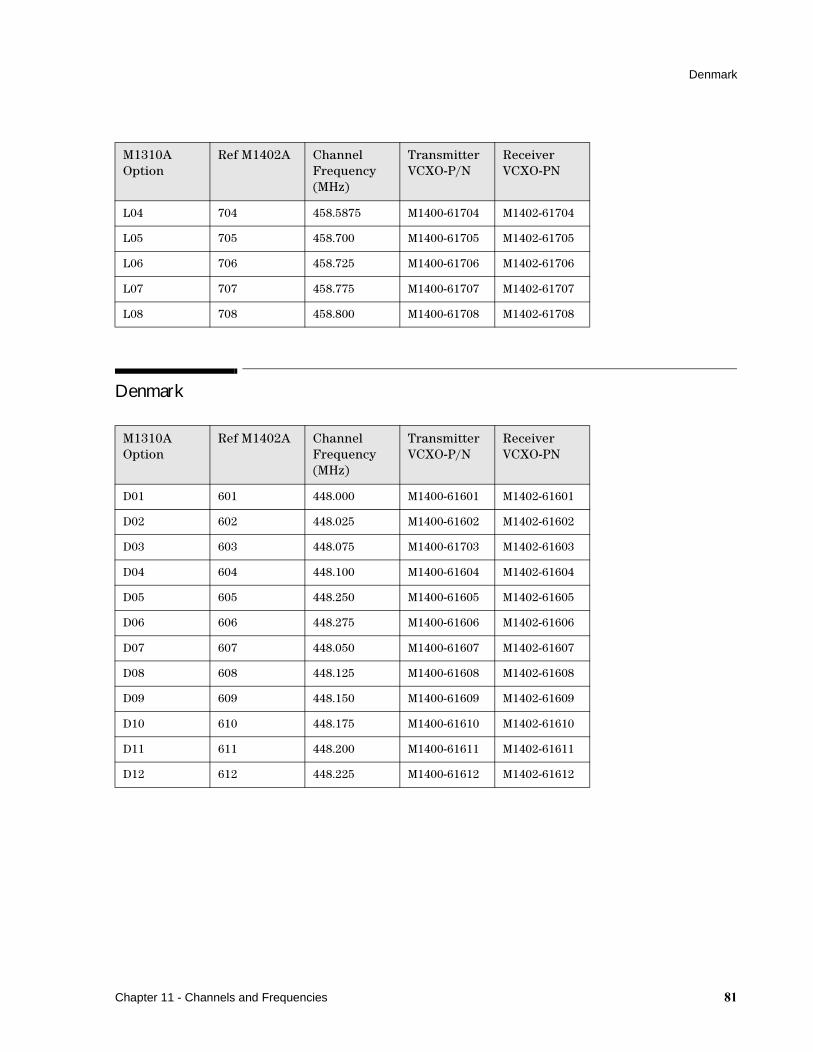
Denmark
Denmark
L04 704 458.5875 M1400-61704 M1402-61704
L05 705 458.700 M1400-61705 M1402-61705
L06 706 458.725 M1400-61706 M1402-61706
L07 707 458.775 M1400-61707 M1402-61707
L08 708 458.800 M1400-61708 M1402-61708
M1310A Option
Ref M1402A Channel Frequency (MHz)
Transmitter VCXO-P/N
Receiver VCXO-PN
D01 601 448.000 M1400-61601 M1402-61601
D02 602 448.025 M1400-61602 M1402-61602
D03 603 448.075 M1400-61703 M1402-61603
D04 604 448.100 M1400-61604 M1402-61604
D05 605 448.250 M1400-61605 M1402-61605
D06 606 448.275 M1400-61606 M1402-61606
D07 607 448.050 M1400-61607 M1402-61607
D08 608 448.125 M1400-61608 M1402-61608
D09 609 448.150 M1400-61609 M1402-61609
D10 610 448.175 M1400-61610 M1402-61610
D11 611 448.200 M1400-61611 M1402-61611
D12 612 448.225 M1400-61612 M1402-61612
M1310A Option
Ref M1402A Channel Frequency (MHz)
Transmitter VCXO-P/N
Receiver VCXO-PN
Chapter 11 - Channels and Frequencies ��
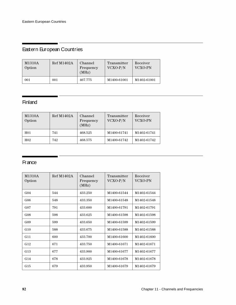
Eastern European Countries
Eastern European Countries
Finland
France
M1310A Option
Ref M1402A Channel Frequency (MHz)
Transmitter VCXO-P/N
Receiver VCXO-PN
001 001 467.775 M1400-61001 M1402-61001
M1310A Option
Ref M1402A Channel Frequency (MHz)
Transmitter VCXO-P/N
Receiver VCXO-PN
H01 741 468.525 M1400-61741 M1402-61741
H02 742 468.575 M1400-61742 M1402-61742
M1310A Option
Ref M1402A Channel Frequency (MHz)
Transmitter VCXO-P/N
Receiver VCXO-PN
G04 544 433.250 M1400-61544 M1402-61544
G06 548 433.350 M1400-61548 M1402-61548
G07 791 433.600 M1400-61791 M1402-61791
G08 598 433.625 M1400-61598 M1402-61598
G09 599 433.650 M1400-61599 M1402-61599
G10 588 433.675 M1400-61588 M1402-61588
G11 600 433.700 M1400-61600 M1402-61600
G12 671 433.750 M1400-61671 M1402-61671
G13 677 433.900 M1400-61677 M1402-61677
G14 678 433.925 M1400-61678 M1402-61678
G15 679 433.950 M1400-61679 M1402-61679
�� Chapter 11 - Channels and Frequencies
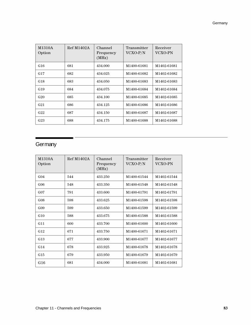
Germany
Germany
G16 681 434.000 M1400-61681 M1402-61681
G17 682 434.025 M1400-61682 M1402-61682
G18 683 434.050 M1400-61683 M1402-61683
G19 684 434.075 M1400-61684 M1402-61684
G20 685 434.100 M1400-61685 M1402-61685
G21 686 434.125 M1400-61686 M1402-61686
G22 687 434.150 M1400-61687 M1402-61687
G23 688 434.175 M1400-61688 M1402-61688
M1310A Option
Ref M1402A Channel Frequency (MHz)
Transmitter VCXO-P/N
Receiver VCXO-PN
G04 544 433.250 M1400-61544 M1402-61544
G06 548 433.350 M1400-61548 M1402-61548
G07 791 433.600 M1400-61791 M1402-61791
G08 598 433.625 M1400-61598 M1402-61598
G09 599 433.650 M1400-61599 M1402-61599
G10 588 433.675 M1400-61588 M1402-61588
G11 600 433.700 M1400-61600 M1402-61600
G12 671 433.750 M1400-61671 M1402-61671
G13 677 433.900 M1400-61677 M1402-61677
G14 678 433.925 M1400-61678 M1402-61678
G15 679 433.950 M1400-61679 M1402-61679
G16 681 434.000 M1400-61681 M1402-61681
M1310A Option
Ref M1402A Channel Frequency (MHz)
Transmitter VCXO-P/N
Receiver VCXO-PN
Chapter 11 - Channels and Frequencies ��
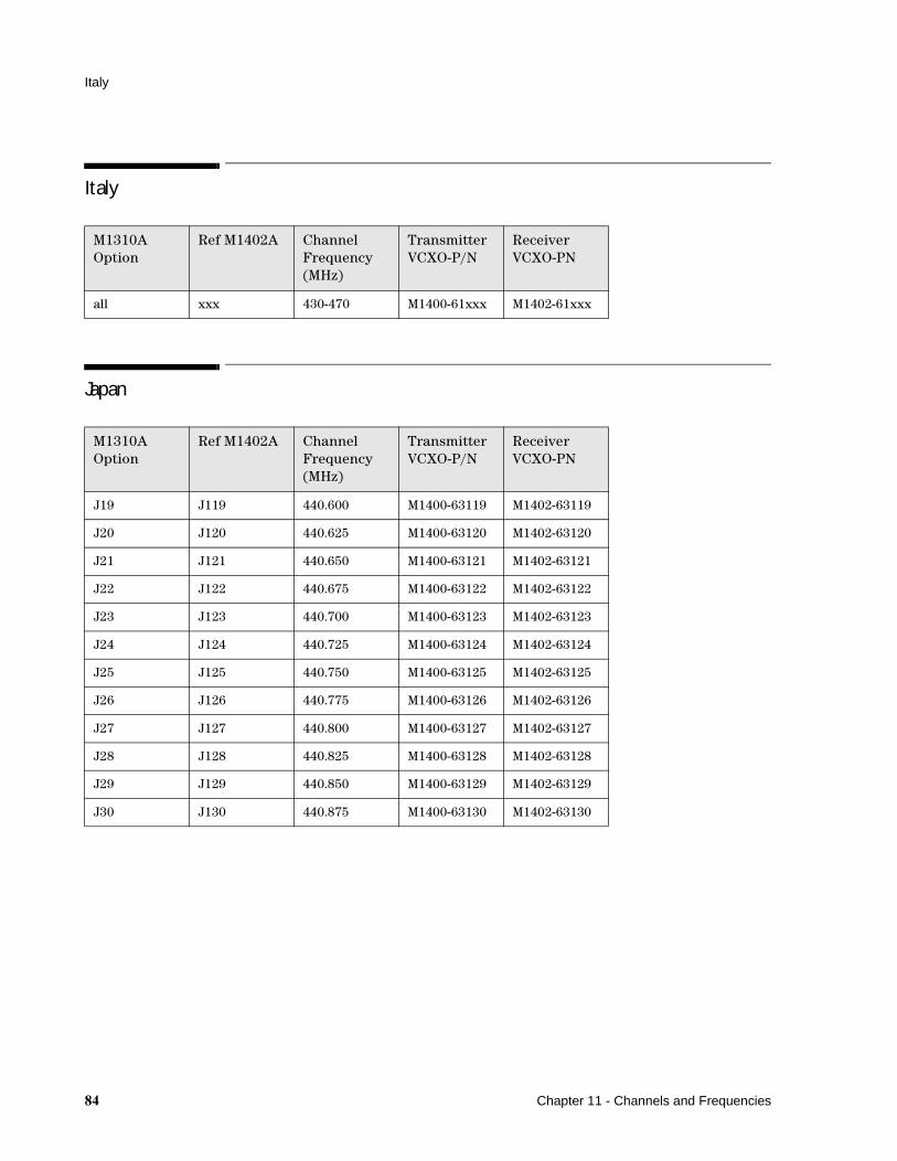
Italy
Italy
Japan
M1310A Option
Ref M1402A Channel Frequency (MHz)
Transmitter VCXO-P/N
Receiver VCXO-PN
all xxx 430-470 M1400-61xxx M1402-61xxx
M1310A Option
Ref M1402A Channel Frequency (MHz)
Transmitter VCXO-P/N
Receiver VCXO-PN
J19 J119 440.600 M1400-63119 M1402-63119
J20 J120 440.625 M1400-63120 M1402-63120
J21 J121 440.650 M1400-63121 M1402-63121
J22 J122 440.675 M1400-63122 M1402-63122
J23 J123 440.700 M1400-63123 M1402-63123
J24 J124 440.725 M1400-63124 M1402-63124
J25 J125 440.750 M1400-63125 M1402-63125
J26 J126 440.775 M1400-63126 M1402-63126
J27 J127 440.800 M1400-63127 M1402-63127
J28 J128 440.825 M1400-63128 M1402-63128
J29 J129 440.850 M1400-63129 M1402-63129
J30 J130 440.875 M1400-63130 M1402-63130
�� Chapter 11 - Channels and Frequencies
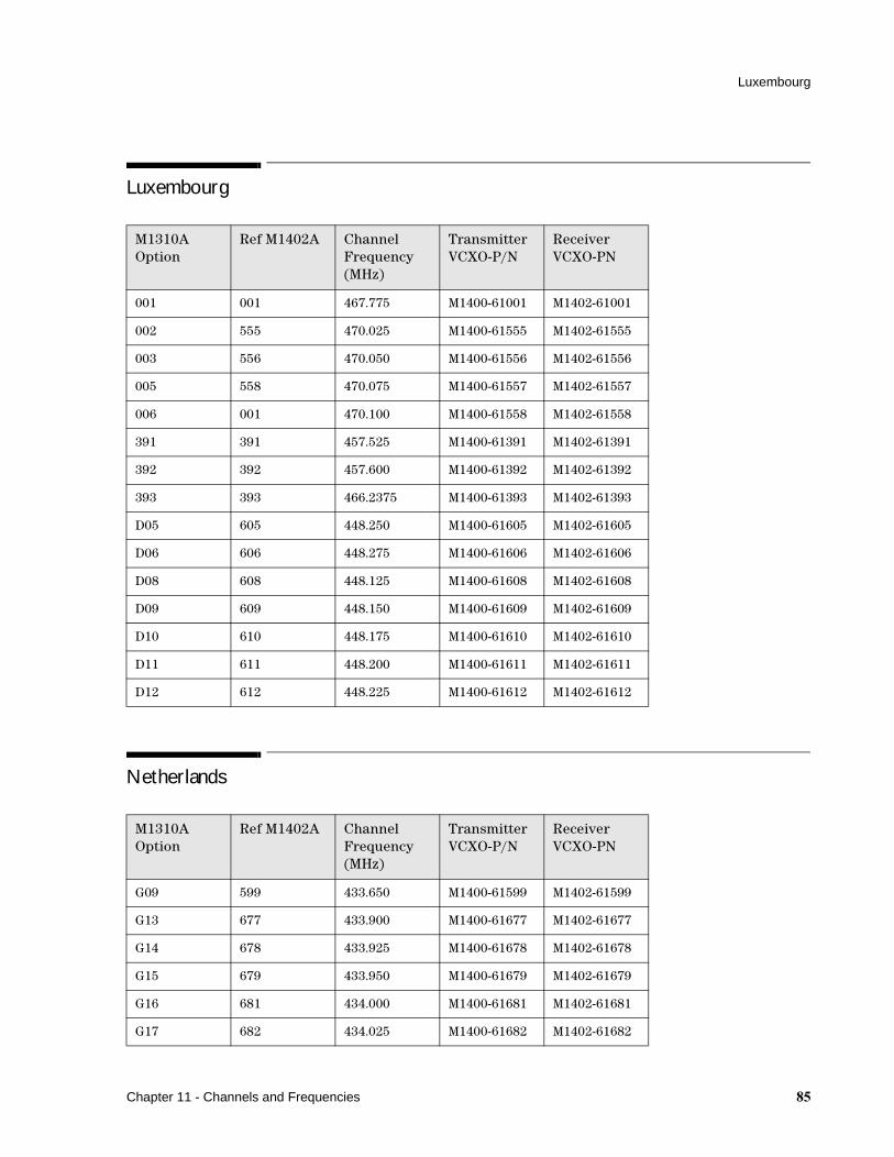
Luxembourg
Luxembourg
Netherlands
M1310A Option
Ref M1402A Channel Frequency (MHz)
Transmitter VCXO-P/N
Receiver VCXO-PN
001 001 467.775 M1400-61001 M1402-61001
002 555 470.025 M1400-61555 M1402-61555
003 556 470.050 M1400-61556 M1402-61556
005 558 470.075 M1400-61557 M1402-61557
006 001 470.100 M1400-61558 M1402-61558
391 391 457.525 M1400-61391 M1402-61391
392 392 457.600 M1400-61392 M1402-61392
393 393 466.2375 M1400-61393 M1402-61393
D05 605 448.250 M1400-61605 M1402-61605
D06 606 448.275 M1400-61606 M1402-61606
D08 608 448.125 M1400-61608 M1402-61608
D09 609 448.150 M1400-61609 M1402-61609
D10 610 448.175 M1400-61610 M1402-61610
D11 611 448.200 M1400-61611 M1402-61611
D12 612 448.225 M1400-61612 M1402-61612
M1310A Option
Ref M1402A Channel Frequency (MHz)
Transmitter VCXO-P/N
Receiver VCXO-PN
G09 599 433.650 M1400-61599 M1402-61599
G13 677 433.900 M1400-61677 M1402-61677
G14 678 433.925 M1400-61678 M1402-61678
G15 679 433.950 M1400-61679 M1402-61679
G16 681 434.000 M1400-61681 M1402-61681
G17 682 434.025 M1400-61682 M1402-61682
Chapter 11 - Channels and Frequencies ��
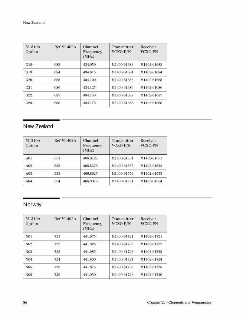
New Zealand
New Zealand
Norway
G18 683 434.050 M1400-61683 M1402-61683
G19 684 434.075 M1400-61684 M1402-61684
G20 685 434.100 M1400-61685 M1402-61685
G21 686 434.125 M1400-61686 M1402-61686
G22 687 434.150 M1400-61687 M1402-61687
G23 688 434.175 M1400-61688 M1402-61688
M1310A Option
Ref M1402A Channel Frequency (MHz)
Transmitter VCXO-P/N
Receiver VCXO-PN
A01 551 466.8125 M1400-61551 M1402-61551
A02 552 466.8375 M1400-61552 M1402-61552
A03 553 466.8625 M1400-61553 M1402-61553
A04 554 466.8875 M1400-61554 M1402-61554
M1310A Option
Ref M1402A Channel Frequency (MHz)
Transmitter VCXO-P/N
Receiver VCXO-PN
N01 721 441.975 M1400-61721 M1402-61721
N02 722 441.925 M1400-61722 M1402-61722
N03 723 441.985 M1400-61723 M1402-61723
N04 724 441.900 M1400-61724 M1402-61724
N05 725 441.875 M1400-61725 M1402-61725
N06 726 441.950 M1400-61726 M1402-61726
M1310A Option
Ref M1402A Channel Frequency (MHz)
Transmitter VCXO-P/N
Receiver VCXO-PN
�� Chapter 11 - Channels and Frequencies
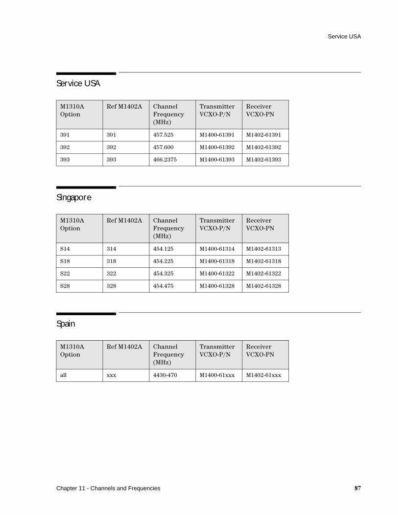
Service USA
Service USA
Singapore
Spain
M1310A Option
Ref M1402A Channel Frequency (MHz)
Transmitter VCXO-P/N
Receiver VCXO-PN
391 391 457.525 M1400-61391 M1402-61391
392 392 457.600 M1400-61392 M1402-61392
393 393 466.2375 M1400-61393 M1402-61393
M1310A Option
Ref M1402A Channel Frequency (MHz)
Transmitter VCXO-P/N
Receiver VCXO-PN
S14 314 454.125 M1400-61314 M1402-61313
S18 318 454.225 M1400-61318 M1402-61318
S22 322 454.325 M1400-61322 M1402-61322
S28 328 454.475 M1400-61328 M1402-61328
M1310A Option
Ref M1402A Channel Frequency (MHz)
Transmitter VCXO-P/N
Receiver VCXO-PN
all xxx 4430-470 M1400-61xxx M1402-61xxx
Chapter 11 - Channels and Frequencies ��
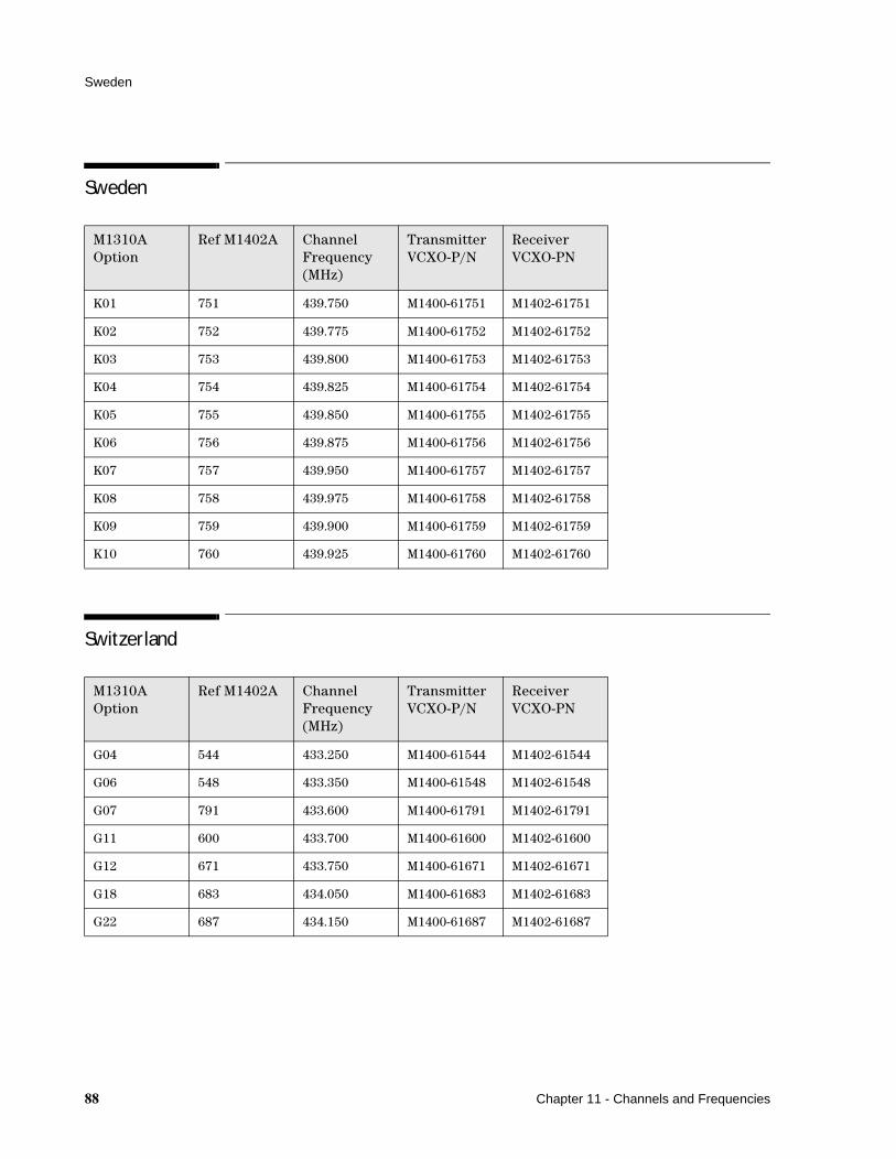
Sweden
Sweden
Switzerland
M1310A Option
Ref M1402A Channel Frequency (MHz)
Transmitter VCXO-P/N
Receiver VCXO-PN
K01 751 439.750 M1400-61751 M1402-61751
K02 752 439.775 M1400-61752 M1402-61752
K03 753 439.800 M1400-61753 M1402-61753
K04 754 439.825 M1400-61754 M1402-61754
K05 755 439.850 M1400-61755 M1402-61755
K06 756 439.875 M1400-61756 M1402-61756
K07 757 439.950 M1400-61757 M1402-61757
K08 758 439.975 M1400-61758 M1402-61758
K09 759 439.900 M1400-61759 M1402-61759
K10 760 439.925 M1400-61760 M1402-61760
M1310A Option
Ref M1402A Channel Frequency (MHz)
Transmitter VCXO-P/N
Receiver VCXO-PN
G04 544 433.250 M1400-61544 M1402-61544
G06 548 433.350 M1400-61548 M1402-61548
G07 791 433.600 M1400-61791 M1402-61791
G11 600 433.700 M1400-61600 M1402-61600
G12 671 433.750 M1400-61671 M1402-61671
G18 683 434.050 M1400-61683 M1402-61683
G22 687 434.150 M1400-61687 M1402-61687
�� Chapter 11 - Channels and Frequencies
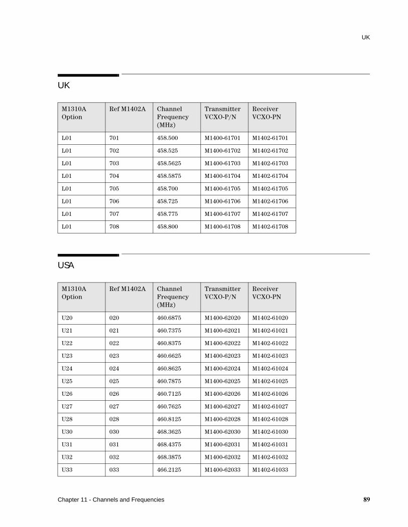
UK
UK
USA
M1310A Option
Ref M1402A Channel Frequency (MHz)
Transmitter VCXO-P/N
Receiver VCXO-PN
L01 701 458.500 M1400-61701 M1402-61701
L01 702 458.525 M1400-61702 M1402-61702
L01 703 458.5625 M1400-61703 M1402-61703
L01 704 458.5875 M1400-61704 M1402-61704
L01 705 458.700 M1400-61705 M1402-61705
L01 706 458.725 M1400-61706 M1402-61706
L01 707 458.775 M1400-61707 M1402-61707
L01 708 458.800 M1400-61708 M1402-61708
M1310A Option
Ref M1402A Channel Frequency (MHz)
Transmitter VCXO-P/N
Receiver VCXO-PN
U20 020 460.6875 M1400-62020 M1402-61020
U21 021 460.7375 M1400-62021 M1402-61021
U22 022 460.8375 M1400-62022 M1402-61022
U23 023 460.6625 M1400-62023 M1402-61023
U24 024 460.8625 M1400-62024 M1402-61024
U25 025 460.7875 M1400-62025 M1402-61025
U26 026 460.7125 M1400-62026 M1402-61026
U27 027 460.7625 M1400-62027 M1402-61027
U28 028 460.8125 M1400-62028 M1402-61028
U30 030 468.3625 M1400-62030 M1402-61030
U31 031 468.4375 M1400-62031 M1402-61031
U32 032 468.3875 M1400-62032 M1402-61032
U33 033 466.2125 M1400-62033 M1402-61033
Chapter 11 - Channels and Frequencies �

USA
U34 034 466.2625 M1400-62034 M1402-61034
U35 035 466.3375 M1400-62035 M1402-61035
U36 036 466.2875 M1400-62036 M1402-61036
U37 037 468.7625 M1400-62037 M1402-61037
U38 038 468.8125 M1400-62038 M1402-61038
U39 039 468.8875 M1400-62039 M1402-61039
U40 040 468.8375 M1400-62040 M1402-61040
U41 041 469.0875 M1400-62041 M1402-61041
U42 042 469.1375 M1400-62042 M1402-61042
U43 043 469.2125 M1400-62043 M1402-61043
U44 044 469.1625 M1400-62044 M1402-61044
U45 045 466.6625 M1400-62045 M1402-61045
U46 046 466.7125 M1400-62046 M1402-61046
U47 047 466.7875 M1400-62047 M1402-61047
U48 048 466.7375 M1400-62048 M1402-61048
U49 049 468.2875 M1400-62049 M1402-61049
U50 050 468.3375 M1400-62050 M1402-61050
U87 087 466.4125 M1400-62087 M1402-61087
U88 088 466.4875 M1400-62088 M1402-61088
U89 089 466.5625 M1400-62089 M1402-61089
U90 090 466.8375 M1400-62090 M1402-61090
U91 091 466.9125 M1400-62091 M1402-61091
U92 092 466.5875 M1400-62092 M1402-61092
U93 093 466.9875 M1400-62093 M1402-61093
U94 094 466.8625 M1400-62094 M1402-61094
U95 095 466.6125 M1400-62095 M1402-61095
U96 096 466.9375 M1400-62096 M1402-61096
391 391 457.525 M1400-61391 M1402-61391
392 392 457.600 M1400-61392 M1402-61392
M1310A Option
Ref M1402A Channel Frequency (MHz)
Transmitter VCXO-P/N
Receiver VCXO-PN
Chapter 11 - Channels and Frequencies

USA
393 393 466.2375 M1400-61393 M1402-61393
M1310A Option
Ref M1402A Channel Frequency (MHz)
Transmitter VCXO-P/N
Receiver VCXO-PN
Chapter 11 - Channels and Frequencies �

USA
� Chapter 11 - Channels and Frequencies

��&��
B
batterieslow warning light, 18operating time, 17
bench repairRF, 59, 69, 77, 79
bench testReceiver assembly, 65Receiver preamplifier, 64Receiver VCXO, 66Transmitter VCXO, 60
C
cables, 8remote event marker, 10service cable assembly, 33transducer, 8
Channel Frequency, 79Frequency option
numbers, 79
D
DECG transducers, 9display board
replacement and removal, 57Dynamic Compression
Circuitry, 70
E
ECG Bandpass, 75ECG Driver, 70ECG Receiver, 70EEPROM
Receiver functional blocks, 74transmitter, 73
environment, 2specifications, 5
error flowchartcardio channel, 25event marker, 29FMP, 27
no LED’s lit on receiver, 19not all LED's lit, 21nurse call, 30Toco channel, 26transducer not detected, 24transmission INOP range, 22transmission range, 23yellow LED stays on, 21
error messages, 14
F
fetal monitor interfacepin connections, 31
FMP Detector, 70FSK Bandpass, 75FSK Demodulator, 75FSK Generator, 71fuse
part numbers, 44replacement and removal, 58values, 58
I
Input Filter, 74interface
pin connections, 31to fetal monitor, 31
IUP transducerspecifications, 10
J
Japan ID, 73
M
maximum input/output voltages, 4
Modes, 71
O
operatingenvironment, 2temperatures, 2
OscillatorReceiver, 76Transmitter, 72
P
parameter test, 13parts
ordering, 39replacing, 39
parts listReceiver Boards, 42Receiver Parts, 42transducers, 45Transmitter, 40
patient safety, 2pin connections
fetal monitor interface, 31power supply
Receiver, 76replacement and removal, 53Transmitter, 72
preventive maintenance, 77problem solving, 17problems
solving general, 17processor board
replacement and removal, 54protective earth, 3
R
Receiverassembly bench test, 65VCXO bench test, 66VCXO replacement and
removal, 56receiver
preamplifier bench test, 64testing, 11
Index �
Receiver functional blocksECG Bandpass, 74EEPROM, 74FSK Bandpass, 74FSK Demodulator, 74Input Filter, 74Oscillator, 74power supply, 74RF Preamp M1406A, 74RF Receiver M1402A, 74service interface, 74Toco D/A Converter, 74US Bandpass, 74
Receiver VCXO Test, 67remote event marker
cables, 10specifications, 10
replacement and removal, 39display board, 57fuses, 58power supply board, 53processor board, 54Receiver VCXO, 56RF amplifier, 57RF Module, 55Transmitter, 46Transmitter processor
board, 47Transmitter VCXO, 48, 50
RFamplifier replacement and
removal, 57bench repair, 59, 69, 77, 79bench test, 59Module replacement and
removal, 55Preamp M1406A, 74Receiver M1402A, 75
S
safety, 1self test, 7
receiver, 11
�
transmitter, 12service interface, 76service program, 33
cable assembly, 33check receiver, 36check transmitter, 36exit, 37power on self test, 36read country information, 37read serial number/
revisions, 36reset serial number, 37serial number to receiver, 36serial number to
transmitter, 36show last error/warning, 36using, 34
specificationsantenna, 6channels & frequencies, 6DECG transducers, 9environment, 5inputs, 6IUP transducer, 10power requirements, 5remote event marker, 10Telemetry, 5Toco transducer, 8
storagetemperatures, 2
T
testing, 7parameter test, 13Receiver assembly, 65Receiver preamplifier, 64receiver self test, 11Receiver VCXO, 66RF bench test, 59self test, 7transmitter self test, 12Transmitter VCXO, 60
theory of operation, 69
Dynamic Compression Circuitry, 70
ECG Bandpass, 75ECG Driver, 70ECG Receiver, 70EEPROM transmitter, 73EEPROM, Receiver, 76FMP Detector, 70FSK Bandpass, 75FSK Demodulator, 75FSK Generator, 71Input filter, 74Japan ID, 73Modes, 71Oscillator Receiver functional
blocks, 76Oscillator transmitter, 72power supply transmitter, 72power supply, Receiver, 76RF Preamp M1406A, 74RF Receiver M1402A, 75service interface, 76service interface
transmitter, 72Toco A/D, 71Toco D/A Converter, 76Toco Driver, 71Toco Receiver, 71Transmitter, 69US Bandpass, 75US Driver, 69US Gating, 69US Receiver, 69VCXO, Transmitter, 73
TocoA/D, 71D/A Converter, 76Driver, 71Receiver, 71transducer, 8
transducers, 8cables, 8DECG, 9IUP, 10Toco, 8
Index

ultrasound, 8watertight blue, 2
Transmitterreplacement and removal, 50
transmittertesting, 12
Transmitter functional blocksDynamic Compression
Circuitry, 69ECG Driver, 69ECG Receiver, 69EEPROM, 69FMP Detector, 69FSK Generator, 69Japan ID, 69Modes, 69Oscillator, 69power supply, 69service interface, 69Toco A/D, 69Toco Driver, 69
Toco Receiver, 69US Driver, 69US Gating, 69US Receiver, 69VCXO, 69
Transmitter processor boardreplacement and removal, 47
Transmitter VCXObench test, 60replacement and removal, 50
troubleshooting, 17general problems, 17
troubleshooting flowchartcardio channel, 25event marker, 29FMP, 27no LED’s lit on receiver, 19not all LED's lit, 21nurse call, 30Toco channel, 26transducer not detected, 24transmission INOP range, 22
transmission range, 23yellow LED stays on, 21
U
ultrasound transducer, 8US Bandpass, 75US Gating, 69US Receiver, 69
V
VCXOReceiver bench test, 67Transmitter, 73Transmitter bench test, 60
voltagefuse values, 58output power, 7power requirements, 5power supply board, 53
Index �


