IM14229-R04 (3835192-B) SENTRONIC PLUS Digital Pressure Regulator Series 614 Régulateur de pression numérique Series 614 Digitaler Druckregler Baureihe 614 Installation manual Manuel d'installation Installationshandbuch GB FR DE
Transcript
IM14229-R04(3835192-B)
SentronicPLUS
Digital Pressure RegulatorSeries 614
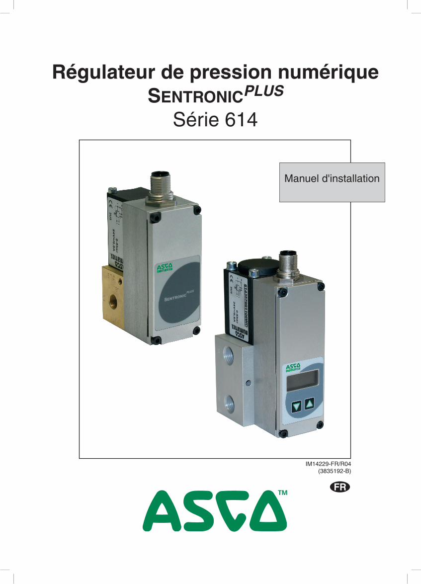
Régulateur de pression numériqueSeries 614
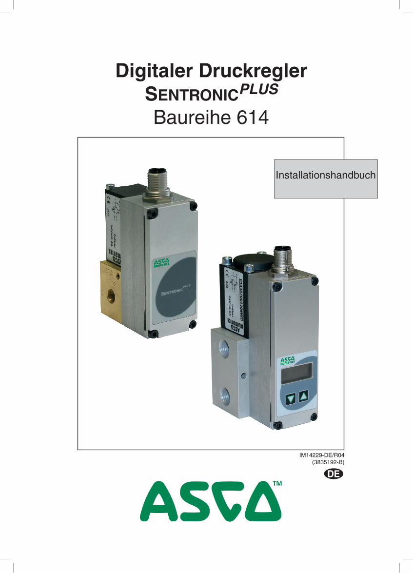
Digitaler DruckreglerBaureihe 614
Installation manualManuel d'installation
Installationshandbuch
GB FR DE
GB
FR
DE
SUMMARYSOMMAIRE
INHALT
English version _______________________________________________________ 2
7. Maintenance and care .........................................................................................................................................10
8. Dimensions and weight .......................................................................................................................................11
Version française _____________________________________________________ 19
Deutsche Version _____________________________________________________ 29
CAUTION! Dangerous operating conditions may occur when using the programming interface on the valve as the valve may possibly not react to the analog setpoint any more.Provide for protection against uncontrolled movement of equipment when putting the valve into operation and before making any modifications to the valve settings.
NOTICEThe information in this manual is subject to change without notice.In no event shall ASCO NUMATICS be liable for technical or editorial errors or omissions. Neither is any liability assumed for accidental or consequential damages arising out of or in connection with the supply or use of the information contained herein.THIS MANUAL CONTAINS INFORMATION PROTECTED BY COPYRIGHT. NO PART OF THIS DOCUMENT MAY BE PHOTOCOPIED OR REPRODUCED IN ANY FORM OR MANNER WHATSOEVER WITHOUT PRIOR WRITTEN PERMISSION FROM ASCO NUMATICS.
This product complies with the essential requirements of the EMC Directive 2014/30/EU and its amendments. It is CE-approved. A separate Declaration of Conformity is available on request.Please provide ordering code and serial numbers of products concerned.
We herewith declare that the version of the product described in this installation manual is intended to be incorporated into or assembled with other machinery and that it must not be put into service until the machinery into which it is to be incorporated has been declared in conformity with the provisions of Council Directive 2006/42/EC.Handling, assembly and putting into service and all settings and adjustments must be done by qualified, authorised personnel only.
This product contains electronic components sensitive to electrostatic discharge. An electrostatic discharge generated by a person or object coming in contact with the electrical components can damage or destroy the product.To avoid the risk of electrostatic discharge, please observe the handling precautions and recommendations contained in standard EN 100015-1. Do not connect or disconnect the device while it is energised.
C A U T I O NOBSERVE PRECAUTIONS
FOR HANDLINGELECTROSTATIC SENSITIVE
DEVICES
!
INSTALLATION
IM14229-3
GB
B: Control panelD = M12 with display - non-explosionproofE = M12 without display - explosionproof (ATEX)F = DIN connector, 7-pin, with display - non-explosionproofG = DIN connector, 7-pin without display - non-explosionproof
A: VERSION (ports), body0 = DN6 (G 1/4), Alu 6 = DN20 (NPT 1"), Alu1 = DN12 (G 1/2), Alu 7 = DN3 (G 1/8), Ms2 = DN20 (G 1), Alu 8 = DN6 (G 1/4), Ms3 = DN6 (ISO 1), Alu 9 = DN3 (NPT 1/8), Ms4 = DN6 (NPT 1/4"), Alu A = DN6 (NPT 1/4"), Ms5 = DN12 (NPT 1/2"), Alu C = DN6 (G 1/4), VA H = DN6 (G 1/4), Ms2)
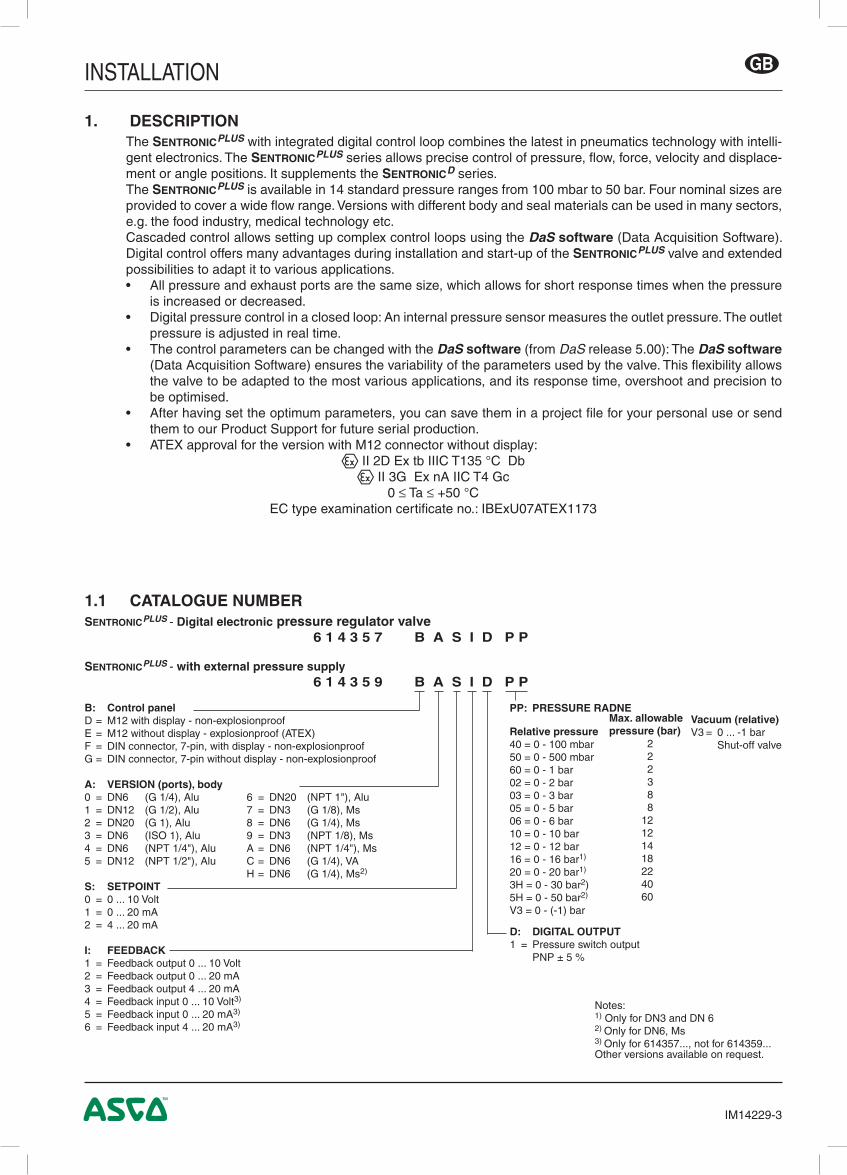
1. DESCRIPTIONThe SentronicPLUS with integrated digital control loop combines the latest in pneumatics technology with intelli-gent electronics. The SentronicPLUS series allows precise control of pressure, flow, force, velocity and displace-ment or angle positions. It supplements the SentronicD series.The SentronicPLUS is available in 14 standard pressure ranges from 100 mbar to 50 bar. Four nominal sizes are provided to cover a wide flow range. Versions with different body and seal materials can be used in many sectors, e.g. the food industry, medical technology etc.Cascaded control allows setting up complex control loops using the DaS software (Data Acquisition Software). Digital control offers many advantages during installation and start-up of the SentronicPLUS valve and extended possibilities to adapt it to various applications.• All pressure and exhaust ports are the same size, which allows for short response times when the pressure
is increased or decreased.• Digital pressure control in a closed loop: An internal pressure sensor measures the outlet pressure. The outlet
pressure is adjusted in real time.• The control parameters can be changed with the DaS software (from DaS release 5.00): The DaS software
(Data Acquisition Software) ensures the variability of the parameters used by the valve. This flexibility allows the valve to be adapted to the most various applications, and its response time, overshoot and precision to be optimised.
• After having set the optimum parameters, you can save them in a project file for your personal use or send them to our Product Support for future serial production.
• ATEX approval for the version with M12 connector without display:q II 2D Ex tb IIIC T135 °C Dbq II 3G Ex nA IIC T4 Gc
0 ≤ Ta ≤ +50 °CEC type examination certificate no.: IBExU07ATEX1173
1.1 CATALOGUE NUMBERSentronicPLUS - Digital electronic pressure regulator valve 6 1 4 3 5 7 B A S I D P P
SentronicPLUS - with external pressure supply 6 1 4 3 5 9 B A S I D P P
Notes:1) Only for DN3 and DN 62) Only for DN6, Ms3) Only for 614357..., not for 614359...Other versions available on request.
Vacuum (relative)V3 = 0 ... -1 bar Shut-off valve
INSTALLATION
IM14229-4
GB
1.2 OPERATING ELEMENTS
1.3 OPERATING MODES
Shut-off: If the setpoint falls below 0.5 %, the coil current is switched off and the valve is fully exhausted.
Overtemperature: If the temperature of the internal control electronics exceeds 100°C, the operating mode is switched to AUTOSAFE.
Undervoltage / overvoltage: If the supply voltage is less than 18 V or more than 30 V, the coil current is switched off and the valve is fully
exhausted..
Autosafe: If the coil current exceeds a certain value, dependent on the mechanics, for more than 20 seconds, the output
current is limited to max. 70% to prevent the valve from overheating.
1 Proportional solenoid coil2.1 Pressure supply2.2 Pressure outlet2.3 Exhaust3 Power supply, M12 connector or
7-pin DIN connector4 Ground connection M45 Mounting hole6 Serial communication RS232 (PC connection)7 LC display8 2 pushbuttons
3
1
2.1
5
2.3
6
4
2.2
5
7
8
INSTALLATION
IM14229-5
GB
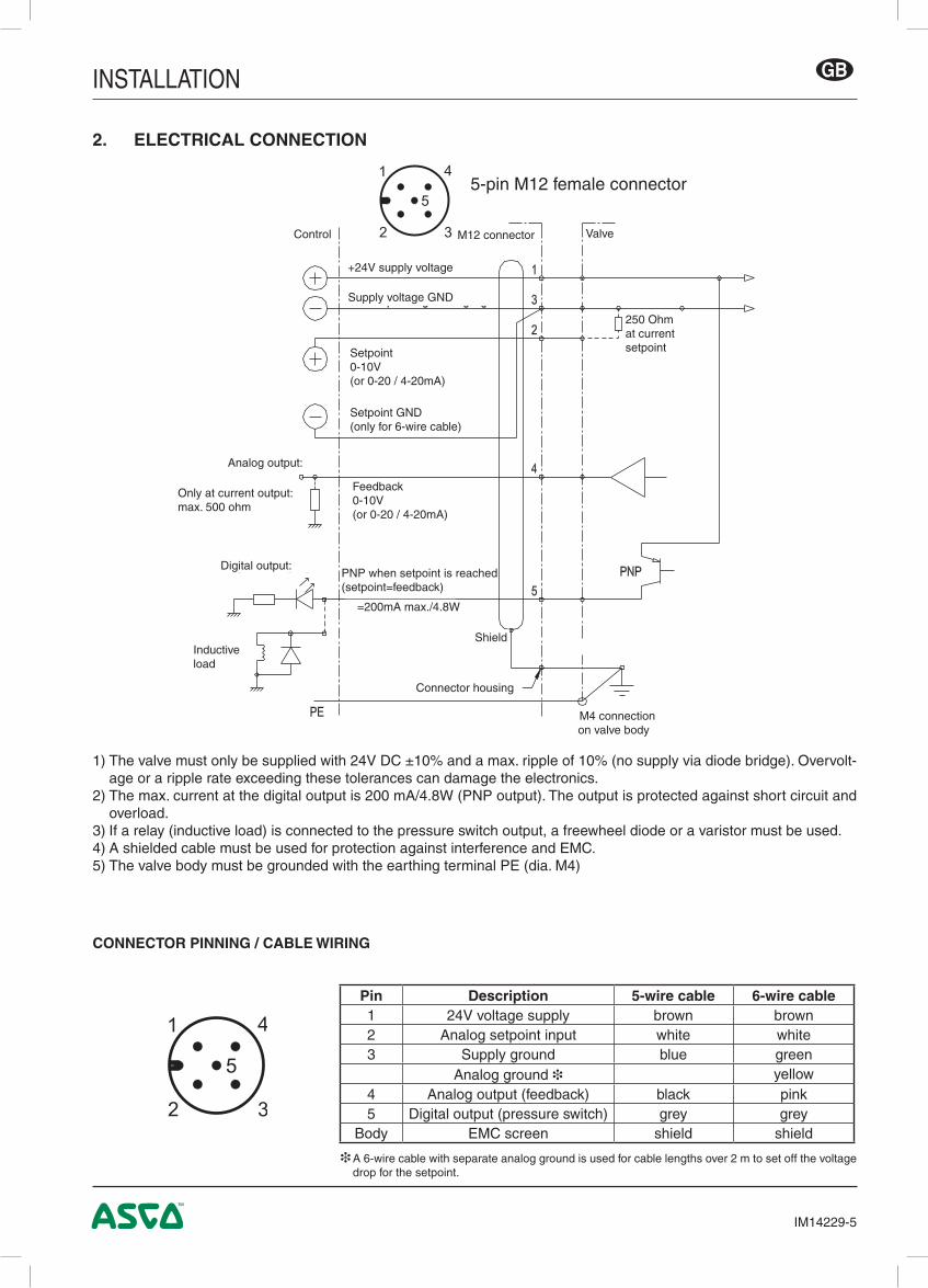
1) The valve must only be supplied with 24V DC ±10% and a max. ripple of 10% (no supply via diode bridge). Overvolt-age or a ripple rate exceeding these tolerances can damage the electronics.
2) The max. current at the digital output is 200 mA/4.8W (PNP output). The output is protected against short circuit and overload.
3) If a relay (inductive load) is connected to the pressure switch output, a freewheel diode or a varistor must be used.4) A shielded cable must be used for protection against interference and EMC.5) The valve body must be grounded with the earthing terminal PE (dia. M4)
2. ELECTRICAL CONNECTION
CONNECTOR PINNING / CABLE WIRING
1
2 3
5
4
5-pin M12 female connector
250 Ohm at currentsetpoint
ValveM12 connector
+24V supply voltage
Supply voltage GND
Setpoint GND(only for 6-wire cable)
Setpoint0-10V(or 0-20 / 4-20mA)
Feedback0-10V(or 0-20 / 4-20mA)
Control
Analog output:
Only at current output: max. 500 ohm
PNP when setpoint is reached (setpoint=feedback)
Shield
=200mA max./4.8W
Inductive load
M4 connection on valve body
Connector housing
Digital output:
❉ A 6-wire cable with separate analog ground is used for cable lengths over 2 m to set off the voltage drop for the setpoint.
Pin Description 5-wire cable 6-wire cable1 24V voltage supply brown brown2 Analog setpoint input white white3 Supply ground blue green
Analog ground ❉ yellow4 Analog output (feedback) black pink5 Digital output (pressure switch) grey grey
Body EMC screen shield shield
INSTALLATION
IM14229-6
GB
2
PE ØM4
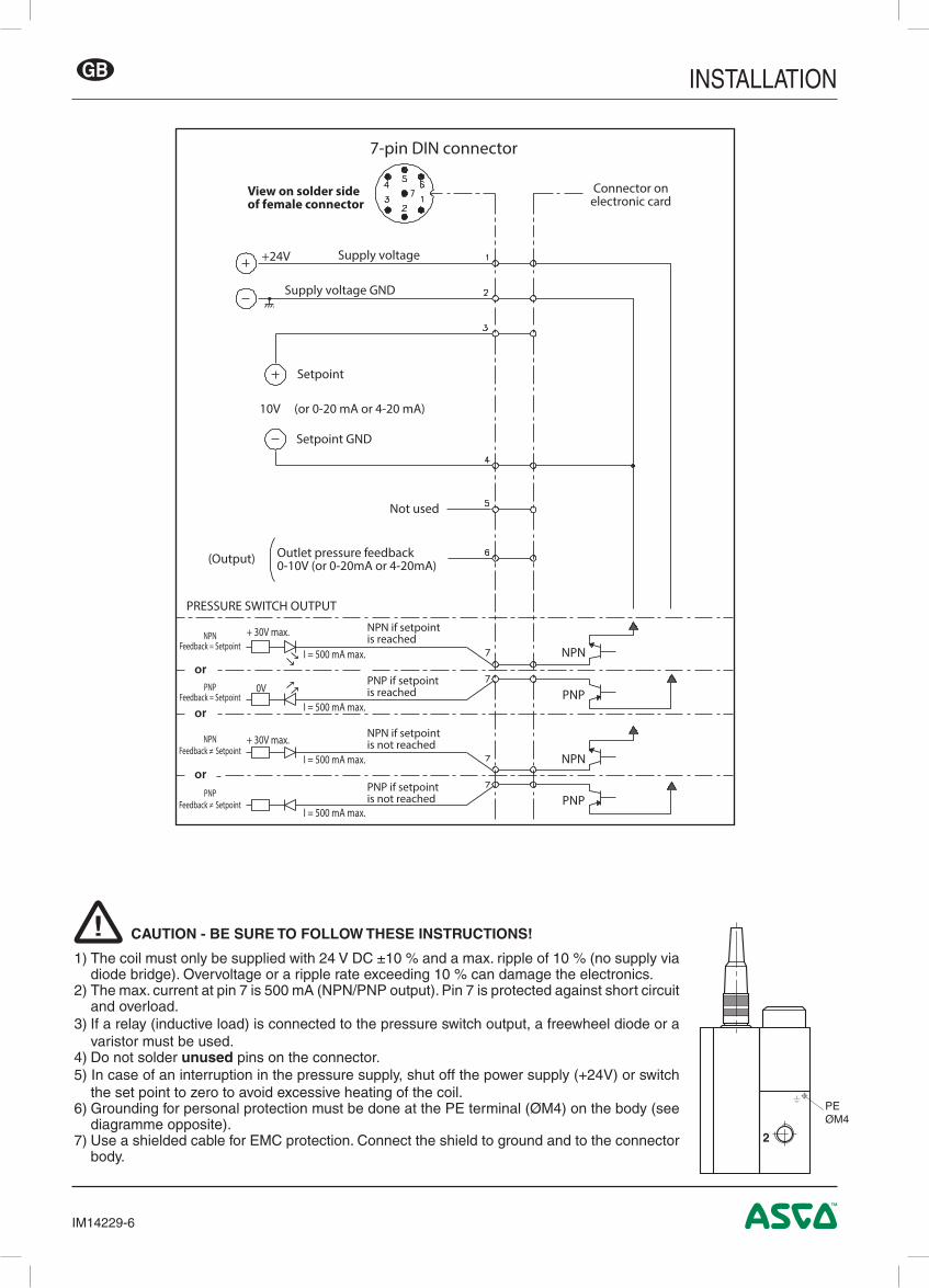
CAUTION - BE SURE TO FOLLOW THESE INSTRUCTIONS!
1) The coil must only be supplied with 24 V DC ±10 % and a max. ripple of 10 % (no supply via diode bridge). Overvoltage or a ripple rate exceeding 10 % can damage the electronics.
2) The max. current at pin 7 is 500 mA (NPN/PNP output). Pin 7 is protected against short circuit and overload.
3) If a relay (inductive load) is connected to the pressure switch output, a freewheel diode or a varistor must be used.
4) Do not solder unused pins on the connector.5) In case of an interruption in the pressure supply, shut off the power supply (+24V) or switch
the set point to zero to avoid excessive heating of the coil.6) Grounding for personal protection must be done at the PE terminal (ØM4) on the body (see
diagramme opposite).7) Use a shielded cable for EMC protection. Connect the shield to ground and to the connector
body.
!
+24V Supply voltage
Supply voltage GND
Setpoint
10V (or 0-20 mA or 4-20 mA)
Setpoint GND
(Output)
Not used
Outlet pressure feedback0-10V (or 0-20mA or 4-20mA)
PRESSURE SWITCH OUTPUT
NPN if setpointis reached
PNP if setpointis reached
NPN if setpointis not reached
PNP if setpointis not reached
NPNFeedback = Setpoint
+ 30V max.
+ 30V max.
0V
I = 500 mA max.
I = 500 mA max.
I = 500 mA max.
I = 500 mA max.
PNPFeedback = Setpoint
NPNFeedback ≠ Setpoint
PNPFeedback ≠ Setpoint
Connector onelectronic card
NPN
PNP
NPN
PNP
7-pin DIN connector
View on solder sideof female connector
or
or
or
INSTALLATION
IM14229-7
GB
10 V20 mA20 mA
004
5 V10 mA12 mA
50 mV0.1 mA4.08 mA
+50% PMR
-50% PMR
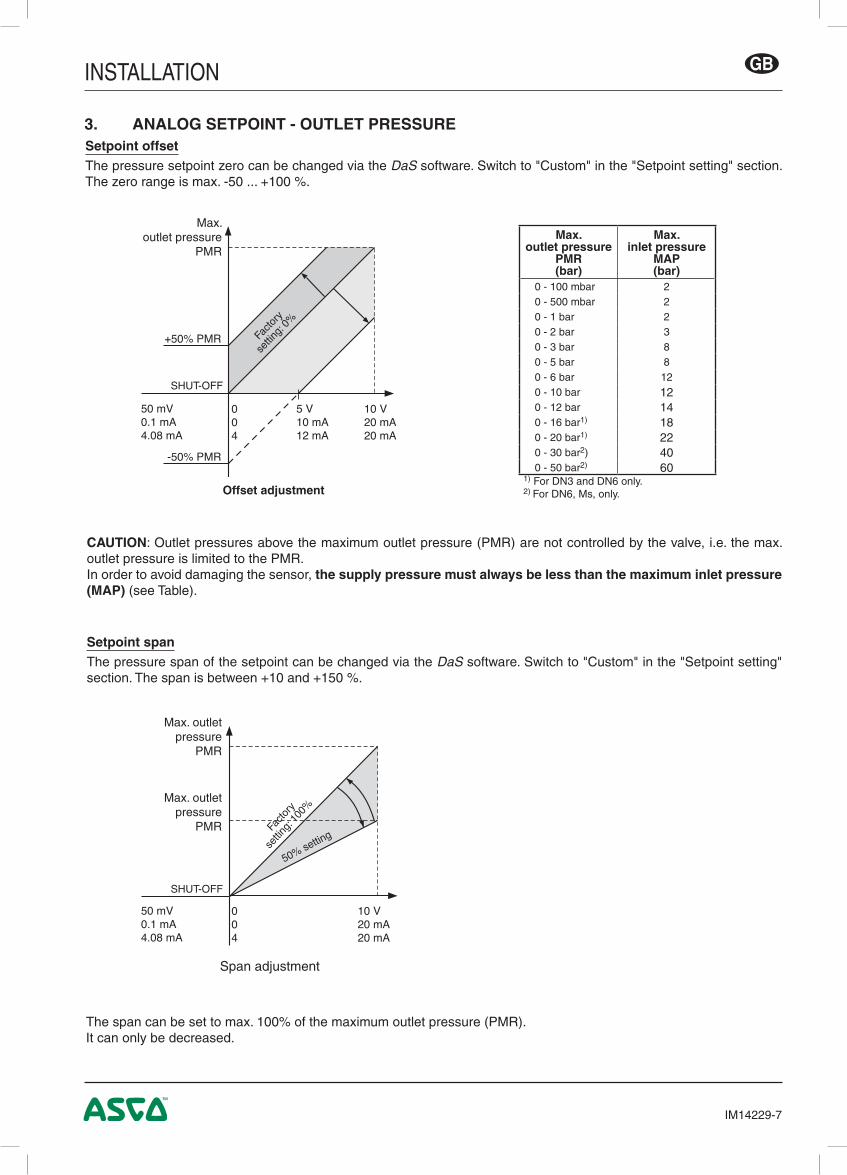
Setpoint spanThe pressure span of the setpoint can be changed via the DaS software. Switch to "Custom" in the "Setpoint setting" section. The span is between +10 and +150 %.
CAUTION: Outlet pressures above the maximum outlet pressure (PMR) are not controlled by the valve, i.e. the max. outlet pressure is limited to the PMR.In order to avoid damaging the sensor, the supply pressure must always be less than the maximum inlet pressure (MAP) (see Table).
The span can be set to max. 100% of the maximum outlet pressure (PMR).It can only be decreased.
3. ANALOG SETPOINT - OUTLET PRESSURESetpoint offsetThe pressure setpoint zero can be changed via the DaS software. Switch to "Custom" in the "Setpoint setting" section. The zero range is max. -50 ... +100 %.
Span adjustment
Offset adjustment
Max. outlet pressure
PMR
SHUT-OFF
Max.outlet pressure
PMR(bar)
Max.inlet pressure
MAP(bar)
0 - 100 mbar 20 - 500 mbar 20 - 1 bar 20 - 2 bar 30 - 3 bar 80 - 5 bar 80 - 6 bar 120 - 10 bar 120 - 12 bar 140 - 16 bar1) 180 - 20 bar1) 220 - 30 bar2) 400 - 50 bar2) 60
1) For DN3 and DN6 only.2) For DN6, Ms, only.
10 V20 mA20 mA
004
50 mV0.1 mA4.08 mA
Facto
ry
settin
g: 0%
Max. outlet pressure
PMR
SHUT-OFF
Max. outlet pressure
PMR Facto
ry
settin
g: 10
0%
50% setting
INSTALLATION
IM14229-8
GB
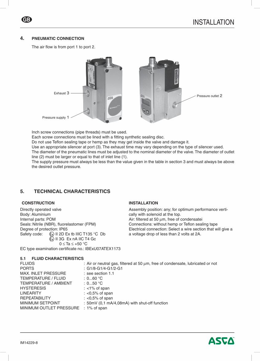
4. PNEUMATIC CONNECTION
The air flow is from port 1 to port 2.
Inch screw connections (pipe threads) must be used.Each screw connections must be lined with a fitting synthetic sealing disc.Do not use Teflon sealing tape or hemp as they may get inside the valve and damage it.Use an appropriate silencer at port (3). The exhaust time may vary depending on the type of silencer used.The diameter of the pneumatic lines must be adjusted to the nominal diameter of the valve. The diameter of outlet line (2) must be larger or equal to that of inlet line (1). The supply pressure must always be less than the value given in the table in section 3 and must always be above the desired outlet pressure.
5. TECHNICAL CHARACTERISTICS
CONSTRUCTION INSTALLATION
Directly operated valveBody: AluminiumInternal parts: POMSeals: Nitrile (NBR), fluorelastomer (FPM)Degree of protection: IP65Safety code: q II 2D Ex tb IIIC T135 °C Db q II 3G Ex nA IIC T4 Gc 0 ≤ Ta ≤ +50 °CEC type examination certificate no.: IBExU07ATEX1173
Assembly position: any; for optimum performance verti-cally with solenoid at the top.Air: filtered at 50 µm, free of condensateiConnections: without hemp or Teflon sealing tapeElectrical connection: Select a wire section that will give a a voltage drop of less than 2 volts at 2A.
5.1 FLUID CHARACTERISTICSFLUIDS : Air or neutral gas, filtered at 50 µm, free of condensate, lubricated or notPORTS : G1/8-G1/4-G1/2-G1MAX. INLET PRESSURE : see section 1.1TEMPERATURE / FLUID : 0...60 °CTEMPERATURE / AMBIENT : 0...50 °CHYSTERESIS : <1% of spanLINEARITY : <0,5% of spanREPEATABILITY : <0,5% of spanMINIMUM SETPOINT : 50mV (0,1 mA/4,08mA) with shut-off functionMINIMUM OUTLET PRESSURE : 1% of span
Pressure supply 1
Exhaust 3Pressure outlet 2
INSTALLATION
IM14229-9
GB
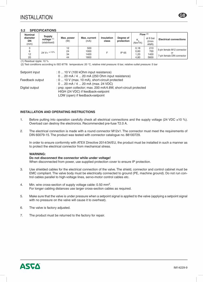
Setpoint input : 0 ... 10 V (100 kOhm input resistance) 0 ... 20 mA / 4 ... 20 mA (250 Ohm input resistance)Feedback output : 0 ... 10 V (max. 10 mA), short-circuit protected 0 ... 20 mA / 4 ... 20 mA (max. 24 VDC)Digital output : pnp; open collector; max. 200 mA/4.8W, short-circuit protected HIGH (24 VDC) if feedback=setpoint LOW (open) if feedback≠setpoint
5.2 SPECIFICATIONSNominaldiameter
DN(mm)
Supply voltage (1)
(stabilised)
Max. power(W)
Max. current(mA)
Insulation class
Degree of protection
Flow (2)
Electrical connectionsKV
(Nm3/h)
at 6 bar(l/min ANR)
361220
24 V= +/-10%
12243444
500 1000 1400 1800
F IP 65
0,180,601,204,80
210 700 1400 5600
5-pin female M12 connectoror
7-pin female DIN connector
(1) Residual ripple: 10 %(2) Test conditions according to ISO 8778: temperature: 20 °C, relative inlet pressure: 6 bar, relative outlet pressure: 5 bar
INSTALLATION AND OPERATING INSTRUCTIONS
1. Before putting into operation carefully check all electrical connections and the supply voltage (24 VDC ±10 %). Overload can destroy the electronics. Recommended pre-fuse T2.0 A.
2. The electrical connection is made with a round connector M12x1. The connector must meet the requirements of DIN 60079-15. The product was tested with connector catalogue no. 88100729.
In order to ensure conformity with ATEX Directive 2014/34/EU, the product must be installed in such a manner as to protect the electrical connector from mechanical stress.
WARNING: Do not disconnect the connector while under voltage! When disconnected from power, use supplied protection cover to ensure IP protection.
3. Use shielded cables for the electrical connection of the valve. The shield, connector and control cabinet must be EMC compliant. The valve body must be electrically connected to ground (PE, machine ground). Do not run con-trol cables parallel to high-voltage lines, servo-motor control cables etc.
4. Min. wire cross-section of supply voltage cable: 0.50 mm2. For longer cabling distances use larger cross-section cables as required.
5. Make sure that the valve is under pressure when a setpoint signal is applied to the valve (applying a setpoint signal with no pressure on the valve will cause it to overheat).
6. The valve is factory adjusted.
7. The product must be returned to the factory for repair.
INSTALLATION
IM14229-10
GB
6. ACCESSORIES
7. MAINTENANCE AND CARE
No special maintenance or care required.
description catalogue number
Straight M12 female connector, 5 pins, with screw terminals 88100256
Right-angle M12 female connector, 5 pins, with screw terminals 88100725
Supply cable 2 m, 2 x 0,25 mm², straight connector 88100726
Supply cable 2 m, 2 x 0,25 mm², right-angle connector 88100727
Supply cable 5 m, 6 x 0,56 mm², straight connector 88100728
Supply cable 5 m, 6 x 0,56 mm², right-angle connector 88100729
Supply cable 10 m, 6 x 0,56 mm², straight connector 88100730
Supply cable 10 m, 6 x 0,56 mm², right-angle connector 88100731
RS 232 cable converter; 2 m cable with 9-pin Sub-D (screw connector) 88100970
DaS 5.00, Data Acquisition Software für SentronicPLUS Available for download at www.asconumatics.eu
WARNING NOTESThese products are intended for use in industrial compressed air systems only. Do not use these products where pres-sures and temperatures can exceed those listed under SPECIFICATIONS. Please also see the corresponding product specification sheets.
Before using these products with fluids other than those specified, for non-industrial applications, life-support systems, or other applications not within published specifications, consult ASCO Numatics.
Through misuse, age, or malfunction, components used in fluid power systems can fail in various modes.The system designer is warned to consider the failure modes of all component parts used in fluid power sys-tems and to provide adequate safeguards to prevent personal injury or damage to equipment in the event of such failure.System designers must provide a warning to end users in the operating manual if protection against a failure mode can-not be adequately ensured.
System designers and end users are cautioned to review specific warnings found in instruction sheets packed and shipped with these products.
INSTALLATION
IM14229-11
GB
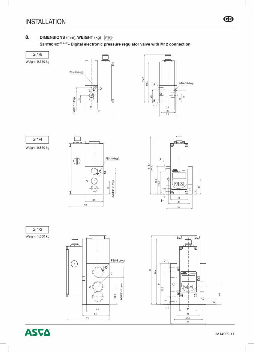
8. DIMENSIONS (mm), WEIGHT (kg)
SentronicPLUS - Digital electronic pressure regulator valve with M12 connection
Weight: 1,650 kg
G 1/4
Weight: 0,850 kg
G 1/2
G 1/8
Weight: 0,550 kg
PE(4-8 deep)3x
G1/
8"-8
dee
p
2xM4-10 deep
PE(4-8 deep)
3xG
1/4"
-12
deep
3xG
1/2"
-14
deep
PE(4-8 deep)
INSTALLATION
IM14229-12
GB
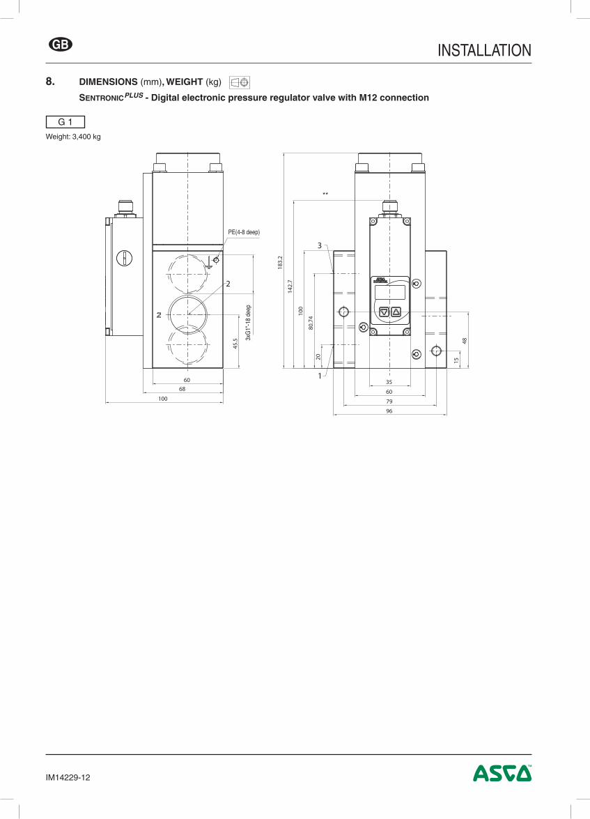
8. DIMENSIONS (mm), WEIGHT (kg)
SentronicPLUS - Digital electronic pressure regulator valve with M12 connection
G 1
Weight: 3,400 kg
**
3xG
1"-1
8 de
ep
PE(4-8 deep)
INSTALLATION
IM14229-13
GB
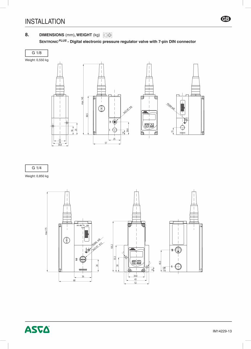
G 1/4
Weight: 0,850 kg
G 1/8
Weight: 0,550 kg
max
. 145
PE(M4; 8)
18 25
34.82925
10
26.6
80.5 3xG1/8";
8
5725
15
max
.175
3xG1/4"; 12
PE(M4; 8)
3668
105.2
55.3
45.3
11.02
34.84352
10
30
*
*
26
8. DIMENSIONS (mm), WEIGHT (kg)
SentronicPLUS - Digital electronic pressure regulator valve with 7-pin DIN connector
INSTALLATION
IM14229-14
GB
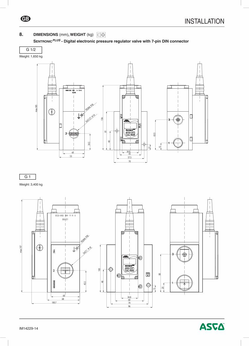
G 1
Weight: 3,400 kg
max
.197
100.7
6068
45.5
3xG1"; 18
PE(M4; 8)
100
8020
48
15
7996
6034.8
Weight: 1,650 kg
G 1/2
max
.185
4553
34.5
136
81
63.5
15
40
12
57.570
4534.8
PE(M4; 8)
3xG1/2"; 14
8. DIMENSIONS (mm), WEIGHT (kg)
SentronicPLUS - Digital electronic pressure regulator valve with 7-pin DIN connector
INSTALLATION
IM14229-15
GB
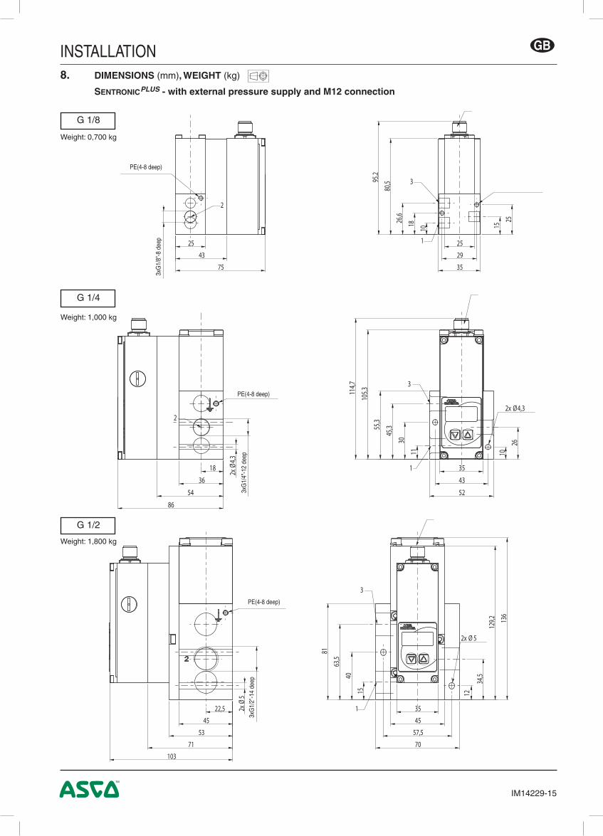
8. DIMENSIONS (mm), WEIGHT (kg)
SentronicPLUS - with external pressure supply and M12 connection
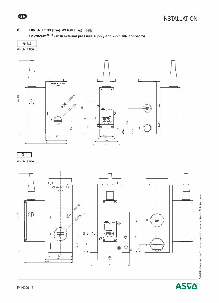
Weight: 1,800 kg
G 1/4
Weight: 1,000 kg
G 1/2
G 1/8
Weight: 0,700 kg
25
29
10
1826,6
15
25
35
80,595
,2
25
43
75
3
1
2
35
45
57,5
70
1215
34,540
63,5
81
129,2 13
6
2x Ø 5
22,5
45
53
71
103
2x Ø
5
3
1
PE(4-8 deep)
3xG
1/8"
-8 d
eep
PE(4-8 deep)
3xG
1/4"
-12
deep
3xG
1/2"
-14
deep
PE(4-8 deep)
35
52
43
11 10
2630
45,355
,3
114,7
2x Ø4,3
105,3
18
36
54
86
2x Ø
4,3
3
1
2
INSTALLATION
IM14229-16
GB
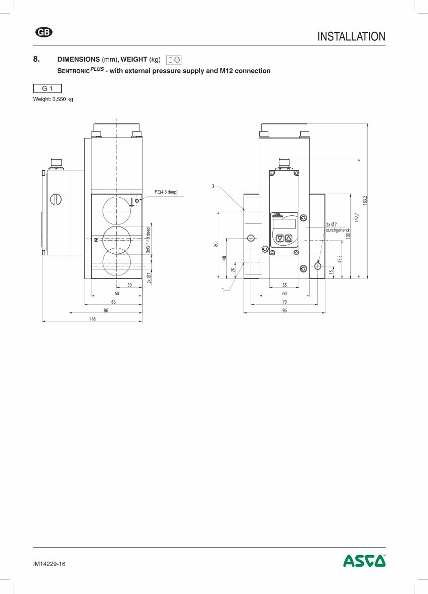
8. DIMENSIONS (mm), WEIGHT (kg)
SentronicPLUS - with external pressure supply and M12 connection
G 1
Weight: 3,550 kg
30
60
68
86
118
35
60
79
96
20 15
45,548
80
100
142,7
183,2
2x Ø7
2x Ø
7
1
3
3xG
1"-1
8 de
ep
PE(4-8 deep)
durchgehend
INSTALLATION
IM14229-17
GB
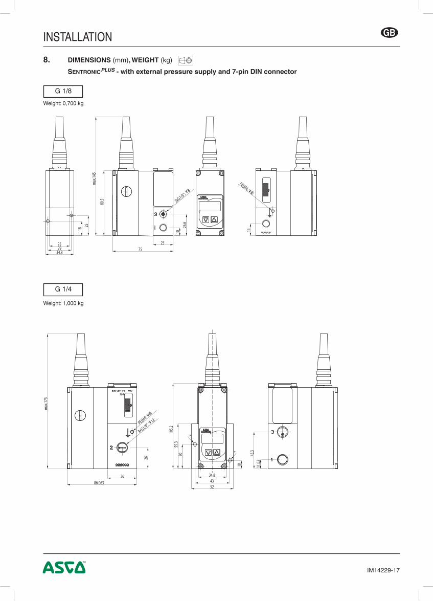
8. DIMENSIONS (mm), WEIGHT (kg)
SentronicPLUS - with external pressure supply and 7-pin DIN connector
G 1/4
Weight: 1,000 kg
G 1/8
Weight: 0,700 kg
max
.145
PE(M4; 8)
1825
34.82925
1026
.6
80.5 3xG1/8";
8
7525
15
max
.175
3xG1/4"; 12PE(M4;
8)
3686.063
105.2
55.3
45.3
11.02
34.84352
10
30
*
*
26
INSTALLATION
IM14229-18
GB
8. DIMENSIONS (mm), WEIGHT (kg)
SentronicPLUS - with external pressure supply and 7-pin DIN connector
7. Maintenance et entretien ............................................................................................................................ 28
8. Encombrements et masses ....................................................................................................................... 11
ATTENTION! Des conditions d’exploitation dangereuses peuvent se développer en utilisant l’interface de programmation sur la vanneétant donné que la vanne ne réagira éventuellement plus à la consigne analogique appliquée.Assurer une protection contre des mouvements incontrôlés de l’équipement lors de la mise en service de la vanne et avant d’effectuer des modifications sur les réglages de la vanne.
E S D
!
Ce produit contient des composants électroniques sensibles aux décharges électrostatiques. Tout contact des connexions par une personne ou un objet chargé d’électricité statique pourrait entraîner la mise en panne ou la destruction de l’appareil.Pour réduire les risques de décharges électrostatiques, veuillez respecter les recommandations et précautions de manipulation définies par la norme EN100 015-1, avant toute intervention sur ce produit.Ne jamais brancher ou débrancher l’appareil lorsqu’il est sous tension.
NOTESLes informations contenues dans le présent manuel sont susceptibles d’être modifiées sans préavis.ASCO NUMATICS ne peut être tenu responsable des omissions techniques ou rédactionnelles, ni des dommages accidentels ou consécutifs à la fourniture ou l’utilisation du présent document.LE PRESENT MANUEL CONTIENT DES INFORMATIONS PROTEGEES PAR COPYRIGHT, AUCUNE PARTIE DU PRESENT DOCUMENT NE PEUT ETRE PHOTOCOPIEE OU REPRODUITE SOUS QUELQUE FORME QUE CE SOIT SANS AUTORISATION ECRITE PREALABLE DE ASCO NUMATICS.
Ce produit est conforme aux exigences essentielles de la Directive 2014/30/UE sur la Compatibilité Electromagnétique, et amendements. Une déclaration de conformité peut être fournie sur simple demande.
Veuillez nous indiquer les références ou codes des produits concernés.
Par la présente nous déclarons que le produit décrit dans ce manuel d’installation, est destiné pour être installé dans une machine ou à être assemblé à une autre machine: Toutefois il est interdit de mettre le produit en fonctionnement tant que la machine dans laquelle il est déstiné à être incorporé ou l’ensemble de machines solidaires auquel il doit être assemblé n’aura pas été déclaré conforme aux dispositions de la Directive Machines 2006/42/CE.Toutes opérations de manutention, d’installation et de mise en service, ainsi que la mise au point et le réglage doivent être effectués uniquement par un personnel qualifié et autorisé.
ATTENTIONRESPECTER LES PRECAUTIONS
DE MANIPULATION DES PRODUITS SENSIBLES
AUX DECHARGESELECTROSTATIQUES
INSTALLATION
IM14229-21
FR
1. DESCRIPTIONSentronicPLUS à boucle de régulation interne numérique associe une technologie pneumatique innovante et une électronique integrée. Cette série de distributeurs permet de réguler avec précision les valeurs de pression, débit, force, vitesse, et de positionnement linéaire ou angulaire. La série de vannes SentronicPLUS vient compléter la série SentronicD.La SentronicPLUS est disponible en 14 plages de pression standard allant de 100 mbar à 50 bar. La gamme comprend quatre diamètres nominaux pour couvrir une large plage de débit. Les versions en divers matériaux de corps et de garnitures d'étanchéité sont destinées à être utilisées dans les domaines les plus divers, dont l'industrie agro-alimentaire, la technologie médicale ...La régulation en double boucle (cascade) permet de réaliser des boucles de régulation complexes via le logiciel DaS (Data Acquisition Software). La commande numérique offre maintes avantages lors de l'installation et de la mise en service ainsi que des possibilités étendues d'adapter la SentronicPLUS aux applications les plus diverses..• Les diamètres des passage sont équivalents sur la voie d'alimentation en pression comme sur celle d'échap-
pement assurant ainsi des temps de réponse très courts tant en augmentation qu'en réduction de pression.• Contrôle de la pression numérique en boucle fermée : Un capteur de pression interne compare la valeur de
pression de consigne à la pression de sortie. La pression de sortie est régulée en temps réel.• Les paramètres peuvent être changés avec le logiciel optionnel DaS (à partir de la version 5.00). Le pro-
gramme DaS (Logiciel d’Acquisition de Données ou Data Acquisition Software) permet de modifier tous les paramètres de régulation de la vanne. Cette flexibilité permet d’adapter la vanne aux applications les plus variées et permet l’optimisation du temps de réponse, de l'overshoot et de la précision.
• Après avoir réglé les paramètres optimums, vous pouvez les sauvegarder dans un fichier de projet pour votre utilisation personnelle ou les envoyer à notre Support Technique pour une future production en série .
• La version à connecteur M12 sans affichage est certifiée ATEX :q II 2D Ex tb IIIC T135 °C Dbq II 3G Ex nA IIC T4 Gc
0 ≤ Ta ≤ +50 °CNo de l'attestation CE de type : IBExU07ATEX1173
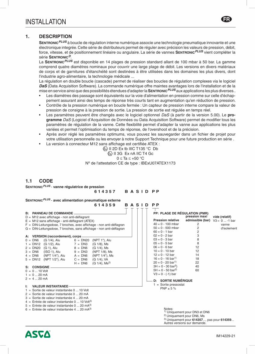
1.1 CODESentronicPLUS - vanne régulatrice de pression 6 1 4 3 5 7 B A S I D P P
SentronicPLUS - avec alimentation pneumatique externe 6 1 4 3 5 9 B A S I D P P
B: PANNEAU DE COMMANDED = M12 avec affichage - non anti-déflagrantE = M12 sans affichage - anti-déflagrant (ATEX)F = DIN-Leitungsdose, 7 broches, avec affichage - non anti-déflagranG = DIN-Leitungsdose, 7 broches, sans affichage - non anti-déflagran
A: VERSION (raccordement), corps0 = DN6 (G 1/4), Alu 6 = DN20 (NPT 1"), Alu1 = DN12 (G 1/2), Alu 7 = DN3 (G 1/8), Ms2 = DN20 (G 1), Alu 8 = DN6 (G 1/4), Ms3 = DN6 (ISO 1), Alu 9 = DN3 (NPT 1/8), Ms4 = DN6 (NPT 1/4"), Alu A = DN6 (NPT 1/4"), Ms5 = DN12 (NPT 1/2"), Alu C = DN6 (G 1/4), VA H = DN6 (G 1/4), Ms2)
Notes:1) Uniquement pour DN3 et DN62) Uniquement pour DN6, Ms3) Uniquement pour 614357..., pas pour 614359...Autres versions sur demande.
vide (relatif)V3 = 0 ... -1 bar vanne
d'isolement
INSTALLATION
IM14229-22
FR
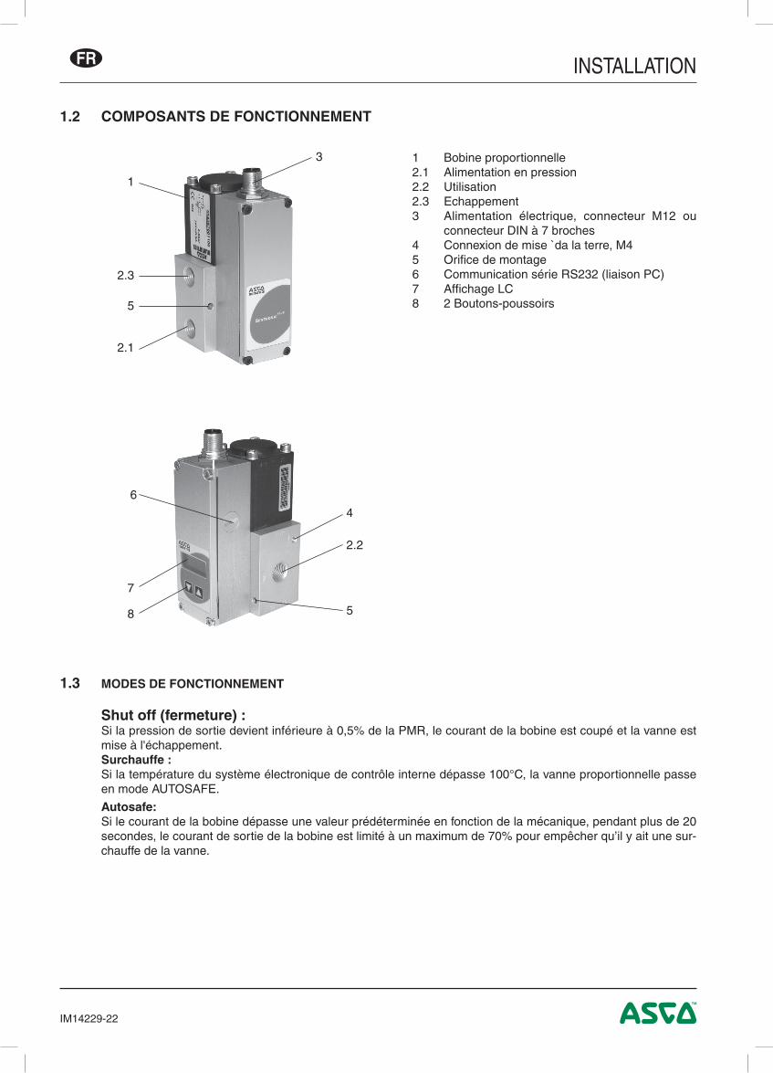
1.2 COMPOSANTS DE FONCTIONNEMENT
1.3 MODES DE FONCTIONNEMENT
Shut off (fermeture) :Si la pression de sortie devient inférieure à 0,5% de la PMR, le courant de la bobine est coupé et la vanne est mise à l'échappement.Surchauffe :
Si la température du système électronique de contrôle interne dépasse 100°C, la vanne proportionnelle passe en mode AUTOSAFE.
Autosafe: Si le courant de la bobine dépasse une valeur prédéterminée en fonction de la mécanique, pendant plus de 20
secondes, le courant de sortie de la bobine est limité à un maximum de 70% pour empêcher qu’il y ait une sur-chauffe de la vanne.
1 Bobine proportionnelle2.1 Alimentation en pression2.2 Utilisation2.3 Echappement3 Alimentation électrique, connecteur M12 ou
connecteur DIN à 7 broches4 Connexion de mise `da la terre, M45 Orifice de montage6 Communication série RS232 (liaison PC)7 Affichage LC8 2 Boutons-poussoirs
3
1
2.1
5
2.3
6
4
2.2
5
7
8
INSTALLATION
IM14229-23
FR
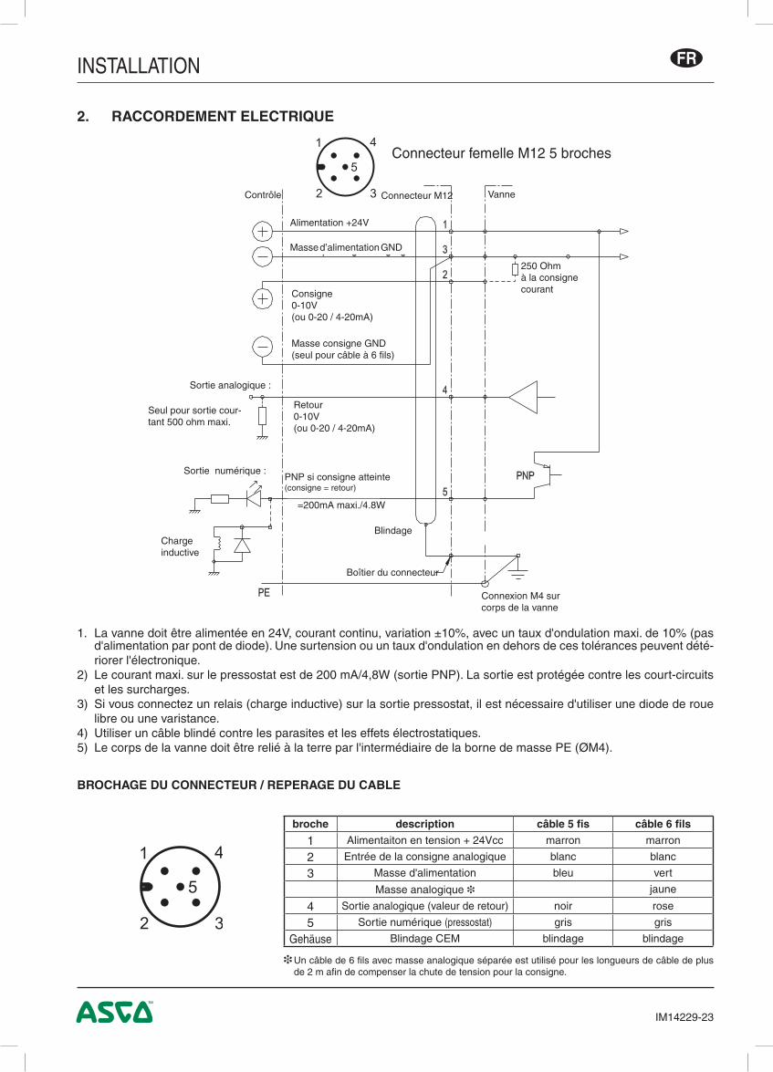
1. La vanne doit être alimentée en 24V, courant continu, variation ±10%, avec un taux d'ondulation maxi. de 10% (pas d'alimentation par pont de diode). Une surtension ou un taux d'ondulation en dehors de ces tolérances peuvent dété-riorer l'électronique.
2) Le courant maxi. sur le pressostat est de 200 mA/4,8W (sortie PNP). La sortie est protégée contre les court-circuits et les surcharges.
3) Si vous connectez un relais (charge inductive) sur la sortie pressostat, il est nécessaire d'utiliser une diode de roue libre ou une varistance.
4) Utiliser un câble blindé contre les parasites et les effets électrostatiques. 5) Le corps de la vanne doit être relié à la terre par l'intermédiaire de la borne de masse PE (ØM4).
2. RACCORDEMENT ELECTRIQUE
BROCHAGE DU CONNECTEUR / REPERAGE DU CABLE
❉ Un câble de 6 fils avec masse analogique séparée est utilisé pour les longueurs de câble de plus de 2 m afin de compenser la chute de tension pour la consigne.
broche description câble 5 fis câble 6 fils
1 Alimentaiton en tension + 24Vcc marron marron
2 Entrée de la consigne analogique blanc blanc
3 Masse d'alimentation bleu vert
Masse analogique ❉ jaune
4 Sortie analogique (valeur de retour) noir rose
5 Sortie numérique (pressostat) gris gris
Gehäuse Blindage CEM blindage blindage
1
2 3
5
4
Connecteur femelle M12 5 broches
250 Ohm à la consignecourant
VanneConnecteur M12
Alimentation +24V
Masse d’alimentation GND
Masse consigne GND(seul pour câble à 6 fils)
Consigne0-10V(ou 0-20 / 4-20mA)
Retour0-10V(ou 0-20 / 4-20mA)
Contrôle
Sortie analogique :
Seul pour sortie cour-tant 500 ohm maxi.
PNP si consigne atteinte(consigne = retour)
Blindage
=200mA maxi./4.8W
Charge inductive
Connexion M4 sur corps de la vanne
Boîtier du connecteur
Sortie numérique :
INSTALLATION
IM14229-24
FR
2
PE ØM4
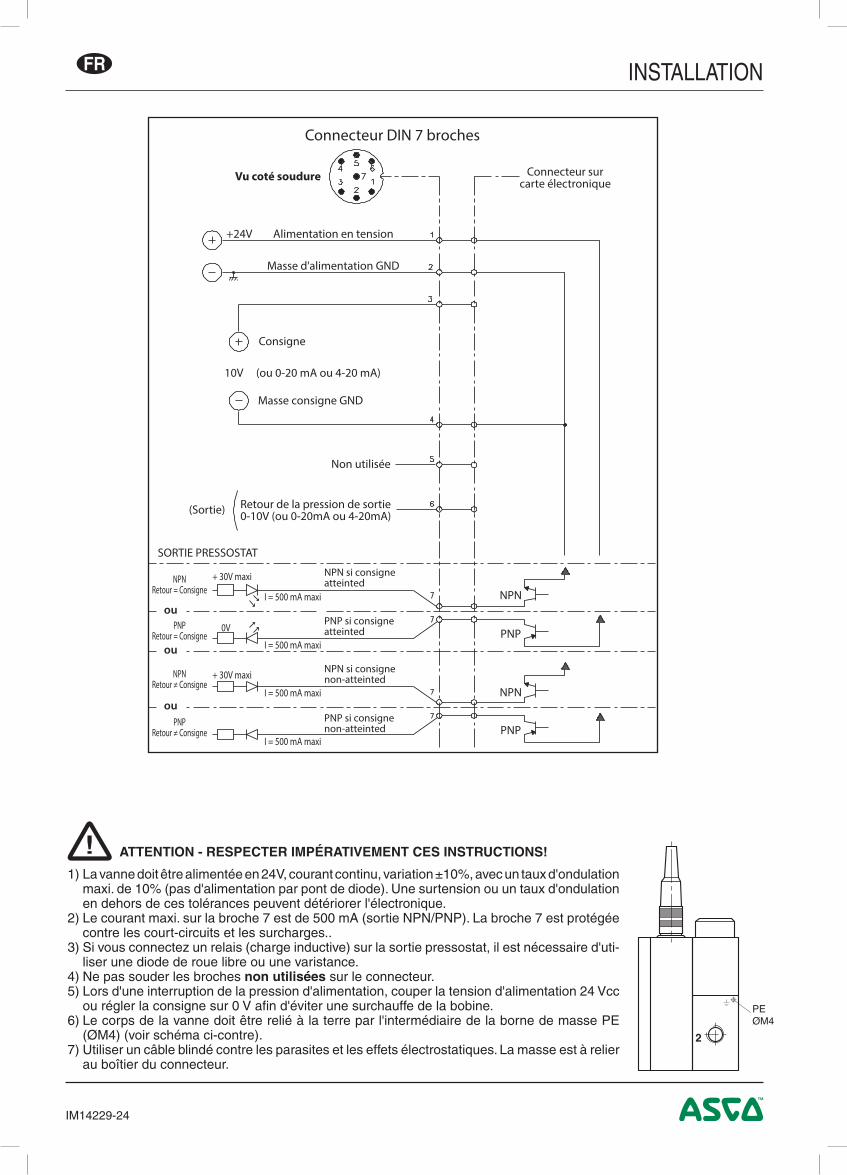
ATTENTION - RESPECTER IMPÉRATIVEMENT CES INSTRUCTIONS!
1) La vanne doit être alimentée en 24V, courant continu, variation ±10%, avec un taux d'ondulation maxi. de 10% (pas d'alimentation par pont de diode). Une surtension ou un taux d'ondulation en dehors de ces tolérances peuvent détériorer l'électronique.
2) Le courant maxi. sur la broche 7 est de 500 mA (sortie NPN/PNP). La broche 7 est protégée contre les court-circuits et les surcharges..
3) Si vous connectez un relais (charge inductive) sur la sortie pressostat, il est nécessaire d'uti-liser une diode de roue libre ou une varistance.
4) Ne pas souder les broches non utilisées sur le connecteur.5) Lors d'une interruption de la pression d'alimentation, couper la tension d'alimentation 24 Vcc
ou régler la consigne sur 0 V afin d'éviter une surchauffe de la bobine.6) Le corps de la vanne doit être relié à la terre par l'intermédiaire de la borne de masse PE
(ØM4) (voir schéma ci-contre).7) Utiliser un câble blindé contre les parasites et les effets électrostatiques. La masse est à relier
au boîtier du connecteur.
!
+24V Alimentation en tension
Masse d'alimentation GND
Consigne
10V (ou 0-20 mA ou 4-20 mA)
Masse consigne GND
(Sortie)
Non utilisée
Retour de la pression de sortie0-10V (ou 0-20mA ou 4-20mA)
SORTIE PRESSOSTAT
NPN si consigneatteinted
PNP si consigneatteinted
NPN si consignenon-atteinted
PNP si consignenon-atteinted
NPNRetour = Consigne
+ 30V maxi
+ 30V maxi
0V
I = 500 mA maxi
I = 500 mA maxi
I = 500 mA maxi
I = 500 mA maxi
PNPRetour = Consigne
NPNRetour ≠ Consigne
PNPRetour ≠ Consigne
Connecteur surcarte électronique
NPN
PNP
NPN
PNP
Connecteur DIN 7 broches
Vu coté soudure
ou
ou
ou
INSTALLATION
IM14229-25
FR
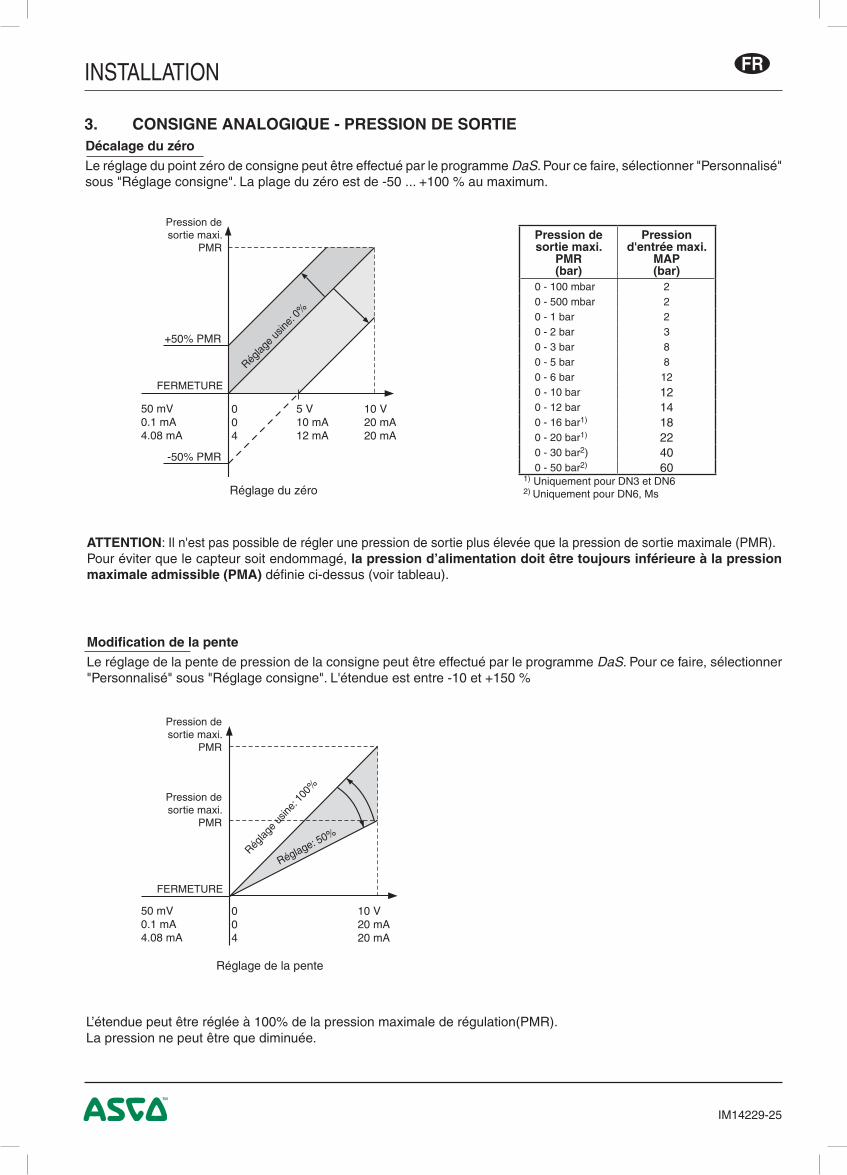
Modification de la pente
Le réglage de la pente de pression de la consigne peut être effectué par le programme DaS. Pour ce faire, sélectionner "Personnalisé" sous "Réglage consigne". L'étendue est entre -10 et +150 %
ATTENTION: Il n'est pas possible de régler une pression de sortie plus élevée que la pression de sortie maximale (PMR).Pour éviter que le capteur soit endommagé, la pression d’alimentation doit être toujours inférieure à la pression maximale admissible (PMA) définie ci-dessus (voir tableau).
L’étendue peut être réglée à 100% de la pression maximale de régulation(PMR).La pression ne peut être que diminuée.
3. CONSIGNE ANALOGIQUE - PRESSION DE SORTIEDécalage du zéro
Le réglage du point zéro de consigne peut être effectué par le programme DaS. Pour ce faire, sélectionner "Personnalisé" sous "Réglage consigne". La plage du zéro est de -50 ... +100 % au maximum.
Réglage de la pente
Réglage du zéro
Pression de sortie maxi.
PMR
FERMETURE
Pression desortie maxi.
PMR(bar)
Pression d'entrée maxi.
MAP(bar)
0 - 100 mbar 20 - 500 mbar 20 - 1 bar 20 - 2 bar 30 - 3 bar 80 - 5 bar 80 - 6 bar 120 - 10 bar 120 - 12 bar 140 - 16 bar1) 180 - 20 bar1) 220 - 30 bar2) 400 - 50 bar2) 60
1) Uniquement pour DN3 et DN62) Uniquement pour DN6, Ms
10 V20 mA20 mA
004
5 V10 mA12 mA
50 mV0.1 mA4.08 mA
+50% PMR
-50% PMR
10 V20 mA20 mA
004
50 mV0.1 mA4.08 mA
Réglag
e usin
e: 0%
Pression de sortie maxi.
PMR
FERMETURE
Pression de sortie maxi.
PMR
Réglag
e us
ine: 1
00%
Réglage: 50%
INSTALLATION
IM14229-26
FR
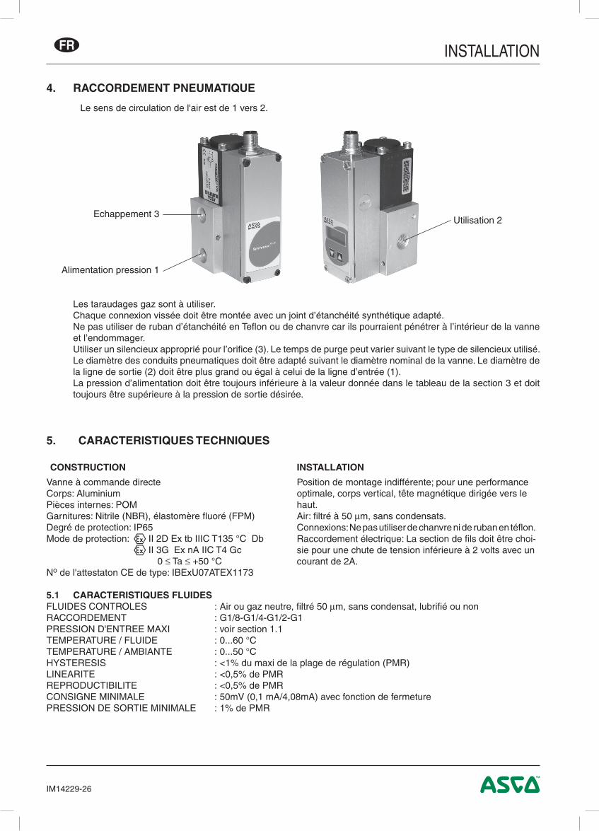
4. RACCORDEMENT PNEUMATIQUE
Le sens de circulation de l'air est de 1 vers 2.
Les taraudages gaz sont à utiliser. Chaque connexion vissée doit être montée avec un joint d’étanchéité synthétique adapté. Ne pas utiliser de ruban d’étanchéité en Teflon ou de chanvre car ils pourraient pénétrer à l’intérieur de la vanne
et l’endommager. Utiliser un silencieux approprié pour l’orifice (3). Le temps de purge peut varier suivant le type de silencieux utilisé. Le diamètre des conduits pneumatiques doit être adapté suivant le diamètre nominal de la vanne. Le diamètre de
la ligne de sortie (2) doit être plus grand ou égal à celui de la ligne d’entrée (1). La pression d’alimentation doit être toujours inférieure à la valeur donnée dans le tableau de la section 3 et doit
toujours être supérieure à la pression de sortie désirée.
5. CARACTERISTIQUES TECHNIQUES
CONSTRUCTION INSTALLATION
Vanne à commande directeCorps: AluminiumPièces internes: POMGarnitures: Nitrile (NBR), élastomère fluoré (FPM)Degré de protection: IP65Mode de protection: q II 2D Ex tb IIIC T135 °C Db q II 3G Ex nA IIC T4 Gc 0 ≤ Ta ≤ +50 °CNo de l'attestaton CE de type: IBExU07ATEX1173
Position de montage indifférente; pour une performance optimale, corps vertical, tête magnétique dirigée vers le haut.Air: filtré à 50 µm, sans condensats.Connexions: Ne pas utiliser de chanvre ni de ruban en téflon.Raccordement électrique: La section de fils doit être choi-sie pour une chute de tension inférieure à 2 volts avec un courant de 2A.
5.1 CARACTERISTIQUES FLUIDESFLUIDES CONTROLES : Air ou gaz neutre, filtré 50 µm, sans condensat, lubrifié ou nonRACCORDEMENT : G1/8-G1/4-G1/2-G1PRESSION D'ENTREE MAXI : voir section 1.1TEMPERATURE / FLUIDE : 0...60 °CTEMPERATURE / AMBIANTE : 0...50 °CHYSTERESIS : <1% du maxi de la plage de régulation (PMR)LINEARITE : <0,5% de PMRREPRODUCTIBILITE : <0,5% de PMRCONSIGNE MINIMALE : 50mV (0,1 mA/4,08mA) avec fonction de fermeturePRESSION DE SORTIE MINIMALE : 1% de PMR
Alimentation pression 1
Echappement 3Utilisation 2
INSTALLATION
IM14229-27
FR
Entrée de consigne : 0 ... 10 V (impédance d'entrée 100 kOhm) 0 ... 20 mA / 4 ... 20 mA (impédance d'entree 250 Ohm)Sortie valeur de retour : 0 ... 10 V (max. 10 mA), protégée contre les courts-circuit 0 ... 20 mA / 4 ... 20 mA (24 VCC maxi.)Sortie numérique : pnp; collecteur ouvert; 200 mA maxi./4,8W, protégée contre les courts-circuit High (24 VCC) si retour=consigne Low (ouvert) si retour≠consigne
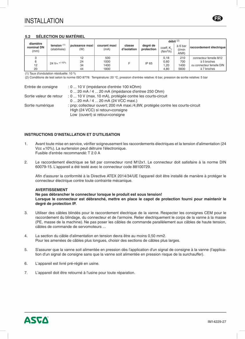
5.2 SÉLECTION DU MATÉRIEL
diamètrenominal DN
(mm)
tension (1)
(stabilisée)puissance maxi
(W)courant maxi
(mA)classe
d'isolationdegré de
protection
débit (2)
raccordement électriquecoeff. KV
(Nm3/h)
à 6 bar(l/min ANR)
361220
24 V= +/-10%
12243444
500 1000 1400 1800
F IP 65
0,180,601,204,80
210 700 1400 5600
connecteur femelle M12 à 5 broches
ou connecteur femelle DIN à 7 broches
(1) Taux d'ondulation résiduelle: 10 %(2) Conditions de test selon la norme ISO 8778: Température: 20 °C, pression d'entrée relative: 6 bar, pression de sortie relative: 5 bar
INSTRUCTIONS D'INSTALLATION ET D'UTILISATION
1. Avant toute mise en service, vérifier soigneusement les raccordements électriques et la tension d'alimentation (24 Vcc ±10%). La surtension peut détruire l'électronique.
Fusible d'entrée recommandé: T 2.0 A
2. Le raccordement électrique se fait par connecteur rond M12x1. Le connecteur doit satisfaire à la norme DIN 60079-15. L'appareil a été testé avec le connecteur code 88100729.
Afin d'assurer la conformité à la Directive ATEX 2014/34/UE l'appareil doit être installé de manière à protéger le connecteur électrique contre toute contrainte mécanique.
AVERTISSEMENT Ne pas débrancher le connecteur lorsque le produit est sous tension! Lorsque le connecteur est débranché, mettre en place le capot de protection fourni pour maintenir le
degré de protection IP.
3. Utiliser des câbles blindés pour le raccordement électrique de la vanne. Respecter les consignes CEM pour le raccordement du blindage, du connecteur et de l'armoire. Relier électriquement le corps de la vanne à la masse (PE, masse de la machine). Ne pas poser les câbles de commande parallèlement aux câbles de haute tension, câbles de commande de servomoteurs ...
4. La section du câble d'alimentation en tension devra être au moins 0,50 mm2. Pour les amenées de câbles plus longues, choisir des sections de câbles plus larges.
5. S'assurer que la vanne soit alimentée en pression dès l'application d'un signal de consigne à la vanne (l'applica-tion d'un signal de consigne sans que la vanne soit alimentée en pression risque de la surchauffer).
6. L'appareil est livré pré-réglé en usine.
7. L'appareil doit être retourné à l'usine pour toute réparation.
INSTALLATION
IM14229-28
FR
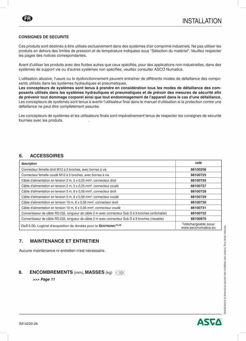
6. ACCESSOIRES
7. MAINTENANCE ET ENTRETIEN
Aucune maintenance ni entretien n'est nécessaire.
description code
Connecteur femelle droit M12 à 5 broches, avec bornes à vis 88100256
Connecteur femelle coudé M12 à 5 broches, avec bornes à vis 88100725
Câble d'alimentation en tension 2 m, 5 x 0,25 mm², connecteur droit 88100726
Câble d'alimentation en tension 2 m, 5 x 0,25 mm², connecteur coudé 88100727
Câble d'alimentation en tension 5 m, 6 x 0,56 mm², connecteur droit 88100728
Câble d'alimentation en tension 5 m, 6 x 0,56 mm², connecteur coudé 88100729
Câble d'alimentation en tension 10 m, 6 x 0,56 mm², connecteur droit 88100730
Câble d'alimentation en tension 10 m, 6 x 0,56 mm², connecteur coudé 88100731
Convertisseur de câble RS-232, longueur de câble 2 m avec connecteur Sub D à 9 broches (enfichable) 88100732
Convertisseur de câble RS-232, longueur de câble 2 m avec connecteur Sub D à 9 broches (vissable) 88100970
DaS 5.00, Logiciel d'acquisition de donées pour la SentronicPLUS Téléchargeable sous: www.asconumatics.eu
CONSIGNES DE SECURITE
Ces produits sont destinés à être utilisés exclusivement dans des systèmes d'air comprimé industriels. Ne pas utiliser les produits en dehors des limites de pression et de température indiquées sous "Sélection du matériel". Veuillez respecter les pages des notices correspondantes.
Avant d'utiliser les produits avec des fluides autres que ceux spécifiés, pour des applications non-industrielles, dans des systèmes de support vie ou d'autres systèmes non spécifiés, veuillez consulter ASCO Numatics.
L'utilisation abusive, l'usure ou le dysfonctionnement peuvent entraîner de différents modes de défaillance des compo-sants utilisés dans les systèmes hydrauliques et pneumatiques.Les concepteurs de systèmes sont tenus à prendre en considération tous les modes de défaillance des com-posants utilisés dans les systèmes hydrauliques et pneumatiques et de prévoir des mesures de sécurité afin de prévenir tout dommage corporel ainsi que tout endommagement de l'appareil dans le cas d'une défaillance.Les concepteurs de systèmes sont tenus à avertir l'utilisateur final dans le manuel d'utilisation si la protection contre une défaillance ne peut être complètement assurée.
Les concepteurs de systèmes et les utilisateurs finals sont impérativement tenus de respecter les consignes de sécurité fournies avec les produits.
7. Wartung und Pflege .............................................................................................................................................38
8. Abmessungen und Gewichte...............................................................................................................................11
ANMERKUNGENDIE IN DIESEM HANDBUCH ENTHALTENEN ANGABEN KÖNNEN OHNE VORHERIGE ANKÜNDIGUNG GEÄNDERT WERDEN.ASCO NUMATICS übernimmt keinerlei Haftung für technische oder redaktionelle Fehler oder Ungenauigkeiten oder für versehentlich entstehende Schäden oder Folgeschäden, die durch die Bereitstellung dieses Handbuchs oder aus der Anwendung desselben entstehen.DAS VORLIEGENDE HANDBUCH ENTHÄLT URHEBERRECHTLICH GESCHÜTZTE ANGABEN. KEIN TEIL DIESES HANDBUCHS DARF OHNE VORHERIGE SCHRIFTLICHE GENEHMIGUNG VON ASCO NUMATICS AUF IRGENDEINE ART UND WEISE VERVIELFÄLTIGT ODER ÜBERTRA-GEN WERDEN.
Dieses Produkt enthält elektronische Bauteile, die gegenüber elektrostati-schen Entladungen (ESD) empfindlich sind. Berührungen der elektrischen Bauteile durch Personen oder Gegenstände können zu einer elektrostati-schen Entladung führen, die das Produkt beschädigt oder zerstört.Um das Risiko einer elektrostatischen Entladung zu vermieden, sind die Handhabungshinweise und Empfehlungen nach EN 100015-1 zu beachten.Zum elektrischen Anschließen oder Trennen des Produkts ist die Versor-gungsspannung abzuschalten.E S D
A C H T U N GVORSICHT BEI HANDHABUNG
VON ELEKTROSTATISCH GEFÄHRDETEN
BAUTEILEN (EGB)
Dieses Produkt entspricht der Richtlinie 2014/30/EU und deren Ergänzungen über die Elektromagnetische Verträglichkeit. Es ist nach CE zugelassen. Eine Konformitätserklärung steht auf Anfrage zur Verfügung.
Geben Sie bitte für die entsprechenden Produkte die Artikelnummer und Seriennummer an.
Hiermit erklären wir, dass das in diesem Installationshandbuch beschriebene Gerät in der von uns gelieferten Ausführung zum Einbau oder Zusam-menbau mit anderen Maschinen bestimmt ist, und dass die Inbetriebnahme so lange untersagt ist, bis festgelegt wurde, dass die Maschine in die das Gerät eingebaut werden soll, den Bestimmungen der Richtlinie 2006/42/EG entspricht.Die Handhabung, Montage und Inbetriebnahme, sowie Einstell- und Justierarbeiten dürfen ausschließlich von autorisiertem Fachpersonal durchgeführt werden.
ACHTUNG! Wenn die Programmierschnittstelle am Ventil benutzt wird, können gefährliche Betriebszustände auftreten, da das Ventil möglicherweise nicht mehr auf den angelegten analogen Sollwert reagiert.Bei Inbetriebnahme und vor Änderungen der Ventileinstellungen sind Vorkehrungen gegen unkontrollierte Bewegung von Anlagenteilen zu treffen.
!
INSTALLATION DE
IM14229-31
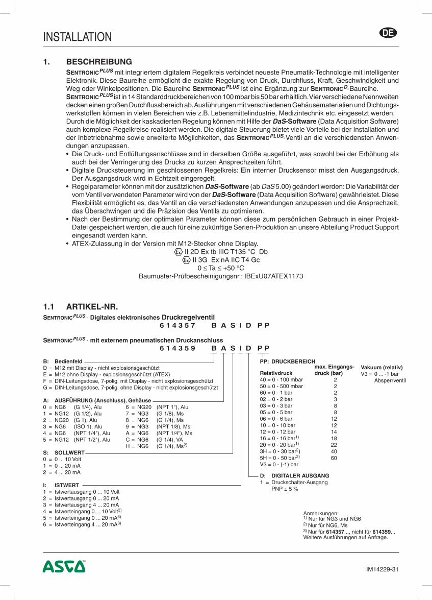
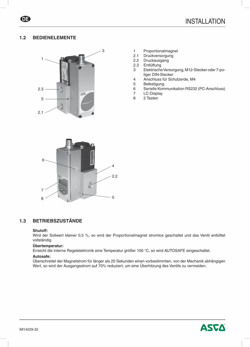
1. BESCHREIBUNGSentronicPLUS mit integriertem digitalem Regelkreis verbindet neueste Pneumatik-Technologie mit intelligenter Elektronik. Diese Baureihe ermöglicht die exakte Regelung von Druck, Durchfluss, Kraft, Geschwindigkeit und Weg oder Winkelpositionen. Die Baureihe SentronicPLUS ist eine Ergänzung zur SentronicD-Baureihe.SentronicPLUS ist in 14 Standarddruckbereichen von 100 mbar bis 50 bar erhältlich. Vier verschiedene Nennweiten decken einen großen Durchflussbereich ab. Ausführungen mit verschiedenen Gehäusematerialien und Dichtungs-werkstoffen können in vielen Bereichen wie z.B. Lebensmittelindustrie, Medizintechnik etc. eingesetzt werden.Durch die Möglichkeit der kaskadierten Regelung können mit Hilfe der DaS-Software (Data Acquisition Software) auch komplexe Regelkreise realisiert werden. Die digitale Steuerung bietet viele Vorteile bei der Installation und der Inbetriebnahme sowie erweiterte Möglichkeiten, das SentronicPLUS-Ventil an die verschiedensten Anwen-dungen anzupassen.• Die Druck- und Entlüftungsanschlüsse sind in derselben Größe ausgeführt, was sowohl bei der Erhöhung als
auch bei der Verringerung des Drucks zu kurzen Ansprechzeiten führt.• Digitale Drucksteuerung im geschlossenen Regelkreis: Ein interner Drucksensor misst den Ausgangsdruck.
Der Ausgangsdruck wird in Echtzeit eingeregelt.• Regelparameter können mit der zusätzlichen DaS-Software (ab DaS 5.00) geändert werden: Die Variabilität der
vom Ventil verwendeten Parameter wird von der DaS-Software (Data Acquisition Software) gewährleistet. Diese Flexibilität ermöglicht es, das Ventil an die verschiedensten Anwendungen anzupassen und die Ansprechzeit, das Überschwingen und die Präzision des Ventils zu optimieren.
• Nach der Bestimmung der optimalen Parameter können diese zum persönlichen Gebrauch in einer Projekt-Datei gespeichert werden, die auch für eine zukünftige Serien-Produktion an unsere Abteilung Product Support eingesandt werden kann.
• ATEX-Zulassung in der Version mit M12-Stecker ohne Display.q II 2D Ex tb IIIC T135 °C Dbq II 3G Ex nA IIC T4 Gc
0 ≤ Ta ≤ +50 °CBaumuster-Prüfbescheinigungsnr.: IBExU07ATEX1173
1.1 ARTIKEL-NR.SentronicPLUS - Digitales elektronisches Druckregelventil 6 1 4 3 5 7 B A S I D P P
SentronicPLUS - mit externem pneumatischen Druckanschluss 6 1 4 3 5 9 B A S I D P P
B: BedienfeldD = M12 mit Display - nicht explosionsgeschütztE = M12 ohne Display - explosionsgeschützt (ATEX)F = DIN-Leitungsdose, 7-polig, mit Display - nicht explosionsgeschütztG = DIN-Leitungsdose, 7-polig, ohne Display - nicht explosionsgeschützt
A: AUSFÜHRUNG (Anschluss), Gehäuse0 = NG6 (G 1/4), Alu 6 = NG20 (NPT 1"), Alu1 = NG12 (G 1/2), Alu 7 = NG3 (G 1/8), Ms2 = NG20 (G 1), Alu 8 = NG6 (G 1/4), Ms3 = NG6 (ISO 1), Alu 9 = NG3 (NPT 1/8), Ms4 = NG6 (NPT 1/4"), Alu A = NG6 (NPT 1/4"), Ms5 = NG12 (NPT 1/2"), Alu C = NG6 (G 1/4), VA H = NG6 (G 1/4), Ms2)
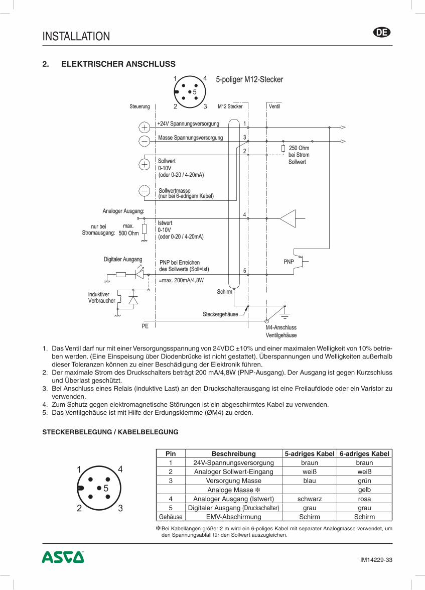
1. Das Ventil darf nur mit einer Versorgungsspannung von 24VDC ±10% und einer maximalen Welligkeit von 10% betrie-ben werden. (Eine Einspeisung über Diodenbrücke ist nicht gestattet). Überspannungen und Welligkeiten außerhalb dieser Toleranzen können zu einer Beschädigung der Elektronik führen.
2. Der maximale Strom des Druckschalters beträgt 200 mA/4,8W (PNP-Ausgang). Der Ausgang ist gegen Kurzschluss und Überlast geschützt.
3. Bei Anschluss eines Relais (induktive Last) an den Druckschalterausgang ist eine Freilaufdiode oder ein Varistor zu verwenden.
4. Zum Schutz gegen elektromagnetische Störungen ist ein abgeschirmtes Kabel zu verwenden.5. Das Ventilgehäuse ist mit Hilfe der Erdungsklemme (ØM4) zu erden.
2. ELEKTRISCHER ANSCHLUSS
STECKERBELEGUNG / KABELBELEGUNG
❉ Bei Kabellängen größer 2 m wird ein 6-poliges Kabel mit separater Analogmasse verwendet, um den Spannungsabfall für den Sollwert auszugleichen.
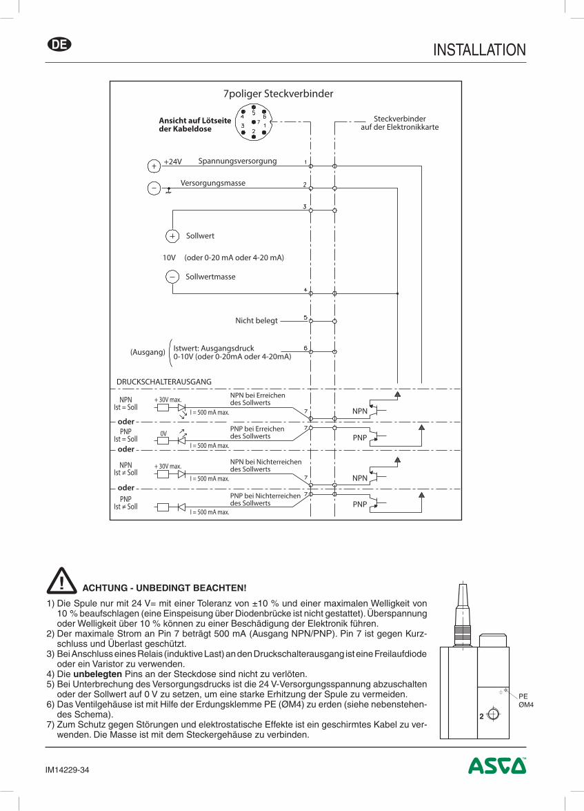
1) Die Spule nur mit 24 V= mit einer Toleranz von ±10 % und einer maximalen Welligkeit von 10 % beaufschlagen (eine Einspeisung über Diodenbrücke ist nicht gestattet). Überspannung oder Welligkeit über 10 % können zu einer Beschädigung der Elektronik führen.
2) Der maximale Strom an Pin 7 beträgt 500 mA (Ausgang NPN/PNP). Pin 7 ist gegen Kurz-schluss und Überlast geschützt.
3) Bei Anschluss eines Relais (induktive Last) an den Druckschalterausgang ist eine Freilaufdiode oder ein Varistor zu verwenden.
4) Die unbelegten Pins an der Steckdose sind nicht zu verlöten.5) Bei Unterbrechung des Versorgungsdrucks ist die 24 V-Versorgungsspannung abzuschalten
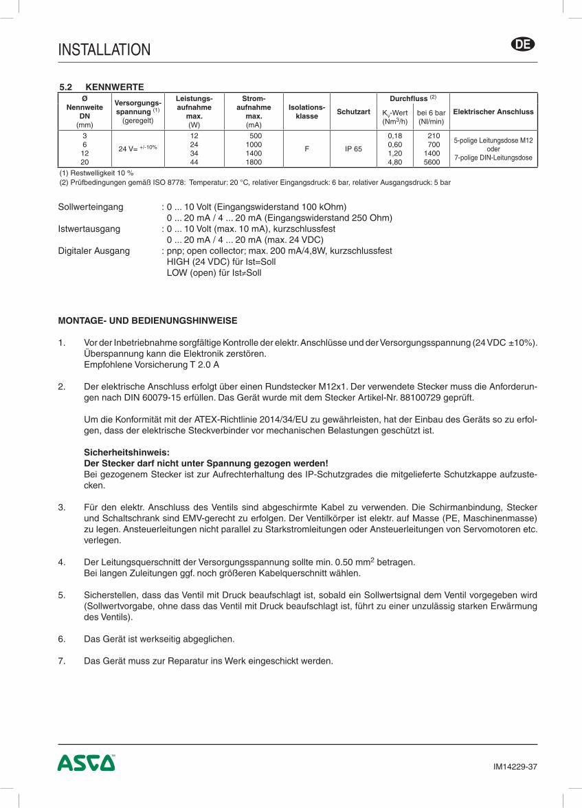
oder der Sollwert auf 0 V zu setzen, um eine starke Erhitzung der Spule zu vermeiden.6) Das Ventilgehäuse ist mit Hilfe der Erdungsklemme PE (ØM4) zu erden (siehe nebenstehen-
des Schema).7) Zum Schutz gegen Störungen und elektrostatische Effekte ist ein geschirmtes Kabel zu ver-
wenden. Die Masse ist mit dem Steckergehäuse zu verbinden.
!
+24V Spannungsversorgung
Versorgungsmasse
Sollwert
10V (oder 0-20 mA oder 4-20 mA)
Sollwertmasse
(Ausgang)
Nicht belegt
Istwert: Ausgangsdruck0-10V (oder 0-20mA oder 4-20mA)
DRUCKSCHALTERAUSGANG
NPN bei Erreichendes Sollwerts
PNP bei Erreichendes Sollwerts
NPN bei Nichterreichendes Sollwerts
PNP bei Nichterreichendes Sollwerts
NPNIst = Soll
+ 30V max.
+ 30V max.
0V
I = 500 mA max.
I = 500 mA max.
I = 500 mA max.
I = 500 mA max.
PNPIst = Soll
NPNIst ≠ Soll
PNPIst ≠ Soll
Steckverbinderauf der Elektronikkarte
NPN
PNP
NPN
PNP
7poliger Steckverbinder
Ansicht auf Lötseiteder Kabeldose
oder
oder
oder
INSTALLATION DE
IM14229-35
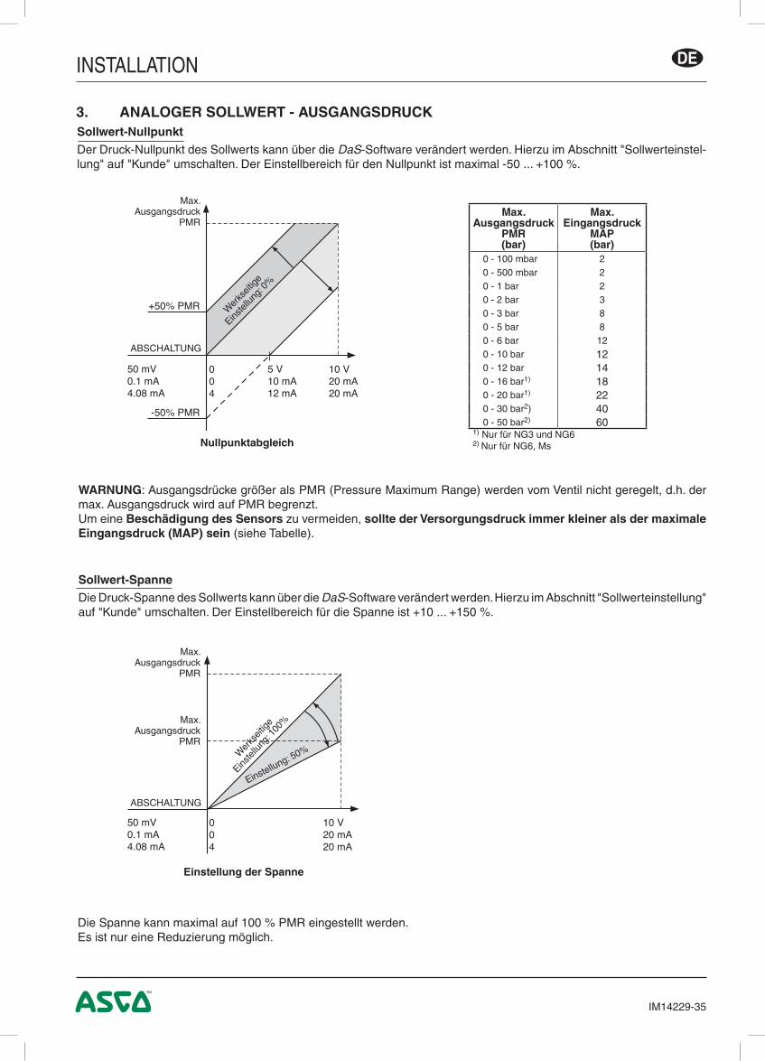
Sollwert-SpanneDie Druck-Spanne des Sollwerts kann über die DaS-Software verändert werden. Hierzu im Abschnitt "Sollwerteinstellung" auf "Kunde" umschalten. Der Einstellbereich für die Spanne ist +10 ... +150 %.
WARNUNG: Ausgangsdrücke größer als PMR (Pressure Maximum Range) werden vom Ventil nicht geregelt, d.h. der max. Ausgangsdruck wird auf PMR begrenzt.Um eine Beschädigung des Sensors zu vermeiden, sollte der Versorgungsdruck immer kleiner als der maximale Eingangsdruck (MAP) sein (siehe Tabelle).
Die Spanne kann maximal auf 100 % PMR eingestellt werden.Es ist nur eine Reduzierung möglich.
3. ANALOGER SOLLWERT - AUSGANGSDRUCKSollwert-NullpunktDer Druck-Nullpunkt des Sollwerts kann über die DaS-Software verändert werden. Hierzu im Abschnitt "Sollwerteinstel-lung" auf "Kunde" umschalten. Der Einstellbereich für den Nullpunkt ist maximal -50 ... +100 %.
Einstellung der Spanne
Nullpunktabgleich
Max. Ausgangsdruck
PMR
ABSCHALTUNG
Max.Ausgangsdruck
PMR(bar)
Max.Eingangsdruck
MAP(bar)
0 - 100 mbar 20 - 500 mbar 20 - 1 bar 20 - 2 bar 30 - 3 bar 80 - 5 bar 80 - 6 bar 120 - 10 bar 120 - 12 bar 140 - 16 bar1) 180 - 20 bar1) 220 - 30 bar2) 400 - 50 bar2) 60
1) Nur für NG3 und NG62) Nur für NG6, Ms
10 V20 mA20 mA
004
5 V10 mA12 mA
50 mV0.1 mA4.08 mA
+50% PMR
-50% PMR
10 V20 mA20 mA
004
50 mV0.1 mA4.08 mA
Wer
kseit
ige
Einstel
lung:
0%
Max. Ausgangsdruck
PMR
ABSCHALTUNG
Max. Ausgangsdruck
PMR
Wer
kseit
ige
Einste
llung
: 100
%
Einstellung: 50%
INSTALLATIONDE
IM14229-36
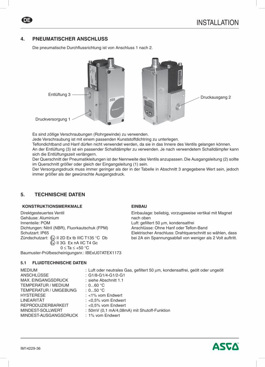
4. PNEUMATISCHER ANSCHLUSS
Die pneumatische Durchflussrichtung ist von Anschluss 1 nach 2.
Es sind zöllige Verschraubungen (Rohrgewinde) zu verwenden.Jede Verschraubung ist mit einem passenden Kunststoffdichtring zu unterlegen.Teflondichtband und Hanf dürfen nicht verwendet werden, da sie in das Innere des Ventils gelangen können.An der Entlüftung (3) ist ein passender Schalldämpfer zu verwenden. Je nach verwendetem Schalldämpfer kann sich die Entlüftungszeit verlängern.Der Querschnitt der Pneumatikleitungen ist der Nennweite des Ventils anzupassen. Die Ausgangsleitung (2) sollte im Querschnitt größer oder gleich der Eingangsleitung (1) sein. Der Versorgungsdruck muss immer geringer als der in der Tabelle in Abschnitt 3 angegebene Wert sein, jedoch immer größer als der gewünschte Ausgangsdruck.
5. TECHNISCHE DATEN
KONSTRUKTIONSMERKMALE EINBAU
Direktgesteuertes VentilGehäuse: AluminiumInnenteile: POMDichtungen: Nitril (NBR), Fluorkautschuk (FPM)Schutzart: IP65Zündschutzart: q II 2D Ex tb IIIC T135 °C Db q II 3G Ex nA IIC T4 Gc 0 ≤ Ta ≤ +50 °CBaumuster-Prüfbescheinigungsnr.: IBExU07ATEX1173
Einbaulage: beliebig, vorzugsweise vertikal mit Magnet nach obenLuft: gefiltert 50 µm, kondensatfreiAnschlüsse: Ohne Hanf oder Teflon-BandElektrischer Anschluss: Drahtquerschnitt so wählen, dass bei 2A ein Spannungsabfall von weniger als 2 Volt auftritt.
5.1 FLUIDTECHNISCHE DATEN
MEDIUM : Luft oder neutrales Gas, gefiltert 50 µm, kondensatfrei, geölt oder ungeöltANSCHLÜSSE : G1/8-G1/4-G1/2-G1MAX. EINGANGSDRUCK : siehe Abschnitt 1.1TEMPERATUR / MEDIUM : 0...60 °CTEMPERATUR / UMGEBUNG : 0...50 °CHYSTERESE : <1% vom EndwertLINEARITÄT : <0,5% vom EndwertREPRODUZIERBARKEIT : <0,5% vom EndwertMINDEST-SOLLWERT : 50mV (0,1 mA/4,08mA) mit Shutoff-FunktionMINDEST-AUSGANGSDRUCK : 1% vom Endwert
Druckversorgung 1
Entlüftung 3Druckausgang 2
INSTALLATION DE
IM14229-37
Sollwerteingang : 0 ... 10 Volt (Eingangswiderstand 100 kOhm) 0 ... 20 mA / 4 ... 20 mA (Eingangswiderstand 250 Ohm)Istwertausgang : 0 ... 10 Volt (max. 10 mA), kurzschlussfest 0 ... 20 mA / 4 ... 20 mA (max. 24 VDC)Digitaler Ausgang : pnp; open collector; max. 200 mA/4,8W, kurzschlussfest HIGH (24 VDC) für Ist=Soll LOW (open) für Ist≠Soll
5.2 KENNWERTEØ
Nennweite DN
(mm)
Versorgungs-spannung (1)
(geregelt)
Leistungs- aufnahme
max.(W)
Strom- aufnahme
max.(mA)
Isolations-klasse
Schutzart
Durchfluss (2)
Elektrischer AnschlussKV-Wert(Nm3/h)
bei 6 bar(Nl/min)
361220
24 V= +/-10%
12243444
500 1000 1400 1800
F IP 65
0,180,601,204,80
210 700 1400 5600
5-polige Leitungsdose M12oder
7-polige DIN-Leitungsdose
(1) Restwelligkeit 10 %(2) Prüfbedingungen gemäß ISO 8778: Temperatur: 20 °C, relativer Eingangsdruck: 6 bar, relativer Ausgangsdruck: 5 bar
MONTAGE- UND BEDIENUNGSHINWEISE
1. Vor der Inbetriebnahme sorgfältige Kontrolle der elektr. Anschlüsse und der Versorgungsspannung (24 VDC ±10%). Überspannung kann die Elektronik zerstören.
Empfohlene Vorsicherung T 2.0 A
2. Der elektrische Anschluss erfolgt über einen Rundstecker M12x1. Der verwendete Stecker muss die Anforderun-gen nach DIN 60079-15 erfüllen. Das Gerät wurde mit dem Stecker Artikel-Nr. 88100729 geprüft.
Um die Konformität mit der ATEX-Richtlinie 2014/34/EU zu gewährleisten, hat der Einbau des Geräts so zu erfol-gen, dass der elektrische Steckverbinder vor mechanischen Belastungen geschützt ist.
Sicherheitshinweis: Der Stecker darf nicht unter Spannung gezogen werden! Bei gezogenem Stecker ist zur Aufrechterhaltung des IP-Schutzgrades die mitgelieferte Schutzkappe aufzuste-
cken.
3. Für den elektr. Anschluss des Ventils sind abgeschirmte Kabel zu verwenden. Die Schirmanbindung, Stecker und Schaltschrank sind EMV-gerecht zu erfolgen. Der Ventilkörper ist elektr. auf Masse (PE, Maschinenmasse) zu legen. Ansteuerleitungen nicht parallel zu Starkstromleitungen oder Ansteuerleitungen von Servomotoren etc. verlegen.
4. Der Leitungsquerschnitt der Versorgungsspannung sollte min. 0.50 mm2 betragen. Bei langen Zuleitungen ggf. noch größeren Kabelquerschnitt wählen.
5. Sicherstellen, dass das Ventil mit Druck beaufschlagt ist, sobald ein Sollwertsignal dem Ventil vorgegeben wird (Sollwertvorgabe, ohne dass das Ventil mit Druck beaufschlagt ist, führt zu einer unzulässig starken Erwärmung des Ventils).
6. Das Gerät ist werkseitig abgeglichen.
7. Das Gerät muss zur Reparatur ins Werk eingeschickt werden.
INSTALLATIONDE
IM14229-38
8. ABMESSUNGEN (mm), GEWICHTE (kg)
>>> Siehe Seite 11
6. ZUBEHÖR
7. WARTUNG UND PFLEGE
Keine besonderen Anforderungen.
Beschreibung Artikel-Nr.
Gerade M12 Leitungsdose, 5-polig, mit Schraubklemmen 88100256
M12 Winkel-Leitungsdose, 5-polig, mit Schraubklemmen 88100725
Spannungsversorgungskabel 2 m, 5x0,25 mm², gerade Leitungsdose 88100726
Spannungsversorgungskabel 2 m, 5x0,25 mm², Winkel-Leitungsdose 88100727
Spannungsversorgungskabel 5 m, 6x0,56 mm², gerade Leitungsdose 88100728
Spannungsversorgungskabel 5 m, 6x0,56 mm², Winkel-Leitungsdose 88100729
Spannungsversorgungskabel 10 m, 6x0,56 mm², gerade Leitungsdose 88100730
Spannungsversorgungskabel 10 m, 6x0,56 mm², Winkel-Leitungsdose 88100731
RS-232-Umsetzer, 2 m Kabel mit 9-poligem Sub-D-Stecker (steckbar) 88100732
RS-232-Umsetzer, 2 m Kabel mit 9-poligem Sub-D-Stecker (schraubbar) 88100970
DaS 5.00, Data Acquisition Software für SentronicPLUS Herunterladbar unter: www.asconumatics.de
SICHERHEITSHINWEISE
Diese Produkte sind ausschließlich in industriellen Druckluftsystemen zu verwenden. Sie sind dort einzusetzen, wo die unter "Spezifikationen" aufgeführten Druck- und Temperaturwerte nicht überschritten werden. Berücksichtigen Sie bitte die entsprechende Druckschriftenseite.
Vor dem Einsatz der Produkte mit Flüssigkeiten sowie bei nicht industriellen Anwendungen, in lebenserhaltenden- oder anderen Systemen, die nicht in den veröffentlichten Anleitungsunterlagen enthalten sind, wenden Sie sich bitte direkt an ASCO Numatics.
Durch Missbrauch, Verschleiß oder Störungen können in Hydrosystemen verwendete Komponenten auf verschiedene Arten versagen.Systemauslegern wird dringend empfohlen, die Störungsarten aller in Hydrosystemen verwendeten Kompo-nententeile zu berücksichtigen und ausreichende Sicherheitsvorkehrungen zu treffen, um Verletzungen von Personen sowie Beschädigungen der Geräte im Falle einer solchen Störung zu verhindern.Systemausleger sind verpflichtet, Sicherheitshinweise für den Endbenutzer im Betriebshandbuch zu vermerken, wenn der Störungsschutz nicht ausreichend gewährleistet ist.
Systemauslegern und Endbenutzern wird dringend empfohlen, die den Produkten beiliegenden Sicherheitsvorschriften einzuhalten.