51
Series 90 Axial Piston Pumps Technical Information

Series 90 Axial Piston Pumps
Technical Information
2 520L0603
Series 90 Axial Piston PumpsTechnical Information
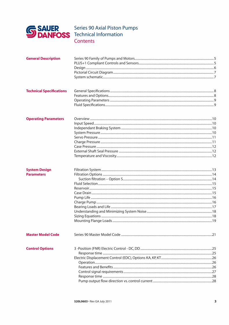
Table of RevisionsDate Page Changed Rev.
all Major update
last new back page FF
Various Fix O-ring dimensions in dimension drawings FE
Various FD
FC
Various Minor edits and dimension changes FB
- F
History of Revisions
3520L0603
Series 90 Axial Piston PumpsTechnical InformationContents
General Description
Technical Specifications
Operating Parameters
System Design Parameters
Master Model Code
Control Options
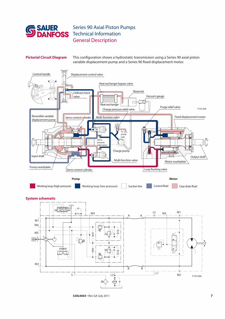
DesignPictorial Circuit Diagram
Features and OptionsOperating Parameters 9Fluid Specifications 9
Input Speed
Charge PressureCase PressureExternal Shaft Seal Pressure
Filtration OptionsSuction filtration – Option S
Fluid Selection
Case Drain
Charge Pump
Series 90 Master Model Code
OperationFeatures and Benefits
4 520L0603
Series 90 Axial Piston PumpsTechnical InformationContents
Control Options (continued)
Installation Drawings
Features and Options
Operation
Operation
Pressure limiting function
4040
Charge Pump
Speed Sensor 44Connector Pin Assignments
49
Integral Pressure Filter
5520L0603
Series 90 Axial Piston PumpsTechnical Information
Series 90 variable displacement pumps
Series 90 motors
Series 90 Motors Technical Information 520L0604
Series 90 pumps can be used together in combination with other Sauer-Danfoss pumps
Series 90 Family of Pumps and Motors
PLUS+1 Compliant Controls and Sensors

6 520L0603
Series 90 Axial Piston PumpsTechnical Information
P106 648E
Slider block
Servo piston
Servo armDisplacement control
Cradle bearing
Charge pump Swashplate Cradle guide
Feedback linkage
Roller bearing
Shaft
PistonSlipper
Valve plate
Cylinder block
Input shaft
Rear
bushing
Bushing
seal
Design Series 90 pump cross-section
Typical name plate
Model-No./Ident-No.
Model Code
Serial-No.
Made in USA
Place of Manufacture
ModelNumber
SerialNumber
ModelCode
A - 88 - 126 - 67890
501829
P108 494E
90L055 KA 1 N 6 S 3 C6 C 03 NNN 35 35 24
7520L0603
Series 90 Axial Piston PumpsTechnical Information
Pump Motor
Working loop (low pressure) Control fluidSuction line Case drain fluidWorking loop (high pressure)
Motor swashplate
Loop flushing valve
Displacement control valve
Heat exchanger bypass valve
Reservoir
Vacuum gauge
Purge relief valve
Fixed displacement motor
Output shaftMulti-function valve
Charge pump
To pump case
Servo pressurerelief valves
Servo control cylinderPump swashplate
Input shaft
Reversible variabledisplacement pump
Servo control cylinder
Heat exchanger
Multi-function valve
Charge pressure relief valve
Orificed checkvalve
Control handle
P102 000
Pictorial Circuit Diagram
M
BB
L2
M2
M1
M4
M5
M3A A
S
L2 M1
M2L1
M3
P104 286E
System schematic
8 520L0603
Series 90 Axial Piston PumpsTechnical InformationTechnical Specifications
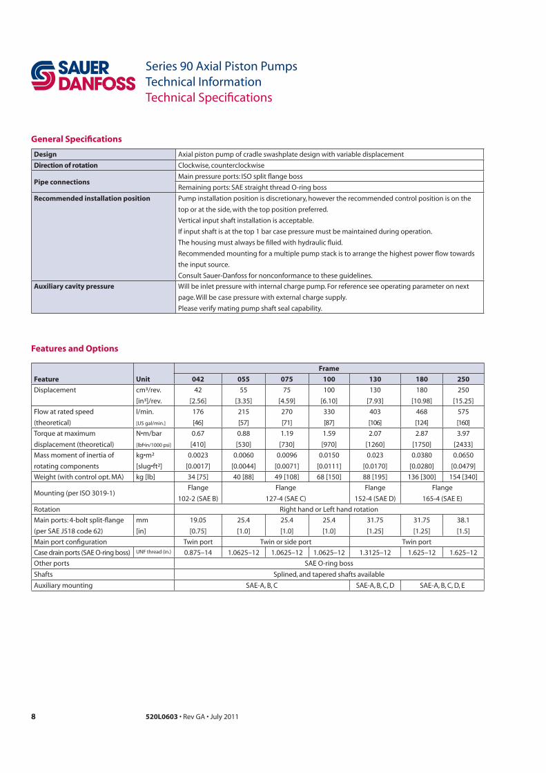
Feature Unit
Frame
042 055 075 100 130 180 250
Displacement
Flow at rated speed
Mass moment of inertia of
rotating components
kg [lb]
Flange Flange Flange Flange
mm
[in]
Main port configuration Twin port Twin or side port Twin port
Other ports SAE O-ring boss
Shafts
Features and Options
General Specifications
Design
Direction of rotation
Pipe connections
Recommended installation position
Auxiliary cavity pressure
9520L0603
Series 90 Axial Piston PumpsTechnical InformationTechnical Specifications
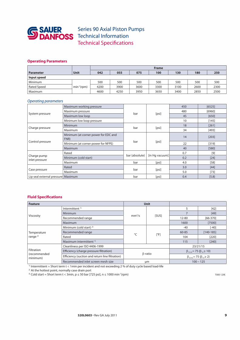
Operating Parameters
Parameter Unit
Frame
042 055 075 100 130 180 250
Input speed
Minimum
min
Maximum
Fluid Specifications
Feature UnitIntermittent 1)
mm2/s [SUS]
5 [42]Minimum 7 [49]Recommended range 12-80 [66-370]Maximum
Temperaturerange
Minimum (cold start) 3)
°C [°F]
-40 [-40]Recommended rangeRated 104 [220]Maximum intermittent 1)
Filtration Cleanliness per ISO 4406-1999 23/21/15Efficiency (charge pressure filtration)
-ratio15-20 = 75 ( 10 ≥ 10)
Efficiency (suction and return line filtration) 35-45 = 75 ( 10 ≥ 2)
Recommended inlet screen mesh size µm 100 – 1251) Intermittent = Short term t < 1min per incident and not exceeding 2 % of duty cycle based load-life2) At the hottest point, normally case drain port3) Cold start = Short term t < 3min, p ≤ 50 bar [725 psi], n ≤ 1000 min-1(rpm) T000 129E
Operating parameters
System pressure
Maximum working pressure
bar [psi]
450Maximum pressure 480Maximum low loop 45 [650]Minimum low loop pressure 10 [145]
Charge pressureMinimum
bar [psi]18 [261]
Maximum 34 [493]
Control pressure
Minimum (at corner power for EDC and FNR)
bar [psi]14 [203]
Minimum (at corner power for NFPE) 22 [319]Maximum 40 [580]
Charge pump inlet pressure
Ratedbar (absolute) [in Hg vacuum]
0.7 [9]Minimum (cold start) 0.2 [24]Maximum bar [psi] 4.0 [58]
Case pressureRated
bar [psi]3.0 [44]
Maximum 5.0 [73]Lip seal external pressure Maximum bar [psi] 0.4 [5.8}

10 520L0603
Series 90 Axial Piston PumpsTechnical InformationOperating Parameters
Input Speed
System Pressure
This section defines the operating parameters and limitations for Series 90 pumps with
Minimum speed
Rated speed
Maximum speed
For more information consult Pressure and Speed Limits BLN-9884
Unintended vehicle or machine movement hazard
System pressure
Application pressure
Maximum working pressure
Overview
Independant Braking System
11520L0603
Series 90 Axial Piston PumpsTechnical InformationOperating Parameters
Servo Pressure
Charge Pressure
Maximum pressure
Minimum low loop pressure must be maintained under all operating conditions to
At minimum
Minimum
Maximum
control with pressure to operate the swashplate and to maintain a minimum pressure in
Minimum charge pressure is the lowest pressure allowed to maintain a safe working
Maximum charge pressure
At normal operating temperature charge inlet pressure must not fall below rated charge inlet pressure (vacuum)
Minimum charge inlet pressure
Maximum charge pump inlet pressure
System Pressure(continued)

12 520L0603
Series 90 Axial Piston PumpsTechnical InformationOperating Parameters
Case Pressure
External Shaft Seal Pressure
Temperature and Viscosity
rated case pressureDuring cold start case pressure must be kept below maximum intermittent case
Auxiliary Pad Mounted Pumps
CautionPossible component damage or leakage
Caution
Temperature
rated temperature
The maximum intermittent temperature is based on material properties and should
The minimum temperature
Viscosity
recommended range
The minimum viscosity
The maximum viscosity
13520L0603
Series 90 Axial Piston PumpsTechnical Information
Filtration System
X
with a -ratio within the range of ≥
-ratio in the range of ≥
Design Guidelines for Hydraulic Fluid Cleanliness Technical Information 520L0467
Filter x

14 520L0603
Series 90 Axial Piston PumpsTechnical Information
Filtration Options Suction filtration – Option SThe suction filter is placed in the circuit
The use of a filter contamination monitor
Charge pumpFilter
Hydraulic fluid reservoir
Adjustable charge pressure relief valve
To pump case
To low loop andcontrol
Manometer
P102 003E
Suction filtration
Charge pressure filtration (partial charge pump flow)
In either case the filtration circuit is the same with the filter element situated in the
Charge pressure filtration
To pump case
Charge pump
Hydraulic fluid reservoir
FilterTo low pressure side andcontrol
Screen
Adjustable charge pressure relief valve
P102 004E
Caution
pressure drops that can lead to charge pump damage in addition to contaminants being
Remote charge pressure filtration
allow for the charge filter to be located
Ensure the normal operating pressure drop across the remote filtration in and
pressure setting of the recommended
Nominal flow at 30mm2/s and P 0.5 bar[7.3 psi] (clean filter element only) Minimum -ratio
Short 60 l/min7.5(C)=75 ( 5(C) 10)
Long 105 l/min
Technical data according to ISO 16889
Caution

15520L0603
Series 90 Axial Piston PumpsTechnical Information
Hydraulic Fluids and Lubricants Technical Information 520L0463Experience with Biodegradable Hydraulic Fluids Technical Information 520L0465
A case drain line must be connected to one of the case outlets to return internal leakage
Fluid Selection
Reservoir
Case Drain

16 520L0603
Series 90 Axial Piston PumpsTechnical Information
Charge Pump
Charge pump sizing/selectionIn most applications a general guideline is that the charge pump displacement should
Selection of Drive line Components BLN-9885
Pump Life

17520L0603
Series 90 Axial Piston PumpsTechnical Information
Bearing Loads and Life
Maximum allowable external shaft loadParameter 042 055 075 100 130 180 250
* *
Applications with external shaft loads
Re = Me / L
B
A
P108 549E
0°Re
90°Re
270°Re
180°Re
L
Re
Radial load positionMe = Shaft momentL = Flange distanceRe = External force

18 520L0603
Series 90 Axial Piston PumpsTechnical Information
Understanding and Minimizing System Noise
Fluid-borne noise
Structure born noise
Follow these suggestions to help minimize noise in your application:
Output flow Q =
Input power P = =
SI units Vg
p = pO - pi
m
t m
Vg
Vg p
m
p
t
US units Vg
p = pO - pi
m
t m
Output flow Q =
Input power P = =
Vg
Vg p
m
p
t
Sizing Equations
Selection of drive line components BLN-9885
19520L0603
Series 90 Axial Piston PumpsTechnical Information
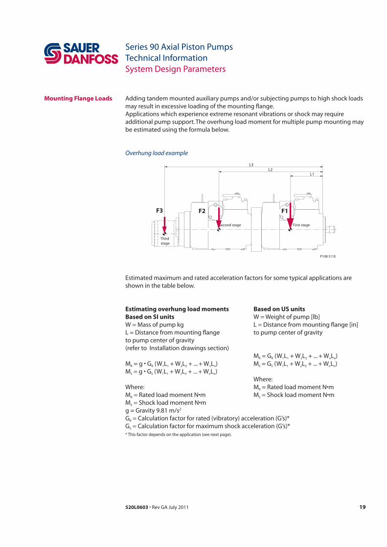
Mounting Flange Loads
Estimating overhung load moments Based on SI units
M n n
MS S n n
MMS
S
M n n
MS S n n
Based on US units
MMS
First stageSecond stage
Third stage
P108 511E
L1L2
L3
F2 F1F3
Overhung load example
20 520L0603
Series 90 Axial Piston PumpsTechnical Information
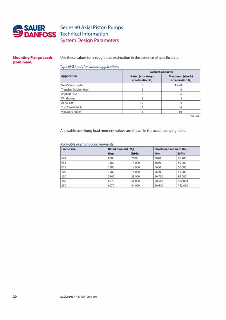
Mounting Flange Loads(continued)
Typical G loads for various applications
ApplicationCalculation factor
Rated (vibratory)acceleration GR
Maximum (shock) acceleration GS
Skid Steer Loader 8 15-20Trencher (rubber tires) 3 8Asphalt Paver 2 6Windrower 2 5Aerial Lift 1.5 4Turf Care Vehicle 1.5 4Vibratory Roller 6 10
T000 165E
Allowable overhung load momentsFrame size Rated moment (MR) Shock load moment (MS)
21520L0603
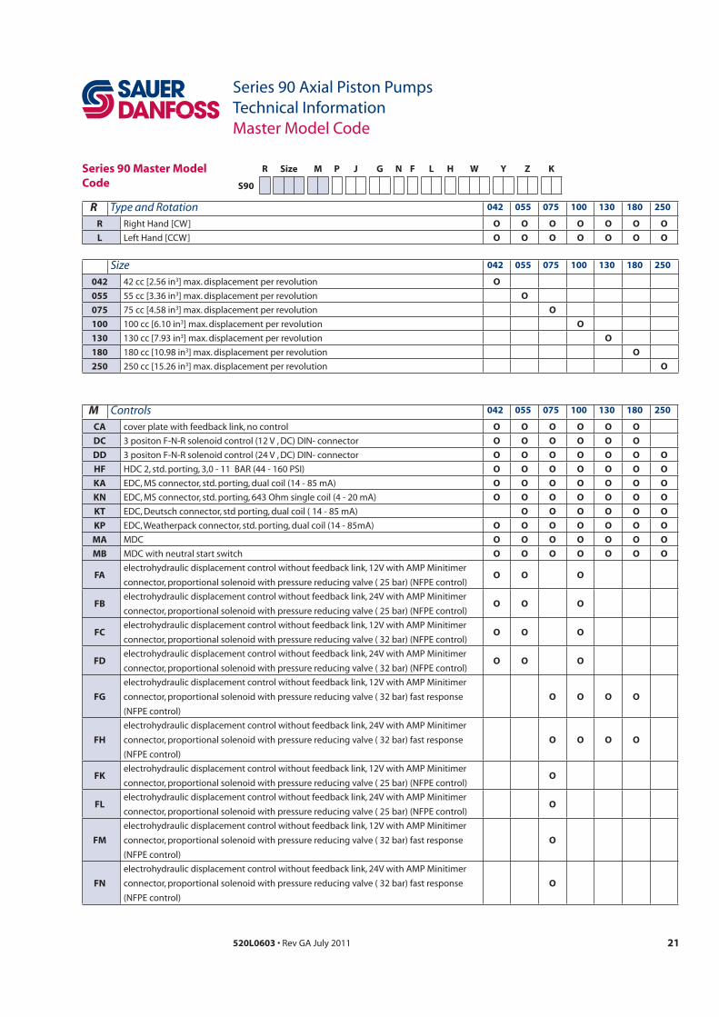
Series 90 Axial Piston PumpsTechnical InformationMaster Model Code
R Size M P J G N F L H W Y Z K
S90
Size 042 055 075 100 130 180 250
042 O
055 O
075 O
100 O
130 O
180 O
250 O
R Type and Rotation 042 055 075 100 130 180 250
R O O O O O O O
L O O O O O O O
M Controls 042 055 075 100 130 180 250
CA O O O O O O
DC O O O O O O
DD O O O O O O O
HF O O O O O O O
KA O O O O O O O
KN O O O O O O O
KT O O O O O O
KP O O O O O O O
MA MDC O O O O O O O
MB MDC with neutral start switch O O O O O O O
FA O O O
FB O O O
FC O O O
FD O O O
FG O O O O
FH O O O O
FK O
FL O
FM O
FN O
Series 90 Master Model Code

22 520L0603
Series 90 Axial Piston PumpsTechnical InformationMaster Model Code
P High Pressure Regulation 042 055 075 100 130 180 250
1 O O O O O O O
2 O O O O O O O
R Size M P J G N F L H W Y Z K
S90
J Auxiliary Mounting Pad 042 055 075 100 130 180 250
AB O O O O O O O
BB O O O O O O O
BC O O O O O O O
CD O O O O O O
DE O O O
EF O O
NN O O O O O O O
G Endcap Ports 042 055 075 100 130 180 250
60 Side Ports O O O
80 Twin Ports O O O O O O O
N Filtration 042 055 075 100 130 180 250
D external charge pump O O O O O O
L O O O O O
P O O O O O
R remote pressure O O O O
T O O
S suction filtration O O O O O O O
F Displacement Limitation 042 055 075 100 130 180 250
C O
M O
3 no limiters O O O O O O
4 limitation both sides O O O O O O
7 O O O O O O
Series 90 Master Model Code (continued)
23520L0603
Series 90 Axial Piston PumpsTechnical InformationMaster Model Code
R Size M P J G N F L H W Y Z K
S90
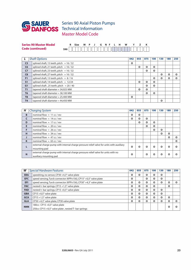
W Special Hardware Features 042 055 075 100 130 180 250
EEG O O O O O
EFC O O O O
EFI O O O O O O O
FAC O O O O O
FAD O O O O O
GBA O O O O O
GCA O O O O O O
GLA O O O O O O O
NNN O O
Series 90 Master Model Code (continued)
L Shaft Options 042 055 075 100 130 180 250
C3 O
C6 O O O
C7 O O
C8 O O O
F1 O O O O
S1 O O O
G1 O O
T1 O O
T6 O O
T8 O
T4 O
H Charging System 042 055 075 100 130 180 250
B O O
C O O O
D O O O
E O O
F O O
H O O
J O O
K O
Lmounting pad
O O O O O O O
N O O O O O O

24 520L0603
Series 90 Axial Piston PumpsTechnical InformationMaster Model Code
Y High Pressure Setting A 042 055 075 100 130 180 250
26 O O O O O O O
32 O O O O O O O
35 O O O O O O O
38 O O O O O O O
40 400 bar O O O O O O O
42 O O O O O O O
Z High Pressure Setting B 042 055 075 100 130 180 250
26 O O O O O O O
32 O O O O O O O
35 O O O O O O O
38 O O O O O O O
40 400 bar O O O O O O O
42 O O O O O O O
R Size M P J G N F L H W Y Z K
S90
Series 90 Master Model Code (continued)
K Charge Pressure Setting 042 055 075 100 130 180 250
20 O O O O O O O
22 O O O O O O O
24 O O O O O O O
26 O O O O O O O
28 O O O O O O O
30 O O O O O O O
32 O O O O O O
34 O O O O O
25520L0603
Series 90 Axial Piston PumpsTechnical InformationControl Options
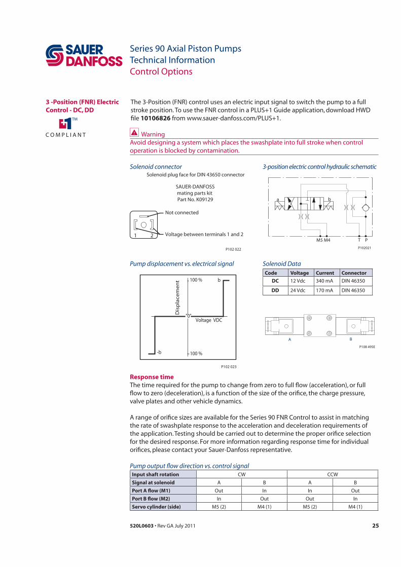
3 -Position (FNR) Electric Control - DC, DD
file 10106826
1 2
Not connected
Voltage between terminals 1 and 2
SAUER-DANFOSSmating parts kit Part No. K09129
Solenoid plug face for DIN 43650 connector
P102 022
Solenoid connector
M5
a b
M4 T P
P102021
3-position electric control hydraulic schematic
"0"Voltage VDC
Dis
pla
cem
en
t 100 % b
100 %-b
P102 023
Pump displacement vs. electrical signal Solenoid DataCode Voltage Current Connector
DC
DD
Response time
Pump output flow direction vs. control signalInput shaft rotation
Signal at solenoid A B A B
Port A flow (M1) Out In In Out
Port B flow (M2) In Out Out In
Servo cylinder (side)
A
P108 495E
B
26 520L0603
Series 90 Axial Piston PumpsTechnical InformationControl Options
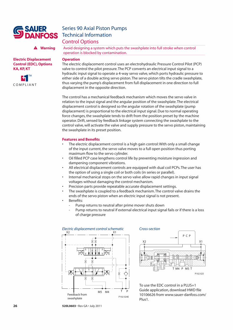
Electric Displacement Control (EDC), Options KA, KP, KT
Operation
Features and Benefits
- Pump returns to neutral if external electrical input signal fails or if there is a loss of charge pressure
T P TM4 M5
P C P
X2 X1
P102 025
Cross-sectionElectric displacement control schematic
M5 M4 T P
X2 X1
P102 024EFeedback fromswashplate
Warning
27520L0603
Series 90 Axial Piston PumpsTechnical InformationControl Options
Electric Displacement Control (EDC)(continued)
Pump displacement vs. control current
"0"Current mA
Dis
pla
cem
en
t100 %
a b
-b -a
100 %P102 026E
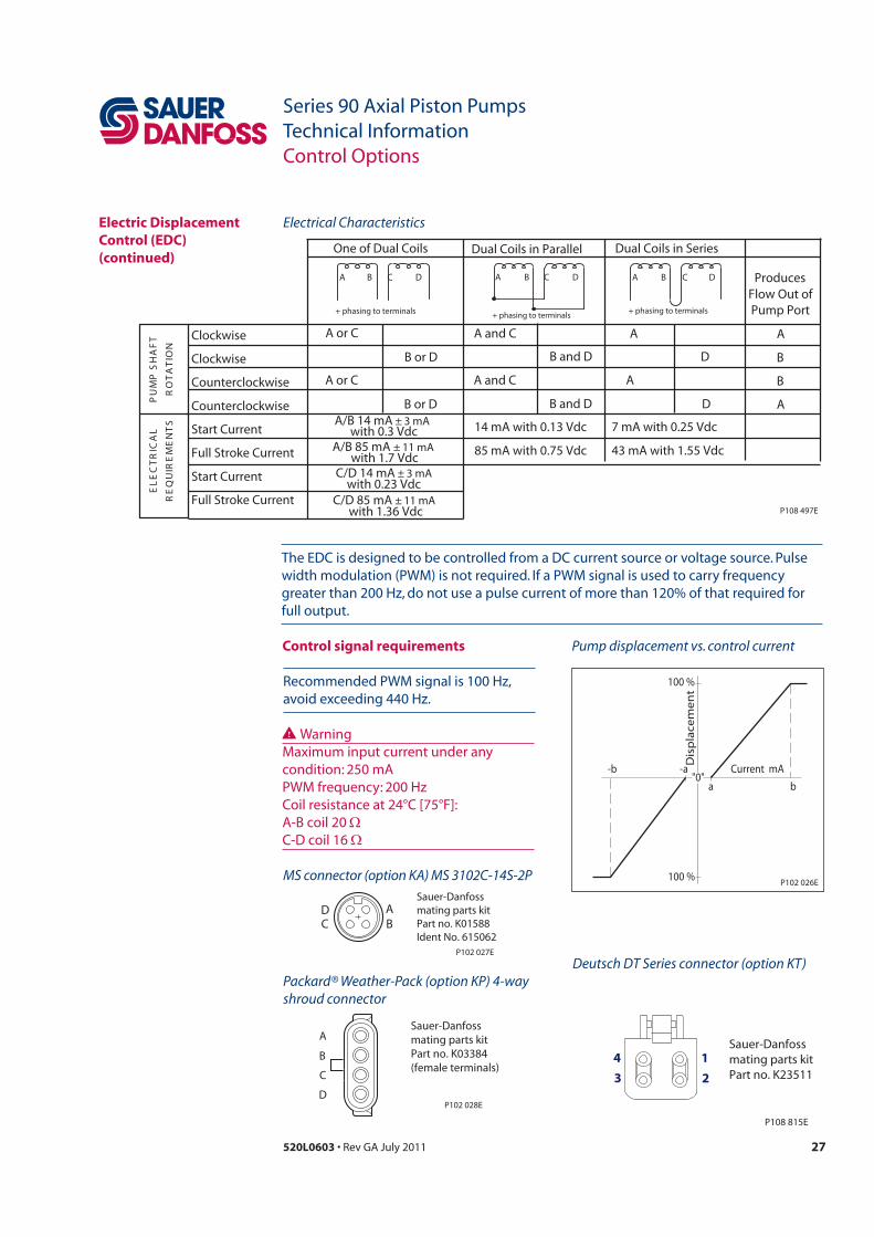
MS connector (option KA) MS 3102C-14S-2P
AB
DC
Sauer-Danfossmating parts kit Part no. K01588Ident No. 615062
P102 027E
Packard® Weather-Pack (option KP) 4-way shroud connector
B
C
D
Sauer-Danfossmating parts kit Part no. K03384(female terminals)
A
P102 028E
Control signal requirements
7 mA with 0.25 Vdc
43 mA with 1.55 Vdc
Clockwise
Clockwise
Counterclockwise
Counterclockwise
Start Current
Full Stroke Current
Start Current
Full Stroke Current
TF
AH
S P
MU
P
NOI
TA
TO
R
LA
CIR
TC
EL
E
ST
NE
ME
RIU
QE
R
A or C
B or D
A and C A
D
One of Dual Coils Dual Coils in Parallel Dual Coils in Series
A
B
B
A
ProducesFlow Out ofPump Port
A or C A and C A
B or D B and D D
B and D
14 mA with 0.13 Vdc
85 mA with 0.75 Vdc
A B C D
+ phasing to terminals
B C DA
+ phasing to terminals
B C DA
+ phasing to terminals
A/B 14 mA ± 3 mA
A/B 85 mA ± 11 mA
C/D 14 mA ± 3 mA
C/D 85 mA ± 11 mAP108 497E
with 1.7 Vdc
with 0.3 Vdc
with 0.23 Vdc
with 1.36 Vdc
Electrical Characteristics
Warning
Deutsch DT Series connector (option KT)
13 24
P108 815E
Sauer-Danfossmating parts kit Part no. K23511
28 520L0603
Series 90 Axial Piston PumpsTechnical InformationControl Options
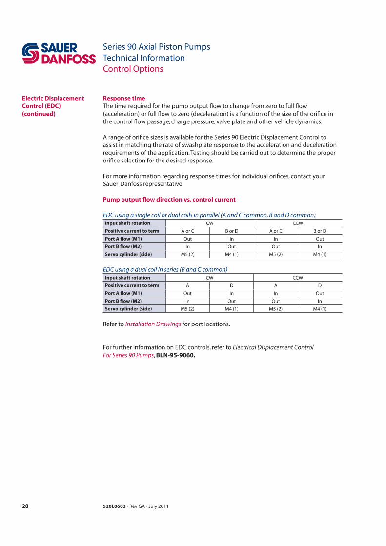
Response time
assist in matching the rate of swashplate response to the acceleration and deceleration
Pump output flow direction vs. control current
EDC using a single coil or dual coils in parallel (A and C common, B and D common)Input shaft rotation
Positive current to term A or C B or D A or C B or D
Port A flow (M1) Out In In Out
Port B flow (M2) In Out Out In
Servo cylinder (side)
EDC using a dual coil in series (B and C common)Input shaft rotation
Positive current to term A D A D
Port A flow (M1) Out In In Out
Port B flow (M2) In Out Out In
Servo cylinder (side)
Installation Drawings
Electric Displacement Control (EDC)(continued)
Electrical Displacement ControlFor Series 90 Pumps BLN-95-9060.

29520L0603
Series 90 Axial Piston PumpsTechnical InformationControl Options
Manual Over Ride (MOR)
Warning
Warning
P108 496EEDC Second Stage
Manual Over Ride (MOR)
EDC Pilot Stage (PCP)
Pump Phasing With EDC Manual Operator (MOR)
Pump MORRotation
Pump FlowtroP tuOnoitatoR
CW Towards ConnectorTowards Connector
BAWCC
P108 498E
Warning

30 520L0603
Series 90 Axial Piston PumpsTechnical InformationControl Options
Hydraulic Displacement Control (HDC) , Option HF
Warning
Operation
Features and benefits of the hydraulic displacement control:
- Pump returns to neutral if there is a loss of input signal pressure or if there is a
M5 M4 T P
Feedbackfromswashplate
X2 X1
P102029
Hydraulic displacement control schematic
T M4 P M5 T
P102 030
X1 X2
Cross-section

31520L0603
Series 90 Axial Piston PumpsTechnical InformationControl Options
Response time
control to assist in matching the rate of swashplate response to the acceleration
to determine the proper orifice selection
For more information regarding
Pump output flow direction vs. control pressureInput shaft rotation
Control pressure to
port
Port A flow (M1) Out In In Out
Port B flow (M2) In Out Out In
Servo cylinder (side)
Installation drawings
Hydraulic Displacement Control (HDC)(continued)
Pump displacement vs. signal pressure
"0"Signal pressure
Dis
pla
cem
en
t
100 %
a b
-b -a
100 % P102 031E
WarningControl signal requirements
Exceeding allowable signal
Hydraulic signal pressure range*a
b
32 520L0603
Series 90 Axial Piston PumpsTechnical InformationControl Options
Manual Displacement Control (MDC), Options MA, MB
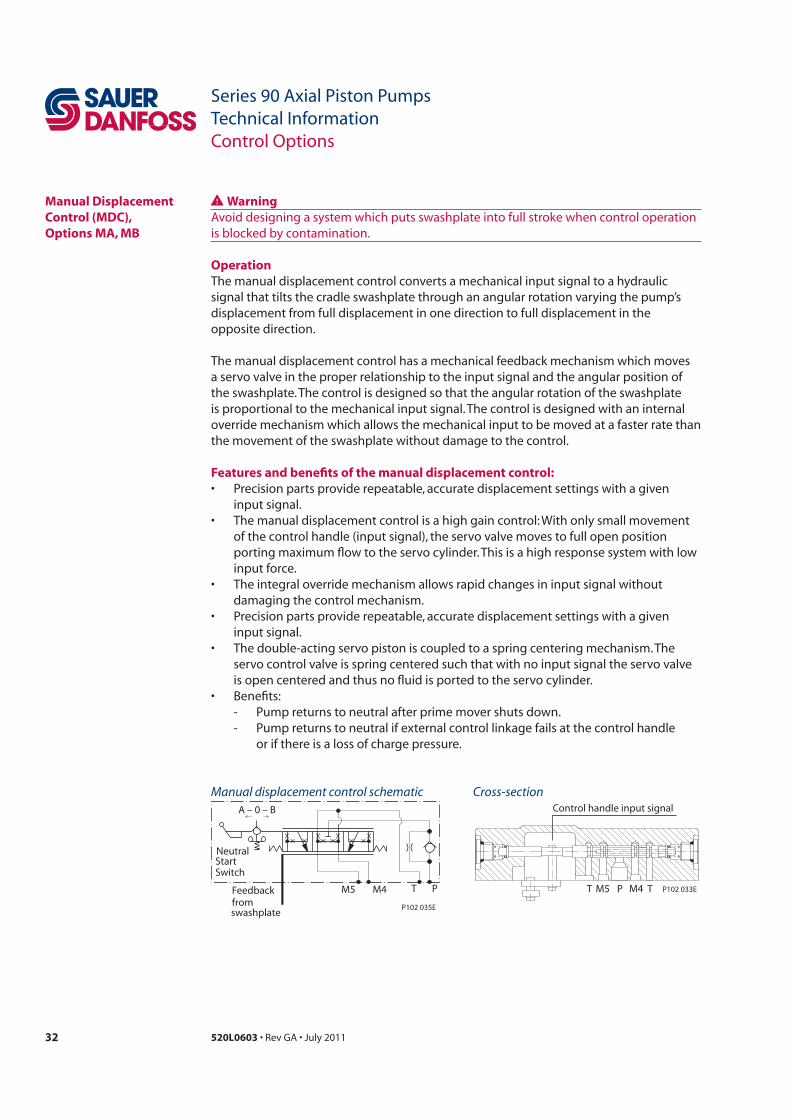
Warning
Operation
displacement from full displacement in one direction to full displacement in the
Features and benefits of the manual displacement control:
- Pump returns to neutral if external control linkage fails at the control handle
Manual displacement control schematic
M4M5 T PFeedbackfromswashplate
A – 0 – B
Switch
NeutralStart
P102 035E
Cross-section
T M5 P M4 T
Control handle input signal
P102 033E
33520L0603
Series 90 Axial Piston PumpsTechnical InformationControl Options
Manual Displacement Control (MDC) Options MA, MB(continued)
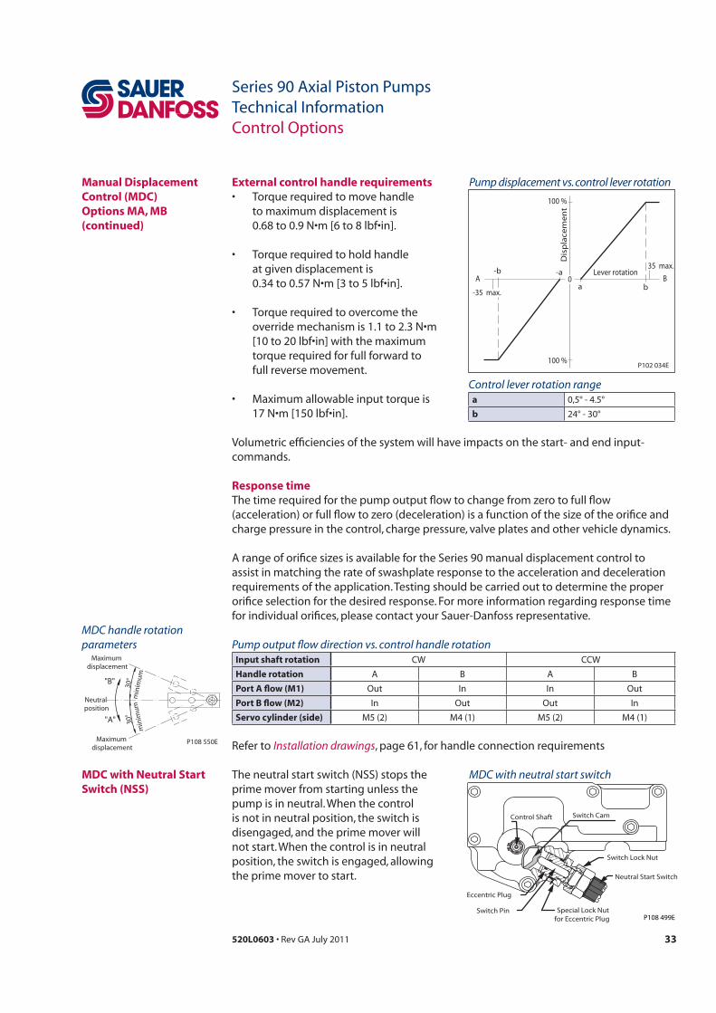
External control handle requirements
to maximum displacement is
Pump output flow direction vs. control handle rotationInput shaft rotation
Handle rotation A B A B
Port A flow (M1) Out In In Out
Port B flow (M2) In Out Out In
Servo cylinder (side)
Installation drawings
Pump displacement vs. control lever rotation
0Lever rotation
A
Dis
pla
cem
en
t
100 %
a
-a
100 %
B-b
b
P102 034E
-35 max.
35 max.
Response time
assist in matching the rate of swashplate response to the acceleration and deceleration
Neutral Start Switch
Eccentric Plug
Switch Pin Special Lock Nutfor Eccentric Plug
Switch Lock Nut
Control Shaft Switch Cam
P108 499E
MDC with neutral start switchMDC with Neutral Start Switch (NSS)
"B"
"A"
30°
min
imum
30°
min
imum
Neutral position
Maximum displacement
Maximum displacement
P108 550E
MDC handle rotation parameters
Control lever rotation rangea
b

34 520L0603
Series 90 Axial Piston PumpsTechnical InformationControl Options
B
A
M5 M4
M3
M1
M2
L1 S L2
M6
P003 174
NFPE Schematic
Non Feedback Proportional Electric Control (NFPE)
"0"
Signal Current mA(DC)
a b c
abc
Dis
plac
emen
t
100 %
100 %
NFPE control
∆p =
300
bar
∆p =
300
bar
∆p =
0 b
ar
∆p =
0 b
ar
P003 187E
Pump Displacement vs. Input Signal
best means of controling the swashplate
Control response
optional control passage orifices to assist in matching the rate of swashplate response
or rate limiting should be used to control
35520L0603
Series 90 Axial Piston PumpsTechnical InformationControl Options
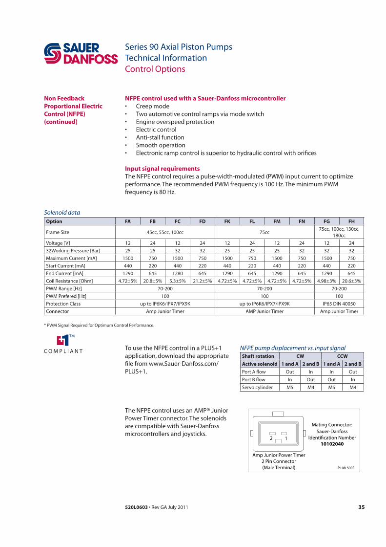
NFPE control used with a Sauer-Danfoss microcontroller
Input signal requirements
NFPE pump displacement vs. input signalShaft rotation CW CCW
Active solenoid 1 and A 2 and B 1 and A 2 and B
Port A flow Out In In Out
Port B flow In Out Out In
M4 M4
Non Feedback Proportional Electric Control (NFPE)(continued)
Solenoid dataOption FA FB FC FD FK FL FM FN FG FH
Frame Size 45cc, 55cc, 100cc 75cc75cc, 100cc, 130cc,
180ccVoltage [V] 12 24 12 24 12 24 12 24 12 2432Working Pressure [Bar] 25 25 32 32 25 25 25 32 32 32Maximum Current [mA] 1500 750 1500 750 1500 750 1500 750 1500 750Start Current [mA] 440 220 440 220 440 220 440 220 440 220End Current [mA] 1290 645 1280 645 1290 645 1290 645 1290 645Coil Resistance [Ohm] 4.72±5% 20.8±5% 5.3±5% 21.2±5% 4.72±5% 4.72±5% 4.72±5% 4.72±5% 4.98±3% 20.6±3%PWM Range [Hz] 70-200 70-200 70-200PWM Prefered [Hz] 100 100 100Protection Class up to IP6K6/IPX7/IPX9K up to IP6K6/IPX7/IPX9K IP65 DIN 40050Connector Amp Junior Timer AMP Junior Timer Amp Junior Timer
P108 500E
2 1
Amp Junior Power Timer2 Pin Connector(Male Terminal)
Mating Connector:Sauer-Danfoss
Identification Number10102040
are compatible with Sauer-Danfoss
36 520L0603
Series 90 Axial Piston PumpsTechnical InformationFeatures and Options
Multi-Function Valves Overpressure protection
Pressure limiting function

37520L0603
Series 90 Axial Piston PumpsTechnical InformationFeatures and Options
Bypass Function
C Caution
C Caution
Multi-Function Valves(continued)
Multifunction valve, pressure limiter, pressure regulation, option 1
M
B
L2
M2
M1
M4
M5
M3A
S
Chargepressurerelief valve
Multifunction valve
Multifunction valve
To control
Servo piston
Servo piston
Port A
Port BC
Bypass hexadjustment
P102 007E
Servo pressurerelief valves
A
B

38 520L0603
Series 90 Axial Piston PumpsTechnical InformationFeatures and Options
Auxiliary Mounting Pads
Auxiliary mounting pad specificationsMounting pad Option code Spline coupling
042 055 075 100 130 180 250
SAE A AB
SAE B BC
SAE B-B BB
SAE C CD
SAE D DE
SAE E EF
SAE E
Mating pump requirements
Pump mounting flanges and shafts with the dimensions noted below are compatible
Auxiliary pump dimensionsFlange size Units P diameter B maximum D F minimum
SAE A
mm
[in]
SAE B
SAE B-B
SAE C
SAE D
SAE E
SAE E
Auxiliary pump mounting flange and shaft
Ø P
0 -0.0
5[+
0.00
0][-
0.00
2]
Fmin.
Minimum spline engagement
D
Bmax.
E
Mounting flange (Ref)
Coupling
0.8 [0.03] R
preferred P102 015E

39520L0603
Series 90 Axial Piston PumpsTechnical InformationFeatures and Options
Displacement Limiter
Displacement limiterDisplacement limiter location
Pump rotation
Displacement
limiter mounted
on servo side
Displacement
limitation at high
pressure side
A
B
B
A
Warning
Frame size Lock nut wrench size and torque Adjusting screw
wrench size
internal hex
Approximate displacement change
per revolution of adjusting screw
4 mm
4 mm
4 mm
4 mm

40 520L0603
Series 90 Axial Piston PumpsTechnical InformationFeatures and Options
Shaft Torque Shaft torque and spline lubricationThe rated torque
9
c
Maximum torque
Shaft torque for tapered shaftsThe rated torque is based on the contact pressure between the shaft and hub surfaces
Maximum torque
Plug-in rigidShaft Availability and Torque Ratings
41520L0603
Series 90 Axial Piston PumpsTechnical InformationFeatures and Options
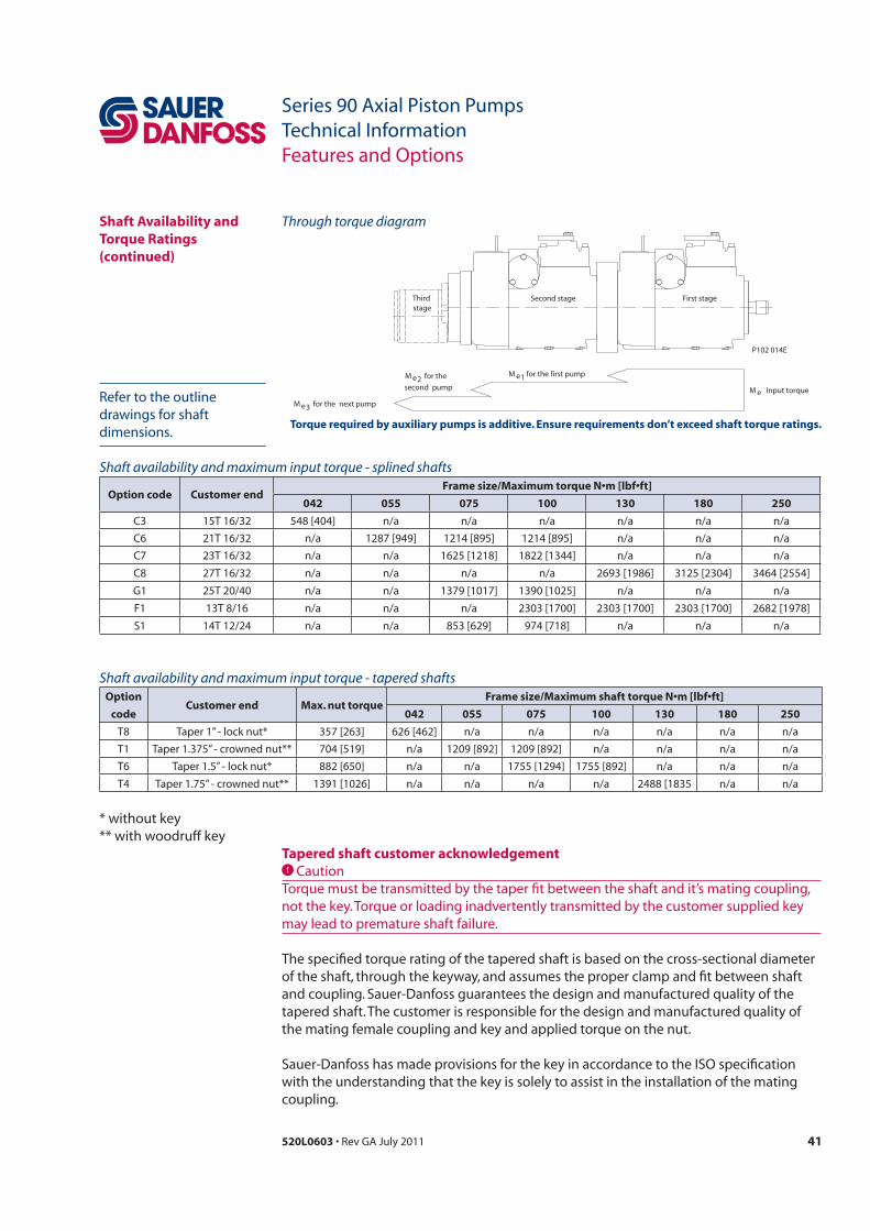
Shaft Availability and Torque Ratings(continued)
First stageSecond stageThird stage
for the first pumpM e1second pump
for the M e2
next pumpfor the M e3
Input torqueM e
P102 014E
Through torque diagram
Torque required by auxiliary pumps is additive. Ensure requirements don’t exceed shaft torque ratings.drawings for shaft
Tapered shaft customer acknowledgementCCaution
Shaft availability and maximum input torque - splined shafts
Option code Customer end042 055 075 100 130 180 250
Shaft availability and maximum input torque - tapered shaftsOption
codeCustomer end Max. nut torque
042 055 075 100 130 180 250
T4

42 520L0603
Series 90 Axial Piston PumpsTechnical InformationFeatures and Options
Charge Pump
Charge pump sizing/selectionIn most applications a general guideline is that the charge pump displacement should
Selection of Drive line Components BLN-9885
Available charge pump sizes and speed limitsCode Charge pump size Rated speed
min-1 (rpm)
B
C
D
E
F
43520L0603
Series 90 Axial Piston PumpsTechnical InformationFeatures and Options
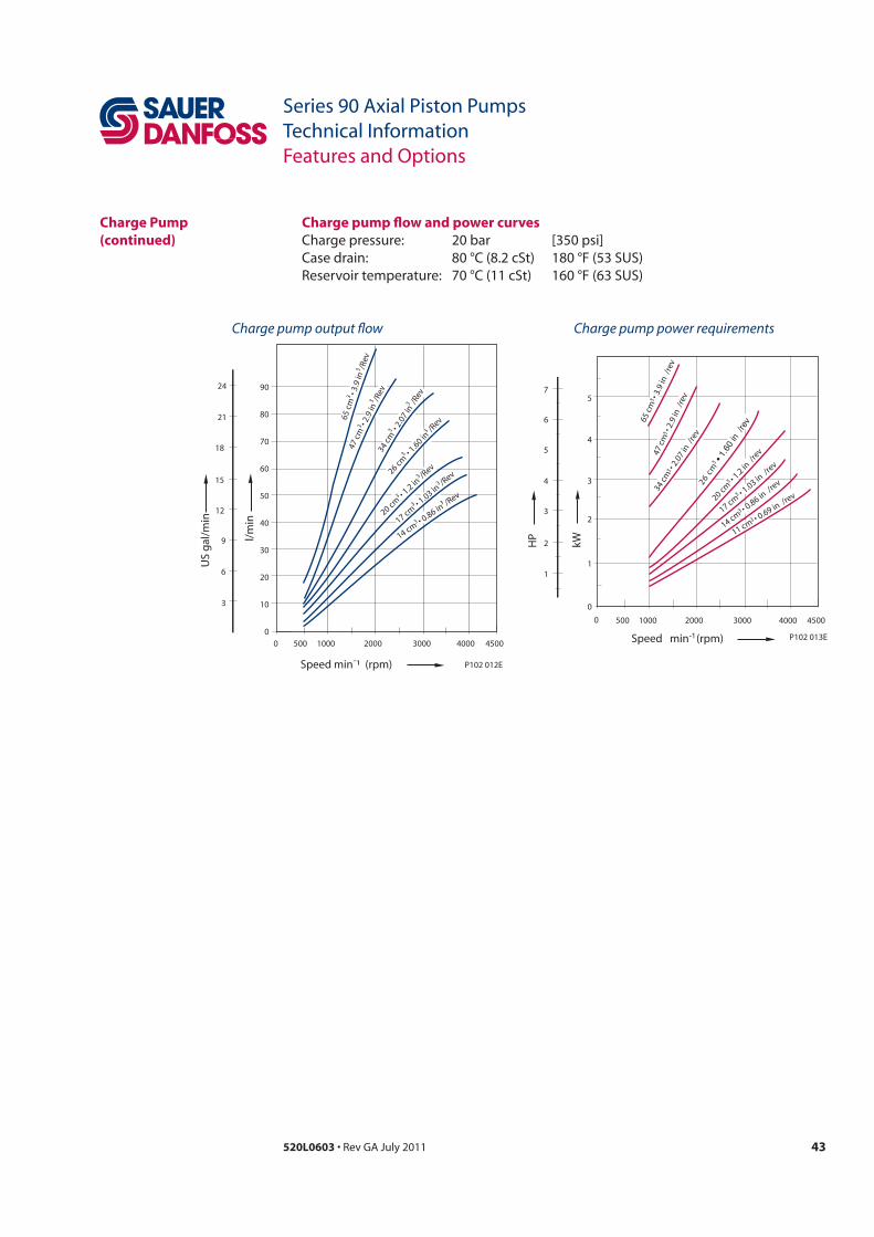
Charge Pump(continued)
Charge pump power requirementsCharge pump output flow
80
70
60
50
40
30
20
103
6
9
12
15
21
18
500 1000 2000 3000 4000 4500
Speed min¯¹ (rpm)
US
gal
/min
l/m
in
3
3
3
3
3
3
33
3
3
00
3
3
9024
3
3
P102 012E
3
2
1
6
500 1000 2000 3000 4000 4500
HP
kW
34 c
m
26 cm
1 cm
1
3
14 cm
5
4
3
2
1
4
0
0
3
3
3
3
3
3
3
65 c
m 35
P102 013E
Charge pump flow and power curves

44 520L0603
Series 90 Axial Piston PumpsTechnical InformationFeatures and Options
Speed Sensor
Pulse frequency042 055 075 100 130 180 250
10106825
Warning
KPP Pulse Pickup (PPU)Technical Information 11029257
Electrical and Environmental DataElectricalSupply voltage (two ranges)Regulated 4.5 to 8.5 Vdc
Battery 7 to 32 VdcMaximum operating current20 mA at 1 Hz and 5 Vdc supplyRequired current12 mA at 5 Vdc (no load) Output voltage in high stateSupply voltage minus 0.5 Vdc minimum (no load)Output voltage in low state0.5 Vdc, maximum (no load)Maximum frequency15 kHzLoad15 kΩ to both ground and supplyPeak transient voltage80 Vdc for 2 milliseconds, 4.5 to 8.5 Vdc models
300 Vdc for 2 milliseconds, 7 to 32 Vdc models
200 Vdc for 100 milliseconds, 7 to 32 Vdc models
Peak reverse voltage-15 Vdc continuous, 4.5 to 8.5 Vdc models -32 Vdc continuous, 7 to 32 Vdc modelsEnvironmentalOperating and storage temperature-40° to 110° C [-40° to 230° F]
45520L0603
Series 90 Axial Piston PumpsTechnical InformationFeatures and Options
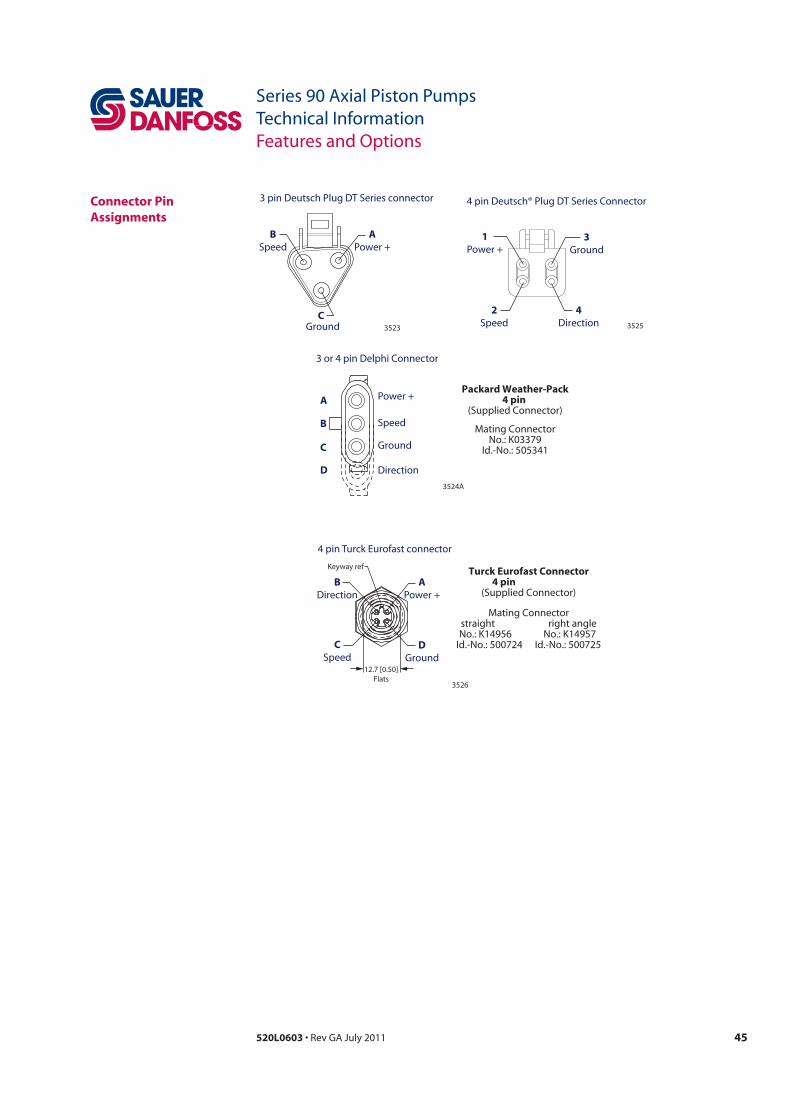
CGround
3 pin Deutsch Plug DT Series connector
3523
APower +
BSpeed
3 or 4 pin Delphi Connector
Power +
Speed
Ground
Direction
A
B
C
D3524A
4 pin Deutsch® Plug DT Series Connector
1Power +
3Ground
2Speed
4Direction 3525
3526
4 pin Turck Eurofast connector
Keyway ref
APower +
DGround
12.7 [0.50]Flats
CSpeed
BDirection
Packard Weather-Pack4 pin
(Supplied Connector)
Mating ConnectorNo.: K03379
Id.-No.: 505341
Turck Eurofast Connector4 pin
(Supplied Connector)
Mating Connectorstraight right angleNo.: K14956 No.: K14957
Id.-No.: 500724 Id.-No.: 500725
Connector Pin Assignments

79520L0603
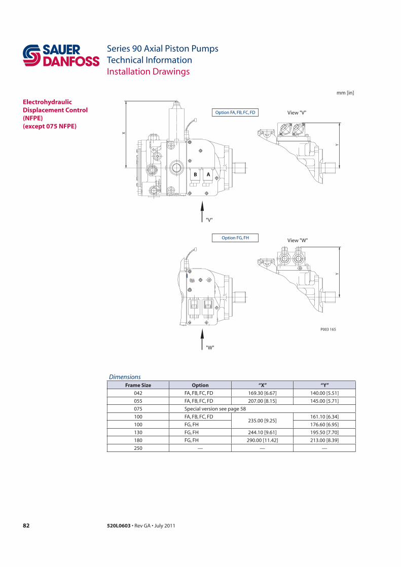
Series 90 Axial Piston PumpsTechnical InformationInstallation Drawings
mm [in]
Option CA
View "W"
C3
"W"
C1
C1
C2
PortM4
C4
max
imu
mC
4 m
axim
um
PortM5
Displacement limiteroption 4
limitation both sides
P102065
View "W"
C5
max
imu
m
Option DC & DD
"W" P102065a
a
b
C5.
1C
5.2
Cover Plate
DimensionsFrame size C1 C2 C3 C4 maximum (option 4)
- - -
- - -
3-Position (F-N-R) Electric Control
DimensionsFrame size C5 maximum C5.1 C5.2

80 520L0603
Series 90 Axial Piston PumpsTechnical InformationInstallation Drawings
mm [in]
C7
(Fra
me
size
042
on
ly)
Frame size 042 only
C7
View "W"
P102 066
"W"
C6
PortX1
Port X2
Option KA & KPPackard-
Connectoroption KP
Electric Displacement Control (EDC) with MS-Connector or Packard® connector
DimensionsFrame size C6 C7
Option HF View "W"
C8.
2 (p
ort
X1)
C9
C11
Port X1 C12
C10
Port X2
"W"
C8.
1 (p
ort
X2)
DimensionsFrame size C8.1 C8.2 C9 C10 C11 C12
Hydraulic Displacement Control (HDC)

81520L0603
Series 90 Axial Piston PumpsTechnical InformationInstallation Drawings
mm [in]
Manual Displacement Control (MDC) with neutral start switch
DimensionsFrame size C13 C14
Option MB View "W"
C14
"W"
Neutral start switch
C13
P102 067
82 520L0603
Series 90 Axial Piston PumpsTechnical InformationInstallation Drawings
mm [in]
"V"
"W"
View "V"
View "W"
Y
X
Y
P003 165
Option FA, FB, FC, FD
Option FG, FH
B A
DimensionsFrame Size Option “X” “Y”
— — —
Electrohydraulic Displacement Control (NFPE) (except 075 NFPE)

83520L0603
Series 90 Axial Piston PumpsTechnical InformationInstallation Drawings
mm [in]
F4 maximum
Gauge port M3charge pressureafter filter9/16-18UNF
View "X"
Gauge port M6charge pressurebefore filter9/16-18UNF
Option P & L
"X"
F1 = short filter cartridge (option P)
F2 = long filter cartridge (option L)
F3
22.86[0.90]
20.3 minimum [0.80 minimum]
Required for removal
180
180
Option R & TView "X"
Port Efrom filter7/8-14UNF (option R)
1 1/16 -12UN (option T)
5.6
[0.2
2]
5.6
[0.2
2]
Port Dto filter7/8-14UNF(option R)
1 1/16 -12UN(option T)
F5 maximum
F6 maximum
F7 maximum
"X"
F3
Gauge port M3charge pressureafter filter9/16-18UNF
180
180
28.5[1.12]
Ø 9
4.2
max
imu
m[Ø
3.7
1 m
axim
um
]
Frame size 042 – 130 = option RFrame size 180 – 250 = option T
Frame size 042 – 130 = option PFrame size 042 – 250 = option L
P102 068
Integral Pressure Filter
Remote pressure – without filter
DimensionsFrame size F1 F2 F3 F4 maximum F5 maximum F6 maximum F7 maximum
- - -
- - -
Local address:
Sauer-Danfoss GmbH & Co. OHGPostfach 2460, D-24531 NeumünsterKrokamp 35, D-24539 Neumünster, GermanyPhone: +49 4321 871 0Fax: +49 4321 871 122
Sauer-Danfoss ApSDK-6430 Nordborg, DenmarkPhone: +45 7488 4444Fax: +45 7488 4400
Sauer-Danfoss is a global manufacturer and supplier of high-quality hydraulic and electronic components. We specialize in providing state-of-the-art technology and solutions that excel in the harsh operating conditions of the mobile off -highway market. Building on our extensive applications expertise, we work closely with our customers to ensure exceptional performance for a broad range of off -highway vehicles.
We help OEMs around the world speed up system development, reduce costs and bring vehicles to market faster. Sauer-Danfoss – Your Strongest Partner in Mobile Hydraulics.
Go to www.sauer-danfoss.com for further product information.
Wherever off -highway vehicles are at work, so is Sauer-Danfoss.
We off er expert worldwide support for our customers, ensuring the best possible solutions for outstanding performance. And with an extensive network of Global Service Partners, we also provide comprehensive global service for all of our components.
Please contact the Sauer-Danfoss representative nearest you.
Products we off er:
Bent Axis Motors
Closed Circuit Axial Piston Pumps and Motors
Displays
Electrohydraulic Power Steering
Electrohydraulics
Hydraulic Power Steering
Integrated Systems
Joysticks and Control Handles
Microcontrollers and Software
Open Circuit Axial Piston Pumps
Orbital Motors
PLUS+1™ GUIDE
Proportional Valves
Sensors
Steering
Transit Mixer Drives
Members of the Sauer-Danfoss Group:
Comatrolwww.comatrol.com
Schwarzmüller-Inverterwww.schwarzmueller-inverter.com
Turolla www.turollaocg.com
Hydro-Gear www.hydro-gear.com
Sauer-Danfoss-Daikinwww.sauer-danfoss-daikin.com
Sauer-Danfoss (US) Company2800 East 13th StreetAmes, IA 50010, USAPhone: +1 515 239 6000Fax: +1 515 239 6618
Sauer-Danfoss-Daikin LTD.Shin-Osaka TERASAKI 3rd Bldg. 6F1-5-28 Nishimiyahara, Yodogawa-kuOsaka 532-0004, JapanPhone: +81 6 6395 6066Fax: +81 6 6395 8585
w w w . s a u e r - d a n f o s s . c o m520L0603


