A - 179PNEUMATICS
AirCylinder
�
Series ADQWith Auto Switch/Double Acting Type, Single Acting TypeBore Size (mm) : ф12, ф16, ф20, ф25, ф32, ф40, ф50, ф63, ф80, ф100
How to Order
Model/Standard Stroke
Bore Size
(mm)
ф12
ф16
ф20
ф25
ф32
ф40
ф50
ф63
ф80
ф100
Double acting
For details, please refer to Page.A-161
Standard Stroke(mm)
5, 10, 15, 20, 25,30, 35, 40, 45, 50,75
5, 10, 15, 20, 25,30, 35, 40, 45, 50,75, 100, 125, 150
5, 10, 15, 20, 25,30, 35, 40, 45, 50,75, 100, 125, 150
5, 10, 15, 20, 25,30, 35, 40, 45, 50,75, 100, 125, 150
5, 10, 15, 20, 25,30, 35, 40, 45, 50,75, 100
5, 10, 15, 20, 25,30, 35, 40, 45, 50,75
10, 15, 20, 25, 30, 35, 40, 45, 50, 75,100, 125, 150
10, 15, 20, 25, 25, 30, 35, 40, 45, 50,75, 100
10, 15, 20, 25, 25, 30, 35, 40, 45, 50,75, 100 10, 15, 20, 25, 25,
30, 35, 40, 45, 50,75, 100, 125, 150
_
5, 10, 15, 20, 25,30, 35, 40, 45, 50
5, 10, 15, 20, 25,30, 35, 40, 45, 50, 75
5, 10_
10
_
10
_
5, 10_
5, 10 5, 10
Single Double Non-Rotating Rear Boss Spring Spring
Rod Type Rod Type Rod Type Mount Type Return Type Extended Type
5, 10, 15 _ _ 5, 10, 15 _ _
20, 25, 30 20, 25, 30
Single acting
Applicable
Auto
Switch
Grommet
Type
W4
Standard Stroke(mm) Reed Switch
Intermediate Stroke
A Spacer of 5, 10, 15 and 20mm is used for intermediate stroke between 55 and 100mm stroke(55, 60, 65...).
(Example) AQB50-55D is produced by installing 20mm spacer in AQB50-75.
� SPACE SAVING DESIGN
� LIGHT WEIGHT
� 10 BORE SIZES
� AUTO SWITCH CAPABLE
� CYLINDERS FOR SPECIAL APPLICATIONS
� MANUFACTURING CERTIFIED TO
ISO 9001&9002 STANDARDS
Symbol
Double Acting /
Single Rod Type
Double Acting /
Double Rod Type
A-160~203 2002.7.18 7:0 PM 페이지179
A - 180PNEUMATICS
AirCylinder
�
Series ADQ
Body Optional
Auto Switch Specification
Standard/Specifications
Auto Switch Model
Application
Load Voltage
Range of Load Current
Protection Circuit for Contact Braker Point
Internal Voltage Drop
Indicator Lamp
● Leak Current - Non
● Response Time - 1.2ms
● Lead Wire - Oil Proof vinyl, ф3.4, 0.2㎟ 2wire(red, black), ※
● Impact Resistance - 30G
● Insulation Resistance - 50MΪ or more under the test voltage 500VDC(between case and cable)
● Dielectric Resistance - 1500VAC 1min(between case and cable)
● Ambient Temperature
● Protection Structure - IEC spec IP67, Water-proof, Oil-proof.
※ If 300mm lead wire is required, L is put at the end of model numbers.
(Example) W4L
W4
Relay, Sequence Control
120VAC, 24VDC
5~40 mA 5~20 mA
Non
2.4V or Less
ON : Red Light Emitting Diode
Min. Auto Switch Mountable Stroke
No. of Auto SwitchMin. Auto SwitchMountable Stroke
With 1pc
With 2pcs
5mm
10mm
Reed Switch Type (Please Refer to Page A-202)
Fluid Air
Max. Operating Pressure 1.0MPa (9.9kgf/cm2)
Min. Operating Pressure 0.5kgf/cm2 {ф12ф16: 0.7kgf/cm2}
Ambient and Fluid Temperature -10~60℃
Lubrication Not Required
Cushion None
Rod End Thead Female (Standard Type)
Stroke Tolerance mm
Mounting Through Hole (Standard)
Piston Speed 50~500mm/sec
Non - Rotating Rod Accuracy (Non-Rotating Piston Rod Type
Bore Size mm
Non-Rotating Rod Accuracy
ф20 ф32 ф40 ф50 ф63
�1� �0.8�
+1.00
Name Applicable Type
Cushion Rubber Cushion
Rod End Male Thread Option
Boss Mount Rear Boss Mount Type (Optional)
Non-Rotating Rod Type Double Acting/Single Rod Type Only
A-160~203 2002.7.18 7:0 PM 페이지180
A - 181PNEUMATICS
AirCylinder
�
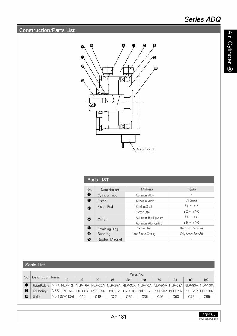
Construction/Parts List
Series ADQ
Parts LIST
No. Descritpion Material Note
�
�
�
�
�
�
�
Cylinder Tube
Piston
Piston Rod
Collar
Retaining Ring
Bushing
Rubber Magnet
Aluminum Alloy
Aluminum Alloy
Stainless Steel
Carbon Steel
Aluminum Bearing Alloy
Aluminum Alloy Casting
Carbon Steel
Lead Bronze Casting
-
-
Chromate
ф12 ~ ф25
ф32 ~ ф100
ф12 ~ ф40
ф50 ~ ф100
Black Zinc Chromate
Only Above Bore:50
-
Seals List
No.
�
�
�
Description
Piston Packing
Rod Packing
Gasket
MaterialParts No.
NLP-12
DYR-6K
SO-013-6
NLP-16A
DYR-8K
C14
NLP-20A
DYR-10SK
C18
NLP-25A
DYR-12
C22
NLP-32A
DYR-16
C29
NLP-40A
PDU-16Z
C36
NLP-50A
PDU-20Z
C46
NLP-63A
PDU-20Z
C60
NLP-80A
PDU-25Z
C75
NLP-100A
PDU-30Z
C95
NBR
NBR
NBR
Auto Switch
�
� ��
�
� �
�
�
�
�
12 16 20 25 32 40 50 63 80 100
A-160~203 2002.7.18 7:0 PM 페이지181
A - 182PNEUMATICS
AirCylinder
�
Series ADQ
Stroke (mm)
Auto Switch Mounting Date
Weight/Double Acting, Single Rod
Bore Size
AdditionalWeight for
Male Thread5 10 15 20 25 30 35 40 45 50 75 100
40
61
91
118
157
272
-
-
-
-
47
72
112
139
180
294
401
647
1443
2208
54
83
132
160
202
316
439
687
1534
2314
61
94
152
181
225
338
476
727
1624
2420
68
105
173
203
248
360
514
767
1714
2526
75
116
193
224
270
382
551
807
1804
2632
-
-
213
245
292
404
589
847
1894
2738
-
-
234
266
316
426
626
987
1985
2844
-
-
254
287
339
448
663
927
2076
2950
-
-
274
309
362
470
701
967
2166
3056
-
-
-
-
522
623
958
1257
2830
3801
-
-
-
-
636
733
1102
1464
3296
4318
2
3
7
17
40
40
80
80
160
270
(㎏f)
�U
�U A
Auto Switch Mounting Position
Bore size
(mm)
A(mm)
B(mm)
U(mm)
5
8
8
8
9.5
13.5
11.5
14
18
21.5
6
5.5
7
7.5
6.5
9
12
15
18.5
24.5
19.5
22.5
24.5
27.5
31.5
35
41
47.5
57.5
67.5
BA B
Bore size: ф12~ф25
W4
Bore Size: ф32~ф100
ф12
ф16
ф20
ф25
ф32
ф40
ф50
ф63
ф80
ф100
ф12
ф16
ф20
ф25
ф32
ф40
ф50
ф63
ф80
ф100
A-160~203 2002.7.18 7:0 PM 페이지182
A - 183PNEUMATICS
AirCylinder
�
Rear Boss Mount
Rod End Male Thread
G
H
Rod End nutC
X
L1
фTh9
H Screw depth C
20
Auto Switch
(2-M5×0.8)
B+Stroke Port size
Q F
L
фD
A+Stroke
10
S
�U
2-фNThrough holeK
M±0.2
E
�V
4-фO Counter
Bore
Minimum bend radiusof lead wire 10
Bore Size: ф12~ф25
Rod End Male Thread
Bore size
(mm)
ф12
ф16
ф20
ф25
9
10
12
15
C X L1
10.5
12
14
17.5
14
15.5
18.5
22.5
H
Series ADQ
With Auto Switch : Double Acting/Single Rod Type : Dimensions
M5×0.8
M6×1.0
M8×1.25
M10×1.25
Standard Type
Rear Boss Mount
Bore size (mm)
ф12
ф16
ф20
ф25
G
1.5
1.5
2
2
Th9
15
20
13
15
Bore size(mm)
ф12
ф16
ф20
ф25
5~30
5~30
5~50
Stroke range(mm)
H фO Q S U V
6.5 Depth3.5
6.5 Depth 3.5
9 Depth 7
9 Depth 7
11
10
10.5
11
35.5
41.5
48
53.5
19.5
22.5
24.5
27.5
25
29
36
40
5
6
8
10
3.5
3.5
5
22
28
36
40
3.5
3.5
6.5
5.5
K L M N
31.5
34
37.5
28
30.5
32.5
6
8
7
12
6
8
10
12
32
38
47
52
6.5
5.5
5.5
5.5
A B C D E F
5~5075
3655.5
4.514.5
31.541
0-0.043
0-0.052
0-0.0430-0.043
(unit:mm)
M3×0.5
M4×0.7
M5×0.8
M6×1.0
For the Dimension of “A”type (Both End Tapped)Please refer to Page A-196
A-160~203 2002.7.18 7:0 PM 페이지183
A - 184PNEUMATICS
AirCylinder
�
Series ADQ
With Auto Switch : Double Acting/Single Rod Type : Dimensions
Rear Boss Mount (Unit : mm)
Bore size
(mm)
ф32
ф40
ф50
ф63
ф80
ф100
ф32
ф40
ф50
ф63
ф80
ф100
Th9
21
28
35
35
43
59
Bore Size : ф32~ф100
0-0.0520
-0.052
0-0.062
0-0.062
0-0.062
0-0.074
G
Standard
Bore size(mm)
M8×1.25
M8×1.25
M10×1.5
M10×1.5
M16×2.0
M20×2.5
9 Depth 7
9 Depth 7
11 Depth 8
14 Depth 10.5
17.5 Depth 13.5
17.5 Depth13.5
Rc(PT) 1/8
Rc(PT) 1/8
Rc(PT) 1/4
Rc(PT) 1/4
Rc(PT) 3/8
Rc(PT) 3/8
Stroke range( mm)5~50
75, 100125, 1505~5075,100
125, 15010~5075,100
125, 15010~5075,100
125, 15010~5075,100
125, 15010~5075,100
125, 150
A B C D E F H фO PI J K L M N Q S U Z
58.531.5 18
66 35 18
80 41 22
93 47.5 22
112.557.5 26
132.567.5 26
40 33
62.5 45.5
46.5 39.5
72 55
48.5 40.5
73.5 55.5
54 46
75 57
63.553.5
86 66
75 63
97.5 75.5
13 16 45
13 16 52
15 20 64
15 20 77
21 25 98
27 30 117
60 4.5 14 34 5.5
69 5 14 40 5.5
86 7 17 50 6.6
103 7 17 60 9
132 6 22 77 11
156 6.5 27 94 11
7.5
12.5
8
14
10.5
14
10.5
16.5
12.5
19
13
23
717
717
818
818
1020
1222
10.512.5
1114
10.5
14
1516.5
1619
23
(Unit : mm)
2-PQ F
H
2
фTh9
фD
Z
M±
0.2
E20
10
Rod End NutC
X
L1
H Screw depth C
4-фN Through Hole≒U
Auto Switch
K
Q
0.2
2-P
Port size
J
M±0.2
E
S
Minimum Bend Radiusof Lead Wire 10
8-фO Counter Bore
Long Stroke(125st or more)
фI
фThg
(mm)
Bore size
32
40
50�63
80
100
T
22
28
35
43
59
0-0.0520-0.0520-0.0620-0.0620-0.074
Rod End Male Thread (Unit : mm)
Bore size
(mm)
20.5
20.5
26
26
32.5
32.5
C X L1
23.5
23.5
28.5
28.5
35.5
35.5
28.5
28.5
33.5
33.5
43.5
43.5
M14×1.5
M14×1.5
M18×1.5
M22×1.5
M22×1.5
M26×1.5
H
Port size
B+stroke
A+stroke
Rear Boss Mount
Rod End Male Thread
ф32
ф40
ф50
ф63
ф80
ф100
For the Dimension of “A”type (Both End Tapped)Please refer to Page A-196
A-160~203 2002.7.18 7:0 PM 페이지184
A - 185PNEUMATICS
AirCylinder
�
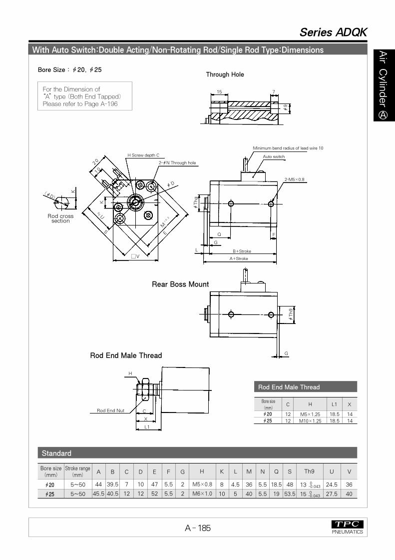
With Auto Switch:Double Acting/Non-Rotating Rod/Single Rod Type:Dimensions
Series ADQK
Standard
Bore size(mm)
5~50
5~50
Stroke range (mm)
H Th9 U V
24.5
27.5
36
40
M5×0.8
M6×1.0
13
15
A B C D E F G K L M N Q S
8
10
4.5
5
36
40
5.5
5.5
18.5
19
48
53.5
44
45.5
39.5
40.5
7
12
10
12
47
52
5.5
5.5
2
2
0-0.043
0-0.043
15 7
Minimum bend radius of lead wire 10
Auto switch
ф9
A+Stroke
Rear Boss Mount
Rod End Male Thread
B+Stroke
FQ
G
L
2-M5×0.8
C
X
L1
G
Rod End Nut
H
H Screw depth C
2-фN Through hole
�V
фD
Rod cross section
(фD)
K
≒U
S
20
10
K
EM
±0.2
фThg
фTh9
Bore Size : ф20, ф25Through Hole
Rod End Male Thread
Bore size
(mm)
ф20
ф25
ф20
ф25
12
12
C XL1
14
14
18.5
18.5
M5×1.25
M10×1.25
H
For the Dimension of “A”type (Both End Tapped)Please refer to Page A-196
A-160~203 2002.7.18 7:0 PM 페이지185
A - 186PNEUMATICS
AirCylinder
�
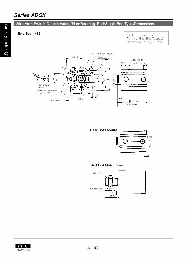
Series ADQK
With Auto Switch:Double Acting/Non-Rotating Rod/Single Rod Type:Dimensions
Rear Boss Mount
Rod End Male Thread
4-ф5.5Through hole≒31.5
Minimum bend radiusof lead wire 10
Auto switch
M8×1.25 Screw Depth 13
2-Rc(PT) 1/8
Port Size19.5
(ф16)
20
10
2
7
49+Stroke
42+Stroke
ф21-
0 -0.0
52
ф21-
0 -0.0
52
ф16ф60
45
18
14
34
±0.2
45 4.5
58.5
34±0.2
M14×1.5
20.5
23.5
28.5
Rod End Nut
2
(14)
Rod cross section
7.5
Bore Size : ф32For the Dimension of
“A”type (Both End Tapped)Please refer to Page A-196
A-160~203 2002.7.18 7:0 PM 페이지186
A - 187PNEUMATICS
AirCylinder
�
Series ADQK
Bore Size : ф40~ф63
Rear Boss Mount
Rod End Male Thread
4-ф N Through hole
8-фO Counter bore
≒U
Minimum bend radius of lead wire 10
Auto switch
H Screw Depth C
2-P
Q
(фD)
20
10
2
L
A+Stroke
B+Strokeф
Thg
фTh9
фDфI
EZK
M±
0.2
E J
S
M±0.2
H
CX
L1
Rod End Nut
2
(K)
Rod crosssection
F
With Auto Switch:Double Acting/Non-Rotating Rod/Single Rod Type:Dimensions
Standard
Rear Boss Mount (mm)
0-0.062
Rod End Male Thread (mm)
Bore sizemm
ф40
ф50
ф63
Th9
28
35
35
Bore size(mm)
ф40
ф50
ф63
C L1 X
20.5
26
26
28.5
33.5
33.5
23.5
28.5
28.5
M14×1.5M18×1.5M18×1.5
H
0-0.0520-0.062
Bore size(mm)
ф40
ф50
ф63
Stroke range(mm)5~50
75, 10010~5075, 10010~5075, 100
46.5
48.5
54
39.5
40.5
46
H
M8×1.25
M10×1.5
M10×1.5
фO
9 Depth7
11Depth8
14Depth10.5
Thg
28
35
35
P
Rc(PT) 1/8
Rc(PT) 1/4
Rc(PT) 1/4
A B C D E F
13
15
15
16
20
20
52
64
77
8
10.5
10.5
I J K L M N
69
86
103
5
7
7
14
18
18
7
8
8
40
50
60
5.5
6.6
9
Q S
11
10.5
15
66
80
93
Z
18
22
22
U
35
41
47.5
0-0.052
0-0.062
0-0.062
For the Dimension of “A”type (Both End Tapped)Please refer to Page A-196
A-160~203 2002.7.18 7:0 PM 페이지187
A - 188PNEUMATICS
AirCylinder
�
With Auto Switch: Double Acting/Double Rod Type: Dimensions (inch)
Series ADQW
Bore size(mm)
ф20
ф25
5~75
5~50
Stroke range(mm)
H фO
9 Depth7
9 Depth7
Q S U V
10.5
11
48
53.5
24.5
27.5
36
40
M5×0.8
M6×1.0
A B C D E K L M N
8
10
4.5
5
36
40
5.5
5.5
47
49
38
39
7
12
10
12
47
52
Standard (Unit : mm)
20
H Screw Depth C10
(Available on theopposite side)
≒U
S
�V
M±0.2
K
E
фD
2-фNThrough hole
4-фO Counterbore
L
Q Q
B+Stroke
A+2(Stroke)
L+Stroke
Width across flats K2-M5×0.8
фD
Minimum bend radius of lead wire 10
※ Rod End NUt
2-H
C
X
L1+Stroke
Rod End Male Thread
Rod End NutC
X
L1
A+2(Stroke)
Auto switch
Bore Size : ф20 (3/4 Nom.), ф25 (1 Nom.)
Rod End Male Thread (mm)
Bore size
(mm)A C H L1 X
ф20
ф25
M8×1.25
M10×1.25
75
84
12
15
18.5
22.5
14
17.5
For the Dimension of “A”type (Both End Tapped)Please refer to Page A-196
A-160~203 2002.7.18 7:0 PM 페이지188
A - 189PNEUMATICS
AirCylinder
�
With Auto Switch: Double Acting/Double Rod Type: Dimensions (mm)
Series ADQW
Rod End Male Thread (mm)
Bore size
(mm)
ф32ф40ф50ф63ф80ф100
97.5
107
117.5
119
148
157.5
A C L1 X
20.5
20.5
26
26
32.5
32.5
28.5
28.5
33.5
33.5
43.5
43.5
23.5
23.5
28.5
28.5
35.5
35.5
M14×1.5
M14×1.5
M18×1.5
M18×1.5
M22×1.5
M26×1.5
H
Standard
Bore Size : ф32~ф100
(mm)
2-HScrew depth C
8-фO Counter bore
20
10
M±0.2
JE
K
S
Auto Switch
Minimum bend radius of lead wire 10
across flats K
фD
фD
фI
(Available on the opposite side)4-фN Through hole
EZ
M±
0.0
08
Q Q
L B+Stroke L+Stroke
A+2(Stroke)
2-P
�U
XX
Rod End Male Thread
2-H
C
Rod End Nut Rod End Nut
C
L1
A+2(Stroke)
L1+Stroke
Bore size(mm)
Stroke range(mm)
5~75
5~75
10~75
10~75
10~75
10~75
H
M8×1.25
M8×1.25
M10×1.5
M10×1.5
M16×2.0
M20×2.5
I J K L M N
60
69
86
103
132
156
4.5
5
7
7
6
6.5
14
14
17
17
22
27
7
7
8
8
10
12
34
40
50
60
77
94
5.5
5.5
6.6
9
11
11
Q S U Z
12.5
14
14
15.5
18
22
58.5
66
80
93
112.5
132.5
31.5
35
41
47.5
57.5
67.5
18
18
22
22
26
26
фO P
Rc(PT) 1/8
Rc(PT) 1/8
Rc(PT) 1/4
Rc(PT) 1/4
Rc(PT) 3/8
Rc(PT) 3/8
9 Depth7
9 Depth 7
11 Depth 8
14 Depth 10.5
17.5 Depth 13.5
17.5 Depth 13.5
A B C D E
54.5
64
66.5
68
81
94.5
40.5
50
50.5
52
61
70.5
13
13
15
15
21
27
16
16
20
20
25
30
45
52
64
77
98
117
ф32
ф40
ф50
ф63
ф80
ф100
For the Dimension of “A”type (Both End Tapped)Please refer to Page A-196
A-160~203 2002.7.18 7:0 PM 페이지189
A - 190PNEUMATICS
AirCylinder
�
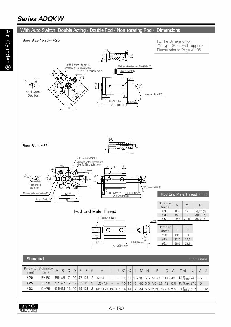
With Auto Switch: Double Acting / Double Rod / Non-rotating Rod / Dimensions
Series ADQKW
15 7
2-фN Through hole
2-H Screw depth C
20
10
(Available on the opposite side)
фD
фTh9
K1
ф9
фD
QL
фD
Minimum bend redius of lead Wire 10
Auto switch
2-P
across flats K2
(K1)
�V
LG
F
Rod CrossSection
E
A+2(Stroke)
B+Stroke L+Stroke
S≒U
M±0.2
Bore Size :ф20~ф25
→
фTh9
Bore Size:ф32
Rod cross Section
2-P
Width across flats K
Q F
※Rod End Nut
A+2(Stroke)
CXL1
C
L1+Stroke
2-H
EM
±0.2
K1 Z
Minimum bend radius of lead wire 10
Auto Switch
20
10
Rod End Male Thread
2-H Screw depth C
4-фN Through hole(Available on the opposite side)
M±0.2
ES
фI
≒U
A+2(Stroke)L1+StrokeB+StrokeL
G
фD
фD
5.5
(K1)
L
Rod End Male Thread (mm)
X
Bore sizeA C H
(mm)
83 12
92 15
106.5 20.5
Bore size
(mm)L1 X
18.5
22.5
28.5
14
17.5
23.5
ф9
7
Standard (Unit : mm)
Bore size(mm)
5~50
5~50
5~75
Stroke range(mm)
H P Th9
M5×0.8
M5×0.8
Rc(PT)1/8
13
15
21
24.5 36 -
27.5 40 -
31.5 - 18
Q S U V Z
18.5 48
19 53.5
21.5 58.5
M5×0.8
M6×1.0
M8×1.25
A B C D E F G I J K1 K2 L M N
- - 8 8 4.5 36 5.5
- - 10 10 5 40 5.5
60 4.5 14 14 7 34 5.5
55 46 7 10 47 10.5 2
57 47 12 12 52 11 2
63.5 49.5 13 16 45 12.5 2
0-0.043
0-0.043
0-0.052
ф20
ф25
ф32
ф20
ф25
ф32
ф20
ф25
ф32
M8×1.25
M10×1.25
M14×1.25
For the Dimension of “A”type (Both End Tapped)Please refer to Page A-196
A-160~203 2002.7.18 7:0 PM 페이지190
A - 191PNEUMATICS
AirCylinder
�
Series ADQKW
With Auto Switch: Double Acting / Double Rod / Non-rotating Piston Rod 1 : Dimensions
XX
2-HScrew depth C
8-фO Counter bore
фD
20
(K1)
10
M±0.2
JE
SAuto Switch
Minimum bend radius of lead wire 10
Rod crossSection
Rod End Male Thread
Width across flats K2
фD
фI
(Available on the opposite side)4-фN Through hole
E
фTh9
ZK1
M±
0.2
Q Q
L B+Stroke L+StrokeA+2(Stroke)
2-P
2-H
C
Rod End Nut
C
Bore Size : ф40~ф63
�U
L1A+2(Stroke)
L1+Stroke
L
Rod End Male Thread (mm)
Bire size
(mm)
107
117.5
119
20.5
26
26
M14×1.5M18×1.5M18×1.5
28.5
33.5
33.5
23.5
28.5
28.5
A C H L1 X
Standard (mm)
Stroke range(mm)
5~75
10~75
10~75
H
M8×1.25
M10×1.5
M10×1.5
I J K1 K2 L M N
69 5 14 14 7 40 5.5
86 7 18 17 8 50 6.5
103 7 18 17 8 60 9
Q S U Z
14
14
15.5
66
80
93
35
41
47.5
18
22
22
фO P Th9
Rc(PT)1/8
Rc(PT)1/4
Rc(PT)1/4
28
35
35
9Depth7
11Depth8
14Depth10.5
A B C D E
64 50 13 16 52
66.5 50.5 15 20 64
68 52 15 20 77
0-0.062
0-0.052
0-0.062
ф40ф50ф63
Bire size
(mm)
ф40
ф50
ф63
For the Dimension of “A”type (Both End Tapped)Please refer to Page A-196
A-160~203 2002.7.18 7:0 PM 페이지191
A - 192PNEUMATICS
AirCylinder
�
With Auto Switch : Single Acting/Single Rod/Spring Return Type
Rear Boss Mount
Rod End Male Thread
G
H
Rod end nutC
X
L1
фTh9
H Screw depth C
20
Auto Switch
2-M5×0.8
Port SizeB+Stroke
Q F
L
фD
A+Stroke
10
S
�U
2-фNThrough holeK
M±0.2
E
�V
4-фOCounter
Bore
Minimum bend radiusof lead wire 10
Bore Size : ф20
Series ADQ
Rod End Male Thread (mm)
Bore size
(mm)
ф20 12
C XL1
5st
14 18.5M8×1.25
H
Standard
Rear Boss Mount (mm)
Bore size
(mm)
ф20
G
2
Th9
13 00.043
(mm)
Bore size(mm)
ф20
5st 10st
41 46 36.5 4.541.5 7 10 47 5.5 8 36 5.5 48 24.5 36
LF фO S U V
M5×0.8 9 Depth 7
M NA B
C D E H K5st 10st
For the Dimension of “A”type (Both End Tapped)Please refer to Page A-196
A-160~203 2002.7.18 7:1 PM 페이지192
A - 193PNEUMATICS
AirCylinder
�
With Auto Switch : Single Acting/Single Rod /Spring Return Type : Dimensions
Series ADQ
Rod End Male Thread (mm)
Bore size
(mm)
20.5
20.5
26
C X L1
23.5
23.5
28.5
28.5
28.5
33.5
M14×1.5M14×1.5M18×1.5
H
Rear Boss Mount (mm)
Bore size
(mm)
ф32ф40ф50
ф32
ф40
ф50
Th9
21
28
35
Bore Size :ф32~ф50
Rear Boss Mount
Rod End Male Thread
P
Port Size
Minimum band radius of iead wire10
�6
Auto switch
S
H
C
2
X
L1
E J
K
M±0.2
M±
0.2
H screw depth C
4-фN Through hole
8-фO Counter Bore
фD
фI
фTh9
20
10
Z E
B
F
A
Rod End Nut
00-0.052
00-0.05200
-0.062
Standard (mm)
Bore size(mm)
A BH фO P
Rc(PT) 1/8
Rc(PT) 1/8
Rc(PT) 1/4
S U Z
58.5
66
80
31.5
35
41
18
18
22
9Depth7
9Depth7
11Depth8
5st 10st 5st 10st
45
51.5
-
50
56.6
58.5
38
44.5
-
43
49.5
50.5
13
13
15
16
16
20
45
52
64
7.5
8
10.5
M8×1.25
M8×1.25
M10×1.5
C D E F I J K L M N
60
69
86
4.5
5
7
14
14
17
7
7
8
34
40
50
5.5
5.5
6.6
ф32
ф40
ф50
For the Dimension of “A”type (Both End Tapped)Please refer to Page A-196
A-160~203 2002.7.18 7:1 PM 페이지193
A - 194PNEUMATICS
AirCylinder
�
With Auto Switch : Single Acting/Single Rod /Spring Extended Type : Dimensions
Rod End Male Thread
Bore Size : ф20
Series ADQ
Rod End Male Thread
Bore size(mm)
ф20 12
C XL1
5st 10st
14 28.523.5M8×1.25
H
Standard
Rear Boss Mount
Bore size(mm)
ф20
G
2
Th9
13 0-0.043
(mm)
Bore size(mm)
ф20
5st 10st
46 56 36.5 9.5 14.541.5 7 10 47 8 36 5.5 48 24.5 3610.5
LфO Q S U V
M5×0.8 9 Depth 7
M NA B
C D E H K5st 5st10st 10st
H Screw depth CAuto Swith
Rod End Nut
M5×0.8
port size
20
10
S
�U
K
M±0.2
E
L
G
H
C
X
L1
Q
B�V
Minimum bend radiusof lead wire 10
4-фOCounterBore
2-фNThrough hole
фD
фTh9
Q
Rear Boss Mount
For the Dimension of “A”type (Both End Tapped)Please refer to Page A-196
A-160~203 2002.7.18 7:1 PM 페이지194
A - 195PNEUMATICS
AirCylinder
�
With Auto Switch : Single Acting/Single Rod/Spring Extend Type : Dimensions
Series ADQ
Rear Boss Mount
Rod End Male Thread
2
H
Rod End Nut
C
X
L1
фTh9
H Screw Depth C
20
B
Q P
Port size
фD
фI
A
10
�U 4-фN Through Hole
K
M±0.2
M±
0.2
Z E
E
S
8-фO Counter Bore
Minimum Bend Radius of Lead Wire 10
Auto switch
Bore Size : ф32~ф50
Standard Type (mm)
Rod End Male Thread (mm)
Bore size
(mm)
20.5
20.5
26
C XL1
23.5
23.5
28.5
33.5
33.5
-
38.5
38.5
43.5
-
-
53.5
M14×1.5
M14×1.5
M18×1.5
H5st 10st 20st
Rear Boss Mount (mm)
Bore size
(mm)
ф32
ф40
ф50
ф32
ф40
ф50
Th9
21
28
35
0-0.052
0-0.052
0-0.052
Bore size(mm) 5st 10st
50
56.5
-
60
66.5
68.5
38
44.5
-
43
49.5
50.5
13
13
15
16
16
20
45
52
64
60
69
86
4.5
5
7
14
14
17
34
40
50
5.5
5.5
6.6
58.5
66
80
10.5
11
10.5
31.5
35
41
18
18
22
Rc(PT) 1/8
Rc(PT) 1/8
Rc(PT) 1/4
H O P Q S U V
M8×1.25
M8×1.25
M10×1.5
9 Depth 7
9 Depth 7
11 Depth 8
I J KL
M NA B
C D E5st 10st
12
12
-
17
17
18
5st 10st
ф32
ф40
ф50
For the Dimension of “A”type (Both End Tapped)Please refer to Page A-196
A-160~203 2002.7.18 7:1 PM 페이지195
A - 196PNEUMATICS
AirCylinder
�
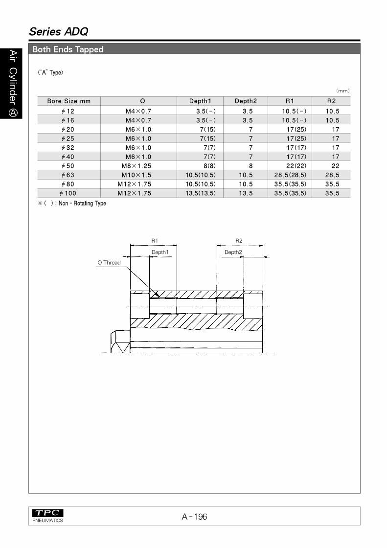
Both Ends Tapped
Series ADQ
<“A”Type>
※ ( ) : Non - Rotating Type
(mm)
ф12
ф16
ф20
ф25
ф32
ф40
ф50
ф63
ф80
ф100
M4×0.7
M4×0.7
M6×1.0
M6×1.0
M6×1.0
M6×1.0
M8×1.25
M10×1.5
M12×1.75
M12×1.75
3.5(‐)
3.5(‐)
7(15)
7(15)
7(7)
7(7)
8(8)
10.5(10.5)
10.5(10.5)
13.5(13.5)
3.5
3.5
7
7
7
7
8
10.5
10.5
13.5
10.5
10.5
17
17
17
17
22
28.5
35.5
35.5
10.5(‐)
10.5(‐)
17(25)
17(25)
17(17)
17(17)
22(22)
28.5(28.5)
35.5(35.5)
35.5(35.5)
Bore Size mm O Depth1 Depth2 R1 R2
R1
Depth1
O Thread
Depth2
R2
A-160~203 2002.7.18 7:1 PM 페이지196