8
Series Capacitor By-pass Switch
Series Capacitor By-pass Switch
2 Series Capacitor By-pass Switch |
Reactive power compensation Boosting transmission capacity
IntroductionABB implemented its first series compensation solutions in the 1950s. Since then, ABB has continued to develop and refine this technology. Today, our know-how and problem-solving capabilities help make us the world leader in effective power transmission.
Compensating inductive reactanceSeries compensation employs capacitors for compensating the inductive reactance of long lines. It is a highly effective and economical means of improving power transfer. Suit-able for both new and existing lines, series compensation increases power transfer capability by raising the transient stability limit as well as improving the voltage stability. Another important benefit is reduced transmission losses by optimizing the sharing of active power between parallel lines.
Extracting more power out of existing lines can eliminate the need to build new lines, which all adds up to reduced environ-mental impact, and significant cost and time savings.
By-pass systems for series capacitorsCommon for all installations in electrical power systems is that there are protective systems for overloads and faults, and that parts of the installations can be removed from service.
These are some of the reasons why series capacitors are equipped with a by-pass system. This by-pass system, which is connected in parallel with the capacitor bank, is designed to limit the voltage over the bank. The by-pass system thus has a protective function but is also used to switch the series capacitor in and out during planned measures, such as regu-lation of series capacitance as well as any maintenance on the series capacitor bank or other component parts.
There are a number of different solutions for by-pass systems.
The economy aspect is naturally important, and the grid’s configuration, its electrical properties and customer-specific requirements for protective functions come into play when choosing a by-pass system.
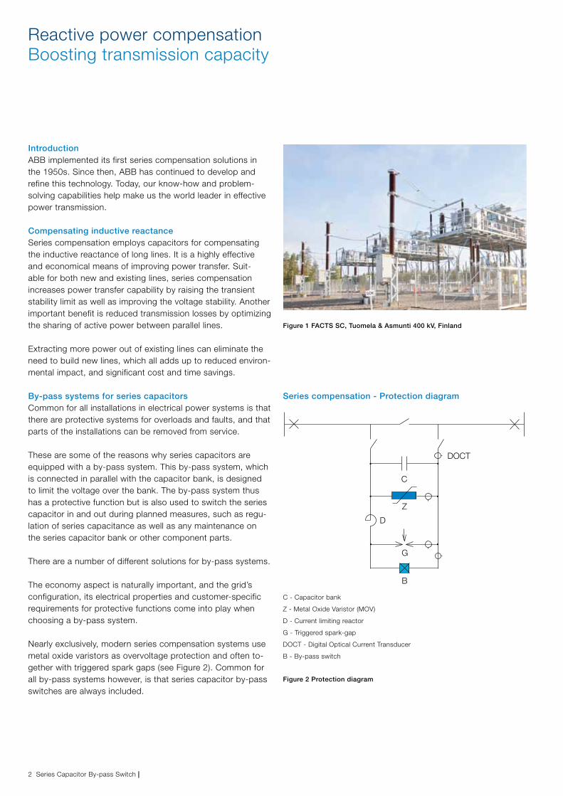
Nearly exclusively, modern series compensation systems use metal oxide varistors as overvoltage protection and often to-gether with triggered spark gaps (see Figure 2). Common for all by-pass systems however, is that series capacitor by-pass switches are always included.
Figure 2 Protection diagram
Series compensation - Protection diagram
C - Capacitor bank
Z - Metal Oxide Varistor (MOV)
D - Current limiting reactor
G - Triggered spark-gap
DOCT - Digital Optical Current Transducer
B - By-pass switch
Figure 1 FACTS SC, Tuomela & Asmunti 400 kV, Finland
C
Z
D
G
B
DOCT
| Series Capacitor By-pass Switch 3
The by-pass switch
Series capacitor by-pass switchesAlthough series capacitor by-pass switches sometimes utilize the same or similar design as that of a conventional circuit breaker, the application is completely different. The by-pass switch is part of the protective system of series capacitor banks, together with non-linear metal oxide varistors (MOV) and (if applicable) protective spark gaps, and is placed in parallel with the series capacitor bank.
The main purpose of the by-pass switch is for deliberately by-passing and inserting the series capacitor (planned operation) and for protective by-passing of the series capacitor in case of faults.
The standard operating sequence is C-0.3s-OC, which means that a conventional circuit breaker cannot be used as a by-pass switch due to this requirement.
Under normal service conditions when the series capacitor is connected in series with the overhead line, the by-pass switch is in the open position and always prepared to by-pass the series capacitor bank in case of faults or any planned operations.
The main stresses related to switching of by-pass switches are the following:a. By-passing of series capacitor
The by-pass switch must be able to by-pass the series capacitor bank when it is precharged to its protective level (limiting voltage of the overvoltage protector) and conse-quently withstand the associated inrush current from the capacitor bank superimposed on the line fault current.
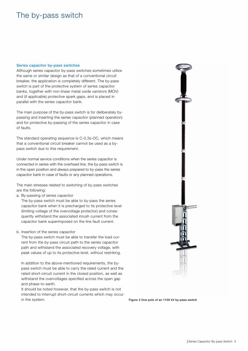
b. Insertion of the series capacitor The by-pass switch must be able to transfer the load cur-rent from the by-pass circuit path to the series capacitor path and withstand the associated recovery voltage, with peak values of up to its protective level, without restriking. In addition to the above-mentioned requirements, the by-pass switch must be able to carry the rated current and the rated short-circuit current in the closed position, as well as withstand the overvoltages specified across the open gap and phase-to-earth. It should be noted however, that the by-pass switch is not intended to interrupt short-circuit currents which may occur in the system. Figure 3 One pole of an 1100 kV by-pass switch
4 Series Capacitor By-pass Switch |
Explanations - definitions References
StandardsIEC 62271-109 is applicable for series capacitor by-pass switches.
It should be noted that ANSI/IEEE do not have a specific product standard for series capacitor by-pass switches, although IEEE 824 (Series Capacitor banks in power systems) specifies the major requirements for components included in the by-pass systems.
RatingsIn general, the main ratings as defined in IEC 62271-1 (e.g. rated current, rated short-time withstand current, rated fre-quency, etc.) are also applicable for by-pass switches.
Some additional ratings which are relevant for by-pass switches only and their application have been listed below:
Rated voltage to earthThe rated voltage to earth is the maximum system voltage for which the by-pass switch is designed.
Rated voltage across the open by-pass switchThe rated voltage (phase-to-phase) across the open by-pass switch shall be equal to or higher than the rated voltage of the capacitor bank (UN = XN x IN) multiplied by √3.
Rated by-pass making currentThe rated by-pass making current is the peak value of the current that the by-pass switch should be capable of making. The by-pass making current is the sum of the capacitor bank discharge current component and the power frequency fault current component. The frequency of the by-pass making current is associated with the frequency of the rated by-pass making current.
A typical value of the rated by-pass making current is in the range of 70 - 130 kA (peak).
Frequency of the rated by-pass making currentThe frequency of the rated by-pass making current is equal to the frequency of the capacitor bank discharge current frequency.
A typical value of the frequency of the rated by-pass making current is in the range of 500 – 1000 Hz.
Rated by-pass insertion currentThe rated by-pass insertion current is the RMS value of the power frequency current that the by-pass switch should be capable of transferring from the by-pass switch circuit path to the main series capacitor path.
Rated re-insertion voltage The rated re-insertion voltage is the peak value of the tran-sient recovery voltage that the by-pass switch should be capable of withstanding, without re-strike, after clearing the by-pass insertion current.
The rated re-insertion voltage should be equal to the protec-tive level of the series capacitor bank.
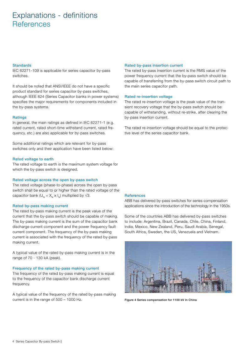
ReferencesABB has delivered by-pass switches for series compensation applications since the introduction of the technology in the 1950s.
Some of the countries ABB has delivered by-pass switches to include: Argentina, Brazil, Canada, Chile, China, Finland, India, Mexico, New Zealand, Peru, Saudi Arabia, Senegal, South Africa, Sweden, the US, Venezuela and Vietnam.
Figure 4 Series compensation for 1100 kV in China
| Series Capacitor By-pass Switch 5
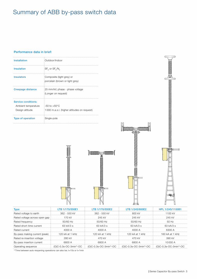
Summary of ABB by-pass switch data
Type LTB 1/170/550E1 LTB 1/170/550E2 LTB 1/245/800E2 HPL 1/245/1100B1
Rated voltage to earth 362 - 550 kV 362 - 550 kV 800 kV 1100 kV
Rated voltage across open gap 170 kV 245 kV 245 kV 245 kV
Rated frequency 50/60 Hz 50/60 Hz 50/60 Hz 50 Hz
Rated short-time current 63 kA/3 s 63 kA/3 s 63 kA/3 s 63 kA/3 s
Rated current 4000 A 4000 A 4000 A 6300 A
By-pass making current (peak) 120 kA at 1 kHz 120 kA at 1 kHz 120 kA at 1 kHz 160 kA at 1 kHz
Rated re-insertion voltage 280 kV 470 kV 470 kV 390 kV
By-pass insertion current 6800 A 6800 A 6800 A 10 000 A
Operating sequence (O)C-0.3s-OC-3min*)-OC (O)C-0.3s-OC-3min*)-OC (O)C-0.3s-OC-3min*)-OC (O)C-0.3s-OC-3min*)-OC
*) Time between auto-reopening operations can also be; t=15s or t=1min
Performance data in brief:
Installation Outdoor/Indoor
Insulation SF6 or SF6/N2
Insulators Composite (light grey) or
porcelain (brown or light grey)
Creepage distance 25 mm/kV, phase - phase voltage
(Longer on request)
Service conditions:
Ambient temperature
Design altitude
-50 to +50°C
1 000 m.a.s.l. (higher altitudes on request)
Type of operation Single-pole
6 Series Capacitor By-pass Switch |
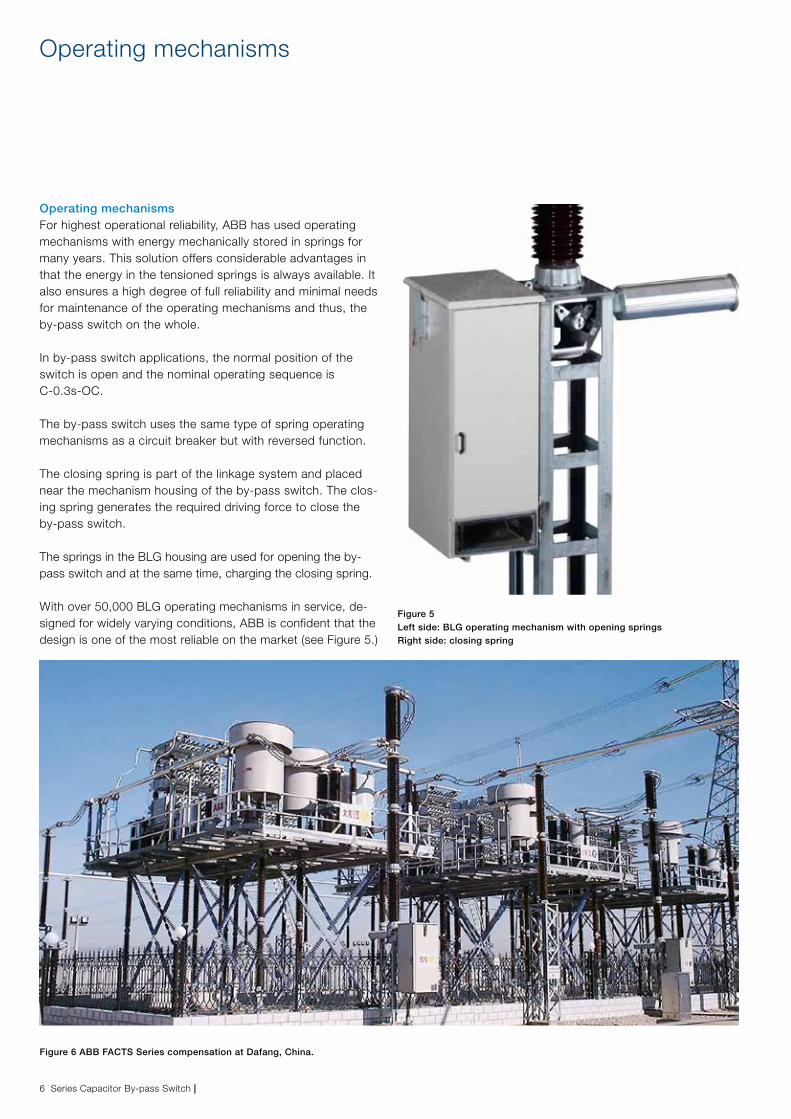
Operating mechanismsFor highest operational reliability, ABB has used operating mechanisms with energy mechanically stored in springs for many years. This solution offers considerable advantages in that the energy in the tensioned springs is always available. It also ensures a high degree of full reliability and minimal needs for maintenance of the operating mechanisms and thus, the by-pass switch on the whole.
In by-pass switch applications, the normal position of the switch is open and the nominal operating sequence is C-0.3s-OC.
The by-pass switch uses the same type of spring operating mechanisms as a circuit breaker but with reversed function.
The closing spring is part of the linkage system and placed near the mechanism housing of the by-pass switch. The clos-ing spring generates the required driving force to close the by-pass switch.
The springs in the BLG housing are used for opening the by-pass switch and at the same time, charging the closing spring.
With over 50,000 BLG operating mechanisms in service, de-signed for widely varying conditions, ABB is confident that the design is one of the most reliable on the market (see Figure 5.)
Figure 5 Left side: BLG operating mechanism with opening springs Right side: closing spring
Operating mechanisms
Figure 6 ABB FACTS Series compensation at Dafang, China.
| Series Capacitor By-pass Switch 7
Testing and Inquiry data
Type testsThe following tests are applicable for by-pass switches:
− 1. Dielectric tests − 2. Peak and short-time withstand current tests − 3. Mechanical operation tests − 4. Temperature rise tests − 5. By-pass making current tests − 6. Insertion current tests
As a minimum, the following information is required and can preferably be copied and sent along with your inquiry.
PROJECT DATA
End-customer
Name of project
Standard / Customer specification
Number of by-pass switches
Delivery time
TECHNICAL DATA
Rated voltage to earth
Rated voltage across open by-pass switch
Rated insulation level to earth
Rated insulation level across open by-pass switch
Rated frequency
Rated normal current
Rated short-time withstand current
Rated peak withstand current
Duration of short-circuit
Rated operating sequence
Rated by-pass making current
Frequency of the rated by-pass making current
By-pass discharge current
Damping of the by-pass discharge current
Rated by-pass insertion current
Rated reinsertion voltage
Mechanical endurance class
Rated supply voltage of auxiliary and control circuits
AMBIENT CONDITIONS
Ambient temperature (min. – max.)
Altitude (if higher than 1000 m.a.s.l.)
Seismic conditions
Environmental conditions (creepage distance)
Tests 1-4 are similar tests to those of conventional circuit breakers.
Tests 5-6 are specific tests to verify the requirements for by-passing and re-inserting the capacitor bank.
Note: Other tests defined for conventional circuit breakers, such as short-circuit breaking tests, short-line fault tests, out-of-phase switching tests, etc., are not applicable for by-pass switches
Contact us
Pub
licat
ion
1HS
M 9
543
22-1
2en,
Ser
ies
Cap
acito
r B
y-p
ass
Sw
itch,
Ed
ition
1,
2011
-12.ABB AB
High Voltage Products SE-771 80 LUDVIKA, SWEDEN Phone: +46 (0)240 78 20 00 E-mail: [email protected] www.abb.comwww.abb.com/highvoltage
©Copyright 2011 ABB. All rights reserved
NOTE: ABB AB is working continuously to improve
the products. We therefore reserve the right to
change designs, dimensions and data without prior
notice.


