אילן רן- מהנדסCarrier Israel Technologies Series Counter flow Design for increasing the Energy Efficiency of the Machinery Room תכנון טורי של צ' ילרים בעיבוי מים עם זרימת מי עיבוי מנוגדת לשם הגדלת היעילות האנרגטית של חדר המכונות כנס חשמל2017
Transcript
Carrier Israel Technologiesמהנדס -אילן רן
Series Counter flow Design for increasing the Energy Efficiency of the Machinery Room
בעיבוי מים עם זרימת מי עיבוי מנוגדת לשם הגדלת היעילות ילרים'צתכנון טורי של האנרגטית של חדר המכונות
2017כנס חשמל
Presenter
Presentation Notes
VFDs take advantage of Part Lift & Part Load with Speed Control
When two (2) or more chillers are connected in parallel, both chillers experience the same lift.
the lift each chiller experiences is approximately 51F.
Series Counterflow (SCF) Chillers
c. Water flow in the evaporator is opposite of the water flow in the condenser, a counterflow arrangement (opposite to each other)
Evaporator/ Cooler
Condenser
CompressorPressure
Reducing Device
95°F (35°C)85°F (30°C)
44° F (6.7°C)
Liquid Line
Hot Gas Discharge Line
Suction Line
Saturated Condensing Temp
(SCT)
(SST) Saturated Suction
Temp
Basic Refrigeration Cycle
4
54° F (12.2°C)
Enthalpy
Pres
sure
97F
77F
42F
Heat Rejection
SAT. LIQUID
SAT. VAPOR
Refrigerant Effect(Capacity)
Reduced Lift
97 F (36 C) / 120 PSI 77 F (25 C) / 85 PSI42 F (5.5 C) / 40 PSI -
Chilled Water in (12.2c)
Chilled Water out (6.7c)
AFFINITY LAWS
Presenter
Presentation Notes
Lift is saturated condensing temperature (SCT) minus saturated suction temperature (SST). SCT is dependent upon LEAVING condenser water temperature which is dependent upon ENTERING condenser water temperature and FLOW RATE. Saturated Suction Temperature is based off of LEAVING chilled water temperature. Note: VFDs on condenser pumps don’t make sense because they raise leaving condenser water temperature, therefore raise SCT and therefore raise Lift and therefore change compressor power. Note: Lowering chilled water temperature lowers the SCT and raises lift and therefore raises chiller compressor power.
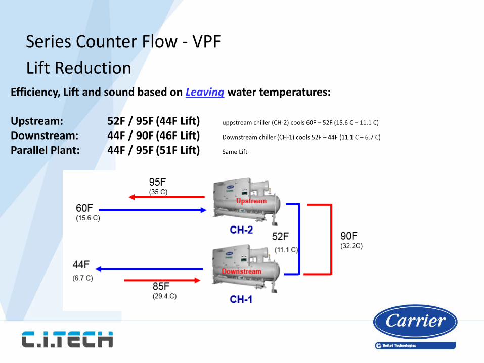
Series Counter Flow - VPFLift Reduction
Efficiency, Lift and sound based on Leaving water temperatures:
Upstream: 52F / 95F (44F Lift) uppstream chiller (CH-2) cools 60F – 52F (15.6 C – 11.1 C)
Downstream: 44F / 90F (46F Lift) Downstream chiller (CH-1) cools 52F – 44F (11.1 C – 6.7 C)
Parallel Plant: 44F / 95F (51F Lift) Same Lift
Maximize Efficiency with Series Counterflow (SCF)
• Up to 25 percent better full load efficiency than ASHRAE 90.1 2013 standards*
• Up to 47 percent better part load efficiency than ASHRAE 90.1 2013 standards*
• Up to 6 dbA quieter than parallel chillers.
*(2) 250 ton (879 kW) variable-speed 23XRV chillers in series counterflow arrangement
Series Counter-Flow Chilled Water System with Heat Recovery Chiller
1. The first stage of cooling is provided by the heat reclaim chiller.
Sequence of operation
2. On a call for cooling from the primary chilled water loop,3. The heat reclaim chiller provided the first stage of cooling
while providing a controlled source of hot water based onits HEAT set point temperature.
4. The heat reclaim chiller’s “low source protection” feature will ensure that chilled water is provided at a tem. that is not less than the cooling set point .
5. If additional cooling is needed to maintain temp., the series
counter-flow chiller plant would be energized.6. The heat reclaim chiller would continue to control the hot water temperature based on its HEAT set point
"Lift is based on leaving” (leaving condenser water temperature less leaving evaporator water temperature) Remember !!
Presenter
Presentation Notes
lower lift provided by smaller differences between the leaving chilled water temperature and the leaving condenser water temperature
Case Study 1
What would happen if
Typical SCF chiller plant arrangement
What would happen in the event that CH-2 (downstream) failed
Typical SCF chiller plant arrangement
It is for such an event that optimal series counterflow design typically includes an additional parallel chiller.
The isolation valves of CH-2 (downstream) would close, eliminating it from the system.
In addition,the isolation valves of CH-3 open, allowing CH-1 and CH-3 to provide cooling for the given application.
Unlike the series configuration where CH-1 and CH-2 were both provided with full pump flow, the parallel configuration causes CH-1 and CH-3 to each receive half of the available pump flow.
Typical SCF chiller plant arrangement
The parallel chillers are provided with half of the condenser flow as a result of a pump malfunction.
Lift variations for different chiller configurations
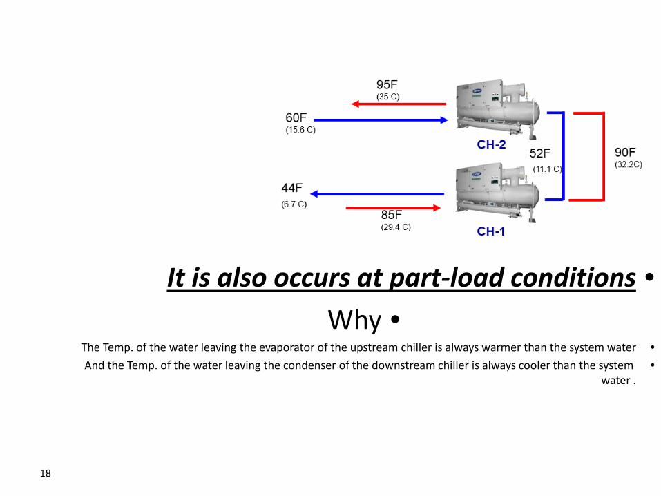
•The Temp. of the water leaving the evaporator of the upstream chiller is always warmer than the system water•And the Temp. of the water leaving the condenser of the downstream chiller is always cooler than the system