40
INSTRUCTION MANUAL P2001406 Rev E Series e-1510

INSTRUCTION MANUALP2001406 Rev E
Series e-1510


Table of Contents
1 Introduction and Safety..............................................................................................................31.1 Introduction.......................................................................................................................... 31.2 Safety..................................................................................................................................... 3
1.2.1 Safety message levels...................................................................................................31.2.2 Safety instruction decals.............................................................................................. 41.2.3 User safety......................................................................................................................51.2.4 Protecting the environment.........................................................................................7
2 Transportation and Storage...................................................................................................... 82.1 Examine the delivery........................................................................................................... 8
2.1.1 Examine the package................................................................................................... 82.1.2 Examine the unit............................................................................................................8
2.2 Safe handling requirements............................................................................................... 82.3 Storage requirements..........................................................................................................9
3 Product Description................................................................................................................. 103.1 General description...........................................................................................................103.2 Operational specifications................................................................................................10
4 Installation................................................................................................................................. 124.1 Preinstallation.....................................................................................................................12
4.1.1 Pump location guidelines..........................................................................................124.1.2 Foundation requirements..........................................................................................134.1.3 Piping checklist........................................................................................................... 134.1.4 Pump insulation checklist.......................................................................................... 144.1.5 Typical installation...................................................................................................... 154.1.6 Special installation......................................................................................................15
4.2 Install the pump, driver, and coupling............................................................................154.3 Level the base on a concrete foundation ...................................................................... 164.4 Grout the baseplate...........................................................................................................164.5 Pump-to-driver alignment................................................................................................ 174.6 Alignment checks.............................................................................................................. 174.7 Align a standard sleeve type coupling (black rubber sleeve)......................................174.8 Additional alignment instructions....................................................................................19
5 Commissioning, Startup, Operation, and Shutdown.......................................................... 205.1 Preparation for startup...................................................................................................... 20
5.1.1 Check the rotation...................................................................................................... 205.2 Start the pump....................................................................................................................215.3 Pump operation precautions............................................................................................215.4 Shut down the pump.........................................................................................................225.5 Make the final alignment of the pump and driver.........................................................225.6 Note on the packed pump operation............................................................................. 22
6 Maintenance..............................................................................................................................246.1 Bearing maintenance........................................................................................................ 24
6.1.1 Regrease the grease-lubricated bearings............................................................... 246.1.2 Lubricating grease requirements............................................................................. 24
6.2 Disassembly........................................................................................................................256.2.1 Disassembly precautions...........................................................................................25
Table of Contents
Series e-1510 INSTRUCTION MANUAL 1

6.2.2 Drain the pump...........................................................................................................256.2.3 Remove the hex coupling guard.............................................................................. 256.2.4 Remove the coupling................................................................................................. 266.2.5 Remove the bearing frame and impeller assembly .............................................. 266.2.6 Remove the impeller.................................................................................................. 276.2.7 Remove the mechanical seal (e-1510 and e-1510-F).............................................276.2.8 Remove the seal or packing rings (e-1510-S and e-1510-PF)...............................27
6.3 Pre-assembly inspections................................................................................................. 276.3.1 Replacement guidelines............................................................................................ 286.3.2 Shaft and sleeve inspection.......................................................................................286.3.3 Bearing frame inspection...........................................................................................286.3.4 Impeller trimming guidelines....................................................................................28
6.4 Reassembly.........................................................................................................................296.4.1 Seal assembly..............................................................................................................296.4.2 Impeller installation.................................................................................................... 316.4.3 Assemble the packed stuffing box (e-1510-PF) .....................................................326.4.4 Reinstall the bearing frame and impeller assembly .............................................. 326.4.5 Install the hex coupling guard...................................................................................336.4.6 Torque values..............................................................................................................336.4.7 Dealer servicing ......................................................................................................... 34
7 Product warranty...................................................................................................................... 35
Table of Contents
2 Series e-1510 INSTRUCTION MANUAL

1 Introduction and Safety1.1 IntroductionPurpose of this manual
The purpose of this manual is to provide necessary information for:
• Installation• Operation• Maintenance
CAUTION:
Read this manual carefully before installing and using the product. Improper use of theproduct can cause personal injury and damage to property, and may void the warranty.
NOTICE:
Save this manual for future reference, and keep it readily available at the location of theunit.
1.2 SafetyWARNING:
• The operator must be aware of safety precautions to prevent physical injury.• Operating, installing, or maintaining the unit in any way that is not covered in this
manual could cause death, serious personal injury, or damage to the equipment. Thisincludes any modification to the equipment or use of parts not provided by Xylem. Ifthere is a question regarding the intended use of the equipment, please contact aXylem representative before proceeding.
• Do not change the service application without the approval of an authorized Xylemrepresentative.
CAUTION:
You must observe the instructions contained in this manual. Failure to do so could resultin physical injury, damage, or delays.
1.2.1 Safety message levels
About safety messages
It is extremely important that you read, understand, and follow the safety messages andregulations carefully before handling the product. They are published to help preventthese hazards:
• Personal accidents and health problems• Damage to the product• Product malfunction
Definitions
Safety message level Indication
DANGER:
A hazardous situation which, if not avoided, will result indeath or serious injury
1 Introduction and Safety
Series e-1510 INSTRUCTION MANUAL 3

Safety message level Indication
WARNING:
A hazardous situation which, if not avoided, could resultin death or serious injury
CAUTION:
A hazardous situation which, if not avoided, could resultin minor or moderate injury
Electrical Hazard:
The possibility of electrical risks if instructions are notfollowed in a proper manner
NOTICE:
• A potential situation which, if not avoided, couldresult in undesirable conditions
• A practice not related to personal injury
1.2.2 Safety instruction decals
Alert symbol
This safety alert symbol is used in manuals and on the safety instruction decals on the pumpto draw attention to safety-related instructions.When used, the safety alert symbol means that failure to follow the instructions may result ina safety hazard.
Decals
Make sure your pump has these safety instruction decals and that they are located as thisfigure shows. If the decals are missing or illegible, contact your local sales and servicerepresentative for a replacement.
1 Introduction and Safety
4 Series e-1510 INSTRUCTION MANUAL

P70642
P70643
(2) Required(1 Each Side)
AlternateLocation
P2002458
P70820
DO NOT RUN PUMP DRY, SEALDAMAGE MAY OCCUR.INSPECT PUMP SEALREGULARLY FOR LEAKS,REPLACE AS REQUIRED.LUBRICATION REQUIREMENTSCONSULT MANUALS.PUMP: POLYUREA-BASED GREASEFAILURE TO FOLLOWINSTRUCTIONS COULDRESULT IN INJURY ORPROPERTY DAMAGE.
Make sure that all safety instruction decals are always clearly visible and readable.
1.2.3 User safety
General safety rules
These safety rules apply:
• Always keep the work area clean.• Pay attention to the risks presented by gas and vapors in the work area.• Avoid all electrical dangers. Pay attention to the risks of electric shock or arc flash
hazards.• Always bear in mind the risk of drowning, electrical accidents, and burn injuries.
Safety equipment
Use safety equipment according to the company regulations. Use this safety equipmentwithin the work area:
• Hard hat• Safety goggles, preferably with side shields• Protective shoes• Protective gloves• Gas mask• Hearing protection• First-aid kit• Safety devices
1 Introduction and Safety
Series e-1510 INSTRUCTION MANUAL 5

NOTICE:
Never operate a unit unless safety devices are installed. Also see specific informationabout safety devices in other chapters of this manual.
Electrical connections
Electrical connections must be made by certified electricians in compliance with allinternational, national, state, and local regulations. For more information aboutrequirements, see sections dealing specifically with electrical connections.
Precautions before work
Observe these safety precautions before you work with the product or are in connectionwith the product:
• Provide a suitable barrier around the work area, for example, a guard rail.• Make sure that all safety guards are in place and secure.• Make sure that you have a clear path of retreat.• Make sure that the product cannot roll or fall over and injure people or damage
property.• Make sure that the lifting equipment is in good condition.• Use a lifting harness, a safety line, and a breathing device as required.• Allow all system and pump components to cool before you handle them.• Make sure that the product has been thoroughly cleaned.• Disconnect and lock out power before you service the pump.• Check the explosion risk before you weld or use electric hand tools.
Precautions during work
Observe these safety precautions when you work with the product or are in connectionwith the product:
• Never work alone.• Always wear protective clothing and hand protection.• Stay clear of suspended loads.• Always lift the product by its lifting device.• Beware of the risk of a sudden start if the product is used with an automatic level
control.• Beware of the starting jerk, which can be powerful.• Rinse the components in water after you disassemble the pump.• Do not exceed the maximum working pressure of the pump.• Do not open any vent or drain valve or remove any plugs while the system is
pressurized. Make sure that the pump is isolated from the system and that pressure isrelieved before you disassemble the pump, remove plugs, or disconnect piping.
• Never operate a pump without a properly installed coupling guard.
1.2.3.1 Wash the skin and eyesFollow these procedures for chemicals or hazardous fluids that have come into contactwith your eyes or your skin:
Condition Action
Chemicals or hazardous fluids ineyes
1. Hold your eyelids apart forcibly with your fingers.2. Rinse the eyes with eyewash or running water for at least 15 minutes.3. Seek medical attention.
Chemicals or hazardous fluids onskin
1. Remove contaminated clothing.2. Wash the skin with soap and water for at least 1 minute.3. Seek medical attention, if necessary.
1 Introduction and Safety
6 Series e-1510 INSTRUCTION MANUAL

1.2.4 Protecting the environment
Emissions and waste disposal
Observe the local regulations and codes regarding:
• Reporting of emissions to the appropriate authorities• Sorting, recycling and disposal of solid or liquid waste• Clean-up of spills
Exceptional sites
CAUTION: Radiation Hazard
Do NOT send the product to Xylem if it has been exposed to nuclear radiation, unlessXylem has been informed and appropriate actions have been agreed upon.
Recycling guidelines
Always follow local laws and regulations regarding recycling.
1 Introduction and Safety
Series e-1510 INSTRUCTION MANUAL 7
2 Transportation and Storage2.1 Examine the delivery2.1.1 Examine the package
1. Examine the package for damaged or missing items upon delivery.
2. Record any damaged or missing items on the receipt and freight bill.
3. If anything is out of order, then file a claim with the shipping company.
If the product has been picked up at a distributor, make a claim directly to thedistributor.
2.1.2 Examine the unit1. Remove packing materials from the product.
Dispose of all packing materials in accordance with local regulations.
2. To determine whether any parts have been damaged or are missing, examine theproduct.
3. If applicable, unfasten the product by removing any screws, bolts, or straps.
Use care around nails and straps.
4. If there is any issue, then contact a sales representative.
2.2 Safe handling requirementsWARNING:
• Personal protective equipment should be worn when handling this equipment.• Transportation & installation of this equipment should only be performed by qualified
personnel.• A professional rigging company should be consulted before lifting the pump
assembly.• Only use properly sized, certified lifting equipment & lifting devices, including slings,
suitably rated for the weights to be lifted.• Slings, when used, must be of identical materials to avoid differences in stretch rates.• Do not use lifting devices that are frayed, kinked, unmarked, or worn.• Lifting eyebolts fitted on single components of the assembly (pump or motor) must not
be used to lift the complete assembly.• Failure to observe these instructions could result in equipment or property damage,
serious injury, or death.
The pump assembly can arrive in a variety of ways. It can be shipped as pump end only(bare pump), pump less motor, or pump, motor, & baseplate. Use the followingrecommended ways of handling e-1510 pump assemblies. The pump assembly shouldremain horizontal during transport and lifting.
Table 1: Lifting methods
Pump type Lifting method
A bare pump without liftinghandles
Use a suitable sling attached properly to solid points like the casing, the flanges, orthe frames.
2 Transportation and Storage
8 Series e-1510 INSTRUCTION MANUAL

Pump type Lifting method
A base-mounted pump. Lifting the pump less motor or the pump, motor, & baseplate should be done byusing lifting lugs provided on the baseplate, or by utilizing a forklift under theentire unit. Always take extra precaution to ensure the weight is balanced & equallydistributed across both forks. When the baseplate of the assembly is structuralchannel construction, the pump and base plate should be set in place first. Themotor should then be separately lifted & mounted to the unit.
Examples
Figure 1: Example of a proper lifting method using lifting lugs
Figure 2: Lift using a forklift
2.3 Storage requirementsIf the unit will not to be installed and put into operation immediately upon arrival at thesite, or for an extended shutdown after the unit is in operation, the following requirementsfor short-term storage apply:
• Store in a covered and dry location.• Store the unit free from excessive cold or heat (below 32°F and above 110°F), dirt, and
vibration.• Rotate the shaft by hand several times (10–15 turns) at least every 30 days.
For initial storage longer than three months, or for pump shut down after being inoperation longer than three months, contact your local sales and service representativefor long-term storage guidelines.
2 Transportation and Storage
Series e-1510 INSTRUCTION MANUAL 9
3 Product Description3.1 General descriptionDescription
The pump is a centrifugal, frame-mounted pump. The following pump features make iteasy to install, operate, and service:
• High efficiency• Rugged stainless steel-fitted construction• Foot-mounted volute with back pullout bearing frame• Center drop-out coupling• Regreasable bearings
Intended applications
WARNING:
This product can expose you to chemicals including Lead, which is known to the State ofCalifornia to cause cancer and birth defects or other reproductive harm. For moreinformation go to: www.P65Warnings.ca.gov.
The pump is intended for use with these pumped fluids:
• Unheated domestic and fresh water• Boiler feed water• Condensate• Hydronic cooling or heating• Benign liquids• Pressure boosting• General liquid transfer
Rotation
Pump rotation is clockwise when viewed from the back of the motor. An arrow is alsolocated on the pump to show the direction of rotation.
3.2 Operational specificationsMechanical seal specifications
Seal type/Parameter
Standard seal,BUNA/Carbon/Ceramic
Optional seal,EPR/Carbon /TungstenCarbide
Optional seal,FKM/Carbon /Ceramic
Optional seal,EPR/SiliconCarbide/SiliconCarbide
Optional seal,EPR/Carbon /TungstenCarbide withexternalflush1,3,4
Packing2
Operatingtemperaturerange, °F (°C)
-20 to 225 (-29to 107)
-20 to 250 (-29to 121)
-10 to 225 (-23to 107)
-20 to 250 (-29to 121)
-20 to 250 (-29to 121)
0 to 200 (-18to 93)
pH range limits 7.0 to 9.0 7.0 to 11.0 7.0 to 9.0 7.0 to 12.5 7.0 to 9.0 7.0 to 9.0
Resistance todissolvedsolids
Low Low-Medium Low Medium-High Low-Medium Medium
Maximumglycol/waterconcentration
50/50% 50/50% 50/50% 60/40% 50/50% Notrecommended
Table notes
3 Product Description
10 Series e-1510 INSTRUCTION MANUAL

1. An external flush is required on low pressure systems that contain a high concentrationof abrasives.
2. Use packing on open or closed systems which require a large amount of makeupwater, as well as systems that are subjected to a wide variety of chemical conditionsand solids buildup.
3. For operating temperatures above 250°F, a cooled flush is required and isrecommended for temperatures above 225°F for optimum seal life. On closedsystems, cooling is accomplished by inserting a small heat exchanger in the flush lineto cool the seal flushing fluid.
4. Flush-line filters and sediment separators are available on request.
3 Product Description
Series e-1510 INSTRUCTION MANUAL 11
4 Installation4.1 PreinstallationPrecautions
WARNING:
• When installing in a potentially explosive environment, make sure that the motor isproperly certified.
• You must ground (earth) all electrical equipment. This applies to the pump equipment,the driver, and any monitoring equipment. Test the ground (earth) lead to verify that itis connected correctly.
NOTICE:
Supervision by an authorized Xylem representative is recommended to ensure properinstallation. Failure to do so may result in equipment damage or decreased performance.
Evaluate the installation in order to determine that the Net Positive Suction Head Available(NPSHA) meets or exceeds the Net Positive Suction Head Required (NPSHR), as stated bythe pump performance curve.
4.1.1 Pump location guidelines
WARNING:
Assembled units and their components are heavy. Failure to properly lift and support thisequipment can result in serious physical injury and/or equipment damage. Lift equipmentonly at the specifically identified lifting points. Lifting devices such as eyebolts, slings, andspreaders must be rated, selected, and used for the entire load being lifted.
Guideline Explanation/comment
Keep the pump as close to the liquid source aspractically possible.
This minimizes the friction loss and keeps the suction pipingas short as possible.
Make sure that the space around the pump issufficient.
This facilitates ventilation, inspection, maintenance, andservice.
If you require lifting equipment such as a hoist ortackle, make sure that there is enough space abovethe pump.
This makes it easier to properly use the lifting equipment andsafely remove and relocate the components to a safe location.
Protect the unit from weather and water damage dueto rain, flooding, and freezing temperatures.
This is applicable if nothing else is specified.
Do not install and operate the equipment in closedsystems unless the system is constructed withproperly-sized safety devices and control devices.
Acceptable devices:• Pressure relief valves• Compression tanks• Pressure controls• Temperature controls• Flow controls
If the system does not include these devices, consult theengineer or architect in charge before you operate the pump.
Take into consideration the occurrence of unwantednoise and vibration.
The best pump location for noise and vibration absorption ison a concrete floor with subsoil underneath.
If the pump location is overhead, undertake specialprecautions to reduce possible noise transmission.
Consider a consultation with a noise specialist.
When possible, locate the pump below the fluidlevel.
This facilitates priming, ensures a steady flow of liquid, andprovides a positive suction head on the pump.
4 Installation
12 Series e-1510 INSTRUCTION MANUAL
4.1.2 Foundation requirements
Requirements
• The foundation must be able to absorb any type of vibration and form a permanent,rigid support for the unit.
• The foundation must weigh at least 2-1/2 times the weight of the pump unit.• Provide a flat, substantial concrete foundation in order to prevent strain and distortion
when you tighten the foundation bolts.• Anchor bolts are preferred installed vertically, but when expansion type or chemically
set anchors are installed at an angle through the base mounting holes, beveledwashers with matching angles shall be used under the anchor bolt nuts.
• Tie the concrete pad in with the finished floor.• Use foundation bolts and larger pipe sleeves to give room for final bolt location.
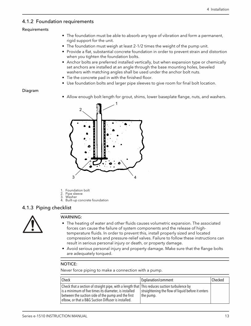
Diagram
• Allow enough bolt length for grout, shims, lower baseplate flange, nuts, and washers.
2
3
1
4
1. Foundation bolt2. Pipe sleeve3. Washer4. Built-up concrete foundation
4.1.3 Piping checklist
WARNING:
• The heating of water and other fluids causes volumetric expansion. The associatedforces can cause the failure of system components and the release of high-temperature fluids. In order to prevent this, install properly sized and locatedcompression tanks and pressure-relief valves. Failure to follow these instructions canresult in serious personal injury or death, or property damage.
• Avoid serious personal injury and property damage. Make sure that the flange boltsare adequately torqued.
NOTICE:
Never force piping to make a connection with a pump.
Check Explanation/comment Checked
Check that a section of straight pipe, with a length thatis a minimum of five times its diameter, is installedbetween the suction side of the pump and the firstelbow, or that a B&G Suction Diffuser is installed.
This reduces suction turbulence bystraightening the flow of liquid before it entersthe pump.
4 Installation
Series e-1510 INSTRUCTION MANUAL 13
Check Explanation/comment Checked
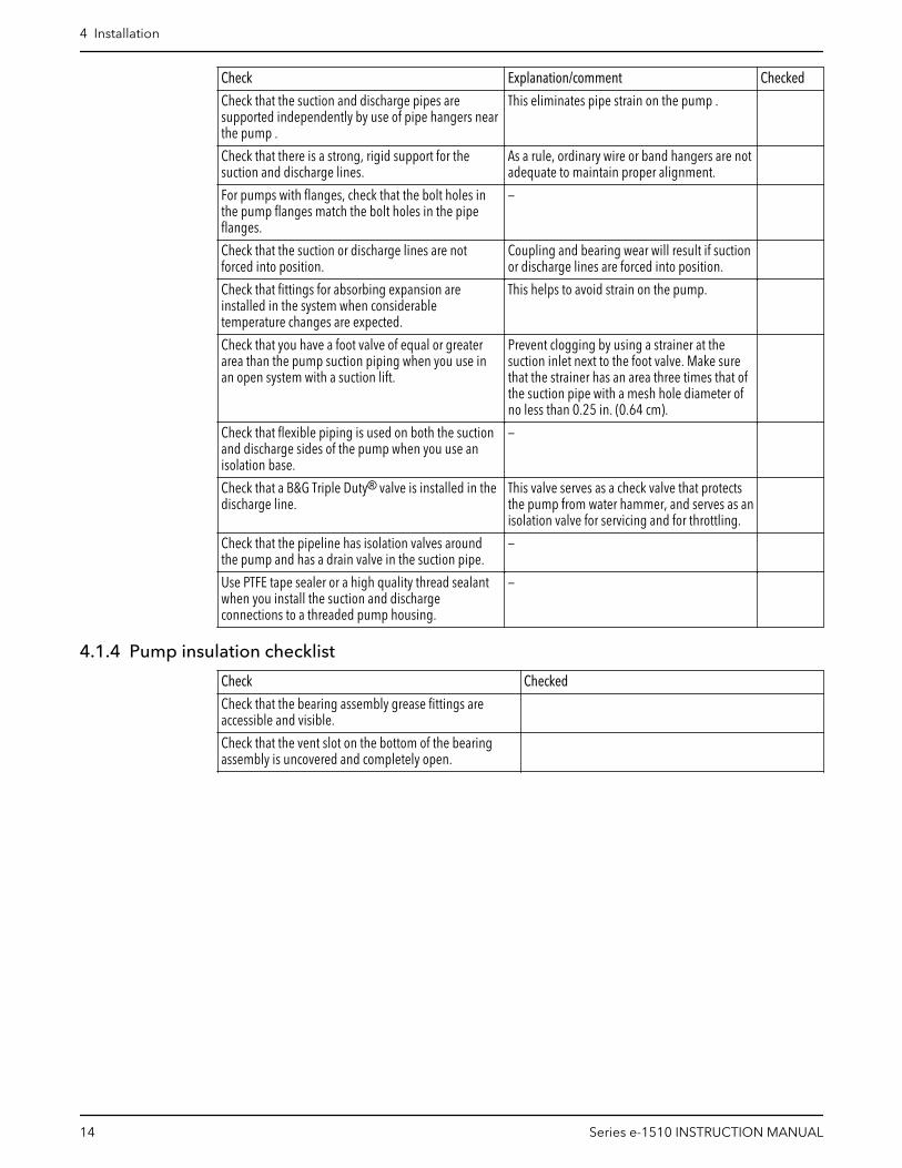
Check that the suction and discharge pipes aresupported independently by use of pipe hangers nearthe pump .
This eliminates pipe strain on the pump .
Check that there is a strong, rigid support for thesuction and discharge lines.
As a rule, ordinary wire or band hangers are notadequate to maintain proper alignment.
For pumps with flanges, check that the bolt holes inthe pump flanges match the bolt holes in the pipeflanges.
—
Check that the suction or discharge lines are notforced into position.
Coupling and bearing wear will result if suctionor discharge lines are forced into position.
Check that fittings for absorbing expansion areinstalled in the system when considerabletemperature changes are expected.
This helps to avoid strain on the pump.
Check that you have a foot valve of equal or greaterarea than the pump suction piping when you use inan open system with a suction lift.
Prevent clogging by using a strainer at thesuction inlet next to the foot valve. Make surethat the strainer has an area three times that ofthe suction pipe with a mesh hole diameter ofno less than 0.25 in. (0.64 cm).
Check that flexible piping is used on both the suctionand discharge sides of the pump when you use anisolation base.
—
Check that a B&G Triple Duty® valve is installed in thedischarge line.
This valve serves as a check valve that protectsthe pump from water hammer, and serves as anisolation valve for servicing and for throttling.
Check that the pipeline has isolation valves aroundthe pump and has a drain valve in the suction pipe.
—
Use PTFE tape sealer or a high quality thread sealantwhen you install the suction and dischargeconnections to a threaded pump housing.
—
4.1.4 Pump insulation checklist
Check Checked
Check that the bearing assembly grease fittings areaccessible and visible.
Check that the vent slot on the bottom of the bearingassembly is uncovered and completely open.
4 Installation
14 Series e-1510 INSTRUCTION MANUAL

4.1.5 Typical installation
4
5
67
8
10
9
1
2
3
1112
13
14
1. Expansion tank2. B&G Rolairtrol® air separator3. Supply to system4. TPV Tank Purge Valve5. B&G Triple Duty® valve6. B&G Series e-1510 Pump7. B&G Suction Diffuser8. Isolation valve9. Pipe from boiler, chiller, or converter10.Cold water supply11.B&G Pressure Reducing Valve12.B&G Model 107A — High capacity vent13.B&G #7 or #87 Air Vent14.Drain valve
4.1.6 Special installation
Installation with suction diffuser and triple-duty valve
Do not install and operate triple-duty valves and suction diffusers in closed systems unlessthe system is designed with these safety and control devices:
• Pressure relief valves• Expansion tank(s)• Pressure controlling equipment• Temperature controlling equipment• Flow controlling equipment
Check that the control and safety devices have these characteristics:
• Properly sized for their purpose• Placed correctly in the system before putting the system into operation
Installation with isolation base
When using an isolation base, flexible piping should be used on both suction anddischarge sides to reduce the strain on the flanges.
4.2 Install the pump, driver, and couplingPerform these steps only if the unit was not installed at the factory.
4 Installation
Series e-1510 INSTRUCTION MANUAL 15
1. Mount and fasten the pump on the baseplate. Use applicable bolts. Center pump onbaseplate.
2. Mount the driver on the baseplate. Use applicable bolts and hand tighten.
3. Install the coupling.
See the installation instructions from the coupling manufacturer.
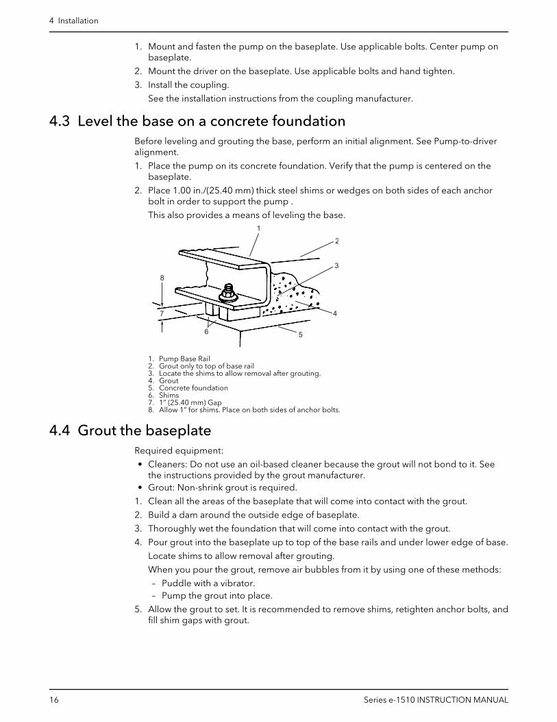
4.3 Level the base on a concrete foundationBefore leveling and grouting the base, perform an initial alignment. See Pump-to-driveralignment.
1. Place the pump on its concrete foundation. Verify that the pump is centered on thebaseplate.
2. Place 1.00 in./(25.40 mm) thick steel shims or wedges on both sides of each anchorbolt in order to support the pump .
This also provides a means of leveling the base.
4
1
5
2
3
6
7
8
1. Pump Base Rail2. Grout only to top of base rail3. Locate the shims to allow removal after grouting.4. Grout5. Concrete foundation6. Shims7. 1” (25.40 mm) Gap8. Allow 1” for shims. Place on both sides of anchor bolts.
4.4 Grout the baseplateRequired equipment:
• Cleaners: Do not use an oil-based cleaner because the grout will not bond to it. Seethe instructions provided by the grout manufacturer.
• Grout: Non-shrink grout is required.
1. Clean all the areas of the baseplate that will come into contact with the grout.
2. Build a dam around the outside edge of baseplate.
3. Thoroughly wet the foundation that will come into contact with the grout.
4. Pour grout into the baseplate up to top of the base rails and under lower edge of base.
Locate shims to allow removal after grouting.
When you pour the grout, remove air bubbles from it by using one of these methods:
– Puddle with a vibrator.– Pump the grout into place.
5. Allow the grout to set. It is recommended to remove shims, retighten anchor bolts, andfill shim gaps with grout.
4 Installation
16 Series e-1510 INSTRUCTION MANUAL
4.5 Pump-to-driver alignmentPrecautions
WARNING:
• Follow shaft alignment procedures in order to prevent catastrophic failure of drivecomponents or unintended contact of rotating parts. Follow the coupling installationand operation procedures from the coupling manufacturer.
• Always disconnect and lock out power to the driver before you perform any installationor maintenance tasks. Failure to disconnect and lock out driver power will result inserious physical injury.
NOTICE:
Proper alignment is the responsibility of the installer and the user of the unit. Check thealignment of frame-mounted units before you operate the unit. Failure to do so can resultin equipment damage or decreased performance.
4.6 Alignment checksWhen to perform alignment checks
You must perform alignment checks under these circumstances:
• The process temperature changes.• The piping changes.• The pump has been serviced.
Types of alignment checks
Type of check When it is used
Initial alignment (cold alignment)check
Prior to operation when the pump and the driver are at ambienttemperature.
Final alignment (hot alignment)check
After operation when the pump and the driver are at operating temperature.
Initial alignment (cold alignment) checks
When Why
After you connect the piping This ensures that pipe strains have not altered the alignment.If changes have occurred, you must alter the piping to remove pipe strains onthe pump flanges.
Final alignment (hot alignment) checks
When Why
After the first run This ensures correct alignment when both the pump and the driver are atoperating temperature.
Periodically This follows the plant operating procedures.
4.7 Align a standard sleeve type coupling (black rubber sleeve)WARNING:
Always disconnect and lock out power to the driver before you perform any installation ormaintenance tasks. Failure to disconnect and lock out driver power will result in seriousphysical injury.
4 Installation
Series e-1510 INSTRUCTION MANUAL 17

NOTICE:
• Do not rotate the coupler to make adjustments. This may result in equipment damage.• Do not move or shim the driver unless you need to make adjustments. This may result
in decreased performance.
Make sure you have the following before you start this procedure:
• A micrometer or a caliper• A maximum 1/64 in. (0.397 mm) end clearance between the sleeve and the two
coupling halves
1. Check for angular misalignment:
a) Measure from the outside face of one flange to the outside face of the oppositeflange at four points 90° apart. Use the micrometer or the caliper.
The maximum permitted mis-alignment value is 1/64 in. (0.397 mm) per inch of thecoupling hub radius.
1
1. Distances Across Coupling Flanges Should Be Equal (check 4 places)
Figure 3: Example of angular misalignment
b) Move or shim the drive unit, if necessary, until the permitted reading value isobtained.
2. Check for parallel misalignment:
a) Put a straight edge across one coupling half.b) Measure the gap between the straight edge and the opposite coupling half. Use
the micrometer or the caliper.
A gap of maximum 1/64 in. (0.397 mm) is permitted.
4 Installation
18 Series e-1510 INSTRUCTION MANUAL

1
2
1. Amount of Parallel Misalignment2. Straight Edge
Figure 4: Example of parallel misalignment
c) Move or shim the drive unit, if necessary, until the permitted reading value isobtained.
When the procedure is complete, both the angular and parallel alignment must meet thepermitted tolerances.
4.8 Additional alignment instructions• When couplings other than the standard sleeve type are used, refer to the coupling
manufacturer’s alignment instructions.• Alternate alignment methods, such as dial indicator or laser alignment can be used to
achieve the coupling alignment requirements.
4 Installation
Series e-1510 INSTRUCTION MANUAL 19

5 Commissioning, Startup,Operation, and Shutdown5.1 Preparation for startup
WARNING:
• Failure to follow these precautions before you start the unit will lead to seriouspersonal injury and equipment failure.
• Do not run the pump dry.• Do NOT operate the pump at zero flow or with suction and discharge valves closed.
These conditions can create an explosive hazard due to vaporization of pumped fluidand can quickly lead to pump failure and physical injury.
• Always disconnect and lock out power to the driver before you perform any installationor maintenance tasks. Failure to disconnect and lock out driver power will result inserious physical injury.
• Operating the pump in reverse rotation can result in the contact of metal parts, heatgeneration, and breach of containment.
NOTICE:
• Verify the driver settings before you start any pump.• Make sure that the warm-up rate does not exceed 2.5°F (1.4°C) per minute.
You must follow these precautions before you start the pump:
• Flush and clear the system thoroughly to remove dirt or debris in the pipe system inorder to prevent premature failure at initial startup.
• Bring variable-speed drivers to the rated speed as quickly as possible.• If temperatures of the pumped fluid will exceed 200°F (93°C), then warm up the pump
prior to operation. Circulate a small amount of fluid through the pump until the casingtemperature is within 100°F (38°C) of the fluid temperature.
At initial startup, do not adjust the variable-speed drivers or check for speed governor orover-speed trip settings while the variable-speed driver is coupled to the pump. If thesettings have not been verified, then uncouple the unit and refer to instructions suppliedby the driver manufacturer.
5.1.1 Check the rotation
WARNING:
• Operating the pump in reverse rotation can result in the contact of metal parts, heatgeneration, and breach of containment.
• Always disconnect and lock out power to the driver before you perform any installationor maintenance tasks. Failure to disconnect and lock out driver power will result inserious physical injury.
1. Lock out power to the driver.
2. Make sure that the coupling hubs are fastened securely to the shafts.
3. Unlock power to the driver.
4. Make sure that everyone is clear, and then jog the driver long enough to determinethat the direction of rotation corresponds to the arrow on the pump.
5. Lock out power to the driver.
5 Commissioning, Startup, Operation, and Shutdown
20 Series e-1510 INSTRUCTION MANUAL

5.2 Start the pumpCAUTION:
• Immediately observe the pressure gauges. If discharge pressure is not quicklyattained, stop the driver, reprime, and attempt to restart the pump.
• Observe the pump for vibration levels, bearing temperature, and excessive noise. Ifnormal levels are exceeded, shut down the pump and resolve the issue.
Before you start the pump, you must perform these tasks:
• Open the suction valve.• Open any recirculation or cooling lines.
1. Fully close or partially open the discharge valve, depending on system conditions.
2. Start the driver.
3. Slowly open the discharge valve until the pump reaches the desired flow.
4. Immediately check the pressure gauge to ensure that the pump quickly reaches thecorrect discharge pressure.
5. If the pump fails to reach the correct pressure, perform these steps:
a) Stop the driver.b) Prime the pump again.c) Restart the driver.
6. Monitor the pump while it is operating:
a) Check the pump for bearing temperature, excessive vibration, and noise.b) If the pump exceeds normal levels, then shut down the pump immediately and
correct the problem.
7. Repeat steps 5 and 6 until the pump runs properly.
5.3 Pump operation precautionsGeneral considerations
CAUTION:
• Vary the capacity with the regulating valve in the discharge line. Never throttle the flowfrom the suction side since this can result in decreased performance, unexpected heatgeneration, and equipment damage.
• Do not overload the driver. Driver overload can result in unexpected heat generationand equipment damage. The driver can overload in these circumstances:
– The specific gravity of the pumped fluid is greater than expected.– The pumped fluid exceeds the rated flow rate.
• Make sure to operate the pump at or near the rated conditions. Failure to do so canresult in pump damage from cavitation or recirculation.
Operation at reduced capacity
WARNING:
Never operate any pumping system with a blocked suction and discharge. Operation,even for a brief period under these conditions, can cause confined pumped fluid tooverheat, which results in a violent explosion. You must take all necessary measures toavoid this condition.
CAUTION:
Avoid excessive vibration levels. Excessive vibration levels can damage the bearings,stuffing box or seal chamber, and the mechanical seal, which can result in decreasedperformance.
5 Commissioning, Startup, Operation, and Shutdown
Series e-1510 INSTRUCTION MANUAL 21
NOTICE:
• Avoid increased radial load. Failure to do so can cause stress on the shaft andbearings.
• Avoid heat build-up. Failure to do so can cause rotating parts to score or seize.• Avoid cavitation. Failure to do so can cause damage to the internal surfaces of the
pump.
Operation under freezing conditions
NOTICE:
Do not expose an idle pump to freezing conditions. Drain all liquid that is inside thepump. Failure to do so can cause liquid to freeze and damage the pump.
5.4 Shut down the pump1. Slowly close the discharge valve.
2. Shut down and lock the driver to prevent accidental rotation.
5.5 Make the final alignment of the pump and driverWARNING:
• Always disconnect and lock out power to the driver before you perform any installationor maintenance tasks. Failure to disconnect and lock out driver power will result inserious physical injury.
• Follow shaft alignment procedures in order to prevent catastrophic failure of drivecomponents or unintended contact of rotating parts. Follow the coupling installationand operation procedures from the coupling manufacturer.
You must check the final alignment after the pump and driver are at operatingtemperature. For initial alignment instructions, see the Installation chapter.
1. Run the unit under actual operating conditions for enough time to bring the pump,driver, and associated system to operating temperature.
2. Shut down the pump and the driver.
3. Remove the coupling guard.
See Remove the coupling guard in the Maintenance chapter.
4. Check the alignment while the unit is still hot.
See Pump-to-driver alignment in the Installation chapter.
5. Reinstall the coupling guard.
6. Restart the pump and driver.
5.6 Note on the packed pump operationTighten the gland nuts
Before you start the pump, back off the packing gland nuts or screws until the gland isloose.
Hand tighten until the gland is snug against the first packing ring. Initially, water mightfreely run from the packing. This is normal and should be allowed to continue for a periodof time before you continue to tighten the gland. Tighten the gland nuts slowly and oneflat at a time.
Leakage rate
An adequate leakage rate is not one single value for all pumps and installations, but is theamount required to provide adequate cooling and lubrication. The required leakage isinfluenced by operating pressure, fluid temperature, shaft speed, and so forth. For fluid
5 Commissioning, Startup, Operation, and Shutdown
22 Series e-1510 INSTRUCTION MANUAL

temperatures in the range of 32°F to 190°F (0°C to 88°C), average leakage rates of 60 to80 drops per minute are recommended. However, each individual pump and installationhas unique operating conditions that result in widely-variable leakage rate requirements.
Maximum fluid temperature
At fluid operating temperatures near the upper limit of 190°F (88°C), the maximumtemperature rise of the leakage is important. Never operate a packed pump with steamforming at the gland. This limits the temperature rise to a maximum of about 20°F (-7°C). Ifthe formation of steam persists at higher leakage rates, you must provide cooling water bymeans of an external supply, or a heat exchanger used to cool the bypass flush.
Vibration
After startup, vibration can be measured at the coupling end of the pump bearing frameand on the coupling end bell of the motor in the horizontal (H), vertical (V), and axial (A)directions. The maximum expected value is 0.15 in/sec (3.8 mm/sec) RMS (ANSI/HI 9.6.4)when operating in the Preferred Operating Range (POR) flows from 70% to 120% of thebest efficiency point (BEP) (ANSI/HI 9.6.3). Operation outside the POR, but within theAllowable Operating Range (AOR) from minimum flow to 85% of the end of the curveincreases the vibration value by 30%. If the vibration recorded exceeds these values, shutdown the pump, diagnose and fix the problem, re-start, and re-check the vibration.
5 Commissioning, Startup, Operation, and Shutdown
Series e-1510 INSTRUCTION MANUAL 23

6 Maintenance6.1 Bearing maintenanceBearing lubrication schedule
Type of bearing First lubrication,assembled pumpsand replacementbearing frames
First lubrication,replacement bearings
Lubrication interval, pump, polyurea-based grease,operating hours
Grease-lubricatedbearings
Not applicable,lubricated beforeshipment
Hand pack bearingsbefore pressing on theshaft. After bearingframe assembly, followrelube instructions tolube bearings.
• 3600 hours, 2 pole• 7200 hours, 4 pole• 50% for severe conditions: dirty, wet and/or
above 100°F (38°C) ambient• 50% for bearing frame temperature above 180°F
(82°C)• 75% for lithium-based grease
6.1.1 Regrease the grease-lubricated bearings
It is important to lubricate pumps and motors that require regreasing with the propergrease. See the motor service instructions and nameplate for motor regreasinginformation. Pumps are to be regreased using the grease types listed below or approvedequal. Always keep pump and motor properly lubricated.
NOTICE:
Make sure that the grease container, the greasing device, and the fittings are clean.Failure to do this can result in impurities entering the bearing housing when you regreasethe bearings.
1. With fully enclosed coupling guards, regrease pump while pump is running.
a) With old style open ended guards, stop pump, re-grease, and hand turn shaftbefore re-starting.
2. Wipe dirt from the grease fittings before greasing.
3. Fill both of the grease cavities through the fittings with the recommended grease. Stopwhen grease leaks out at shaft.
4. If needed, stop pump and wipe off excess grease.
5. Restart pump.
The bearing temperature usually rises after you regrease due to an excess supply ofgrease. Temperatures return to normal in about two to four operating hours as the pumpruns and purges the excess grease from the bearings. Maximum normal bearing housingtemperature for polyurea-based grease is 225°F (107°C) and for lithium-based grease180°F (82°C).
6.1.2 Lubricating grease requirements
NOTICE:
• Never mix greases of different consistencies (NLGI 1 or 3 with NLGI 2) or with differentthickeners. For example, never mix a lithium-based grease with a polyurea-basedgrease. This can result in decreased performance.
• Remove the bearings and old grease if you need to change the grease type orconsistency. Failure to do so can result in equipment damage or decreasedperformance.
6 Maintenance
24 Series e-1510 INSTRUCTION MANUAL

Specifications — grease types
Polyurea-based greases Lithium-based greases, NLGI 2
Pumps built on or after Dec 1, 2014 use Polyurea-basedgreases. See date code label and lubrication label on
pump or bearing frame indicating polyurea-base grease
Pumps built before Dec 1, 2014 were built with Lithium-based greases, NLGI 2, and do not have lubrication labelon pump or bearing frame indicating pump grease type
ExxonMobil PolyrexTM EM Shell Gadus® S2 V100 2 (was Alvania RL 2)
Chevron SRI NLGI 2 Chevron Multifak® EP 2
Shell Gadus® S5 T100 2 ExxonMobil UnirexTM N2
6.2 Disassembly6.2.1 Disassembly precautions
This manual clearly identifies accepted methods for disassembling units. These methodsmust be adhered to.
WARNING:
• Make sure that the pump is isolated from the system and that pressure is relievedbefore you disassemble the pump, remove plugs, open vent or drain valves, ordisconnect the piping.
• Always disconnect and lock out power to the driver before you perform any installationor maintenance tasks. Failure to disconnect and lock out driver power will result inserious physical injury.
• Crush hazard. The unit and the components can be heavy. Use proper lifting methodsand wear steel-toed shoes at all times.
NOTICE:
Make sure that all replacement parts are available before you disassemble the pump foroverhaul.
6.2.2 Drain the pump
CAUTION:
• Allow all system and pump components to cool before you handle them to preventphysical injury.
1. Close the isolation valves on the suction and discharge sides of the pump.
You must drain the system if no valves are installed.
2. Open the drain valve.
Do not proceed until liquid stops coming out of the drain valve. If liquid continues toflow from the drain valve, the isolation valves are not sealing properly and you mustrepair them before you proceed.
3. Leave the drain valve open and remove the drain plug located on the bottom of thepump housing.
Do not reinstall the plug or close the drain valve until the reassembly is complete.
4. Drain the liquid from the piping and flush the pump if it is necessary.
5. Disconnect all auxiliary piping and tubing.
6.2.3 Remove the hex coupling guard
1. Remove the two capscrews that hold the outer (motor side) coupling guard to thesupport brackets.
2. Spread the outer guard apart and pull it off the inner guard.
6 Maintenance
Series e-1510 INSTRUCTION MANUAL 25
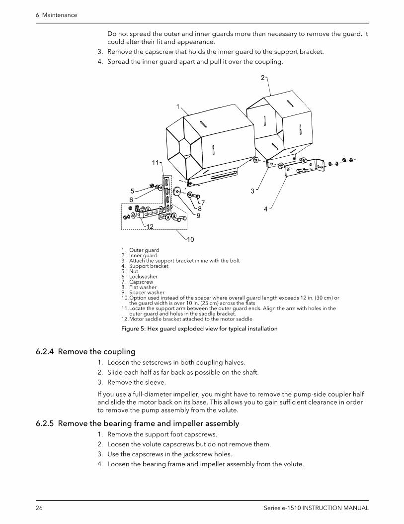
Do not spread the outer and inner guards more than necessary to remove the guard. Itcould alter their fit and appearance.
3. Remove the capscrew that holds the inner guard to the support bracket.
4. Spread the inner guard apart and pull it over the coupling.
1
2
3
4
56
12
10
987
11
1. Outer guard2. Inner guard3. Attach the support bracket inline with the bolt4. Support bracket5. Nut6. Lockwasher7. Capscrew8. Flat washer9. Spacer washer10.Option used instead of the spacer where overall guard length exceeds 12 in. (30 cm) or
the guard width is over 10 in. (25 cm) across the flats11.Locate the support arm between the outer guard ends. Align the arm with holes in the
outer guard and holes in the saddle bracket.12.Motor saddle bracket attached to the motor saddle
Figure 5: Hex guard exploded view for typical installation
6.2.4 Remove the coupling1. Loosen the setscrews in both coupling halves.
2. Slide each half as far back as possible on the shaft.
3. Remove the sleeve.
If you use a full-diameter impeller, you might have to remove the pump-side coupler halfand slide the motor back on its base. This allows you to gain sufficient clearance in orderto remove the pump assembly from the volute.
6.2.5 Remove the bearing frame and impeller assembly1. Remove the support foot capscrews.
2. Loosen the volute capscrews but do not remove them.
3. Use the capscrews in the jackscrew holes.
4. Loosen the bearing frame and impeller assembly from the volute.
6 Maintenance
26 Series e-1510 INSTRUCTION MANUAL
WARNING:
Make certain that the internal pressure of the pump is relieved beforeyou continue. Failure to follow these instructions could result in seriouspersonal injury or death, or property damage.
5. Remove the seal flush piping if it is used.
6. Remove the volute capscrews.
7. Remove the bearing frame and impeller assembly from the volute.
6.2.6 Remove the impeller
The following warning applies to all models except e-1510-es:
WARNING:
Never apply heat to remove an impeller. The use of heat may cause an explosion due totrapped liquid, resulting in severe physical injury and property damage.
CAUTION:
Wear heavy work gloves when you handle impellers. The sharp edges can cause physicalinjury.
1. For all models except the e-1510-es, remove the impeller capscrew.
2. Remove these parts:
– For all models except the e-1510-es, remove the lock washer and the washer.– For the e-1510-es, remove the impeller nut, turning counter-clockwise.
3. Remove the impeller.
– For all models except e-1510-es, slide impeller off shaft.– For e-1510-es, remove by turning counter-clockwise. Hold the shaft at the coupling
end and use a strap wrench on the impeller. If the impeller nut or threaded impellercannot be removed by turning, heat only as necessary with a torch and disassemblewhile hot. Wear heat resistant gloves.
4. Remove the impeller key for all models except e-1510-es.
6.2.7 Remove the mechanical seal (e-1510 and e-1510-F)1. Remove the rotating portion of the seal.
If necessary, use a screwdriver to loosen the rubber ring.
2. Remove the seal insert, the insert gasket, and the retainer if it is used.
6.2.8 Remove the seal or packing rings (e-1510-S and e-1510-PF)1. Remove the hex nuts from the seal cap bolts.
2. Remove the coverplate screws.
3. Remove the coverplate from the bracket.
4. Remove the seal assembly or packing rings.
6.3 Pre-assembly inspectionsGuidelines
Before you assemble the pump parts, make sure you follow these guidelines:
• Inspect the pump parts according to the information in these pre-assembly topicsbefore you reassemble your pump. Replace any part that does not meet the requiredcriteria.
• Make sure that the parts are clean. Clean the pump parts in solvent in order to removeoil, grease, and dirt.
6 Maintenance
Series e-1510 INSTRUCTION MANUAL 27

NOTICE:
Protect machined surfaces while you clean the parts. Failure to do so may result inequipment damage.
6.3.1 Replacement guidelines
Impeller replacement
This table shows the criteria for replacing the impeller:
Impeller parts When to replace
Impeller vanes • When grooved deeper than 1/16 in. (1.6 mm), or• When worn evenly more than 1/32 in. (0.8 mm)
Vane edges When you see cracks, pitting, or corrosion damage
Gaskets, O-rings, and seats replacement
• Replace all gaskets and O-rings at each overhaul and disassembly.• Inspect the seats. They must be smooth and free of physical defects.• Replace parts if the seats are defective.
6.3.2 Shaft and sleeve inspection
Inspection criteria
Inspect the shaft and sleeve according to this criteria:
• Thoroughly clean the shaft and sleeve.• Thoroughly clean the coverplate seal cavity.• Inspect the surface for damage such as pitting, corrosion, nicks, and scratches.
Replace these parts if they are damaged.
6.3.3 Bearing frame inspectionCheck the bearing frame for these conditions:
• Visually inspect the bearing frame and support foot for cracks.• Inspect the bearing frame for smooth and free operation.• Inspect the bearing frame for contamination by pumped fluids.
Repair or replace the bearing frame as necessary.
6.3.4 Impeller trimming guidelines
Machining
When it is necessary to reduce the pump flow rate and generated head by trimming theimpeller diameter, the following guidelines apply for stainless steel impellers:
• Review the pump hydraulic selection data and consult your local Xylem representativeto select the proper reduced diameter.
• For the e-1510-4AD model, before trimming the impeller refer to the e-1510-4ADangle cut guidelines.
• The recommended machining insert is Sandvick CNMG 432-1125 or equal withoutcoolant at 250 surface feet per minute (SFM) (76.2 surface meter per minute (SMM)).
• To calculate the spindle speed (RPM), use the formula RPM=(SFM*12)/(3.1416*diameter of cut, in.) (RPM=(SMM*39.37)/(3.1416* diameter of cut, mm/25.4)). Thisresults in the following:
Impeller Maximum Diameter Recommended Maximum Spindle Speed (RPM)
7 in. (177.8 mm) 136
9.5 in. (241.3 mm) 100
11 in. (279.4 mm) 87
13.5 in. (342.9 mm) 71
6 Maintenance
28 Series e-1510 INSTRUCTION MANUAL

• Recommended rough cut feed rate per revolution is 0.008 in. (0.20 mm) and depth ofcut is 0.050 in (1.27 mm).
• Recommended finish cut feed rate per revolution is 0.015 in. (0.38 mm) and depth ofcut is 0.010 in (0.25 mm).
Balancing
It is recommended that impellers trimmed more than 5% in diameter be rebalanced perISO 1940 grade G6.3.
Angle cut guidelines
Model e-1510-4AD pump impellers must be angle cut at reduced diameters according tothe following information.
ØA ØB
C
Figure 6: 4AD impeller trim — 0.125 in. (3.17 mm) increments
A B C
Hydraulic diameter, nominal, asshown on selection curves
Diameter at impeller inlet sideshroud
Trim angle
From maximum diameter 7 in.(177.8 mm) to 6.125 in. (155.6 mm)
Use diameter from selection curves 0 degrees, no angle
6, 5.875, 5.75, 5.625 in. (162.4 to142.9 mm)
B = A plus 0.250 in. (6.35 mm) 8 degrees
5.5, 5.375, 5.25, 5.125, minimum 5in. (139.7 to 127.0 mm)
B = A plus 0.375 in. (9.53 mm) 8 degrees
6.4 Reassembly6.4.1 Seal assembly
6.4.1.1 Assemble the standard mechanical seal (e-1510 and e-1510-F)1. Lubricate the shaft sleeve and coverplate seal cavity with soapy water.
Do not use a petroleum lubricant.
2. Install a new insert gasket.
3. Install a new seal insert and make sure that the indentation is against the insert gasket.
4. Slide a new rotating seal assembly onto the shaft sleeve.
5. Push the top of the compression ring with a screwdriver until the seal is tight againstthe seal insert.
6. Install the seal spring and point the narrow end toward the seal.
6 Maintenance
Series e-1510 INSTRUCTION MANUAL 29

213
4
5
67
8
9
11
1314
16 1718
10
12
15
1. Impeller2. Vent Plug3. Volute4. Volute Gasket5. Coverplate6. Seal Assembly7. Bearing Frame8. Shaft9. Support Foot10.Support Foot Capscrews11.Slinger12.Bearing Frame Capscrews13.Shaft Sleeve14.Impeller Key15.Impeller Washer16.Impeller Lock Washer17.Drain Plug18.Impeller Capscrew or Nut
6.4.1.2 Assemble the single mechanical seal (e-1510-S)1. Lubricate the shaft sleeve and seal cap with soapy water.
Do not use a petroleum lubricant.
2. Insert a stationary seal with an O-ring into the seal cap and slide it onto the shaft.
3. Replace the seal cap gasket.
4. Slide the rotating portion of the seal assembly onto the shaft sleeve and lock it inplace.
ID seal size Distance between collar and impeller end of the shaft sleeve
1-1/4 in. (3.175 cm) 1-13/32 in. (3.571 cm)
1-5/8 in. (4.128 cm) 1-1/4 in. (3.175 cm)
2-3/8 in. (6.033 cm) 1-1/4 in. (3.175 cm)
5. Assemble the coverplate onto the bracket.
6. Tighten the capscrews according to the Capscrew torque table.
7. Attach the seal cap to the coverplate.
8. Tighten the hex nuts on the seal cap bolts according to the Capscrew torque table.
6 Maintenance
30 Series e-1510 INSTRUCTION MANUAL
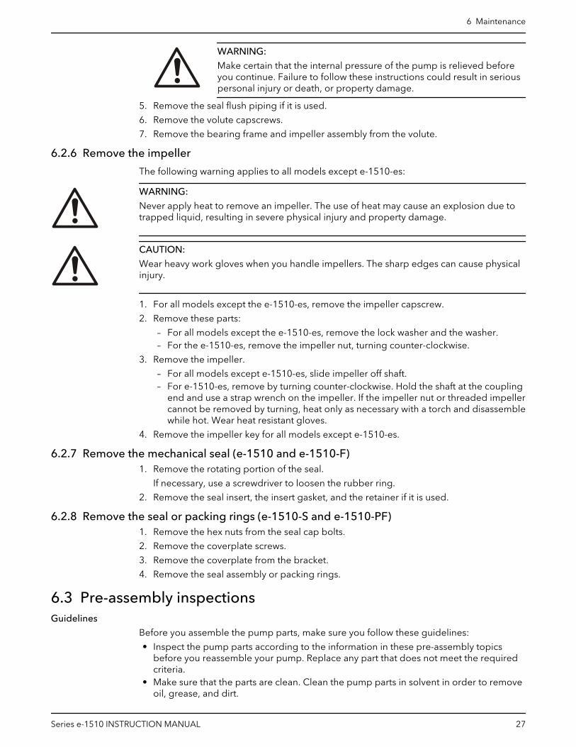
2
3
4
5
6
7
9
1
8
1. O-ring2. Coverplate3. For 1-1/4 in. seal: 1-13/32 in. (3.571 cm)4. For 1-5/8 in. seal and 2-2/3 in. seal; 1-1/4 in. (3.175 cm)5. Seal locking collar6. Seal cap bolt7. Seal cap8. O-ring9. Motor end
6.4.2 Impeller installation
6.4.2.1 Install the impeller (all except the e-1510-es)1. Install the impeller, impeller washer, lock washer, and capscrew.
2. Tighten the capscrew according to the Capscrew torque values table.
6.4.2.2 Install the impeller (e-1510-es)1. Apply Loctite 262 or equivalent to threads on the shaft.
2. Thread impeller on the shaft by turning clockwise until it bottoms on the sleeve.
3. Apply Loctite 262 or equivalent to the threads on the impeller nut.
4. Thread impeller nut on the shaft and tighten to 5 ft-lbs (7 Nm) or hand tight by turningclockwise.
6 Maintenance
Series e-1510 INSTRUCTION MANUAL 31

6.4.3 Assemble the packed stuffing box (e-1510-PF)
1235 4
67
8
11
1213
14
16 20
19
910
15
1718
1. Impeller2. Volute3. Volute Gasket4. Coverplate5. Coverplate Capscrews6. Flushing Tube7. Lantern Ring8. Packing9. Packing Gland10.Bearing Frame11.Shaft12.Slinger13.Shaft Sleeve14.Bracket15.Impeller Key16.Impeller Washer17.Volute Capscrews18.Impeller Lock Washer19.Drain Plug20.Impeller Capscrew
1. Insert two packing rings into the stuffing box.
2. Insert the lantern ring and the last two pieces of packing.
Make sure that the joints on the packing rings are staggered 90º.
3. Install, but do not tighten, the packing gland.
4. Install the coverplate over the pump shaft.
5. Tighten the capscrews according to the Capscrew torque table in the Maintenancechapter.
6. Tighten the packing gland to compress the packing.
See the note on the packed pump operation in the Operations chapter for moreinformation.
6.4.4 Reinstall the bearing frame and impeller assembly1. Install a new volute gasket.
2. Install the bearing frame assembly into the volute.
3. Tighten the volute capscrews according to the Capscrew torque values table.
6 Maintenance
32 Series e-1510 INSTRUCTION MANUAL
4. Install a flush piping if it is used.
5. Install the support foot capscrews and tighten them according to the Capscrew torquevalues table.
6. Install and align the coupling.
7. Install the drain plug and close the drain valve.
6.4.5 Install the hex coupling guard1. Slide the inner guard into the outer guard.
2. Spread the guards and place them over the coupling.
Do not spread the inner and outer guards more than necessary for guard installation,as it can alter their fit and appearance.
3. Straddle the support bracket with the guards and install a capscrew through the holein the support bracket and guard located closest to the pump.
Do not tighten the capscrew.
4. Install the outer guard capscrews according to the directions in this table.
If... Then...
The pump has a motor saddlesupport bracket
Ensure that the outer guard straddles the support arm and install the tworemaining capscrews.Do not tighten the capscrews.
The pump does not have a motorsaddle support bracket
Insert the spacer washer between the holes located closest to the motor inthe outer guard and install the two remaining capscrews.Do not tighten the capscrews.
5. Position the outer guard so that there is less than 1/4 in. (0.64 cm) of exposed shaft.
6. Hold the guard in this position and tighten the three capscrews.
7. Open the isolation valves and inspect the pump for leaks.
8. Return the pump to service if it is not leaking.
6.4.6 Torque values
Capscrew torque
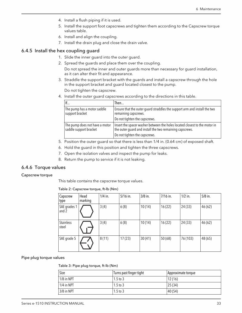
This table contains the capscrew torque values.
Table 2: Capscrew torque, ft-lb (Nm)
Capscrewtype
Headmarking
1/4 in. 5/16 in. 3/8 in. 7/16 in. 1/2 in. 5/8 in.
SAE grades 1and 2
3 (4) 6 (8) 10 (14) 16 (22) 24 (33) 46 (62)
Stainlesssteel
3 (4) 6 (8) 10 (14) 16 (22) 24 (33) 46 (62)
SAE grade 5 8 (11) 17 (23) 30 (41) 50 (68) 76 (103) 48 (65)
Pipe plug torque values
Table 3: Pipe plug torque, ft-lb (Nm)
Size Turns past finger tight Approximate torque
1/8 in NPT 1.5 to 3 12 (16)
1/4 in NPT 1.5 to 3 25 (34)
3/8 in NPT 1.5 to 3 40 (54)
6 Maintenance
Series e-1510 INSTRUCTION MANUAL 33

Size Turns past finger tight Approximate torque
1/2 in NPT 1.5 to 3 54 (73)
6.4.7 Dealer servicing
If trouble occurs that cannot be rectified, contact your local sales and servicerepresentative and be prepared to provide this information:
1. Complete nameplate data of pump and motor
2. Suction and discharge pipe pressure gauge readings
3. Ampere draw of the motor
4. A sketch of the pump hook-up and piping
6 Maintenance
34 Series e-1510 INSTRUCTION MANUAL

7 Product warrantyCommercial warranty
Warranty. For goods sold to commercial buyers, Seller warrants the goods sold to Buyerhereunder (with the exception of membranes, seals, gaskets, elastomer materials,coatings and other "wear parts" or consumables all of which are not warranted except asotherwise provided in the quotation or sales form) will be (i) be built in accordance withthe specifications referred to in the quotation or sales form, if such specifications areexpressly made a part of this Agreement, and (ii) free from defects in material andworkmanship for a period of one (1) year from the date of installation or eighteen (18)months from the date of shipment (which date of shipment shall not be greater thanndythirty (30) days after receipt of notice that the goods are ready to ship), whichever shalloccur first, unless a longer period is specified in the product documentation (the“Warranty”).
Except as otherwise required by law, Seller shall, at its option and at no cost to Buyer,either repair or replace any product which fails to conform with the Warranty providedBuyer gives written notice to Seller of any defects in material or workmanship within ten(10) days of the date when any defects or non-conformance are first manifest. Undereither repair or replacement option, Seller shall not be obligated to remove or pay for theremoval of the defective product or install or pay for the installation of the replaced orrepaired product and Buyer shall be responsible for all other costs, including, but notlimited to, service costs, shipping fees and expenses. Seller shall have sole discretion as tothe method or means of repair or replacement. Buyer’s failure to comply with Seller’srepair or replacement directions shall terminate Seller’s obligations under this Warrantyand render the Warranty void. Any parts repaired or replaced under the Warranty arewarranted only for the balance of the warranty period on the parts that were repaired orreplaced. Seller shall have no warranty obligations to Buyer with respect to any product orparts of a product that have been: (a) repaired by third parties other than Seller or withoutSeller’s written approval; (b) subject to misuse, misapplication, neglect, alteration,accident, or physical damage; (c) used in a manner contrary to Seller’s instructions forinstallation, operation and maintenance; (d) damaged from ordinary wear and tear,corrosion, or chemical attack; (e) damaged due to abnormal conditions, vibration, failureto properly prime, or operation without flow; (f) damaged due to a defective powersupply or improper electrical protection; or (g) damaged resulting from the use ofaccessory equipment not sold or approved by Seller. In any case of products notmanufactured by Seller, there is no warranty from Seller; however, Seller will extend toBuyer any warranty received from Seller’s supplier of such products.
THE FOREGOING WARRANTY IS EXCLUSIVE AND IN LIEU OF ANY AND ALL OTHEREXPRESS OR IMPLIED WARRANTIES, GUARANTEES, CONDITIONS OR TERMS OFWHATEVER NATURE RELATING TO THE GOODS PROVIDED HEREUNDER, INCLUDINGWITHOUT LIMITATION ANY IMPLIED WARRANTIES OF MERCHANTABILITY ANDFITNESS FOR A PARTICULAR PURPOSE, WHICH ARE HEREBY EXPRESSLY DISCLAIMEDAND EXCLUDED. EXCEPT AS OTHERWISE REQUIRED BY LAW, BUYER’S EXCLUSIVEREMEDY AND SELLER’S AGGREGATE LIABILITY FOR BREACH OF ANY OF THEFOREGOING WARRANTIES ARE LIMITED TO REPAIRING OR REPLACING THE PRODUCTAND SHALL IN ALL CASES BE LIMITED TO THE AMOUNT PAID BY THE BUYER FOR THEDEFECTIVE PRODUCT. IN NO EVENT SHALL SELLER BE LIABLE FOR ANY OTHER FORMOF DAMAGES, WHETHER DIRECT, INDIRECT, LIQUIDATED, INCIDENTAL,CONSEQUENTIAL, PUNITIVE, EXEMPLARY OR SPECIAL DAMAGES, INCLUDING BUTNOT LIMITED TO LOSS OF PROFIT, LOSS OF ANTICIPATED SAVINGS OR REVENUE,LOSS OF INCOME, LOSS OF BUSINESS, LOSS OF PRODUCTION, LOSS OFOPPORTUNITY OR LOSS OF REPUTATION.
7 Product warranty
Series e-1510 INSTRUCTION MANUAL 35

Limited consumer warranty
Warranty. For goods sold for personal, family or household purposes, Seller warrants thegoods purchased hereunder (with the exception of membranes, seals, gaskets, elastomermaterials, coatings and other "wear parts" or consumables all of which are not warrantedexcept as otherwise provided in the quotation or sales form) will be free from defects inmaterial and workmanship for a period of one (1) year from the date of installation oreighteen (18) months from the product date code, whichever shall occur first, unless alonger period is provided by law or is specified in the product documentation (the“Warranty”).
Except as otherwise required by law, Seller shall, at its option and at no cost to Buyer,either repair or replace any product which fails to conform with the Warranty providedBuyer gives written notice to Seller of any defects in material or workmanship within ten(10) days of the date when any defects or non-conformance are first manifest. Undereither repair or replacement option, Seller shall not be obligated to remove or pay for theremoval of the defective product or install or pay for the installation of the replaced orrepaired product and Buyer shall be responsible for all other costs, including, but notlimited to, service costs, shipping fees and expenses. Seller shall have sole discretion as tothe method or means of repair or replacement. Buyer’s failure to comply with Seller’srepair or replacement directions shall terminate Seller’s obligations under this Warrantyand render this Warranty void. Any parts repaired or replaced under the Warranty arewarranted only for the balance of the warranty period on the parts that were repaired orreplaced. The Warranty is conditioned on Buyer giving written notice to Seller of anydefects in material or workmanship of warranted goods within ten (10) days of the datewhen any defects are first manifest.
Seller shall have no warranty obligations to Buyer with respect to any product or parts of aproduct that have been: (a) repaired by third parties other than Seller or without Seller’swritten approval; (b) subject to misuse, misapplication, neglect, alteration, accident, orphysical damage; (c) used in a manner contrary to Seller’s instructions for installation,operation and maintenance; (d) damaged from ordinary wear and tear, corrosion, orchemical attack; (e) damaged due to abnormal conditions, vibration, failure to properlyprime, or operation without flow; (f) damaged due to a defective power supply orimproper electrical protection; or (g) damaged resulting from the use of accessoryequipment not sold or approved by Seller. In any case of products not manufactured bySeller, there is no warranty from Seller; however, Seller will extend to Buyer any warrantyreceived from Seller’s supplier of such products.
THE FOREGOING WARRANTY IS PROVIDED IN PLACE OF ALL OTHER EXPRESSWARRANTIES. ALL IMPLIED WARRANTIES, INCLUDING BUT NOT LIMITED TO THEIMPLIED WARRANTIES OF MERCHANTABILITY AND FITNESS FOR A PARTICULARPURPOSE, ARE LIMITED TO ONE (1) YEAR FROM THE DATE OF INSTALLATION OREIGHTEEN (18) MONTHS FROM THE PRODUCT DATE CODE , WHICHEVER SHALLOCCUR FIRST. EXCEPT AS OTHERWISE REQUIRED BY LAW, BUYER’S EXCLUSIVEREMEDY AND SELLER’S AGGREGATE LIABILITY FOR BREACH OF ANY OF THEFOREGOING WARRANTIES ARE LIMITED TO REPAIRING OR REPLACING THE PRODUCTAND SHALL IN ALL CASES BE LIMITED TO THE AMOUNT PAID BY THE BUYER FOR THEDEFECTIVE PRODUCT. IN NO EVENT SHALL SELLER BE LIABLE FOR ANY OTHER FORMOF DAMAGES, WHETHER DIRECT, INDIRECT, LIQUIDATED, INCIDENTAL,CONSEQUENTIAL, PUNITIVE, EXEMPLARY OR SPECIAL DAMAGES, INCLUDING BUTNOT LIMITED TO LOSS OF PROFIT, LOSS OF ANTICIPATED SAVINGS OR REVENUE,LOSS OF INCOME, LOSS OF BUSINESS, LOSS OF PRODUCTION, LOSS OFOPPORTUNITY OR LOSS OF REPUTATION.
Some states do not allow limitations on how long an implied warranty lasts, so the abovelimitation may not apply to you. Some states do not allow the exclusion or limitation ofincidental or consequential damages, so the above exclusions may not apply to you. Thiswarranty gives you specific legal rights, and you may also have other rights which mayvary from state to state.
7 Product warranty
36 Series e-1510 INSTRUCTION MANUAL

To make a warranty claim, check first with the dealer from whom you purchased theproduct or visit www.xyleminc.com for the name and location of the nearest dealerproviding warranty service.
7 Product warranty
Series e-1510 INSTRUCTION MANUAL 37

Xylem |’zīləm|
1) The tissue in plants that brings water upward from the roots;2) a leading global water technology company.
We’re a global team unified in a common purpose: creating advancedtechnology solutions to the world’s water challenges. Developing newtechnologies that will improve the way water is used, conserved, and re-used inthe future is central to our work. Our products and services move, treat, analyze,monitor and return water to the environment, in public utility, industrial,residential and commercial building services settings. Xylem also provides aleading portfolio of smart metering, network technologies and advancedanalytics solutions for water, electric and gas utilities. In more than 150 countries,we have strong, long-standing relationships with customers who know us for ourpowerful combination of leading product brands and applications expertise witha strong focus on developing comprehensive, sustainable solutions.
For more information on how Xylem can help you, go to www.xylem.com
Xylem Inc.8200 N. Austin AvenueMorton Grove IL 60053Tel: (847) 966–3700Fax: (847) 965–8379www.xylem.com/bellgossett
Visit our Web site for the latest version of this documentand more information
The original instruction is in English. All non-Englishinstructions are translations of the original instruction.
© 2019 Xylem Inc
Bell & Gossett is a trademark of Xylem Inc or one of itssubsidiaries.
P2001406_E_en-US_2019-02_IOM.e1510


