For parts or assistance, call Flotec Customer Service at 1-800-365-6832
READ AND FOLLOW SAFETY INSTRUCTIONS!
This is the safety alert symbol. When you see thissymbol on your pump or in this manual, look for
one of the following signal words and be alert to thepotential for personal injury:
warns about hazards that will cause seriouspersonal injury, death or major property damage ifignored.
warns about hazards that can cause seriouspersonal injury, death or major property damage ifignored.
warns about hazards that will or can causeminor personal injury or property damage if ignored.
The label NOTICE indicates special instructions whichare important but not related to hazards.
Carefully read and follow all safety instructions in thismanual and on pump.
Keep safety labels in good condition. Replace missing or damaged safety labels.
ELECTRICAL SAFETYCapacitor voltage may be hazardous. To
discharge motor capacitor, hold insulated handle screw-driver BY THE HANDLE and short capacitor terminalstogether. Do not touch metal screwdriver blade orcapacitor terminals. If in doubt, consult a qualified elec-trician.
GENERAL SAFETYDo not touch an operating motor. Modern
motors are designed to operate at high temperatures. Toavoid burns when servicing pump, allow it to cool for 20minutes after shut-down before handling.
Do not allow pump or any system component to freeze.To do so will void warranty.
Pump water only with this pump.
Periodically inspect pump and system components.
Wear safety glasses at all times when working on pumps.
Keep work area clean, uncluttered and properly lighted;store properly all unused tools and equipment.
Keep visitors at a safe distance from the work areas.
Pump body may explode if used as abooster pump unless relief valve capable of passing fullpump flow at 75 psi is installed.
WARNINGHazardous pressure! Install pressure relief valve in discharge pipe.
Release all pressure on system before working on any component.
WARNING
Hazardous voltage.Can shock, burn, orcause death.
Ground pump before connecting to power supply. Disconnect powerbefore working on pump,motor or tank.
Wire motor for correctvoltage. See “Electrical”
section of this manual andmotor nameplate.
Ground motor beforeconnecting to power
supply.
Meet National Electri-cal Code, Canadian
Electrical Code, and localcodes for all wiring.
Follow wiring instruc-tions in this manual
when connecting motor topower lines.
Table of Contents 3
Thank you for purchasing a top quality, factory tested pump.Page
General Safety .....................................................................................................2Warranty ..............................................................................................................3Replacing An Existing Pump ................................................................................4New Shallow Well Installation.........................................................................5, 6
• Well Point (Driven Point)• Cased Well, 2" or larger casing• Installation for Surface Water
New Deep Well Installation.................................................................................7• 4-inch or larger well casing (A “Double Pipe” Well)• 2-inch well casing (A “Single Pipe” Well)
Discharge Pipe and Pressure Tank Connections ...................................................8Electrical ........................................................................................................9, 10Preparing To Start The Pump – Deep Well..........................................................11Preparing To Start The Pump – Shallow Well ....................................................12Troubleshooting..................................................................................................13Repair Parts ..................................................................................................14-16
ATTACH ORIGINAL RECEIPT HERE FOR WARRANTY CONSIDERATION.
FLOTEC warrants to the original consumer purchaser (“Purchaser”) of its products that they are free from defects in material or workmanship.
If within twelve (12) months from the date of the original consumer purchase any such product shall prove to be defective, it shall be repaired orreplaced at FLOTEC’s option, subject to the terms and conditions set forth below.Your original receipt of purchase is required to determine war-ranty eligibility.
Exceptions to the Twelve (12) Month Warranty
Product Warranty PeriodDrill Pump, Pitcher Pump, In-line Water Filter Cartridge 90 days
1/3 HP Submersible Sump Pumps, INTELLIPUMP (Model FP0S1775A)2 YearsBack-up Sump Pump System (Model FP2800DCC)
4" Submersible Well Pumps, 1/2 HP Submersible Sump Pumps3 YearsModels FPSC2200A-10 and FPSC2250A-10
Pre-Charge Water System Tank, Models FPSC3200A-10 and FPSC3250A-10 5 Years
Purchaser must pay all labor and shipping charges necessary to replace product covered by this warranty. This warranty shall not apply toacts of God, nor shall it apply to products which, in the sole judgement of FLOTEC, have been subject to negligence, abuse, accident, mis-application, tampering, alteration; nor due to improper installation, operation, maintenance or storage; nor to other than normal application,use or service, including but not limited to, operational failures caused by corrosion, rust or other foreign materials in the system, or opera-tion at pressures in excess of recommended maximums.
Requests for service under this warranty shall be made by returning the defective product to the Retail outlet or to FLOTEC as soon as pos-sible after the discovery of any alleged defect. FLOTEC will subsequently take corrective action as promptly as reasonably possible. Norequests for service under this warranty will be accepted if received more than 30 days after the term of the warranty.
This warranty sets forth FLOTEC’s sole obligation and purchaser’s exclusive remedy for defective products.
FLOTEC SHALL NOT BE LIABLE FOR ANY CONSEQUENTIAL, INCIDENTAL, OR CONTINGENT DAMAGES WHATSOEVER.
THE FOREGOING WARRANTIES ARE EXCLUSIVE AND IN LIEU OF ALL OTHER EXPRESS WARRANTIES. IMPLIED WARRANTIES,INCLUDING BUT NOT LIMITED TO THE IMPLIED WARRANTIES OF MERCHANTABILITY AND FITNESS FOR A PARTICULAR PUR-POSE, SHALL NOT EXTEND BEYOND THE DURATION OF THE APPLICABLE EXPRESS WARRANTIES PROVIDED HEREIN.
Some states do not allow the exclusion or limitation of incidental or consequential damages or limitations on how long an implied warrantylasts, so the above limitations or exclusions may not apply to you. This warranty gives you specific legal rights and you may also have otherrights which vary from state to state.
DEEP WELLHazardous voltage. Disconnect power to pump before working
on pump or motor.
Step 1. Drain and remove the old pump. Check pipe for scale, lime, rust,etc., and replace it if necessary.
Step 2. Install the control valve and pressure gauge in the pump body (seeFigure 1).
Step 3. If your old pump has the suction pipe (the larger port – see Figure 2)below the drive port, you will need to install flexible pipe betweenthe well head and the pump so that the connection will be correct.(See Figure 3).
NOTICE: Your old ejector (in the well) may not be properlymatched to your new pump. If the pump does not perform properly,we recommend that you install Flotec ejector kit FP4800.
Step 4. Install the pump in the system. Make sure that all pipe joints in thesuction pipe are air-tight as well as water tight. If the suction pipecan suck air, the pump will not be able to pull water from the well.
Step 5. Adjust the pump mounting height so that the plumbing connectionsdo not put a strain on the pump body. Support the pipe so that thepump body does not take the weight of piping or fittings.
You have just completed the well plumbing for your new deep well jetpump. Please go to Page 8 for discharge pipe and tank connections.
SHALLOW WELLHazardous voltage. Disconnect power to pump before working
on pump or motor.
Step 1. Drain and remove the old pump. Check the old pipe for scale, lime,rust, etc., and replace it if necessary.
Step 2. Install the control valve and pressure gauge in the pump body (seeFigure 1).
Step 3. Install ejector kit FP4855 with a Series 4200, or kit FP4875 with aSeries 4300 pump (kits are sold separately). Follow the instructionsprovided with the kit. Be sure to align the venturi with the top holeon the front of the pump (see Figure 4).
NOTICE: Always replace the ejector when replacing the pump in ashallow well installation.
Step 4. Install the pump in the system. Make sure that all pipe joints in thesuction pipe are air-tight as well as water tight. If the suction pipecan suck air, the pump will not be able to pull water from the well.
Step 5. Adjust the pump mounting height so that the plumbing connectionsdo not put a strain on the pump body. Support the pipe so that thepump body does not take the weight of piping or fittings.
You have just completed the well plumbing for your new shallow well jetpump. Please go to Page 8 for discharge pipe and tank connections.
4182 0502
Drive(Smaller)
Port
SuctionPort
Suction(Larger)
Port
2755 0197
Piping omittedfor clarity Discharge
DrivePort
Drive Pipesends waterdown the wellto drive waterup through theSuction Pipeto Pump Suction
SuctionPipe Drive
Pipe
WellHead
If well head and pump don't match, twist reinforced flexible pipe to connect driveand suction pipes.
2759 0197
Tap clampto seat it
4183 0502
For parts or assistance, call Flotec Customer Service at 1-800-365-6832
Figure1: Install Control Valve and Gauge
Figure 2: Drive and Suction Functions
Figure 3: Reversed Connections to Well
Figure 4: Mount Ejector – Shallow Well
New Shallow Well Installation 5
WELL POINT INSTALLATION (Figure 5)Step 1. Install the control valve and pressure gauge in the pump body (see
Figure 1).
Step 2. Install ejector kit FP4855 with a Series 4200 pump, or kit FP4875with a Series 4300 pump (kits are sold separately). Follow theinstructions provided with the kit. Align the venturi with the tophole on the front of the pump (see Figure 4).
Step 3. Drive the well, using “drive couplings” and a “drive cap”. “Drivefittings” are threaded all the way through and allow the pipe endsto butt against each other so that the driving force of the maul iscarried by the pipe and not by the threads. The ordinary fittingsfound in hardware stores are not threaded all the way through thefitting and can collapse under impact. “Drive fittings” are alsosmoother than standard plumbing fittings, making ground penetra-tion easier.
Step 4. Mount the pump as close to the well as possible.
Step 5. Use the fewest possible fittings (especially elbows) when connect-ing the pipe from the well point to the pump suction port. The suc-tion pipe should be at least as large as the suction port on the pump(include a check valve – see Figure 5). Support the pipe so thatthere are no dips or sags in the pipe, so it doesn’t strain the pumpbody, and so that it slopes slightly upward from the well to thepump (high spots can cause air pockets which can air lock thepump). Seal the suction pipe joints with teflon tape or pipe jointcompound approved for use on PVC. Joints must be air- and water-tight. If the suction pipe can suck air, the pump cannot pull waterfrom the well. If one well point does not supply enough water, con-sider connecting two or three well points to one suction pipe.
You have just completed the suction piping for your new shallow well jetpump. Please go to Page 8 for discharge pipe and tank connections
CASED WELL INSTALLATION, 2" OR LARGERCASING (Figure 6)Step 1. Install the control valve and pressure gauge in the pump body (see
Figure 1).
Step 2. Install ejector kit FP4855 with a Series 4200 pump, or kit FP4875with a Series 4300 pump (kits are sold separately). Follow theinstructions provided with the kit. Align the venturi with the tophole on the front of the pump (see Figure 4).
Step 3. Mount the pump as close to the well as possible.
Step 4. Assemble the foot valve, strainer, and well pipe (see Figure 6).Make sure that the foot valve works freely.
Step 5. Lower the pipe into the well until the strainer is five feet above thebottom of the well. It should also be at least 10 feet below thewell’s water level while the pump is running in order to prevent thepump from sucking air. Install a sanitary well seal.
Step 6. Install a priming tee, priming plug, and suction pipe to the pump(see Figure 6). Connect the pipe from the well to the pump suctionport, using the fewest possible fittings – especially elbows – as fit-tings increase friction in the pipe. The suction pipe should be atleast as large as the suction port on the pump. Use teflon tape or a
P
222 0395
To HouseholdWater System
Suction PipeFrom Well
PrimingTee andPlug
Pressure Gaugeand Priming Port
DriveCoupling
DrivePoint
CheckValve
Built-inCheckValve
Notto
Scale
Relief Valve
For parts or assistance, call Flotec Customer Service at 1-800-365-6832
Figure 5: Driven Point Installation
Figure 6: Cased Well Installation
P
256 0395
To HouseholdWater System
Suction PipeFrom Well
Pressure Gaugeand Priming Port
PrimingTee andPlug
Built-in Check Valve
Notto
Scale
WellCasing
FootValve
SanitaryWell Seal
Strainer5-10'
At least10'
Relief Valve
New Shallow Well Installation 6
teflon-based pipe joint compound on threaded pipe joints. Supportthe pipe so that there are no dips or sags in the pipe, so it doesn’tstrain the pump body, and so that it slopes slightly upward from thewell to the pump (high spots can cause air pockets which can airlock the pump). Seal the suction pipe joints with teflon tape or ateflon based pipe joint compound. Joints must be air- and water-tight. If the suction pipe can suck air, the pump cannot pull waterfrom the well.
You have just completed the suction piping for your new shallow well jetpump. Please go to Page 8 for discharge pipe and tank connections.
INSTALLATION FOR SURFACE WATERStep 1. Install the control valve and pressure gauge in the pump body (see
Figure 7).
Step 2. Install ejector kit FP4855 with a Series 4200 pump, or kit FP4875with a Series 4300 pump (kits are sold separately). Follow theinstructions provided with the kit. Align the venturi with the tophole on the front of the pump (see Figure 8).
Step 3. The pump should be installed as close to the water as possible,with the fewest possible fittings (especially elbows) in the suctionpipe. The suction pipe should be at least as large as the suction porton the pump.
Step 4. Assemble a foot valve and suction pipe (see Figure 9). Make surethat the foot valve works freely. Use teflon tape or a teflon-basedpipe joint compound on threaded pipe joints. Protect the foot valveassembly from fish, trash, etc, by installing a screen around it (seeFigure 9).
Step 5. Lower the pipe into the water until the strainer is five feet above thebottom. It should also be at least 10 feet below the water level inorder to prevent the pump from sucking air.
Step 6. Install a priming tee, priming plug, and suction pipe to the pump(see Figure 9). Support the pipe so that there are no dips or sags inthe pipe, so it doesn’t strain the pump body, and so that it slopesslightly upward from the well to the pump (high spots can cause airpockets which can air lock the pump). Seal the suction pipe jointswith teflon tape or a teflon based pipe joint compound. Joints mustbe air- and water-tight. If the suction pipe can suck air, the pumpcannot pull water from the well.
You have just completed the plumbing for your new shallow well jetpump. Please go to Page 8 for discharge pipe and tank connections.
4182 0502
For parts or assistance, call Flotec Customer Service at 1-800-365-6832
Tap clampto seat it
4183 0502
P
257 0395
To HouseholdWater System
Suction PipeFrom Well
FootValve
Screen
Pressure Gaugeand Priming Port
Built-inCheckValve
Notto
Scale
At least10'
5 to 10'
Relief Valve
Figure 7: Install Control Valve andPressure Gauge
Figure 8: Install Ejector
Figure 9: Surface Water Installation
New Deep Well Installation 7
4" OR LARGER WELL (Figure 10)Step 1. Install the control valve and pressure gauge in the pump body. See
Figure 7.
Step 2. Assemble ejector kit FP4800 (sold separately). See Figure 10.Follow the instructions included with the kit in order to match thenozzle and venturi to your well conditions.
Step 3. Mount the pump as close to the well as possible.
Step 4. Connect two pipes (1" drive, 1-1/4" suction) to the ejector andlower the ejector into the well until it is five feet from the bottom. Itshould also be at least 10 feet below the well’s water level whilethe pump is running in order to prevent the pump from sucking air.
Step 5. Install a sanitary well seal and connect the ejector piping to thepump. Use steel nipples through the well seal with flexible polypipe to avoid crushing the plastic pipe when tightening the seal.
Step 6. Support the pipe so that there are no dips or sags in the pipe, so itdoesn’t strain the pump body, and so that it slopes slightly upwardfrom the well to the pump (high spots can cause air pockets whichcan air lock the pump). Seal the suction pipe joints with teflon tapeor a teflon based pipe joint compound. Joints must be air- andwater-tight. If the suction pipe can suck air, the pump cannot pullwater from the well.
You have just completed the plumbing for your new double pipe deepwell jet pump. Please go to Page 8 for discharge pipe and tank connec-tions.
2" WELL (Figure 11)Step 1. Install the control valve and pressure gauge in the pump body. See
Figure 7.
Step 2. Mount the pump as close to the well as possible.
Step 3. Assemble ejector kit FP4840 (sold separately), well piping, and wellhead adapter according to the instructions provided with the ejectorpackage. See Figure 11. Use galvanized drop pipe with turned cou-plings to allow proper flow. Follow the instructions included withthe kit in order to match the nozzle and venturi to your well condi-tions.
Step 4. Run two pipes (one smaller drive pipe, one larger suction pipe)from the well to the pump. Support the pipe so that there are nodips or sags in the pipe, so it doesn’t strain the pump body, and sothat it slopes slightly upward from the well to the pump (high spotscan cause air pockets which can air lock the pump). Seal the suc-tion pipe joints with teflon tape or a teflon based pipe joint com-pound. Joints must be air- and water-tight. If the suction pipe cansuck air, the pump cannot pull water from the well.
You have just completed the plumbing for your new single pipe deep welljet pump. Please go to Page 8 for discharge pipe and tank connections.
P
Suction (Larger)Pipe from Well
To HouseholdWater System
Pressure Gauge and PrimingPlug
WellHead
Drive (Smaller)Line to Well
Venturi
Nozzle
Ejector
Notto
Scale Foot ValveStrainer
266 0395
Relief Valve
For parts or assistance, call Flotec Customer Service at 1-800-365-6832
Figure 10: 4” and Larger Deep Well
Figure 11: 2” (Single Pipe) Deep Well
41
JET
NO
.J3
2P-
24
P
Suction (Larger)Pipe from Well
To HouseholdWater System
ressure Gaugend Priminglug
WellHead
Drive (Smaller)Pipe to Well
Well Casingserves asDrive Pipe
Suction Pipe
Venturi
Nozzle
Ejector
Notto
Scale
267 0295
Relief Valve
Discharge Pipe and Pressure Tank Connections 8
PRE-CHARGE TANK CONNECTION (Figure 12)Step 1. Install a close nipple and a tee in the pump discharge port (see
Figure 12). The pipe size must be at least as large as the dischargeport. Run a pipe or reinforced hose from one arm of the tee to theport on the pre-charged tank.
Step 2. Install a second close nipple and tee with a relief valve in the tee.
Step 3. Connect the other end of the second discharge tee to your plumb-ing system.
Step 4. Check the pre-charge of air in the tank with an ordinary tire gauge.The pre-charge should be 2 PSI less than the cut-in setting of thepump’s pressure switch. The pre-charge is measured when there isno water pressure in the tank. Your new pump has a 30/50 PSIswitch, so adjust the tank pre-charge pressure to 28 PSI.
You have just completed the tank connection for your jet pump. Please goto Pages 9 and 10 for electrical hookup.
STANDARD TANK CONNECTION (Figure 13)Step 1. Install a close nipple and a tee in the pump discharge port. Mount a
relief valve in one arm of the tee.
Step 2. Install a second close nipple and tee in the open arm of the firsttee. Put a priming plug in one arm of the second tee.
Step 3. Run a pipe from the open arm of the second tee to the inlet port ofyour tank. The pipe size must be at least as large as the pump discharge port.
Step 4. Remove the 1/8" NPT pipe plug from the pump Air Volume Control(AVC) port (see Figure 13). Run tubing from the pump’s AVC port tothe port on the AVC mounted on the tank. See instructions providedwith tank and AVC for details.
You have just completed the tank connection for your jet pump. Please goto Pages 9 and 10 for electrical hookup.
P
268 0395
To HouseholdWater SystemPressure Gauge
and PrimingPlug
PressureSwitch
FromWell
ReliefValve
For parts or assistance, call Flotec Customer Service at 1-800-365-6832
To HouseholdWater System
PressureSwitch
FromWell
Air VolumeControl
Air VolumeControl Tube
P
Priming Teeand Plug
276 0395
Relief Valve
Figure 12: Pre-charged TankConnections
Figure 13: Standard Tank Connections
Sealing Pipe JointsUse only Teflon tape or Teflon based joint compounds for mak-ing all threaded connections to the pump itself. Do not usepipe joint compounds on plastic pumps: they can react withthe plastic in pump components. Make sure that all pipe jointsin the suction pipe are air tight as well as water tight. If the suc-tion pipe can suck air, the pump will not be able to pull waterfrom the well.
Electrical 9
Plug Type Voltage Selector
Voltage is factory set to 230 volts. To change to 115 volts:1. Make sure power is off.2. Pull the voltage change plug off of the tabs.3. Move the voltage change plug to the 115 volt posi-
tion. The plug will now cover 2 metal tabs and thearrow on the plug will line up with the 115V arrow onthe label (see Figure 13).
4. Attach the incoming power leads to the two outerscrews on the pressure switch as shown in Figure 12.
5. Attach the ground wire to one of the grounding connections, shown in Figure 12.
6. If there are other wires, they should be capped.7. Reinstall the Motor end cover.
Dial Type Voltage Selector
Voltage is factory set to 230 volts. To change to 115 volts:1. Make sure power is off.2. Turn the dial counter-clockwise until 115 shows in the
dial window as shown in Figure 15.
3. Attach the incoming power leads to the two outerscrews on the pressure switch as shown in Figure 14.
4. Attach the ground wire to the grounding connectionsas shown in Figure 14.
5. If there are other wires, they should be capped.6. Reinstall the Motor end cover.
For parts or assistance, call Flotec Customer Service at 1-800-365-6832
Disconnect power before working on pump, motor, pressure switch, or wiring.
Figure 12:Voltage set to 230 volts, Plug Type
Ground Wire Connection
Voltage Change Plug
Pressure Switch
Power Connections
Figure 13:Voltage set to 115 volts, Plug Type
Figure 14:Voltage set to 230 volts, Dial Type
Ground Wire Connection
Power Supply Connections
VoltageChange Dial
Pressure Switch
Figure 15:Voltage set to 115 volts, Dial Type
NOTE: 1/2 HP motors are wired for 115 volts only, and have no motor wiring to change.3/4 HP or 1 HP motor terminal boards (located under the motor end cover) should look like one of those below. If the motor can operate at either 115 or 230 volts, it is set at the factory to 230 volts. Do not change motor wiringif line voltage is 230 volts, or if you have a single voltage motor.
Never wire a 115 volt motor to a 230 volt line.
MOTOR SWITCH SETTINGS
Electrical 10
Hazardous voltage. Can shock, burn, or kill. Connect groundwire before connecting power supply wires. Use the wire size (includingthe ground wire) specified in the wiring chart. If possible, connect thepump to a separate branch circuit with no other appliances on it.
Explosion hazard. Do not ground to a gas supply line.
WIRING CONNECTIONSFire hazard. Incorrect voltage can cause a fire or seriously
damage the motor and voids the warranty. The supply voltage must bewithin ±10% of the motor nameplate voltage.
NOTICE: Dual-voltage motors are factory wired for 230 volts. If necessary,reconnect the motor for 115 volts, as shown. Do not alter the wiring in sin-gle voltage motors.
Install, ground, wire, and maintain your pump in compliance with theNational Electrical Code (NEC) or the Canadian Electrical Code (CEC), asapplicable, and with all local codes and ordinances that apply. Consultyour local building inspector for code information.
Connection Procedure:Step 1. Connect the ground wire first as shown in Figure 14. The ground
wire must be a solid copper wire at least as large as the power sup-ply wires.
Step 2. There must be a solid metal connection between the pressureswitch and the motor for motor grounding protection. If the pres-sure switch is not connected to the motor, connect the greenground screw in the switch to the green ground screw under themotor end cover. Use a solid copper wire at least as large as thepower supply wires.
Step 3. Connect the ground wire to a grounded lead in a service panel, to ametal underground water pipe, to a metal well casing at least tenfeet (3M) long, or to a ground electrode provided by the powercompany or the hydro authority.
Step 4. Connect the power supply wires to the pressure switch as shown inFigure 14.
You have just completed the wiring for your pump.
Please go to Page 11 or 12 for startup preparations.
For parts or assistance, call Flotec Customer Service at 1-800-365-6832
Max. Load Branch FuseDISTANCE IN FEET FROM MOTOR TO SUPPLY
Never run pump dry. Running pump without water may causepump to overheat, damaging seal and possibly causing burns to personshandling pump. Fill pump with water before starting.
Never run pump against closed discharge. To do so can boilwater inside pump, causing hazardous pressure in unit, risk of explosionand possibly scalding persons handling pump.
Step 1. Open the control valve as far as possible (see Figure 15). Thenremove the priming plug from the pump and fill the pump, fill allpiping between the pump and the well, and make sure that all piping in the well is full. If you have also installed a priming tee inthe suction piping, remove the plug from the tee and fill the suctionpiping.
Step 2. Replace all fill plugs and close the control valve completely (Figure 16).
Step 3. Power on! Start the pump and watch the pressure gauge. The pressure should build rapidly to 50 PSI as the pump primes.
Step 4. After 2 or 3 minutes, the gauge should show pressure. If not, stopthe pump, remove the fill plugs, reopen the control valve, and refillthe pump and piping. You may have to repeat this two or threetimes in order to get all the trapped air out of the piping. Don’t for-get to close the control valve each time before you start the pump.
Step 5. When pressure has built up and stabilized at about 50 PSI, slowlyopen the control valve (see Figure 17) and let the pressure dropuntil the pressure gauge needle starts to flutter. When the needleflutters, close the valve just enough to stop the flutter (see Figure17). Your pump is now operating at its most efficient point.
Step 6. After the pump has built up pressure in the system and shut off,check the pressure switch operation by opening a faucet or two andrunning enough water out to bleed off pressure until the pumpstarts. The pump should start when pressure drops to 30 PSI andstop when pressure reaches 50 PSI. Run the pump through one ortwo complete cycles to verify correct operation. This will also helpclean the system of dirt and scale dislodged during installation.
Congratulations on a successful installation. If you were unsuccessful, please refer to the Troubleshooting section (Page 13) or call our customer service technical staff.
Thank you for purchasing Flotec Products.
POpen control valve as far as possibleand fill pump andpiping through priming port or priming tee.
280 0395
For parts or assistance, call Flotec Customer Service at 1-800-365-6832
Figure 16: Prime Pump
Figure 17: Set Control Valve
PP
C-Close Control Valve until PressureStabilizes 281 0395
Never run pump dry. Running pump without water may causepump to overheat, damaging seal and possibly causing burns to personshandling pump. Fill pump with water before starting.
Never run pump against closed discharge. To do so can boilwater inside pump, causing hazardous pressure in unit, risk of explosionand possibly scalding persons handling pump.
Step 1. Open the control valve as far as possible (see Figure 18). Thenremove the priming plug from the pump and fill the pump, fill allpiping between the pump and the well, and make sure that all pip-ing in the well is full. If you have also installed a priming tee in thesuction piping, remove the plug from the tee and fill the suctionpiping.
Step 2. Replace all fill plugs. Leave the control valve open (in a shallowwell installation, the control valve always stays open).
Step 3. Power on! Start the pump. The pump should pump water in two orthree minutes.
Step 4. If you don’t have water after 2 or 3 minutes, stop the pump andremove the fill plugs. Refill the pump and piping. You may have torepeat this two or three times in order to get all the trapped air outof the piping. The control valve remains open throughout this pro-cedure.
Step 5. After the pump has built up pressure in the system and shut off,check the pressure switch operation by opening a faucet or two andrunning enough water out to bleed off pressure until the pumpstarts. The pump should start when pressure drops to 30 PSI andstop when pressure reaches 50 PSI. Run the pump through one ortwo complete cycles to verify correct operation. This will also helpclean the system of dirt and scale dislodged during installation.
Congratulations on a successful installation. If you were unsuccessful, please refer to the Troubleshooting section (Page 13) or call our customer service technical staff.
Thank you for purchasing Flotec Products.
POpen control valve as far as possibleand fill pump andpiping through priming port or priming tee.
284 0395
For parts or assistance, call Flotec Customer Service at 1-800-365-6832
Figure 18: Open Control Valve
Troubleshooting 13
For parts or assistance, call Flotec Customer Service at 1-800-365-6832
* (Note: Stop pump;then check primebefore looking forother causes.Unscrew primingplug and see if wateris in priming hole).
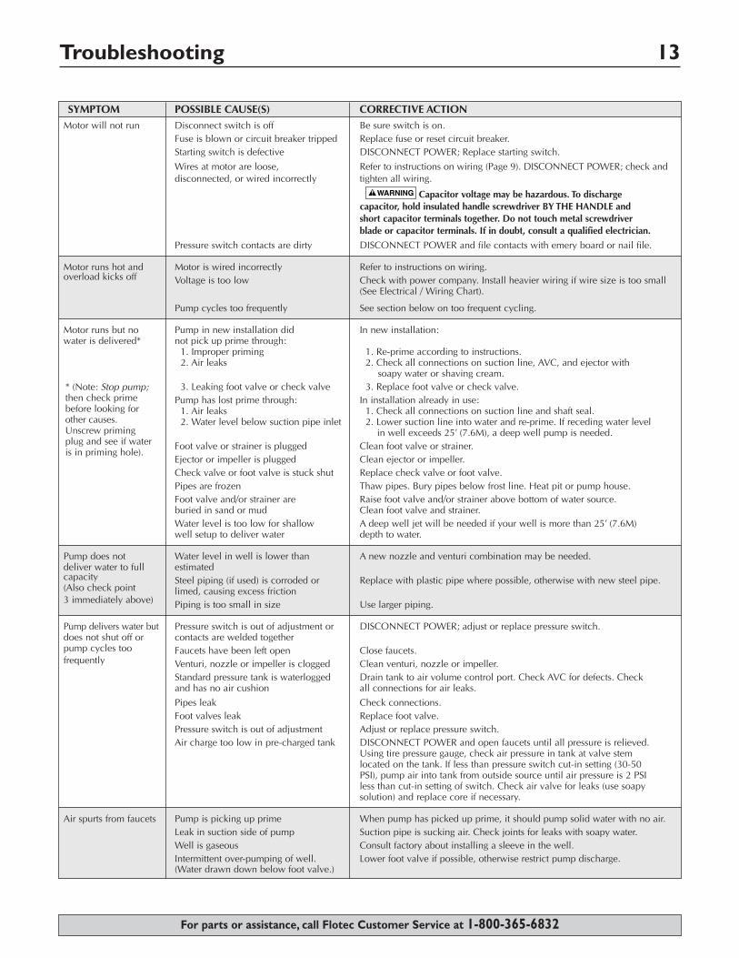
SYMPTOM POSSIBLE CAUSE(S) CORRECTIVE ACTIONMotor will not run Disconnect switch is off Be sure switch is on.
Fuse is blown or circuit breaker tripped Replace fuse or reset circuit breaker.Starting switch is defective DISCONNECT POWER; Replace starting switch.
Wires at motor are loose, Refer to instructions on wiring (Page 9). DISCONNECT POWER; check anddisconnected, or wired incorrectly tighten all wiring.
Capacitor voltage may be hazardous. To discharge capacitor, hold insulated handle screwdriver BY THE HANDLE and short capacitor terminals together. Do not touch metal screwdriver blade or capacitor terminals. If in doubt, consult a qualified electrician.
Pressure switch contacts are dirty DISCONNECT POWER and file contacts with emery board or nail file.
Motor runs hot and Motor is wired incorrectly Refer to instructions on wiring.overload kicks off Voltage is too low Check with power company. Install heavier wiring if wire size is too small
(See Electrical / Wiring Chart).
Pump cycles too frequently See section below on too frequent cycling.
Motor runs but no Pump in new installation did In new installation:water is delivered* not pick up prime through:
1. Improper priming 1. Re-prime according to instructions.2. Air leaks 2. Check all connections on suction line, AVC, and ejector with
soapy water or shaving cream.3. Leaking foot valve or check valve 3. Replace foot valve or check valve.
Pump has lost prime through: In installation already in use:1. Air leaks 1. Check all connections on suction line and shaft seal.2. Water level below suction pipe inlet 2. Lower suction line into water and re-prime. If receding water level
in well exceeds 25’ (7.6M), a deep well pump is needed.Foot valve or strainer is plugged Clean foot valve or strainer.Ejector or impeller is plugged Clean ejector or impeller.Check valve or foot valve is stuck shut Replace check valve or foot valve.Pipes are frozen Thaw pipes. Bury pipes below frost line. Heat pit or pump house.Foot valve and/or strainer are Raise foot valve and/or strainer above bottom of water source.buried in sand or mud Clean foot valve and strainer.Water level is too low for shallow A deep well jet will be needed if your well is more than 25’ (7.6M)well setup to deliver water depth to water.
Pump does not Water level in well is lower than A new nozzle and venturi combination may be needed.deliver water to full estimatedcapacity Steel piping (if used) is corroded or Replace with plastic pipe where possible, otherwise with new steel pipe.(Also check point limed, causing excess friction3 immediately above) Piping is too small in size Use larger piping.
Pump delivers water but Pressure switch is out of adjustment or DISCONNECT POWER; adjust or replace pressure switch.does not shut off or contacts are welded togetherpump cycles too Faucets have been left open Close faucets.frequently Venturi, nozzle or impeller is clogged Clean venturi, nozzle or impeller.
Standard pressure tank is waterlogged Drain tank to air volume control port. Check AVC for defects. Check and has no air cushion all connections for air leaks.
Pipes leak Check connections.Foot valves leak Replace foot valve.Pressure switch is out of adjustment Adjust or replace pressure switch.Air charge too low in pre-charged tank DISCONNECT POWER and open faucets until all pressure is relieved.
Using tire pressure gauge, check air pressure in tank at valve stem located on the tank. If less than pressure switch cut-in setting (30-50 PSI), pump air into tank from outside source until air pressure is 2 PSI less than cut-in setting of switch. Check air valve for leaks (use soapysolution) and replace core if necessary.
Air spurts from faucets Pump is picking up prime When pump has picked up prime, it should pump solid water with no air.Leak in suction side of pump Suction pipe is sucking air. Check joints for leaks with soapy water.Well is gaseous Consult factory about installing a sleeve in the well.Intermittent over-pumping of well. Lower foot valve if possible, otherwise restrict pump discharge.(Water drawn down below foot valve.)
Repair Parts 14
For parts or assistance, call Flotec Customer Service at 1-800-365-6832
76
2
1
39
8
4
5
1 2
34
5
6
78
9
4184 0502
5
Corrosion Resistant ModelsFP4301-01L
FP4312-08FP4322-08FP4332-08
Cast Iron ModelsFP4212-08FP4222-08FP4212J-08FP4222J-08
Model and HPKey Part FP4312-08 FP4322-08 FP4332-08No. Description 1/2HP 3/4HP 1 HP1 Motor AS100CL A100DL A100EL2 Pressure Gauge TC2104 TC2104 TC21043 Pump Body (Back Half) L176-47P L176-47P L176-47P4 Seal & Gasket Kit * FPP1500 FPP1500 FPP15005 V-Clamp Assembly C19-54SS C19-54SS C19-54SS6 Pump Body (Front Half) L76-37P L76-37P L76-37P7 Control Valve Assembly L162-10PS L162-10PS L162-10PS8 Overhaul Kit ** FPP1511 FPP1512 FPP15139 Pressure Switch Assembly TC2151 TC2151 TC2151
Model and HP
FP4212-08 FP4222-08Key Part FP4212J-08# FP4222J-08No. Description 1/2HP 3/4HP
1 Motor - 60 Cycle AS100CL A100DL2 Seal Plate N3-9 N3-93 Seal & Gasket Kit * FPP1550 FPP15504 Pressure Gauge TC2104 TC21045 Control Valve Assembly 01322 013226 Jet Package*** J198-22 J198-227 Pump Body L76-44 L76-448 Overhaul Kit ** FPP1560 FPP15619 Pressure Switch TC2151 TC2151
* Includes: water slinger, seal plate O-ring or gasket, shaft seal, diffuser pad, and diffuser O-ring or gasket.** Includes: Seal and Gasket Kit plus seal plate insert, impeller and diffuser.
*** FP4212J and FP4222J only. For component part numbers, see the following page.# Included in Models FP4212J15H-04 and FP4212J42-04.
Repair instructions are included with all repair kits.
Ejector Package 15
For parts or assistance, call Flotec Customer Service at 1-800-365-6832
N32P 67
41
1
2
3
Surface "B"
6
75
4
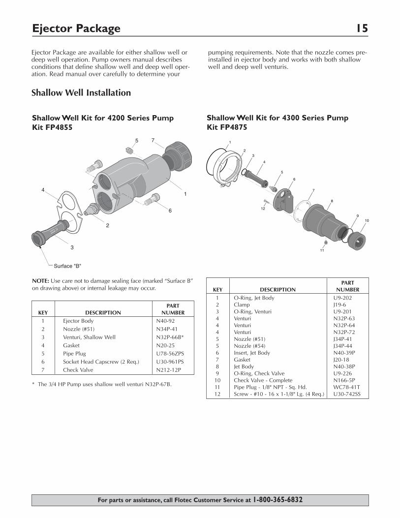
Shallow Well Installation
Ejector Package are available for either shallow well ordeep well operation. Pump owners manual describesconditions that define shallow well and deep well oper-ation. Read manual over carefully to determine your
pumping requirements. Note that the nozzle comes pre-installed in ejector body and works with both shallowwell and deep well venturis.
PARTKEY DESCRIPTION NUMBER
1 Ejector Body N40-922 Nozzle (#51) N34P-41 3 Venturi, Shallow Well N32P-66B*4 Gasket N20-255 Pipe Plug U78-56ZPS6 Socket Head Capscrew (2 Req.) U30-961PS7 Check Valve N212-12P
Shallow Well Kit for 4200 Series Pump Kit FP4855
NOTE: Use care not to damage sealing face (marked “Surface B”on drawing above) or internal leakage may occur.
* The 3/4 HP Pump uses shallow well venturi N32P-67B.