20

SERIES GW WORM REDUCTION PRODUCT FEATURES
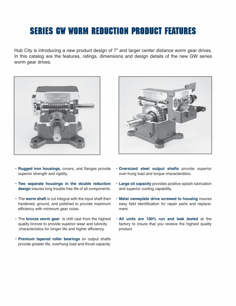
• Rugged iron housings, covers, and flanges providesuperior strength and rigidity.
• Two separate housings in the double reductiondesign insures long trouble free life of all components.
• The worm shaft is cut integral with the input shaft thenhardened, ground, and polished to provide maximumefficiency with minimum gear noise.
• The bronze worm gear is chill cast from the highestquality bronze to provide superior wear and lubricity characteristics for longer life and higher efficiency.
• Premium tapered roller bearings on output shaftsprovide greater life, overhung load and thrust capacity.
• Oversized steel output shafts provide superior over-hung load and torque characteristics.
• Large oil capacity provides positive splash lubricationand superior cooling capability.
• Metal nameplate drive screwed to housing insureseasy field identification for repair parts and replace-ment.
• All units are 100% run and leak tested at the factory to insure that you receive the highest qualityproduct.
Hub City is introducing a new product design of 7” and larger center distance worm gear drives.In this catalog are the features, ratings, dimensions and design details of the new GW seriesworm gear drives.

1EMAIL: [email protected] WEB: www.hubcityinc.com
Worm Gear Features . . . . . . . . . . . . . . . . . . . . . . . . . . . . . . . . . . . . . . . . . . . . . . . . .IFC
Single Reduction Worm Gear Drives . . . . . . . . . . . . . . . . . . . . . . . . . . . . . . . .2 to 5
Ratings . . . . . . . . . . . . . . . . . . . . . . . . . . . . . . . . . . . . . . . . . . . . . . . . . . . . . . . . . .2
Dimensions . . . . . . . . . . . . . . . . . . . . . . . . . . . . . . . . . . . . . . . . . . . . . . . . . . . . .3 to 5
Double Reduction Worm Gear Drives . . . . . . . . . . . . . . . . . . . . . . . . . . . . . . .4 to12
Ratings . . . . . . . . . . . . . . . . . . . . . . . . . . . . . . . . . . . . . . . . . . . . . . . . . . . . . . . . . .4
Dimensions . . . . . . . . . . . . . . . . . . . . . . . . . . . . . . . . . . . . . . . . . . . . . . . . . . . .5 to 12
Accessories . . . . . . . . . . . . . . . . . . . . . . . . . . . . . . . . . . . . . . . . . . . . . . . . . . . . . .13
Engineering Data . . . . . . . . . . . . . . . . . . . . . . . . . . . . . . . . . . . . . . . . . . . . . . . . .14
Warnings & Cautions . . . . . . . . . . . . . . . . . . . . . . . . . . . . . . . . . . . . . . . . . . . . . .15
Terms & Conditions of Sale . . . . . . . . . . . . . . . . . . . . . . . . . . . . . . . . . . . . . . . . .16
GW WORM GEAR DRIVES

R a t i n g Ta b l e
HUB CITY GW WORM GEAR DRIVES
CALL: (605) 225-0360 FAX: (605) 225-05672
1750 341.5 51.170 49.115 9062 6209 66.875 64.312 11866 7761 104.651 100.915 18619 110285 1170 228.3 43.353 41.324 11404 6209 56.618 54.111 14932 7761 88.498 84.908 23431 11028
870 169.8 38.427 36.392 13506 6209 50.159 47.652 17685 7761 78.334 74.774 27750 11028100 19.5 9.250 8.181 26416 6209 13.930 12.417 36447 7761 22.115 19.802 63935 11028
1750 236.5 41.546 39.684 10572 6209 54.370 52.053 13867 7761 84.411 81.109 21413 110287 1/2 1170 158.1 35.247 33.389 13304 6209 46.092 43.796 17451 7761 71.469 68.243 26947 11028
870 117.6 30.763 28.923 15499 6209 40.874 38.569 20668 7761 63.321 60.098 31914 11028100 13.5 6.968 6.089 28388 6209 9.723 8.536 39793 7761 16.549 14.659 67727 11028
1750 179.5 35.744 33.884 11893 6209 43.319 41.160 14447 7761 67.117 64.006 22466 1102810 1170 120.0 30.368 28.509 14967 6209 36.771 34.631 18181 7761 56.888 53.853 28273 11028
870 89.2 26.470 24.631 17391 6209 32.648 30.498 21532 7761 50.458 47.425 33484 11028100 10.3 6.153 5.256 32282 6209 7.960 6.831 41958 7761 13.678 11.837 72712 11028
1750 119.3 25.978 24.294 12827 6209 33.822 31.753 16766 7761 52.789 49.825 26308 1102815 1170 79.8 22.136 20.441 16143 6209 28.791 26.716 21099 7761 44.862 41.921 33107 11028
870 59.3 19.580 17.881 18991 6209 25.297 23.230 24672 7761 39.876 36.918 39209 11028100 6.8 4.157 3.436 31744 6209 5.747 6.820 44195 7761 9.949 8.365 77295 11028
1750 85.4 19.916 18.199 13431 6209 25.929 23.815 17575 7761 40.433 37.394 27597 1102820 1170 57.1 17.045 15.312 16903 6209 22.162 20.037 22118 7761 34.481 31.462 34730 11028
870 42.4 15.130 13.392 19880 6209 19.506 17.390 25815 7761 30.748 27.707 41131 11028100 4.9 3.345 2.595 33520 6209 4.630 3.623 46792 7761 8.011 6.350 82011 11028
1750 71.4 16.911 15.264 13462 6209 21.937 19.930 17578 7761 34.199 31.313 27618 1102825 1170 47.8 14.060 12.444 16417 6209 18.791 16.769 22122 7761 29.224 26.346 34756 11028
870 35.5 12.906 11.234 19931 6209 16.649 14.624 25946 7761 26.104 23.201 41163 11028100 4.1 2.821 2.124 32790 6209 3.862 2.943 45421 7761 6.703 5.175 79871 11028
1750 59.3 14.112 12.576 13356 6209 17.925 16.164 17166 7761 28.529 25.831 27433 1102830 1170 39.7 11.909 10.382 16491 6209 14.993 13.257 21058 7761 24.435 21.734 34523 11028
870 29.5 10.791 9.234 19725 6209 13.674 11.890 25398 7761 21.272 18.617 39769 11028100 3.4 2.295 1.681 31233 6209 2.936 2.211 41088 7761 5.490 4.122 76598 11028
1750 43.8 10.880 9.305 13399 6209 14.079 12.158 17507 7761 21.818 19.077 27471 1102840 1170 29.3 9.178 7.622 16416 6209 12.170 10.229 22032 7761 18.795 16.051 34571 11028
870 21.8 8.450 6.845 19828 6209 10.881 8.933 25875 7761 16.908 14.135 40943 11028100 2.5 1.935 1.278 32194 6209 2.644 1.773 44687 7761 4.539 3.105 78246 11028
1750 35.0 8.740 7.228 13011 6209 11.317 9.460 17028 7761 17.476 14.835 26703 1102850 1170 23.4 7.426 5.930 15966 6209 9.838 7.959 21429 7761 15.128 12.482 33605 11028
870 17.4 6.857 5.317 19250 6209 8.837 6.951 25166 7761 13.204 10.618 38444 11028100 2.0 1.615 0.988 31109 6209 2.224 1.380 43469 7761 3.793 2.411 75935 11028
1750 29.2 7.003 5.657 12220 6209 9.048 7.399 15982 7761 13.983 11.624 25107 1102860 1170 19.5 6.033 4.687 15143 6209 7.629 6.014 19430 7761 12.152 9.780 31597 11028
870 14.5 5.513 4.146 18014 6209 7.126 5.446 23663 7761 10.762 8.416 36566 11028100 1.7 1.273 0.744 28131 6209 1.748 1.038 39244 7761 3.013 1.829 69119 11028
1750 25.0 5.740 4.484 11300 6209 7.370 5.850 14743 7761 11.431 9.220 23235 1102870 1170 16.7 4.963 3.709 13979 6209 6.242 4.755 17921 7761 9.979 7.758 29240 11028
870 12.4 4.567 3.290 16676 6209 5.854 4.306 21829 7761 8.845 6.655 33736 11028100 1.4 1.094 0.595 26222 6209 1.476 0.821 36215 7761 2.589 1.464 64584 11028
Series GW 700 Series GW 800 Series GW 1000Input Output Input Output Output Input Output Output Input Output Output
Ratio RPM RPM HP HP TQ OHL HP HP TQ OHL HP HP TQ OHL
Note: All torque values listed in inch-pounds, all overhung load values listed in pounds. The point of application of the overhung load is considered to beone shaft diameter measured outward from the gear case housing. At speeds above 1750 RPM, units may become thermally limited. For extendedoperation, limit input HP to 1750 RPM catalog rating.
*The point of application of the overhung load is considered to be one shaft diameter measured outward from the gearcase housing.**Load Located at end of output shaft.
Thrust and Overhung Load Ratings (Lbs.) GW700 GW800 GW1000
Thrust Load Ratings (Low Speed Shaft, All Ratios) 4009 4777 6808
Overhung Load Capacity* (High Speed Shaft, All Ratios) 450 450 500
Overhung Load Capacity** (Extended Brg Design Output Shaft, All Ratios) 3791 4850 8500

D i m e n s i o n s
HUB CITY GW WORM GEAR DRIVES
3
UNIT P** S** T Dia. U Dia.GW701 5/8 x 4.00 3/8 x 2.87 2.750 1.625GW801 3/4 x 4.50 1/2 x 2.81 3.000 1.875GW1001 7/8 x 5.00 1/2 x 3.69 3.750 2.250
USEABLE
AF
G
ON AJ BOLT CIRCLEBF, (4) EQ. SP.
DIA.OD
BOREDIA.
AKDIA.
BD DIA.
P
T DIA.
P
T DIA.
USEABLE
O
LMLM1
LS
LC
U DIA. BE1BE
USEABLE
(NEMA MOTORS ONLY)N N
O*
Note: The input shaft may be rotated in either direction. Units are for mounting as shown. Contact factory for other mountings or assembly position options. Assembly positions also apply to motor flange unit.
Models GW701, GW801, GW1001
A B C
LM
S
I
H (8) TAPPED HOLES(4) TOP & (4) BOTTOM
U DIA.
T DIA. T DIA.
USEABLE
USEABLE USEABLEC
D
E
BJ
K
AF
G
N N
O*O
PP
FAFZ
Note: All dimensions listed are for reference only. Contact factory for certified dimensions.
For safety, purchaser or user should provide protective guards over shaft extensions and any couplings, sheaves and belts, sprockets and chains, etc., mounted thereon.
NEMA Motor Data
*applies to double output shaft **keyway width by length
NEMA Motor Mounting Dimensions
NEMA Motor Flange Face Locations
**keyway width by depth
WARNING
UNIT A B C D E F FA FZ G H H Depth J K L M N O O*GW701 7.63 14.88 18.91 7.59 7.000 5.50 11.37 .35 2.75 1-8 1.56 12.50 6.25 11.50 2.97 11.76 5.65 5.65GW801 8.63 17.00 20.96 8.86 8.000 6.50 12.52 .57 3.25 1-8 1.66 14.25 7.13 12.50 2.84 12.25 5.98 5.98GW1001 9.53 20.88 25.47 10.36 10.000 6.88 14.69 .51 3.44 1 1/4-7 2.04 17.75 8.88 15.50 3.76 14.75 6.76 6.76
Frame AJ AK BD OD BE BE1 BORE KWY.** BF***
180TC 7.25 8.50 9.00 N/A N/A .50 1.125 1/4 x 1/8 .53210TC 7.25 8.50 9.00 N/A N/A .50 1.375 5/16 x 5/32 .53250TC 7.25 8.50 9.00 N/A N/A .50 1.625 3/8 x 3/16 .53
180TC 210TC 250TCUNIT LM1 LM1 LM1
GW701 15.50 15.50 15.50GW801 N/A 16.58 16.58
C-Flange Adapter must be ordered separately - see page 13.
Standard Styles Available
EMAIL: [email protected] WEB: www.hubcityinc.com

D i m e n s i o n s
HUB CITY GW WORM GEAR DRIVES
CALL: (605) 225-0360 FAX: (605) 225-05674
AF
AE1
GF ACAC
AGADAE2
DOTTED OUTLINESINDICATEOPTIONALMOUNTINGS
BEBE1
LM
LLM1
LC
U DIA.
USEABLES
(NEMA MOTORS ONLY)
BF, (4) EQ. SP.ON AJ BOLT CIRCLE
BD DIA.
DIA.AK
OD
BOREDIA.
DIA.
V DIA.
Note: The input shaft may be rotated in either direction. Units are for mounting as shown. Contact factory for other mountings or assembly position options. Assembly positions also apply to motor flange units.
Models GW702, GW802, GW1002
A B
M
S
U DIA.
USEABLE
FZ
LI
FA
AA
AB
B
E C
D
T DIA.
3 SETSCREWSEACH END120° APART
H DIA. RAD. AF
AE1
GF ACAC
AGADAE2
DOTTED OUTLINESINDICATEOPTIONALMOUNTINGS
V DIA.
NEMA Motor Data
*T dimensions are for max. bore diameter. For other bore dimensions, refer to catalog page 14.
**keyway width by length***keyway width by depth
NEMA Motor Mounting Dimensions
NEMA Motor Flange Face Locations
**keyway width by depth
Note: All dimensions listed are for reference only. Contact factory for certified dimensions.
For safety, purchaser or user should provide protective guards over shaft extensions and any couplings, sheaves and belts, sprockets and chains, etc., mounted thereon.
WARNING
UNIT AA AB AC AD AE1 AE2 AF AG B C D E F FA FZ G H Dia. I LGW702 N/A N/A 1.06 11.36 1.09 1.09 N/A 13.50 14.88 18.91 7.59 7.000 5.50 11.37 .35 2.75 N/A N/A 11.50GW802 N/A N/A 1.06 12.48 1.03 1.03 N/A 14.50 17.00 20.96 8.86 8.000 6.50 12.52 .57 3.25 N/A N/A 12.50GW1002 N/A N/A 1.33 15.78 1.39 1.39 N/A 18.50 20.88 25.47 10.36 10.000 6.88 14.69 .51 3.44 N/A N/A 15.50
UNIT M RAD. S** T-max* T-kwy*** U Dia. V Dia.GW702 2.97 N/A 3/8 x 2.87 3.938 1 x 1/2 1.625 4.92GW802 2.84 N/A 1/2 x 2.81 4.438 1 x 1/2 1.875 5.55GW1002 3.76 N/A 1/2 x 3.69 5.438 1-1/4 x 5/8 2.250 6.67 Frame AJ AK BD OD BE BE1 BORE KWY.** BF***
180TC 7.25 8.50 9.00 N/A N/A .50 1.125 1/4 x 1/8 .53210TC 7.25 8.50 9.00 N/A N/A .50 1.375 5/16 x 5/32 .53250TC 7.25 8.50 9.00 N/A N/A .50 1.625 3/8 x 3/16 .53
180TC 210TC 250TCUNIT LM1 LM1 LM1
GW702 15.50 15.50 15.50GW802 N/A 16.58 16.58
C-Flange Adapter must be ordered separately - see page 13.
Standard Styles Available

D i m e n s i o n s
HUB CITY GW WORM GEAR DRIVES
5EMAIL: [email protected] WEB: www.hubcityinc.com
C-Flange Adapter must be ordered separately - see page 13.
(NEMA MOTORS ONLY)
BEBE1
U DIA.
SUSEABLE
LC
LLM1LM
Models GW707, GW807, GW1007
MS
USEABLE
U DIA.
O
BJ
USEABLEP
FH
V
FA
H DIA.(4) HOLES
A A
VIEW "A-A"
AC
AC
AD TAP
N
D
AM
E
T DIA.
LI
FA
Note: The input shaft may be rotated in either direction. Units are for mounting as shown. Contact factory for other mountings or assembly position options.Assembly positions also apply to motor flange units.
L R
NEMA Motor Data
Note: “O” on units size 700 through 1000 is theminimum dimension to output seal or screwhead.
**keyway width by length
NEMA Motor Mounting Dimensions
NEMA Motor Flange Face Locations
**keyway width by depth
Note: All dimensions listed are for reference only. Contact factory for certified dimensions.
For safety, purchaser or user should provide protective guards over shaft extensions and any couplings, sheaves and belts, sprockets and chains, etc., mounted thereon.
WARNING
UNIT A AC AD AM B D E F FA FH H Dia. I J L M N O P**GW707 22.00 1.000 .38-16 UNC X 1.00 DP 6.06 22.00 8.50 7.000 19.00 11.3710.75 1.13 N/A 19.00 11.50 2.97 24.00 7.63 3/4 X 6.44GW807 28.00 1.062 .62-11 UNC X 1.50 DP 6.22 28.00 10.00 8.000 24.00 12.5213.75 1.31 N/A 24.00 12.50 2.84 27.06 9.25 7/8 X 8.00GW1007 32.00 1.188 .62-11 UNC X 1.50 DP 7.94 32.00 12.50 10.000 28.00 14.6917.00 1.31 N/A 28.00 15.50 3.76 29.50 9.43 1 X 7.75
UNIT S** T Dia. U Dia. VGW707 3/8 x 2.87 2.937 1.625 1.75GW807 1/2 x 2.81 3.438 1.875 2.00GW1007 1/2 x 3.69 3.938 2.250 2.25
Frame AJ AK BD OD BE BE1 BORE KWY.** BF*180TC 7.25 8.50 9.00 N/A N/A .50 1.125 1/4 x 1/8 .53210TC 7.25 8.50 9.00 N/A N/A .50 1.375 5/16 x 5/32 .53250TC 7.25 8.50 9.00 N/A N/A .50 1.625 3/8 x 3/16 .53
180TC 210TC 250TCUNIT LM LM1 LM1GW707 15.50 15.50 15.50GW807 N/A 16.58 16.58
Standard Styles Available

R a t i n g Ta b l e
HUB CITY GW WORM GEAR DRIVES
CALL: (605) 225-0360 FAX: (605) 225-05676
15.5 13.0 35507 776112.0 9.78 39931 77619.57 7.61 41787 7761
12.6 10.1 38575 77619.55 7.40 42191 77617.64 5.76 44192 7761
9.82 7.62 42212 77617.23 5.41 44811 77615.71 4.15 46217 7761
7.92 5.98 44158 77615.75 4.18 46181 77614.50 3.18 47264 7761
6.61 4.88 43010 77614.80 3.40 44863 77613.76 2.58 45852 7761
5.82 4.17 46181 77614.19 2.87 47593 77613.26 2.17 48334 7761
4.65 3.20 47245 77613.33 2.19 48316 77612.59 1.65 48879 7761
3.88 2.60 45835 77612.78 1.77 46812 77612.16 1.33 47326 7761
3.43 2.18 48316 77612.46 1.48 49049 77611.92 1.11 49429 7761
2.87 1.77 46812 77612.05 1.20 47481 77611.60 .898 47827 7761
2.50 1.47 46627 77611.80 .991 46972 77611.42 .740 47150 7761
2.34 1.33 49201 77611.68 .899 49644 77611.32 .672 49874 7761
2.05 1.12 49420 77611.48 .752 49793 77611.16 .561 49986 7761
1.71 .903 47819 77611.23 .608 48159 7761.979 .454 48334 7761
1.29 .674 42944 7761.928 .453 43207 7761.738 .338 43342 7761
1.20 .544 46987 7761.869 .366 47314 7761.694 .273 47482 7761
1.02 .423 45708 7761.743 .285 46025 7761.595 .213 46189 7761
.801 .317 41112 7761
.583 .213 41376 7761
.470 .159 41512 7761
26.5 22.5 61010 1102820.4 16.9 68348 1102816.3 13.2 72067 11028
20.8 17.0 64363 1102816.2 12.8 72302 1102813.0 10.0 76335 11028
16.5 13.0 72069 1102812.3 9.38 77678 110289.78 7.25 80749 11028
13.5 10.3 76261 110289.93 7.31 80671 110287.83 5.59 83051 11028
11.3 8.45 74571 110288.31 5.96 78638 110286.55 4.55 80828 11028
10.1 7.29 80671 110287.29 5.06 83779 110285.71 3.84 85419 11028
8.12 5.62 83011 110285.85 3.87 85377 110284.58 2.92 86628 11028
6.89 4.57 84431 110284.96 3.13 86351 110283.88 2.35 87361 11028
6.03 3.86 85377 110284.34 2.63 87006 110283.40 1.97 87854 11028
5.04 3.13 82964 110283.63 2.13 84459 110282.85 1.60 85236 11028
4.13 2.49 79353 110282.97 1.69 80681 110282.33 1.27 81371 11028
4.21 2.37 87344 110283.05 1.60 88332 110282.41 1.20 88847 11028
3.73 1.98 87832 110282.72 1.34 88666 110282.15 1.00 89097 11028
3.13 1.61 85216 110282.28 1.09 85980 110281.81 .811 86375 11028
2.56 1.28 81353 110281.86 .860 82031 110281.48 .643 82381 11028
2.17 .964 83314 110281.59 .650 84037 110281.26 .486 84411 11028
1.83 .780 80836 110281.35 .505 81535 110281.08 .377 81896 11028
1.46 .565 73284 110281.07 .381 73877 11028.856 .285 74183 11028
Series GW7000 Series GW8000 Series GW10000Input Output Input Output Output Input Output Output Input Output Output
Ratio RPM RPM HP HP TQ OHL HP HP TQ OHL HP HP TQ OHL
Note: All torque values listed in inch-pounds, all overhung load values listed in pounds. The point of application of the overhung load is considered to beone shaft diameter measured outward from the gear case housing. See page 2 for extended bearing and input shaft overhung load (OHL) capacity. Atspeeds above 1750 RPM, units may become thermally limited. For extended operation, limit input HP to 1750 RPM catalog rating.
75 1750 23.1 9.13 7.55 20601 62091170 15.4 7.69 6.16 25161 6209870 11.5 6.80 5.32 29208 6209
100 1750 16.5 9.13 7.22 27535 62091170 11.0 7.04 5.37 30607 6209870 8.21 5.61 4.16 31879 6209
150 1750 11.4 7.25 5.53 30621 62091170 7.61 5.31 3.90 32270 6209870 5.66 4.18 2.98 33158 6209
200 1750 8.54 5.81 4.32 31857 62091170 5.71 4.21 3.00 33136 6209870 4.24 3.29 2.28 33817 6209
250 1750 7.14 4.90 3.54 31238 62091170 4.78 3.55 2.46 32432 6209870 3.55 2.77 1.86 33067 6209
300 1750 5.69 4.27 2.99 33136 62091170 3.80 3.06 2.05 34024 6209870 2.83 2.39 1.55 34489 6209
400 1750 4.27 3.41 2.29 33805 62091170 2.85 2.43 1.56 34477 6209870 2.12 2.10 1.17 34830 6209
500 1750 3.41 2.86 1.85 34209 62091170 2.28 2.04 1.26 34752 6209870 1.70 1.59 .944 35036 6209
600 1750 2.85 2.53 1.56 34477 62091170 1.90 1.81 1.06 34936 6209870 1.41 1.42 .79 35174 6209
750 1750 2.38 2.13 1.27 33682 62091170 1.59 1.53 .862 34109 6209870 1.18 1.20 .645 34331 6209
900 1750 1.98 1.73 1.01 32016 62091170 1.32 1.24 .679 32391 6209870 .983 .972 .508 32585 6209
1000 1750 1.75 1.73 .949 35031 62091170 1.17 1.24 .640 35308 6209870 .87 .976 .477 35452 6209
1200 1750 1.42 1.52 .794 35168 62091170 .951 1.10 .534 35402 6209870 .707 .871 .399 35522 6209
1500 1750 1.19 1.28 .648 34325 62091170 .796 .929 .436 34542 6209870 .592 .739 .325 34654 6209
1800 1750 .989 1.04 .511 32580 62091170 .661 .755 .344 32770 6209870 .492 .603 .256 32868 6209
2400 1750 .729 .899 .389 33661 62091170 .488 .654 .262 33868 6209870 .363 .525 .195 33975 6209
3000 1750 .583 .758 .301 32512 62091170 .390 .554 .202 32710 6209870 .290 .446 .151 32813 6209
3600 1750 .486 .598 .226 29307 62091170 .325 .437 .152 29473 6209870 .242 .353 .113 29558 6209
Unit Size GW7000 GW8000 GW10000
O.H.L. Capacity 150 175 300
High Speed Shaft Overhung Load Capacity (LBS.)
See page 2 for L.S. OHL and Thrust Ratings

D i m e n s i o n s
HUB CITY GW WORM GEAR DRIVES
7EMAIL: [email protected] WEB: www.hubcityinc.com
Note: The input shaft may be rotated in either direction. Units are for mounting as shown. Contact factory for other mountings. Assembly positions alsoapply to motor flange units.
Models GW7001, GW8001, GW10001
DLRBURDRRA LB UL LA L LR R
STYLE UR-LR
I
H (8) TAPPED HOLES(4) TOP & (4) BOTTOM
T DIA.
USEABLE
USEABLE
BJ
K
AF
G
PU DIA.
USEABLE
E
D
R
FA
PRIMARY UNIT
X Z
Y
BC
SECONDARY UNIT
BJ
N
O*
O
P
LN
S
T DIA.C
M
Standard Styles Available
*applies to double output shaft **keyway width by length
UNIT A B BC BJ C D E F FA G H H Depth I J K L M N OGW7001 7.63 14.88 12.96 24.33 20.46 7.59 7.000 5.50 10.63 2.75 1-8 1.56 N/A 12.50 6.25 6.76 2.38 11.76 5.69GW8001 8.63 17.00 13.94 26.69 23.79 8.86 8.000 6.50 11.93 3.25 1-8 1.66 N/A 14.25 7.13 9.57 3.47 12.25 6.02GW10001 9.53 20.88 17.05 32.74 29.24 10.36 10.000 6.88 14.34 3.44 1 1/4-7 2.04 N/A 17.75 8.88 10.88 3.38 14.75 6.80
UNIT O* P** R S** T Dia. U Dia. X Y ZGW7001 5.69 5/8 x 4.00 4.33 3/16 x 1.75 2.750 .875 3.250 3.50 9.38GW8001 6.02 3/4 x 4.50 4.11 1/4 x 2.88 3.000 1.250 4.250 4.44 11.38GW10001 6.80 7/8 x 5.00 5.12 1/4 x 3.00 3.750 1.250 5.250 5.12 14.00

D i m e n s i o n s
HUB CITY GW WORM GEAR DRIVES
CALL: (605) 225-0360 FAX: (605) 225-05678
Note: The input shaft may be rotated in either direction. Units are for mounting as shown. Contact factory for other mountings. Assembly positions also applyto motor flange units.
Models GW7002, GW8002, GW10002
ONLY ONE SECONDARY STYLE AVAILABE. ORDER BY PRIMARY STYLE ONLY.
UL LA UR RB DLLBDRRA
STYLE UR
I
AA
AB
B
T DIA.
3 SETSCREWSEACH END120° APART
H DIA. RAD. AF
AE1
GF ACAC
AGADAE2
DOTTED OUTLINESINDICATE OPTIONALMOUNTINGS
V DIA.
X
Y
Z
PRIMARY UNITBC
SECONDARY UNIT
L
USEABLES
U DIA.
FA
C
D
E
M
BH
Standard Styles Available
*T dimensions are for max. bore diameter.For other bore diameters refer to catalog page 10.**keyway width by length***keyway width by depth
UNIT AA AB AC AD AE1 AE2 AF AG B BC BH C D E F FA G H Dia. I L MGW7002 N/A N/A 1.06 11.36 1.09 1.09 N/A 13.50 14.88 12.96 16.90 18.91 7.59 7.000 5.50 10.63 2.75 N/A N/A 6.76 2.38GW8002 N/A N/A 1.06 12.48 1.03 1.03 N/A 14.50 17.00 13.94 18.19 20.96 8.86 8.000 6.50 11.93 3.25 N/A N/A 9.57 3.47GW10002 N/A N/A 1.33 15.78 1.39 1.39 N/A 18.50 20.88 17.05 22.30 25.47 10.36 10.000 6.88 14.34 3.44 N/A N/A 10.88 3.38
UNIT RAD. S** T-max* T-kwy*** U Dia. V Dia. X Y ZGW7002 N/A 3/16 x 1.75 3.938 1 x 1/2 .875 4.92 3.250 3.50 9.38GW8002 N/A 1/4 x 2.88 4.438 1 x 1/2 1.250 5.55 4.250 4.44 11.38GW10002 N/A 1/4 x 3.00 5.438 1-1/4 x 5/8 1.250 6.67 5.250 5.12 14.00

D i m e n s i o n s
HUB CITY GW WORM GEAR DRIVES
9EMAIL: [email protected] WEB: www.hubcityinc.com
NEMA Motor Data
*applies to double output shaft **keyway width by length
**keyway width by depth
NEMA Motor Mounting Dimensions
NEMA Motor Flange Face Locations
Note: All dimensions listed are for reference only. Contact factory for certified dimensions.
For safety, purchaser or user should provide protective guards over shaft extensions and any couplings, sheaves and belts, sprockets and chains, etc., mounted thereon.
WARNING
UNIT A B BC BJ C D E F FA G H H Depth I J K L M N OGW7004 7.63 14.88 12.96 24.33 20.46 7.59 7.000 5.50 10.63 2.75 1-8 1.56 N/A 12.50 6.25 6.76 2.38 11.76 5.69GW8004 8.63 17.00 13.94 26.69 23.79 8.86 8.000 6.50 11.93 3.25 1-8 1.66 N/A 14.25 7.13 9.57 3.47 12.25 6.02GW10004 9.53 20.88 17.05 32.74 29.24 10.36 10.000 6.88 14.34 3.44 1 1/4-7 2.04 N/A 17.75 8.88 10.88 3.38 14.75 6.80
UNIT O* P** R S** T Dia. U Dia. X Y ZGW7004 5.69 5/8 x 4.00 4.33 3/16 x 1.75 2.750 .875 3.250 3.50 9.38GW8004 6.02 3/4 x 4.50 4.11 1/4 x 2.88 3.000 1.250 4.250 4.44 11.38GW10004 6.80 7/8 x 5.00 5.12 1/4 x 3.00 3.750 1.250 5.250 5.12 14.00
Frame AJ AK BD OD BE BE1 BORE KWY.** BF56C 5.88 4.50 5.88 6.64 .38 N/A .625 3/16 x 3/32 .41140TC 5.88 4.50 5.88 6.64 .38 N/A .875 3/16 x 3/32 .41180TC 7.25 8.50 9.00 N/A N/A .50 1.125 1/4 x 1/8 .53210TC 7.25 8.50 9.00 N/A N/A .50 1.375 5/16 x 5/32 .53250TC 7.25 8.50 9.00 N/A N/A .50 1.625 3/8 x 3/16 .53
56C/140TC 180TC 210TC 250TCUNIT LM RQ LQ LM1 RQ LQ1 LM1 RQ LQ1 LM1 RQ LQ1
GW7004 9.01 5.51 5.88 10.01 5.81 6.31 10.01 6.25 6.75 N/A N/A N/AGW8004 11.81 6.04 6.45 12.90 6.68 7.21 12.90 6.68 7.21 13.46 7.24 7.77GW10004 13.21 7.35 7.85 14.30 7.98 8.61 14.30 7.98 8.61 14.86 8.54 9.17
I
H (8) TAPPED HOLES(4) TOP & (4) BOTTOM
T DIA.
USEABLE
USEABLE
BJ
K
AF
G
PE
D
R
FA
X
Y
BCSECONDARY UNIT
BJ
N
O*
O
P
N
T DIA.
L
LMLM1
BEBE1
USEABLES
U DIA.
(NEMA MOTORS ONLY)
BORE DIA.
AK DIA.
PRIMARY UNIT
BD DIA.
OD DIA.
ON AJ BOLT CIRCLEBF, (4) EQ. SP.
LQLQ1BE1RQ
BE
C
Models GW7004, GW8004, GW10004
Standard Styles Available
RA NOTAVAILABLE
LB
STYLE UR-LR
RBLAUL UR L LR RNOTAVAILABLE
Coupling Type C-Flange Adapter must be ordered separately - see page 13.

D i m e n s i o n s
HUB CITY GW WORM GEAR DRIVES
CALL: (605) 225-0360 FAX: (605) 225-056710
NEMA Motor Data
*T dimensions are for max. bore diameter.For other bore diameters refer to catalog page 12.**keyway width by length***keyway width by depth
**keyway width by depth
NEMA Motor Mounting Dimensions
NEMA Motor Flange Face Locations Note: All dimensions listed are for reference only. Contact factory for certified dimensions.
For safety, purchaser or user should provide protective guards over shaft extensions and any couplings, sheaves and belts, sprockets and chains, etc., mounted thereon.
WARNING
UNIT AA AB AC AD AE1 AE2 AF AG B BC BH C D E F FA G H Dia. I L MGW7005 N/A N/A 1.06 11.36 1.09 1.09 N/A 13.50 14.88 12.96 16.90 18.91 7.59 7.000 5.50 10.63 2.75 N/A N/A 6.76 2.38GW8005 N/A N/A 1.06 12.48 1.03 1.03 N/A 14.50 17.00 13.94 18.19 20.96 8.86 8.000 6.50 11.93 3.25 N/A N/A 9.57 3.47GW10005 N/A N/A 1.33 15.78 1.39 1.39 N/A 18.50 20.88 17.05 22.30 25.47 10.36 10.000 6.88 14.34 3.44 N/A N/A 10.88 3.38
UNIT RAD. S** T-max* T-kwy*** U Dia. V Dia. X Y ZGW7005 N/A 3/16 x 1.75 3.938 1 x 1/2 .875 4.92 3.250 3.50 9.38GW8005 N/A 1/4 x 2.88 4.438 1 x 1/2 1.250 5.55 4.250 4.44 11.38GW10005 N/A 1/4 x 3.00 5.438 1-1/4 x 5/8 1.250 6.67 5.250 5.12 14.00
Frame AJ AK BD OD BE BE1 BORE KWY.** BF56C 5.88 4.50 5.88 6.64 .38 N/A .625 3/16 x 3/32 .41140TC 5.88 4.50 5.88 6.64 .38 N/A .875 3/16 x 3/32 .41180TC 7.25 8.50 9.00 N/A N/A .50 1.125 1/4 x 1/8 .53210TC 7.25 8.50 9.00 N/A N/A .50 1.375 5/16 x 5/32 .53250TC 7.25 8.50 9.00 N/A N/A .50 1.625 3/8 x 3/16 .53
56C/140TC 180TC 210TC 250TCUNIT LM RQ LQ LM1 RQ LQ1 LM1 RQ LQ1 LM1 RQ LQ1
GW7005 9.01 5.51 5.88 10.01 5.81 6.31 10.01 6.25 6.75 N/A N/A N/AGW8005 11.81 6.04 6.45 12.90 6.68 7.21 12.90 6.68 7.21 13.46 7.24 7.77GW10005 13.21 7.35 7.85 14.30 7.98 8.61 14.30 7.98 8.61 14.86 8.54 9.17
I
AA
AB
B
T DIA.
3 SETSCREWSEACH END120 APART
H DIA. RAD. AF
AE1
G
F ACAC
AGADAE2
DOTTED OUTLINESINDICATE OPTIONALMOUNTINGS
V DIA.
FA
C
D
E
L
LMLM1
USEABLES
BEBE1
(NEMA MOTORS ONLY)
U DIA.
X
Y
AK DIA.
ON AJ BOLT CIRCLEBF, (4) EQ. SP.
BORE DIA.
PRIMARY UNIT
OD DIA.BD DIA.
BC
SECONDARY UNIT
RQ
BE
LQLQ1
BE1
Model GW7005, GW8005, GW10005
Standard Styles Available
LBNOTAVAILABLE
RA RBLAUL UR NOTAVAILABLE
STYLE UR
ONLY ONE SECONDARY STYLE AVAILABLE. ORDER BY PRIMARY STYLE ONLY.
Coupling Type C-Flange Adapter must be ordered separately - see page 13.

D i m e n s i o n s
HUB CITY GW WORM GEAR DRIVES
11EMAIL: [email protected] WEB: www.hubcityinc.com
Note: The input shaft may be rotated in either direction. Units are for mounting as shown. Contact factory for other mountings. Assembly positions also applyto motor flange units.
Models GW7007, GW8007, GW10007
O
BJ
USEABLEP
FHV
FA
H DIA.(4) HOLES
A A VIEW "A-A"
AC
AC
AD TAP
N
D
T DIA.
IUSEABLES
L
U DIA.X
Y
Z
FABC
EMPRIMARY UNIT
SECONDARY UNITBH
K
AM
*applies to double output shaft **keyway width by length
UNIT A AC AD AM B BC BH D E F FA FH H Dia. I J K L MGW7007 22.00 1.000 .38-16 UNC X 1.00 DP 6.06 22.00 12.96 16.90 8.50 7.000 19.00 10.63 10.75 1.13 N/A 19.00 29.88 6.76 2.38GW8007 28.00 1.062 .62-11 UNC X 1.50 DP 6.22 28.00 13.94 18.19 10.00 8.000 24.00 11.93 13.75 1.31 N/A 24.00 34.00 9.57 3.47GW10007 32.00 1.188 .62-11 UNC X 1.50 DP 7.94 32.00 17.05 22.30 12.50 10.000 28.00 14.34 17.00 1.31 N/A 28.00 38.38 10.88 3.38
UNIT N O P** S** T Dia. U Dia. V X Y ZGW7007 24.00 7.63 3/4 X 6.44 3/16 x 1.75 2.937 .875 1.75 3.250 3.50 9.38GW8007 27.06 9.25 7/8 X 8.00 1/4 x 2.88 3.438 1.250 2.00 4.250 4.44 11.38GW10007 29.50 9.43 1 X 7.75 1/4 x 3.00 3.938 1.250 2.25 5.250 5.12 14.00
Standard Styles Available
RA DR LB UL LA
STYLE UR-L
DLRBUR L R
NOTE: STYLES DL-L AND DR-R ARE NOT AVAILABLEDUE TO INTERFERENCE BETWEEN PRIMARY UNITAND SECONDARY UNIT SIDE MOUNT FLANGE.

D i m e n s i o n s
HUB CITY GW WORM GEAR DRIVES
CALL: (605) 225-0360 FAX: (605) 225-056712
NEMA Motor Data
*applies to double output shaft **keyway width by length
**keyway width by depth
NEMA Motor Mounting Dimensions
NEMA Motor Flange Face Locations
Note: All dimensions listed are for reference only. Contact factory for certified dimensions.
For safety, purchaser or user should provide protective guards over shaft extensions and any couplings, sheaves and belts, sprockets and chains, etc., mounted thereon.
WARNING
UNIT A AC AD AM B BC BH D E F FA FH H Dia. I J K L MGW7008 22.00 1.000 .38-16 UNC X 1.00 DP 6.06 22.00 12.96 16.90 8.50 7.000 19.00 10.63 10.75 1.13 N/A 19.00 29.88 6.76 2.38GW8008 28.00 1.062 .62-11 UNC X 1.50 DP 6.22 28.00 13.94 18.19 10.00 8.000 24.00 11.93 13.75 1.31 N/A 24.00 34.00 9.57 3.47GW10008 32.00 1.188 .62-11 UNC X 1.50 DP 7.94 32.00 17.05 22.30 12.50 10.000 28.00 14.34 17.00 1.31 N/A 28.00 38.38 10.88 3.38
UNIT N O P** S** T Dia. U Dia. V X Y ZGW7008 24.00 7.63 3/4 X 6.44 3/16 x 1.75 2.937 .875 1.75 3.250 3.50 9.38GW8008 27.06 9.25 7/8 X 8.00 1/4 x 2.88 3.438 1.250 2.00 4.250 4.44 11.38GW10008 29.50 9.43 1 X 7.75 1/4 x 3.00 3.938 1.250 2.25 5.250 5.12 14.00
Frame AJ AK BD OD BE BE1 BORE KWY.** BF48CZ 3.75 3.00 3.88 4.36 .38 N/A .500 1/8 x 1/16 .2856C 5.88 4.50 5.88 6.64 .38 N/A .625 3/16 x 3/32 .41140TC 5.88 4.50 5.88 6.64 .38 N/A .875 3/16 x 3/32 .41180TC 7.25 8.50 9.00 N/A N/A .50 1.125 1/4 x 1/8 .53210TC 7.25 8.50 9.00 N/A N/A .50 1.375 5/16 x 5/32 .53250TC 7.25 8.50 9.00 N/A N/A .50 1.625 3/8 x 3/16 .53
56C/140TC 180TC 210TC 250TCUNIT LM RQ LQ LM RQ LQ LM1 RQ LQ1 LM1 RQ LQ1GW7008 9.01 5.51 5.88 10.01 5.81 6.31 10.01 6.25 6.75 N/A N/A N/AGW8008 11.81 6.04 6.45 12.90 6.68 7.21 12.90 6.68 7.21 13.46 7.24 7.77GW10008 13.21 7.35 7.85 14.30 7.98 8.61 14.30 7.98 8.61 14.86 8.54 9.17
O
BJ
USEABLEP
FH
V
FA
H DIA.(4) HOLES
A A
VIEW "A-A"
AC
AC
AD TAP
N
D
T DIA.
IFA
BCE
BE
S
LM1L
USEABLE
LM
BE1U DIA.
BE
LQLQ1BE1RQ
AK DIA. BD DIA.
BORE DIA.
OD DIA.
PRIMARY UNIT
ON AJ BOLT CIRCLEBF, (4) EQ. SP.
YX
UNITSECONDARY
AM
Models GW7008, GW8007, GW10007
Standard Styles AvailableNOTE: STYLES LA-L, LB-L, RA-R AND RB-R ARE NOT AVAILABLEDUE TO INTERFERENCE BETWEEN PRIMARY UNIT C-FLANGEAND SECONDARY UNIT SIDE MOUNT FLANGE.
RLNOTAVAILABLE
RA LB NOTAVAILABLESTYLE UR-L
URLAUL RB
Coupling Type C-Flange Adapter must be ordered separately - see page 13.

Double Reduction (fits primary unit)
UNIT SIZEFLANGE
KIT NUMBERSHIPPING
SIZE WT (LBS)GW70D 56C 0279-00611 7
140TC 0279-00612 7180TC 0279-00613 11210TC 0279-00614 11
GW80D 56C 0279-00615 8& 140TC 0279-00616 8
GW100D 180TC 0279-00617 11210TC 0279-00618 11250TC 0279-00619 12
Single Reduction
DimensionsDimensions
Ac c e s s o r i e s
HUB CITY GW WORM GEAR DRIVES
13EMAIL: [email protected] WEB: www.hubcityinc.com
Horizontal Base Kits Vertical Base Kits
UNIT SIZE KIT NUMBERSHIPPINGWT (LBS)
GW70 0279-00600 41GW80 0279-00601 48GW100 0279-00602 76
*Dimensions refer to driven shaft.Note: Special bores are available upon request. Consultfactory for information.
Hollow Output Shaft Bore SizesFract. Decimal GW GW GWSize Equiv. KWY* 2700 2800 210002-7/16 2.438 5/8 x 5/16 *2-1/2 2.500 5/8 x 5/16 *
2-11/16 2.688 5/8 x 5/16 *2-15/16 2.938 3/4 x 3/8 *
3 3.000 3/4 x 3/8 *3-3/16 3.188 3/4 x 3/83-7/16 3.438 7/8 x 7/16 * * *3-15/16 3.938 1 x 1/2 * * *4-3/16 4.188 1 x 1/2 *4-7/16 4.438 1 x 1/2 * *4-15/16 4.938 1-1/4 x 5/8 *5-7/16 5.438 1-1/4 x 5/8 *
UNIT A B D F GGW70 13.38 15.38 9 11.25 5.63GW80 13.5 17.37 10.5 11.5 5.75GW100 16.88 21.14 12 14 7
UNIT SIZE KIT NUMBERSHIPPINGWT (LBS)
GW70 0279-00603 71GW80 0279-00604 78GW100 0279-00605 156
SUSEABLE O*O
D
V
BJ
K GFA
H DIA.(4) HOLES
T DIA.USEABLE
N
0*
O
P
D
D1
AF
GJ
(4) HOLESH DIA.
B
K
V
I L
UNIT H J K VGW70 1.13 13 6.5 1.42GW80 1.13 14.75 7.38 1.65GW100 1.44 17 8.5 1.65
UNIT A B D D1GW70 26.91 14.88 7 N/AGW80 28.96 17 8 N/AGW100 37.47 20.88 9 N/A
UNIT F G H JGW70 23.99 13.87 1.13 12.5GW80 25.5 14.38 1.13 14GW100 30.75 17.76 1.44 17.75
UNIT K N O VGW70 6.25 11.76 5.69 0.75GW80 7 12.25 6.02 0.75GW100 8.88 14.75 6.8 1
C Flange Motor Mounting Kits
UNIT SIZEFLANGE
KIT NUMBERSHIPPING
SIZE WT (LBS)GW70 180TC 0279-00606 14
210TC 0279-00607 16250TC 0279-00608 28
GW80 210TC 0279-00609 16250TC 0279-00610 28
See unit pages for dimensions

E n g i n e e r i n g D a t a
HUB CITY GW WORM GEAR DRIVES
CALL: (605) 225-0360 FAX: (605) 225-056714
LM
S
I
H (8) TAPPED HOLES(4) TOP & (4) BOTTOM
U DIA.
T DIA. T DIA.
USEABLE
USEABLE USEABLEC
D
E
BJ
K
AF
G
N N
O*O
PP
FAFZ
USEABLE
O
BJ
USEABLEP
FH
V
FA
H DIA.(4) HOLES
A A
N
D
T DIA.
L I
Approximate Shipping Weights (LBS)
Lubricant Capacities (Pts)
Dimensional Comparison HUB CITY OLD to NEW STYLE
SERIES A B C D E F FA FZ G H H DepthGW70 7.63 14.88 18.91 7.59 7 5.5 11.37 0.35 2.75 1-8 1.5670 7.75 15.188 18.5 7.625 7 5.5 11.5 -2.5 2.75 1-8 2GW80 8.63 17 20.96 8.86 8 6.5 12.52 0.57 3.25 1-8 1.6680 9 17.75 21.25 8.75 8 6.5 13.094 -2.5 3.25 1-8 2
SINGLE REDUCTIONGW701 399GW702 399GW707 560GW801 582GW802 582GW807 780GW1001 905GW1002 905GW1007 1180
DOUBLE REDUCTION MODELSGW7001 478 GW8005 728GW7002 478 GW8007 920GW7004 482 GW8008 930GW7005 482 GW10001 1136GW7007 643 GW10002 1136GW7008 647 GW10004 1151GW8001 718 GW10005 1151GW8002 718 GW10007 1406GW8004 728 GW10008 1431
Note: Units are shipped dryRecommended Lubricants are HUB CITY GL460 for normal conditionsHUB CITY SYNTHETIC LUBRICANT Recommended for extreme conditions
Mounting Position GW70 GW80 GW100Single Reduction UnitsWorm Over 35 48 72Worm Under 32 3/4 51 1/4 80Vertical Output 20 3/4 28 3/4 40Vertical Input 36 1/2 50 75Extended Bearing 40 63 102Double Reduction Primary UnitWorm Over 4 1/2 7 11 3/4Worm Under 6 3/4 9 1/2 19Vertical Output 5 1/2 8 15 1/2Vertical Input 5 3/4 8 15 1/2Extended Bearing 8 12 17 Sec.Unit Worm Over 50 1/3 71 1/2 107 1/4
SERIES I J K L M N O P** S** T Dia. U Dia.GW70 N/A 12.5 6.25 11.5 2.97 11.76 5.65 5/8 x 4.00 3/8 x 2.87 2.75 1.62570 N/A 12.5 6.25 12 3.63 11.125 5.44 5/8 x 5.00 3/8 x 3.13 2.75 1.75GW80 N/A 14.25 7.13 12.5 2.84 12.25 5.98 3/4 x 4.50 1/2 x 2.81 3 1.87580 N/A 14.75 7.38 13.63 3.88 12.75 6.25 3/4 x 5.63 1/2 x 3.38 3.25 1.875
Extended Bearing Units
** Keyway width by length
SERIES A B D F FH H Dia. J N O P** T Dia. VGW70 22 22 8.5 19 10.75 1.13 19 24 7.63 3/4 X 6.44 2.937 1.7570 22.25 22.25 10.25 19 9.03 1.06 19 25.75 7.625 3/4 X 6.69 2.937 1.5GW80 28 28 10 24 13.75 1.31 24 27.06 9.25 7/8 X 8.00 3.438 280 24.25 24.25 11.25 21 10.44 1.31 21 27.31 8.3125 7/8 X 7.63 3.438 1.75

The following and information is supplied to you for your protection and to provideyou with many years of trouble free and safe operation of your HUB CITY product.
Read ALL instructions prior to operating reducer. Injury to personnel or reducer failure may be caused by improperinstallation, maintenance or operation.
• Written authorization from HUB CITY is required to operate or use reducers in man lift or people moving devices.
• Check to make certain application does not exceed the allowable load capacities published in the current catalog.
• Buyer shall be solely responsible for determining the adequacy of the product for any and all uses to whichBuyer shall apply the product. The application by Buyer shall not be subject to any implied warranty of fitness for a particular purpose.
• For safety, Buyer or User should provide protective guards over all shaft extensions and any moving apparatus mounted thereon. The User is responsible for checking all applicable safety codes in his area andproviding suitable guards. Failure to do so may result in bodily injury and/or damage to equipment.
• Hot oil and reducers can cause severe burns. Use extreme care when removing lubrication plugs and vents.
• Make certain that the power supply is disconnected before attempting to service or remove any components. Lock out the power supply and tag it to prevent unexpected application of power.
• Reducers are not to be considered fail safe or self-locking devices. If these features are required, a properly sized, independent holding device should be utilized. Reducers should not be used as a brake.
• Any brakes that are used in conjunction with a reducer must be sized or positioned in such a way so as tonot subject the reducer to loads beyond the catalog rating.
• Lifting supports including eyebolts are to be used for vertically lifting the gearbox only and no other associated attachments or motors.
• Use of an oil with an EP additive on units with backstops may prevent proper operation of the backstop. Injuryto personnel, damage to the reducer or other equipment may result.
• Overhung loads subject shaft bearings and shafts to stress which may cause premature bearing failureand/or shaft breakage from bending fatigue, if not sized properly.
• Test run unit to verify operation. If the unit tested is a prototype, that unit must be of current production.
• If the speed reducer cannot be located in a clear and dry area with access to adequate cooling air supply,then precautions must be taken to avoid the ingestion of contaminants such as water and the reduction incooling ability due to exterior contaminants.
• Mounting bolts should be routinely checked to ensure that the unit is firmly anchored for proper operation.
In the event of the resale of any of the goods, in whatever form, Resellers/Buyers will include the following language in a conspicuous place and in a conspicuous manner in a written agreement covering such sale:
The manufacturer makes no warranties or representations, express or implied, by operation of law or otherwise,as to the merchantability or fitness for a particular purpose of the goods sold hereunder. Buyer acknowledges thatit alone has determined that the goods purchased hereunder will suitably meet the requirements of their intendeduse. In no event will the manufacturer be liable for consequential, incidental or other damages.
Resellers/Buyers agree to also include this entire document including the warnings and cautions above in a conspicuous place andin a conspicuous manner in writing to instruct users on the safe usage of the product.
This information should be read together with all other printed information supplied by HUB CITY.
IMPORTANT INFORMATIONPlease Read Carefully
WARNING
WARNING
CAUTION
WARNING
CAUTION
CAUTION
15EMAIL: [email protected] WEB: www.hubcityinc.com

TERMS AND CONDITIONS OF SALES QUOTATIONS ARE MADE AND ORDERS ARE ACCEPTED BY SELLER SUBJECT ONLY TO THESE TERMS AND CONDITIONS:
1. AGREEMENT AND MODIFICATION OF SALES TERMS. The agreement between Seller and Buyer (“SalesContract”) is with respect to the sale of goods described on the other side hereof (the “goods”). Any Terms andConditions contained in any purchase order or other form of communication from Seller's customers which areadditional to or different from these Terms and Conditions shall be deemed rejected by Seller unless expresslyaccepted in writing by Seller. 2. ACCEPTANCE OF ORDERS. Acceptance by Seller of Buyer’s purchase order(s) is expressly conditionedupon Buyer’s assent to these Terms and Conditions. Buyer will be deemed to have assented to such Terms andConditions unless Seller receives written notice of any objections within 10 days after Buyer's receipt of this formor in all events prior to any delivery or other performance by Seller of Buyer's order if less than 10 days.3. QUOTATIONS. Quotations by Seller shall be deemed to be offers by Seller to sell the goods describedtherein subject to these Terms and Conditions, and acceptance of such offers is expressly limited to acceptanceby Buyer of all of these Terms and Conditions within 30 days from the date of the quotation or as specified.Purchase orders submitted by Buyer for the goods quoted by Seller shall be subject to and will be deemed toconstitute acceptance of these Terms and Conditions. All purchase orders will be subject to approval by Seller.4. TERMINATION OR MODIFICATION. The Sales Contract may be modified or terminated only upon Seller’sexpress written consent, which consent will at all times be conditioned on Buyer’s agreement to pay Seller’s modification or termination charge including, but not limited to expenses and costs plus a reasonable profit,except that any goods completed on or before Seller’s acceptance of termination shall be accepted and paid infull by Buyer.5. PRICES AND TERMS. Fulfillment of Buyer’s order is contingent upon the availability of materials. The priceof the goods sold pursuant to the Sales Contract shall be based upon Seller's prices in effect at the time of shipment and any acceptance of the order will be on the basis of the freight rates now in effect. In the event ofan increase or decrease in the applicable freight charges before the material is shipped, such changes in freightcharges will be for the account of Buyer. Price advances, discounts, extras and terms and conditions are subject to changes without notice. Unless otherwise provided on the front side hereof, price is F.O.B. Seller’spoint of shipment, and terms of payment shall be net 30 days from date of invoice. Seller may assess a delinquency charge of 1-1/2 percent per month on invoices not paid within stated payment terms. Seller mayrequire full or partial payment or payment guarantees in advance of shipment whenever, in its opinion, the financial condition of Buyer so warrants. In addition, Seller may, at any time, suspend performance of any orderor require payment in cash, security or other adequate assurance satisfactory to Seller when, in Seller’s opinion, the financial condition of Buyer warrants such action.6. TAXES. Prices do not include sales, use or other similar federal, state or local taxes. Buyer shall pay toSeller, in addition to the price of the goods, all applicable taxes which may be invoiced separately at a later date.7. DESIGN; EXTRA WORK; BUYER'S MATERIAL. (a) If any order accepted by Seller contemplates the preparation of special designs by Seller, Buyer issuing such order will have a responsible representative specifically approve all designs prepared by Seller.(b) If Buyer requests extra work not included in the quotation or original order, Buyer will pay for the extra workat reasonable rates as determined by Seller. (c) In the event spoilage/damage occurs on orders where Buyer furnishes the material, Seller shall not be liablefor replacement of or damage to such material.8. RISK OF LOSS, TITLE, SECURITY INTEREST. Delivery shall occur, and risk of loss shall pass to Buyer,upon delivery of the material to a carrier at the F.O.B. point of shipment. Transportation shall be at Buyer's solerisk and expense, and any claims for losses or damage in transit shall be against the carrier only. However, Sellerretains title to all products until paid for in full in cash and Buyer agrees to perform all acts necessary to providea fully perfected security interest in the goods in favor of Seller. Seller may, at Seller’s option, repossess thesame, upon Buyer's default in payment hereunder, and charge Buyer with any deficiency. 9. DELIVERIES AND QUANTITIES. (a) Delivery dates are not guaranteed but are estimated on the basis ofimmediate receipt by Seller of all information to be furnished by Buyer and the absence of delay, direct or indirect,resulting from or contributed to by circumstances beyond Seller's reasonable control. If the goods are non-catalog goods, Seller may ship overages or underages to the extent of 10 percent of quantity ordered, andBuyer shall pay for such quantity based upon the unit price of the goods. Seller shall not be required to maintain closer control of quantity, unless specifically agreed to by Seller in writing. Quantities of all items maybe determined by weight. Any claims for shortage must be within 10 days from the date of receipt of the goodsby Buyer, and in every case the weights found in any particular shipment, including tare, must be given and Selleradvised as to the method used by Buyer in computing the count of parts. (b) In the event that Buyer is unable to accept delivery of the goods at time of shipment, Seller shall invoiceBuyer for the full purchase price as if shipment had been made and: (i) if Seller is able to store such goods in itsown facilities, Buyer will pay Seller the reasonable handling and storage charges for the period of such storage, and (ii) if Seller is unable to store such goods at its own facility, Seller reserves the rightto arrange handling and storage in a suitable bonded warehouse for the Buyer at Buyer's expense. In caseswhere handling and storage become necessary, it shall be Buyer's responsibility to notify Seller when shipmentis to be made. Seller will make necessary arrangements for shipment at Buyer’s expense.10. RETURNED GOODS. Goods may not be returned. However, if Seller consents in writing or upon verbalauthorization to the return of goods for any reason, transportation charges must be prepaid by Buyer, who alsoshall assume all risk of loss of such returned goods until actual receipt by Seller. 11. INSPECTION, ACCEPTANCE. Buyer shall inspect the goods immediately upon the receipt thereof. All claimsby Buyer (including claims for shortages), except only those provided for under the WARRANTY AND LIMITATIONS OF LIABILITY and PATENTS clauses below, must be asserted in writing by Buyer within a 10 dayperiod or they are waived. If this contract involves partial performances, all such claims must be asserted within a 10 day period for each partial performance. Rejection may be only for defects substantially impairingthe value of products or work. Buyer’s remedy for lesser defects shall be those provided for under the Warrantyand Liability clauses. THERE SHALL BE NO REVOCATION OF ACCEPTANCE. If Buyer wrongfully rejects, revokesor delays acceptance of items or work tendered under this contract, or fails to make a payment due on or beforedelivery, or repudiates this contract, Seller shall, at its option, have a right to recover as damages, either the priceas stated herein (upon recovery of the price, the items involved shall become the property of the Buyer) or the profit (including reasonable overhead) which the Seller would make from performance together with incidentaldamages and reasonable cost.12. WARRANTIES AND LIMITATIONS OF LIABILITY. (a) Seller warrants to Buyer that the goods will conformto the following warranty: The goods will be commercially free from defects in material and workmanship under normal use for a period of 1 year from the date of shipment of the goods by Seller and will conform at the dateof shipment to applicable specifications, drawings and blueprints, except for departures therefrom with writtenapproval of Buyer; provided that work performed by Seller upon blanks and other materials furnished by Buyeris excluded from this warranty. Seller shall have no liability to Buyer for cost of blanks furnished by Buyer whichare damaged or spoiled during heat treat or machining operations; (b) In the case of drives, gears and reducers manufactured by Seller, Seller warrants only that such products,when shipped, shall be capable of delivering the service rating as indicated in Seller’s written documents, including quotations and catalogs or as noted on such products, providing such equipment is properly installedand maintained, correctly lubricated, operating under normal conditions with competent supervision, and within the load limits for which it was sold, and provided further that the equipment is free from critical speed,tortional or other type vibration, no matter how induced; (c) If any model or sample was provided to the Buyer, it was used merely to illustrate the general type and quality of goods and not to warrant that goods shipped would be of that type or quality; (d) UNLESS AUTHORIZED IN WRITING BY A CORPORATE OFFICER OR VICE PRESIDENT, NO AGENT,EMPLOYEE OR REPRESENTATIVE OF SELLER HAS ANY AUTHORITY TO BIND SELLER TO ANY AFFIRMATION, REPRESENTATION OR WARRANTY CONCERNING THE GOODS SOLD UNDER THE SALES CONTRACT AND ANYSUCH AFFIRMATION, REPRESENTATION OR WARRANTY HAS NOT FORMED A PART OF THE BASIS OF THEBARGAIN AND SHALL BE UNENFORCEABLE; (e) Seller’s sole obligation under the foregoing warranties is limited to either, at Seller’s option, replacing orrepairing defective goods (or defective parts thereof). This warranty does not cover the cost of installation of thenew or repaired goods or parts. Replacement goods or parts are warranted for the remainder of the warrantyperiod applicable to the goods originally supplied by Seller. All claims for allegedly defective goods must bemade within 10 days after Buyer learns of such alleged defects. All claims not made in writing and received bySeller within such 10 day period shall be deemed waived. Buyer shall return a sample of the alleged defective
part for Seller's inspection, and no other goods shall be returned to Seller without Seller’s written consent. Thiswarranty shall not extend to goods subjected to misuse, abuse, neglect, accident or improper installation ormaintenance, incorrect lubrication, or goods which have been altered or repaired by anyone other than Seller orits authorized representative; (f) THE FOREGOING WARRANTIES ARE EXCLUSIVE AND IN LIEU OF ALL OTHER WARRANTIES OF MERCHANTABILITY, FITNESS FOR A PARTICULAR PURPOSE AND/OR ANY OTHER TYPE, WHETHER EXPRESSOR IMPLIED; (g) Products not manufactured and work not performed by Seller are warranted only to the extent and in themanner that the same are warranted to Seller by Seller's vendors, and then only to the extent that Seller is reasonably able to enforce such warranty. In enforcing such warranty, it is understood Seller shall have no obligation to initiate litigation unless Buyer undertakes to pay all costs and expenses therefor, including but notlimited to Attorney’s fees, and indemnifies Seller against any liability to Seller's vendors arising out of such litigation; (h) THE FOREGOING IS SELLER’S ONLY OBLIGATION AND BUYER’S EXCLUSIVE REMEDY FOR BREACH OFWARRANTY. BUYER’S FAILURE TO SUBMIT A CLAIM AS PROVIDED ABOVE SHALL SPECIFICALLY WAIVE ALLCLAIMS FOR DAMAGES OR OTHER RELIEF INCLUDING BUT NOT LIMITED TO CLAIMS BASED ON LATENTDEFECTS. IN NO EVENT SHALL BUYER BE ENTITLED TO INCIDENTAL, CONSEQUENTIAL, CONTINGENT, ORSPECIAL DAMAGES, NOR SHALL SELLER’S LIABILITY EXCEED THE PURCHASE PRICE OF THE GOODS. EVENIF THE REPAIR OR REPLACEMENT REMEDY SHALL BE DEEMED TO HAVE FAILED OF ITS ESSENTIAL PURPOSEUNDER SECTION 2-719 OF THE UNIFORM COMMERCIAL CODE, SELLER SHALL HAVE NO LIABILITY TO BUYER FOR CONSEQUENTIAL OR INCIDENTAL DAMAGES, SUCH AS LOST PROFITS, LOST REVENUE, DAMAGE TO OTHER EQUIPMENT OR LIABILITY OR INJURY TO A THIRD PARTY. ANY ACTION ARISING HEREUNDER OR RELATED HERETO MUST BE COMMENCED WITHIN ONE (1) YEAR AFTER THECAUSE OF ACTION OCCURS OR IT SHALL BE BARRED, NOTWITHSTANDING ANY STATUTORY PERIOD OF LIMITATIONS TO THE CONTRARY; and (i) In the event of the resale of any of the goods, in whatever form, Buyer will include the following language
in a conspicuous place and in a conspicuous manner in a written agreement covering such resale: “THE MANUFACTURER MAKES NO WARRANTIES OR REPRESENTATIONS, EXPRESS OR IMPLIED, BY OPERATIONOF LAW OR OTHERWISE, AS TO THE MERCHANTABILITY OR FITNESS FOR A PARTICULAR PURPOSE OF THEGOODS SOLD HEREUNDER. BUYER ACKNOWLEDGES THAT IT ALONE HAS DETERMINED THAT THE GOODSPURCHASED HEREUNDER WILL SUITABLY MEET THE REQUIREMENTS OF THEIR INTENDED USE. IN NOEVENT WILL MANUFACTURER BE LIABLE FOR CONSEQUENTIAL, INCIDENTAL OR OTHER DAMAGES.”(j) Nuclear Use Disclaimer - Equipment sold by Seller is not intended for use in connection with any nuclearfacility or activity. If so used, Seller disclaims all liability for any nuclear damage, injury or contamination, andBuyer shall indemnify and hold Seller, its officers, agents, employees, successors, assigns and customers harmless from and against any and all losses, damages or expenses of whatever form or nature (including attorneys’ fees and other costs of defending any action) which they or any of them may sustain or incur, whetheras a result of breach of contract, warranty, tort (including negligence) or otherwise, by reason of such use.13. REMEDIES AND LIMITATIONS OF LIABILITY. In the event Buyer claims Seller has breached any of its obligations under the Sales Contract, whether of warranty or otherwise, Seller may request the return of goodsand tender to Buyer, at Seller's option, a replacement shipment of goods. If Seller so requests the return of thegoods, the goods will be redelivered to Seller in accordance with Seller’s instructions and at Buyer’s expense.Except as herein provided, Seller shall have no further obligation under the Sales Contract. The remedies contained in this paragraph and paragraph 12 hereof shall constitute the sole recourse of Buyer against Seller forbreach of any of Seller’s obligations under the Sales Contract, whether warranty or otherwise.14. TECHNICAL ADVICE. Any technical advice furnished or recommendation made by Seller or any representative of Seller concerning any use or application of any of the goods is believed to be reliable, but SELLER MAKES NO WARRANTY, EXPRESSED OR IMPLIED, ON RESULTS TO BE OBTAINED. BUYER ASSUMESALL RESPONSIBILITY FOR LOSS OR DAMAGE RESULTING FROM THE HANDLING OR USE OF ANY OF THE GOODS.15. FORCE MAJEURE. Seller shall not be liable for failure to perform its obligations under the Sales Contractin whole or in part caused by the occurrence of any contingencies beyond the reasonable control either of Selleror of suppliers of Seller. If any such contingency occurs, Seller may allocate goods and deliveries among Seller'scustomers.16. ASSIGNMENT AND DELEGATION. No right or interest in the Sales Contract shall be assigned by Buyer without Seller’s prior written consent, and no delegation of any obligation owed, or to the performance of any obligation by Buyer shall be made without Seller’s prior written consent. Any attempt at assignment or delegation shall be wholly void and totally ineffective for all purposes unless made in conformity with this paragraph.17. PATTERNS AND TOOLING. Unless otherwise agreed to in writing with Buyer, Seller shall retain title to andpossession of all special tooling, patterns and dies whether paid for by Buyer or not, but such special tooling,patterns and dies that are specifically paid for by Buyer will be held by Seller exclusively for the manufacture ofBuyer's goods for not more than 2 years after the date of Buyer's last order requiring their use. Seller will exercise reasonable care in handling and storing any tooling, patterns or dies specifically paid for by Buyer, butSeller shall not be liable for damage or loss thereof.18. PATENTS. SELLER MAKES NO REPRESENTATION OR WARRANTY WITH RESPECT TO THE PATENTABILITY OF THE GOODS OR THAT ANY OF THE GOODS WILL BE FREE FROM CLAIMS OF INFRINGEMENT. Buyer agrees to indemnify and defend Seller in any such suit, action or proceeding for anyclaim resulting from actual or alleged infringement of any domestic or foreign letters patent for (i) any feature,construction or design incorporated at Buyer’s request in any goods or to adapt such goods to the particular useof Buyer or Buyer's customers or (ii) any additions, changes or adaptations made by Buyer or Buyer's customersafter delivery of the goods.19. CONFIDENTIAL INFORMATION. All drawings, diagrams, specifications, technical data and other materialsfurnished by Seller and identified by Seller as confidential are and shall remain the exclusive property of Sellerand shall be returned to Seller upon request. Buyer agrees to treat such information and material as confidentialand not to reproduce or disclose such information or materials without Seller’s prior written consent. This paragraph does not apply to any information already known to and readily accessible in the trade or which maybecome so through no fault of Buyer.20. CHANGES. Seller may, at any time, without notice, make changes (whether in design, material, improvements or otherwise) in any catalog goods, and may discontinue the manufacture of any catalog goods,all in its sole discretion, without incurring any obligations of any kind as a result thereof, whether for failure tofill an order of Buyer or otherwise.21. INSTALLATION. Installation of the goods shall be by Buyer unless otherwise specifically stated in the SalesContract.22. SEVERABILITY. If any term or provision contained in the Sales Contract is declared or held invalid by acourt of competent jurisdiction, such declaration or holding shall not affect the validity of any other term, clauseor provision contained herein.23. GOVERNING LAW AND LIMITATION. (a) The formation and performance of the Sales Contract shall bedeemed to have been made and governed by the Uniform Commercial Code as adopted in the state of Seller'sprincipal place of business; (b) Buyer hereby agrees to the jurisdiction of any state or federal court located in the county of Seller's principal place of business. Buyer waives any objection based on forum non conveniens and any objection tovenue of any action instituted hereunder, and consents to the granting of such legal or equitable relief as isdeemed appropriate by a court of competent jurisdiction. The rights and obligations of Seller and Buyer shall notbe governed by the provisions of the United Nations Convention on Contracts for the International Sale of Goods;and (c) Seller represents that the goods will be produced in compliance with the Fair Labor Standards Act of 1938,as amended. (d) BUYER AGREES TO PAY ALL OF SELLER’S COSTS AND EXPENSES OF COLLECTION AND LITIGATION,INCLUDING BUT NOT LIMITED TO ATTORNEYS’ FEES AND COSTS.
Revised May, 2007

SOLUTIONDRIVEN
Find the HUB CITY field salesperson nearest you.
G
D MIN.
D MAX.
B
HM
F
www.hubcityinc.com
CUSTOMER SERVICECATALOG TOOLS
CONFIGURATORCAD DRAWINGS
CUSTOM PRODUCTSSTANDARD PRODUCTSLOCATE DISTRIBUTORS
FIELD SALES OFFICES
support • service • solutions
Does your application require CAD drawings? How about a configurator to aid your gear driveselection? Log on to www.hubcityinc.com where you may access our catalog tool for configurating and selecting a gear drive or mounted bearing. Then download our Fast DraftDXF drawings, browse through the standard and custom product overviews, read what’s newat the “HUB,” and order product literature. Download all of our product literature in an easyto use PDF format. If a custom gear drive is what your are looking for, there are several examples of HUB CITY’s custom capabilities featured here.
Do you need to speak to a HUB CITY field salesperson? Contact information is located on thesite, as well as a HUB CITY Authorized Distributor directory searchable by zip code.

“At The Heart Of What Drives Your World”
2914 Industrial Avenue • P.O. Box 1089 • Aberdeen, SD 57402Phone: (605) 225-0360 • Fax: (605) 225-0567
Email: [email protected] • www.hubcityinc.comPrinted In The U.S.A. 5899H - SK/5-07/3.5K/WP 8603599040
Hub City West Hub City Midwest Hub City Southeast Hub City Headquarters1110 North Anaheim Blvd. 6450 West Hanna Avenue 135 Cecil Court 2914 Industrial AvenueAnaheim, CA 92801 Indianapolis, IN 46241 Fayetteville, GA 30214 Aberdeen, SD 57402(714) 776-1992 (317) 856-4855 (770) 461-8334 (605) 225-0360
Hub City Southwest Hub City Northeast Hub City East Hub City Canada3251 Royalty Row 6520 Stonegate Drive 1011 Van Buren Avenue 557 Fenmar DriveIrving, TX 75062 Allentown, PA 18106 Indian Trail, NC 28079 Toronto, ON M9L 2R6(972) 721-0080 (610) 391-9298 (704) 847-9131 (416) 743-8922


