33
Linear slot diffusers series www.koolair.com LK-70

Linear slot diffusers
series
www.koolair.com
LK-70
LK-70 1
CONTENTS Model LK-70 Introduction 2 Models and dimensions 3 Technical data. Selection tables 9 Technical data. Selection graphs 11 Selection examples 21 Product codes 23 Model LK-70-C Introduction 24 Models and dimensions 25 Technical data. Selection tables 28 Technical data. Selection graphs 29 Product codes 30
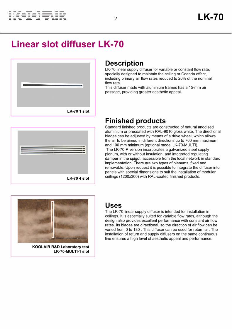
LK-70 1 slot
LK-70 4 slot
KOOLAIR R&D Laboratory test LK-70-MULTI-1 slot
Description LK-70 linear supply diffuser for variable or constant flow rate, specially designed to maintain the ceiling or Coanda effect, including primary air flow rates reduced to 20% of the nominal flow rate. This diffuser made with aluminium frames has a 15-mm air passage, providing greater aesthetic appeal.
Finished products Standard finished products are constructed of natural anodised aluminium or precoated with RAL-9010 gloss white. The directional blades can be adjusted by means of a drive wheel, which allows the air to be aimed in different directions up to 700 mm maximum and 100 mm minimum (optional model LK-70-MULTI). The LK-70-P version incorporates a galvanized steel supply plenum, with or without insulation, and integrated regulating damper in the spigot, accessible from the local network in standard implementation. There are two types of plenums, fixed and removable. Upon request it is possible to integrate the diffuser into panels with special dimensions to suit the installation of modular ceilings (1200x300) with RAL-coated finished products.
Uses The LK-70 linear supply diffuser is intended for installation in ceilings. It is especially suited for variable flow rates, although the design also provides excellent performance with constant air flow rates. Its blades are directional, so the direction of air flow can be varied from 0 to 180 . This diffuser can be used for return air. The installation of return and supply diffusers on the same continuous line ensures a high level of aesthetic appeal and performance.
Linear slot diffuser LK-70
2 LK-70

21
DV
O
MM Con MM Para
MM
Models and dimensions
LK-70 3
LK-70 with FIXED plenum without damper
LK-70 with REMOVABLE plenum without damper
OPENING= L + 15
G (OPENING)
Plenum with 1 spigot
Plenum with 2 spigots
OPENING= L + 15
Plenum with 1 spigot
Plenum with 2 spigots
G (OPENING)
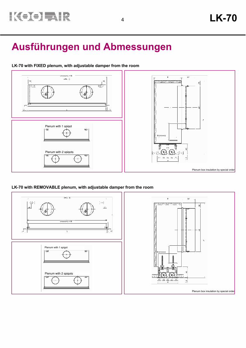
Ausführungen und Abmessungen
4 LK-70
LK-70 with FIXED plenum, with adjustable damper from the room
Plenum box insulation by special order
LK-70 with REMOVABLE plenum, with adjustable damper from the room
Plenum box insulation by special order
OPENING= L + 15
G (OPENING)
Plenum with 1 spigot
Plenum with 2 spigots
OPENING= L + 15
G (OPENING)
Plenum with 1 spigot
Plenum with 2 spigots

Models and dimensions
LK-70 5
DIMENSIONS for FIXED or REMOVABLE plenum, with or without DAMPER
SLOTS NOMINAL L
ACTIVE
LENGTH E ØD
Nº OF
SPIGOTS A B
G (OPENING) H
Standard no
deflectors
sections
1
600 600 582
124
49
72
41
225
1 900 900 882 1
2 1015 1000 997
1200 1200 1182
2 1500 1500 1482
1800 1800 1782 3 2000 2000 1982
2015 2000 1997
2
600 600 582
159
1
79
102
71
275
1 900 900 882
2 1015 1000 997
1200 1200 1182
2 1500 1500 1482
1800 1800 1782 3 2000 2000 1982
2015 2000 1997
3
600 600 582
199
109
132
101
325
1 900 900 882 1
2 1015 1000 997
1200 1200 1182
2 1500 1500 1482
1800 1800 1782 3 2000 2000 1982
2015 2000 1997
4
600 600 582
199
139
162
131
325
1 900 900 882 1
2 1015 1000 997
1200 1200 1182
2 1500 1500 1482
1800 1800 1782 3 2000 2000 1982
2015 2000 1997
LK-70 with MOUNTING BRIDGES
SLOTS G (OPENING) A 1 41 49 2 71 79 3 101 109 4 131 139
G (OPENING)

LK-70-S
Models and dimensions LK-70 / LK-70-S
6 LK-70
Nº SLOTS
L
E
Ø D
Nº SPIGOTS
A
B
C
H
1
600 597 124
49 72 41 225
900 897 124 1 1000 997 124 1200 1197 124
2 1500 1497 124
1800 1797 124 2000 1997 124
2
600 597 159
79 102 71 275
900 897 159 1 1000 997 159 1200 1197 159
2 1500 1497 159
1800 1797 159 2000 1997 159
3
600 597 199
109 132 101 325
900 897 199 1 1000 997 199 1200 1197 199
2 1500 1497 199
1800 1797 199 2000 1997 199
4
600 597 199
139 162 131 325
900 897 199 1 1000 997 199 1200 1197 199
2 1500 1497 199
1800 1797 199 2000 1997 199
LK-70-S, linear supply diffuser with narrow outer frames of 12 mm. Technical data similar to LK-70.

LK-70-L
Models and dimensions LK-70-L
LK-70 7
The linear wall diffuser model LK-70-L is specially designed for installation in continuous surface walls because it requires little space. It generates a flow of turbulent mixing air, being suitable for ranges of up to 5 m and installation heights of 2.5 to 3.5 m. To obtain an adherent vein with cold air, it is advisable not to exceed the installation distances of the diffuser with respect to the ceiling h <300 mm. If the plenum is equipped with acoustic insulation, there is no need for a silencer to avoid crosstalk.
The linear wall diffuser is available for air delivery or return, or as a combined diffuser.
The technical data of the LK-70-L model are comparable to those of the LK-70 model in horizontal drive.
It is advisable to install the plenum from the corridor and the diffuser from inside the room only once the construction of the room has been completed; so that it is therefore protected from dirt and damage during construction.
Models and dimensions
8 LK-70
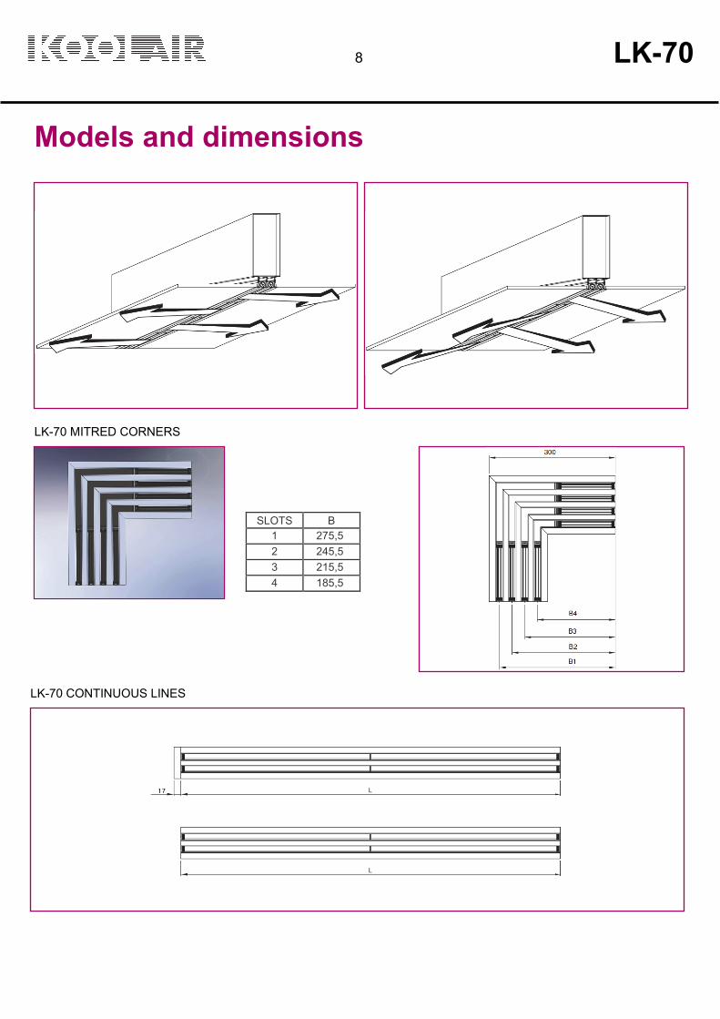
LK-70 MITRED CORNERS
LK-70 CONTINUOUS LINES
SLOTS B 1 275,5 2 245,5 3 215,5 4 185,5
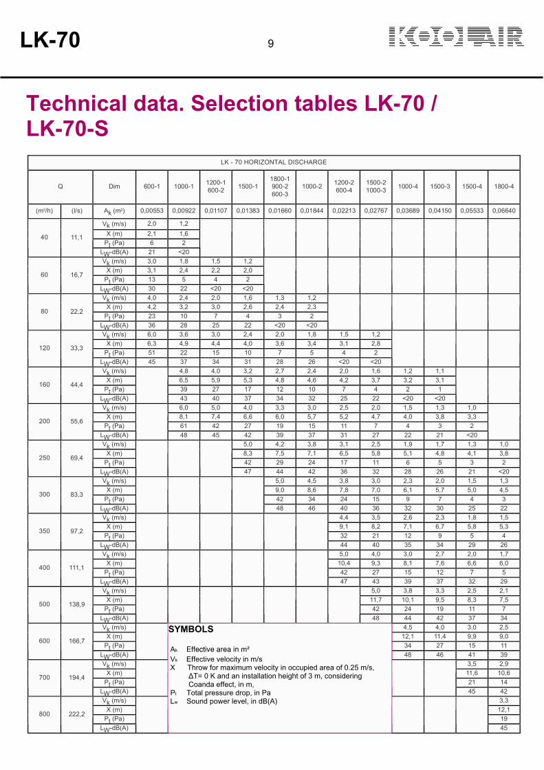
Technical data. Selection tables LK-70 / LK-70-S
LK-70 9
LK - 70 HORIZONTAL DISCHARGE
Q
Dim
600-1
1000-1
1200-1 600-2
1500-1
1800-1 900-2 600-3
1000-2
1200-2 600-4
1500-2 1000-3
1000-4
1500-3
1500-4
1800-4
(m3/h) (l/s) Ak (m2) 0,00553 0,00922 0,01107 0,01383 0,01660 0,01844 0,02213 0,02767 0,03689 0,04150 0,05533 0,06640
Vk (m/s) 2,0 1,2 X (m) 2,1 1,6
Pt (Pa) 6 2
40
11,1
LW-dB(A) 21 <20
Vk (m/s) 3,0 1,8 1,5 1,2 X (m) 3,1 2,4 2,2 2,0
Pt (Pa) 13 5 4 2
60
16,7 LW-dB(A) 30 22 <20 <20
Vk (m/s) 4,0 2,4 2,0 1,6 1,3 1,2 X (m) 4,2 3,2 3,0 2,6 2,4 2,3
Pt (Pa) 23 10 7 4 3 2
80
22,2 LW-dB(A) 36 28 25 22 <20 <20
Vk (m/s) 6,0 3,6 3,0 2,4 2,0 1,8 1,5 1,2 X (m) 6,3 4,9 4,4 4,0 3,6 3,4 3,1 2,8
Pt (Pa) 51 22 15 10 7 5 4 2
120
33,3 LW-dB(A) 45 37 34 31 28 26 <20 <20
Vk (m/s) 4,8 4,0 3,2 2,7 2,4 2,0 1,6 1,2 1,1 X (m) 6,5 5,9 5,3 4,8 4,6 4,2 3,7 3,2 3,1
Pt (Pa) 39 27 17 12 10 7 4 2 1
160
44,4 LW-dB(A)
43 40 37 34 32 25 22 <20 <20
Vk (m/s) 6,0 5,0 4,0 3,3 3,0 2,5 2,0 1,5 1,3 1,0 X (m) 8,1 7,4 6,6 6,0 5,7 5,2 4,7 4,0 3,8 3,3
Pt (Pa) 61 42 27 19 15 11 7 4 3 2
200
55,6 LW-dB(A)
48 45 42 39 37 31 27 22 21 <20
Vk (m/s) 5,0 4,2 3,8 3,1 2,5 1,9 1,7 1,3 1,0 X (m) 8,3 7,5 7,1 6,5 5,8 5,1 4,8 4,1 3,8
Pt (Pa) 42 29 24 17 11 6 5 3 2
250
69,4 LW-dB(A)
47 44 42 36 32 28 26 21 <20 Vk (m/s) 5,0 4,5 3,8 3,0 2,3 2,0 1,5 1,3
X (m) 9,0 8,6 7,8 7,0 6,1 5,7 5,0 4,5 Pt (Pa) 42 34 24 15 9 7 4 3
300
83,3
LW-dB(A)
48 46 40 36 32 30 25 22 Vk (m/s) 4,4 3,5 2,6 2,3 1,8 1,5
X (m) 9,1 8,2 7,1 6,7 5,8 5,3 Pt (Pa) 32 21 12 9 5 4
350
97,2
LW-dB(A)
44 40 35 34 29 26 Vk (m/s) 5,0 4,0 3,0 2,7 2,0 1,7
X (m) 10,4 9,3 8,1 7,6 6,6 6,0 Pt (Pa) 42 27 15 12 7 5
400
111,1
LW-dB(A)
47 43 39 37 32 29 Vk (m/s) 5,0 3,8 3,3 2,5 2,1
X (m) 11,7 10,1 9,5 8,3 7,5 Pt (Pa) 42 24 19 11 7
500
138,9
LW-dB(A)
48 44 42 37 34 Vk (m/s) 4,5 4,0 3,0 2,5
X (m) 12,1 11,4 9,9 9,0 Pt (Pa) 34 27 15 11
600
166,7
LW-dB(A)
48 46 41 39 Vk (m/s) 3,5 2,9
X (m) 11,6 10,6 Pt (Pa) 21 14
700
194,4
LW-dB(A)
45 42 Vk (m/s) 3,3
X (m) 12,1 Pt (Pa) 19
800
222,2
LW-dB(A)
SYMBOLS Ak Effective area in m² Vk Effective velocity in m/s X Throw for maximum velocity in occupied area of 0.25 m/s, ∆T= 0 K and an installation height of 3 m, considering Coanda effect, in m, Pt Total pressure drop, in Pa Lw Sound power level, in dB(A)
45

10 LK-70
Technical data. Selection tables LK-70 / LK-70-S
LK - 70 VERTICAL DISCHARGE
Q
Dim
600-1
1000-1
1200-1 600-2
1500-1
1800-1 900-2 600-3
1000-2
1200-2 600-4
1500-2 1000-3
1000-4
1500-3
1500-4
1800-4
(m3/h) (l/s) Ak (m2) 0,00581 0,00968 0,01162 0,01452 0,01742 0,01936 0,02323 0,02904 0,03872 0,04356 0,05808 0,06969 Vk (m/s) 2,4
Ymáx (m) 1,2 Pt (Pa) 5
50
13,9
LW-dB(A) <20
Vk (m/s 3,6 2,2 1,8 Ymáx (m) 1,9 1,2 1,0
Pt (Pa) 10 5 3
75
20,8 LW-dB(A) 27 <20 <20
Vk (m/s 4,8 2,9 2,4 1,9 Ymáx (m) 2,5 1,6 1,4 1,2
Pt (Pa) 19 8 6 4
100
27,8 LW-dB(A) 33 25 22 <20
Vk (m/s 6,7 4,0 3,3 2,7 2,2 2,0 1,7 Ymáx (m) 3,5 2,2 1,9 1,6 1,4 1,3 1,2
Pt (Pa) 36 16 11 7 5 4 3
140
38,9 LW-dB(A) 41 33 30 22 <20 <20 <20
Vk (m/s 8,6 5,2 4,3 3,4 2,9 2,6 2,2 1,7 Ymáx (m) 4,5 2,9 2,5 2,1 1,8 1,7 1,5 1,3
Pt (Pa) 60 26 18 12 8 7 5 3
180
50,0 LW-dB(A) 47 39 36 28 25 24 21 <20
Vk (m/s 6,9 5,7 4,6 3,8 3,4 2,9 2,3 1,7 1,5 Ymáx (m) 3,8 3,3 2,8 2,4 2,3 2,0 1,7 1,3 1,2
Pt (Pa) 47 32 21 14 12 8 5 3 2
240
66,7 LW-dB(A)
46 43 35 32 31 28 24 <20 <20
Vk (m/s 7,2 5,7 4,8 4,3 3,6 2,9 2,2 1,9 1,4 1,2 Ymáx (m) 4,2 3,5 3,1 2,8 2,5 2,1 1,7 1,5 1,2 1,0
Pt (Pa) 51 32 22 18 13 8 5 4 2 1
300
83,3 LW-dB(A)
48 41 38 36 33 30 25 24 <20 <20 Vk (m/s 6,4 5,7 4,8 3,8 2,9 2,6 1,9 1,6
Ymáx (m) 4,1 3,8 3,3 2,8 2,2 2,1 1,5 1,3 Pt (Pa) 40 32 22 14 8 6 4 2
400
111,1
LW-dB(A)
7,7 4,7 57 48 45 43 40 37 32 31 26 23
Vk (m/s 7,2 6,0 4,8 3,6 3,2 2,4 2,0 Ymáx (m) 4,7 4,2 3,5 2,8 2,6 1,9 1,7
Pt (Pa) 51 35 22 13 10 6 4
500
138,9 LW-dB(A)
49 46 42 38 36 32 29 Vk (m/s 5,7 4,3 3,8 2,9 2,4
Ymáx (m) 4,2 3,4 3,1 2,3 2,0 Pt (Pa) 32 18 14 8 6
600
166,7
LW-dB(A)
47 42 41 36 33 Vk (m/s 5,0 4,5 3,3 2,8
Ymáx (m) 3,9 3,6 2,7 2,3 Pt (Pa) 25 20 11 8
700
194,4
LW-dB(A)
46 44 40 37 Vk (m/s 5,1 3,8 3,2
Ymáx (m) 4,1 3,1 2,7 Pt (Pa) 26 14 10
800
222,2
LW-dB(A)
48 43 40 Vk (m/s 4,3 3,6
Ymáx (m) 3,5 3,0 Pt (Pa) 18 13
900
250,0
LW-dB(A)
46 43 Vk (m/s 4,0
Ymáx (m) 3,3 Pt (Pa) 16
1000
277,8
LW-dB(A)
SYMBOLS Ak Effective area in m² Vk Effective velocity in m/s Ymax Maximum vertical throw of air jet for ∆T = 10 K (in heating) Pt Total pressure drop, in Pa Lw Sound power level, in dB(A)
46

Technical data. Selection graphs LK-70 / LK-70-S
LK-70 11
Graph 1. SOUND LEVEL, HORIZONTAL DISCHARGE
HORIZONTAL AIR SUPPLY
Effective width of slot hk = 0,009222 m
Effective diffuser area Ak (m2) = hk x L (m) x nº slots
L = Nominal length of diffuser (active length)

Technical data. Selection graphs LK-70 / LK-70-S
12 LK-70
Graph 2. SOUND LEVEL, VERTICAL DISCHARGE
VERTICAL SUPPLY
Effective width of slot hk = 0,009679 m
Effective diffuser area Ak (m2) = hk x L (m) x Schlitzzahl
L = Nominal length of diffuser (active length)

LK-70 13
Technical data. Selection graphs LK-70 / LK-70-S

14 LK-70
Technical data. Selection graphs LK-70 / LK-70-S Graph 4. VERTICAL DISCHARGE
Dim [L(mm) - - nº slots]

LK-70 15
B Distance between diffuser axes (m) hR Height from ceiling to occupied area (m) VhR Velocity at a distance hR from the ceiling below the point where air jets meet (m/s)
Technical data. Selection graphs LK-70 / LK-70-S Graph 5. AIR STREAM BETWEEN DIFFUSERS
D
imen
sio
n

16 LK-70
Technical data. Selection graphs LK-70 / LK-70-S Graph 6. AIR STREAM TOWARD THE WALL
L Horizontal distance from diffuser to wall + hR VL Velocity at the wall, at a distance hR from the ceiling
Dim [L(mm) - - nº slots]
LK-70 17
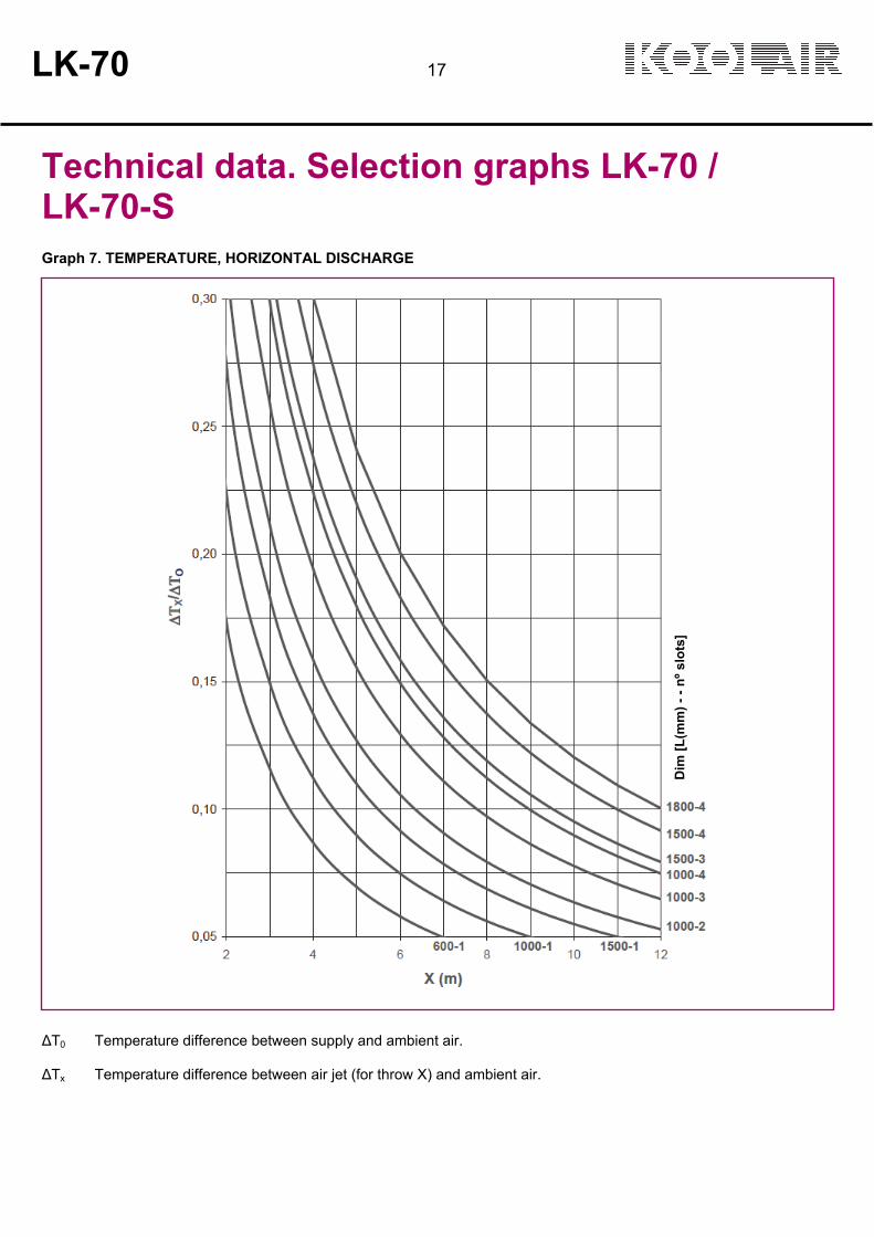
Technical data. Selection graphs LK-70 / LK-70-S Graph 7. TEMPERATURE, HORIZONTAL DISCHARGE
∆T0 Temperature difference between supply and ambient air. ∆Tx Temperature difference between air jet (for throw X) and ambient air.
Dim
[L
(mm
) -
- n
º sl
ots
]

18 LK-70
Technical data. Selection graphs LK-70 / LK-70-S Graph 8. TEMPERATURE, VERTICAL DISCHARGE
Dim
[L
(mm
) -
- n
º sl
ots
]

LK-70 19
Technical data. Selection graphs LK-70 / LK-70-S Graph 9. INDUCTION RATE, HORIZONTAL DISCHARGE
qx/qo Induction rate. Quotient between the air volume moved by the air jet for a throw X and the supply air volume.
Dim
[L
(mm
) -
- n
º sl
ots
]

20 LK-70
Technical data. Selection graphs LK-70 / LK-70-S Graph 10. INDUCTION RATE, VERTICAL DISCHARGE
Dim
[L
(mm
) -
- n
º sl
ots
]

LK-70 21
Selection examples
Example 1. Horizontal Air Supply
The selection of an LK-70 linear diffuser is planned with the following design input: •Flow rate: 145 m3/h •Sound power < 35 dB(A) •Ceiling height: 3 m •Distance from the diffuser to the wall is 2.8 m •Distance between the diffusers (in the direction of the air supply): 5 m
Starting with Graph 1 with a flow rate of 145 m3/h, we see that the sound power is 35 dB(A) for an LK 70 1500 – 1-slot linear diffuser, with a drop in pressure of 14 Pa. In order to obtain the effective velocity (Vk), we must first know the effective area of the diffuser (Ak). In this case, it appears in the table for selecting the horizontal air supply, but it can also be calculated by applying the formula shown in the table on page 9, as follows:
Ak = 0,009222 m x 1,5 m x 1 = 0.01383 m2
Thus, the effective output velocity (Vk) for the diffuser will be equal to:
145 m3/h / (3600 s/h) V
k = = 2,9 m/s
0,01383 m2
In order to obtain the required throw of an LK 70 1500 1-slot diffuser with an air flow rate of 145 m3/h, we need to look at Graph 3; for a maximum velocity of 0.25 m/s in an occupied area, we arrive at a throw of 4.8 m under isothermal conditions. The maximum velocity in an occupied area generated by the air collision between diffusers can be obtained in Graph 5. Starting with an air flow rate of 145 m3/h, the distance between the axles 8 m = 1.2 m) we arrive at a velocity of VhR = 0.24 m/s. In order to determine the velocity in the wall area, with the diffuser installed in the wall at a height of 2.8 m, we need to look at Graph 6 with an air flow rate of 145 m3/h. The length L to be considered for calculating the velocity at a height from the floor of 1.8 m will be: L = 2,8 + (3 – 1,8) = 4 m Using these data, we obtain a velocity at this point of V
L = 0,38 m/s.

22 LK-70
Selection examples
Example 2. Vertical Air Supply
An LK-70 linear diffuser is selected based on the following design input data:
•Flow rate: 330 m3/h •Sound power < 35 dB(A) •Maximum vertical penetration: 3 m •∆T = +6 K
Starting with Graph 4 with a flow rate of 330 m3/h we observe that, for a size 1000 three-slots LK-70 diffuser and a ∆T = +6 K, we obtain a maximum penetration of Ymax = 3 m. In order to obtain the sound output level and the drop in pressure for the selected diffuser, we need to look at Graph 2 with an air flow rate of 330 m3/h. We obtain a sound power level of 33 dB(A) and a pressure drop of 11 Pa. In order to obtain the effective velocity (Vk), we must first know the effective area of the diffuser (Ak). In this case, it appears in the vertical air supply selection table, but it can also be calculated by applying the formula shown in the table on page 9, as follows:
Ak = 0,009679 m x 1m x 3 = 0,029037 m2
Thus, the effective output velocity (Vk) for the diffuser will be equal to::
330 m3/h / (3600 s/h) V
k = = 3,2 m/s
0,029037 m2

Product code
The product code shown below is used to define both the diffuser as well as the plenum:
LK-70 Linear diffuser LK-70-S Linear diffuser of narrow outer frame LK-70-MULTI Linear diffuser with slats of minimum length 100 mm LK-70-L Linear wall diffuser 1-2-3-4 Number of slots --- length of the diffuser (nominal, opening in mm)
--- no. of STANDARD lengths of deflector blades A no. of spans to define: (type LK-70-MULTI)
(minimum 100 mm maximum 700 mm)
PM Mounting bridge
PF Fixed plenum without damper PD Removable plenum without damper
PF-C Fixed plenum with damper PD-C Removable plenum with damper
PFA Insulated fixed plenum without damper PDA Insulated removable plenum without damper
PFA-C Insulated fixed plenum with damper PDA-C Insulated removable plenum with damper
RAL 9010 Standard finished product in white RAL... Finished product in another RAL coating
Example:
LK-70-1-1200-PFA-C RAL 9010
LK-70 linear diffuser, one-slot, and
nominal width 1200 mm, 2 lengths of
blades (standard), with insulated fixed
plenum and integrated regulating
damper in the spigot, coated in
RAL-9010 white.
LK-70 23

LK-70-C - 125 - 1000 - 2 slots
LK-70-C - 315 - 1000 - 6 slots
LK-70-C
Linear slot diffuser integrated into a circular duct LK-70-C
Description Supply linear slot diffuser, model LK-70-C, suitable for variable and constant volume. Integrated into a circular duct this diffuser frames has a 17-mm air passage, providing greater aesthetic appeal. The diffuser is suitable for large airflows at low velocities into the occupied zone. Recommended installation height between 2.5 and 4m.
Finished products Standard finished products are made in galvanised sheet steel or painted in RAL-9010 gloss white equipped with adjustable blades manufactured in aluminium extrusion. The directional blades can be adjusted by means of a drive wheel, which allows the air to be aimed in different directions. To ensure the correct balance of the installation the diffuser incorporates a sliding damper, which also equalizes the air stream. It is possible to install a certain number of diffuser sections to form continuous lines of a certain length, using connecting flanges. It can provide blind and duct sections "T" or "L" to 90º. Upon request it is possible to supply other accessories.
Uses The LK-70-C linear supply diffuser is intended for installation in circular duct. It is especially suited for variable flow rates, although the design also provides excellent performance with constant air flow rates. Its blades are directional, so the direction of air flow can be varied from 0º to 180º. This diffuser can be used for return air. The installation of return and supply diffusers on the same continuous line ensures a high level of aesthetic appeal and performance. For supply the diffuser are supplied without blades
24 LK-70

Models and dimensions
NOMINAL D125 1 2 - - - - - - - - - - - - 123160 1 2 3 4 - - - - - - - - - - 158200 1 2 3 4 - - - - - - - - - - 198225 1 2 3 4 - - - - - - - - - - 223250 1 2 3 4 - - - - - - - - - - 248300 1 2 3 4 5 6 - - - - - - - - 298315 1 2 3 4 5 6 - - - - - - - - 313355 1 2 3 4 5 6 7 8 - - - - - - 353400 1 2 3 4 5 6 7 8 - - - - - - 398450 1 2 3 4 5 6 7 8 - - - - - - 448500 1 2 3 4 5 6 7 8 9 10 11 12 13 14 498630 1 2 3 4 5 6 7 8 9 10 11 12 13 14 628710 1 2 3 4 5 6 7 8 9 10 11 12 13 14 708800 1 2 3 4 5 6 7 8 9 10 11 12 13 14 798900 1 2 3 4 5 6 7 8 9 10 11 12 13 14 898
L 500 750 1000 1250 1500 1750 2000No. OF SLOTS 3 4 6 7 8 10 12
No. OF SECTIONS
No. OF SLOTS
1 2
LK-70 25

Models and dimensions
Air direction options
Horizontal one direction
Horizontal two directions
Vertical
Blades position
Number of segments per length
26 LK-70
ORIENTATION 90º
ORIENTATION 2x90º ORIENTATION 180º
ORIENTATION 135º
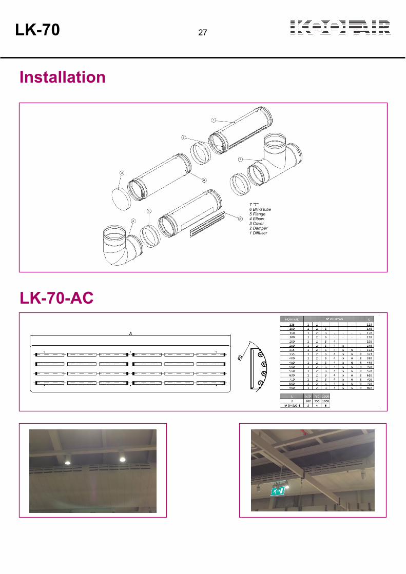
Installation
LK-70-AC
LK-70 27
7 "T" 6 Blind tube 5 Flange 4 Elbow 3 Cover 2 Damper 1 Diffuser
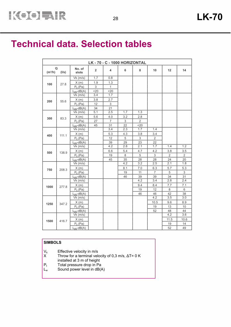
Technical data. Selection tables
LK - 70 - C - 1000 HORIZONTAL Q
(m3/h) (l/s) No. of slots
2
4
6
8
10
12
14
Vk (m/s) 1.7 0.8 X (m) 1.9 1.3
Pt (Pa) 3 1
100
27.8 LW-dB(A) <20 <20
Vk (m/s) 3.4 1.7 X (m) 3.8 2.7
Pt (Pa) 12 3
200
55.6 LW-dB(A) 34 21
Vk (m/s) 5.1 2.5 1.7 1.3 X (m) 5.6 4.0 3.2 2.8
Pt (Pa) 27 7 3 2
300
83.3 LW-dB(A) 45 31 22 <20
Vk (m/s) 3.4 2.3 1.7 1.4 X (m) 5.3 4.3 3.8 3.4
Pt (Pa) 12 5 3 2
400
111.1 LW-dB(A)
39 29 23 22
Vk (m/s) 4.2 2.8 2.1 1.7 1.4 1.2 X (m) 6.6 5.4 4.7 4.2 3.8 3.5
Pt (Pa) 19 8 5 3 2 2
500
138.9 LW-dB(A)
45 35 28 28 24 20 Vk (m/s) 4.2 3.2 2.5 2.1 1.8
X (m) 8.1 7.0 6.3 5.7 5.3 Pt (Pa) 19 11 7 5 3
750
208.3 LW-dB(A)
46 39 39 34 31 Vk (m/s) 4.2 3.4 2.8 2.4
X (m) 9.4 8.4 7.7 7.1 Pt (Pa) 19 12 8 6
1000
277.8 LW-dB(A)
46 46 42 38 Vk (m/s) 4.2 3.5 3.0
X (m) 10.5 9.6 8.9 Pt (Pa) 19 13 10
1250
347.2 LW-dB(A)
52 48 44 Vk (m/s) 4.2 3.6
X (m) 11.5 10.6 Pt (Pa) 19 14
1500
416.7 LW-dB(A)
52 49
SIMBOLS Vk Effective velocity in m/s X Throw for a terminal velocity of 0,3 m/s, ∆T= 0 K
installed at 3 m of height Pt Total pressure drop in Pa Lw Sound power level in dB(A)
28 LK-70

Technical data. Selection graphs
PRESSURE DROP AND SOUND LEVEL
HORIZONTAL THROW
Q (m3/h) = kQ x Qgraph Vt (m/s) = kVt x Vtgraph
TEMPERATURE, HORIZONTAL DISCHARGE
INDUCTION RATE, HORIZONTAL DISCHARGE
LK-70 29
Nº of slots
Nº
of
slo
ts
Nº
of
slo
ts
Correction for Airflow duct length
Length (mm)
Terminal velocity correction for number of slots

Product code
The product code shown below is used to define both the diffuser as well as the plenum:
LK-70-C Linear slot diffuser integrated into a circular duct LK-70-AC Linear slot diffuser integrated in a circular adaptation Ø 125 to 900 mm 500 .. xx Length 1 .. xx No. of slots
V Blades at vertical discharge position H Blades at horizontal discharge position H2 Blades at double horizontal discharge position D Blades at diagonal discharge position
--- No cover T Cover without fixing TF Cover fixing with bracket B Flange C Blind tube without fixing CF90 Blind tube with integrated fixing at 90º CF180 Blind tube with integrated fixing at 180º T90 "T" at 90º L90 "L" at 90º
RAL 9010 Standard finished product in white RAL... Finished product in another RAL coating
Example: LK-70-C-125-1000-2-H-T-RAL 9010 Linear slot diffuser integrated into a circular duct, Ø125 mm and 1000 mm length, blades at horizontal discharge position and cover without fixing, painted in white RAL 9010 gloss.
Technical Specification Linear slot diffuser integrated into a circular duct, model LK-70-C, suitable for variable and constant volume with adjustable blades adjusted by means of a drive wheel. Standard finished products are made in galvanised sheet steel or painted in RAL-9010 gloss white. Blades manufactured in aluminium extrusion, standard finished in black. The diffuser incorporates a sliding damper accesible from room.
30 LK-70
THIS CATALOGUE IS INTELLECTUAL PROPERTY. Reproduction, either partial or total, by any means, including electronic, is prohibited without prior written authorisation from KOOLAIR, S.L.
CIN-LK70-0908-01
LK-70 31

KOOLAIR, S.L.
Calle Urano, 26Poligono industrial nº 2 – La Fuensanta 28936 Móstoles - Madrid - (España) Tel: +34 91 645 00 33Fax: +34 91 645 69 62e-mail: [email protected]
www.koolair.com


