Installation Instructions Valve should be installed and adjusted b y a licensed contractor in accordance with local codes and ordinances. Further, this valve should be installed in a location where it is accessible or cleaning, service or adjustment. 1. Close both the hot and cold water shutovalves upstream nearest to the intended installation. 2. Bleed the remaining water rom the system. 3. Connect the water supply to valve as shown in Figure 1, 2 or 3 depending on appli- cation. Supply piping must be lushed clean beore making connections to the valve. 4. Valve can be installed in any position. Note: the inlet hot supply i s to be connected to the “H” side othe valve, the cold supply side to the “C” side and the mixed water outlet to the “M” side. 5. Make sure union nuts are placed over tailpieces prior to soldering or threading to pipe. 6. For valves with Quick-Connect tailpieces reer to "Quick-Connect Installation" instructions below Note: To prevent damage to valve rom excessive heat during soldering, remove unions and gaskets rom valve body prior to soldering. 7. Ater soldering, lush piping and i nstall valve using ilter washer on hot and cold water inlet and iber washer on the mixed water outlet. 8. Start-up: Open cold water supply, then hot water supply. Inspect or leaks. 9. Adjust temperature to desired setting (see Temperature Adjustment Section). Watt s recommends a maximum temperature o110°F (43°C) or shower and bathing ixtures. Series MMV and LFMMVThermostatic Tempering Valves Sizes: 1 ⁄ 2", 3 ⁄ 4", 1" (15, 20, 25mm) IS-MMV-M1 LFMMV-UT-M1 MMV-QC-M1 Quick-Connect Installation 1. Mark pipe as shown. This is pipe insertion depth. 2. Clean pipe end. 1. Remove collet clip. 2. Depress collet. 3. Pull tubing rom tailpiece. 3. Iusing PEX tubing, insert pipe stiener (provided) into end opipe. 4. Push tubing into tailpiece up to mark. 5. Insert collet clip. To Connect To Disconnect PEX tubing only Pipe Stiffener Tail Piece MarkCollet clip Collet depressed 1 1 /2 in. (38.1mm) 1 3 /4 in. (44.45mm) 1 7 /8 in. (47.63mm) 1 /2 in.Pipe (12.7mm) 3 /4 in.Pipe (19.05mm) 1 in.Pipe (25.4mm) Figure 1 – Typical ASSE 1069 Application Typical MMV-M1 and LFMMV-M1 Applications Cold Hot MMV-M1 or LFMMV-M1 Mixed Triple Listed! ASS E 1017 , ASSE 1069 & ASSE 1070
Transcript
8/8/2019 Series MMV and LFMMV Installation Instructions
Installation Instructions Valve should be installed and adjusted by a licensed contractor in accordance withlocal codes and ordinances. Further, this valve should be installed in a location where
it is accessible or cleaning, service or adjustment.1. Close both the hot and cold water shuto valves upstream nearest to the intended
installation.
2. Bleed the remaining water rom the system.
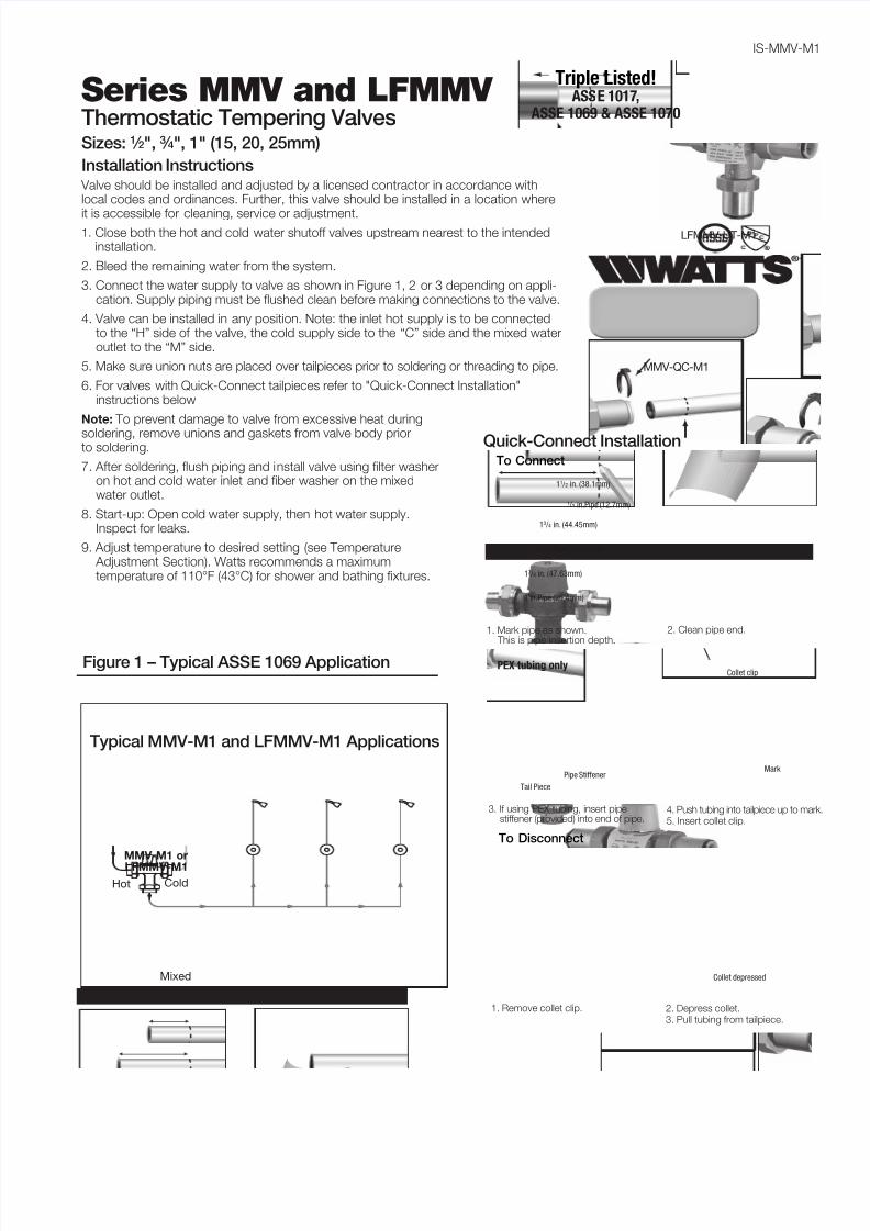
3. Connect the water supply to valve as shown in Figure 1, 2 or 3 depending on appli-cation. Supply piping must be lushed clean beore making connections to the valve.
4. Valve can be installed in any position. Note: the inlet hot supply is to be connectedto the “H” side o the valve, the cold supply side to the “C” side and the mixed wateroutlet to the “M” side.
5. Make sure union nuts are placed over tailpieces prior to soldering or threading to pipe.
6. For valves with Quick-Connect tailpieces reer to "Quick-Connect Installation"instructions below
Note: To prevent damage to valve rom excessive heat during
soldering, remove unions and gaskets rom valve body priorto soldering.
7. Ater soldering, lush piping and install valve using ilter washeron hot and cold water inlet and iber washer on the mixedwater outlet.
8. Start-up: Open cold water supply, then hot water supply.Inspect or leaks.
9. Adjust temperature to desired setting (see Temperature Adjustment Section). Watts recommends a maximumtemperature o 110°F (43°C) or shower and bathing ixtures.
Series MMV and LFMMV Thermostatic Tempering ValvesSizes: 1 ⁄ 2", 3 ⁄ 4", 1" (15, 20, 25mm)
IS-MMV-M
LFMMV-UT-M1
MMV-QC-M1
Quick-Connect Installation
1. Mark pipe as shown. This is pipe insertion depth.
This valve requires periodic inspection and veriication o the out-let temperature by a licensed contractor. Corrosive water condi-tions, hot inlet water temperature over 200°F (93°C), unauthor-ized adjustments or repairs could render the valve ineective orits intended service. Regular cleaning and checking o thermo-stat assembly helps to maximize valve lie and Tempering unc-tion. Frequency o cleaning depends on local water conditions.
NOTE: It is recommended that shuto valve(s) be installed onthe inlet(s) to acilitate service o the MMV-M1 or LFMMV-M1
cold inlet, 39°F – 85°F (4°C – 29°C)Hot Water Inlet to Outlet Differential Temperature: 5°F (3°C)Temperature Out: Field range: 80°F – 120°F (27°C – 49°C),
adjustable; Accurate within ±3°F (1.7°C)Maximum Temperature: 200°F (93°C)Maximum Pressure: 150psi (1034 kPa)Minimum Flow: 0.5 gpm (1.9 lpm) @.08psi (0.55 kPa)†
Maximum Flow: 20 gpm (76 lpm) @ 125psi (862 kPa)†
Maximum Pressure Differential betweenHot & Cold Water Supplies: 25%
Listing: ASSE 1017, ASSE 1069, ASSE 1070 and IAPMO cUPC
† When tested in accordance with ASSE 1017, ASSE 1069, ASSE 1070
and IAPMO cUPC.
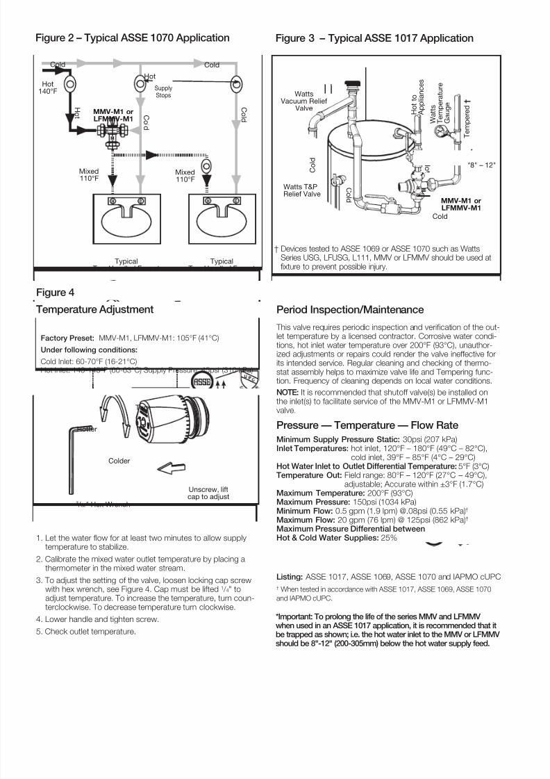
Figure 4
Temperature Adjustment
1. Let the water low or at least two minutes to allow supply
temperature to stabilize.
2. Calibrate the mixed water outlet temperature by placing athermometer in the mixed water stream.
3. To adjust the setting o the valve, loosen locking cap screwwith hex wrench, see Figure 4. Cap must be lited 1 / 4" toadjust temperature. To increase the temperature, turn coun-terclockwise. To decrease temperature turn clockwise.
† Devices tested to ASSE 1069 or ASSE 1070 such as WattsSeries USG, LFUSG, L111, MMV or LFMMV should be used atixture to prevent possible injury.
Watts Vacuum Relief
Valve
W a t t s
T e m p e r a t u r e
G a u g e
C ol d
Cold
C o l d
MMV-M1 or
LFMMV-M1
T
e m p e r e d †
H ot
H o t t o
A p p l i a n c e s
Watts T&PRelief Valve
*8" – 12"
H
C
M
Figure 3 – Typical ASSE 1017 Application
Hotter
3 / 32" Hex Wrench
Turn
Colder
Unscrew, liftcap to adjust
*Important: To prolong the life of the series MMV and LFMMV when used in an ASSE 1017 application, it is recommended that itbe trapped as shown; i.e. the hot water inlet to the MMV or LFMMV should be 8"-12" (200-305mm) below the hot water supply feed.
8/8/2019 Series MMV and LFMMV Installation Instructions
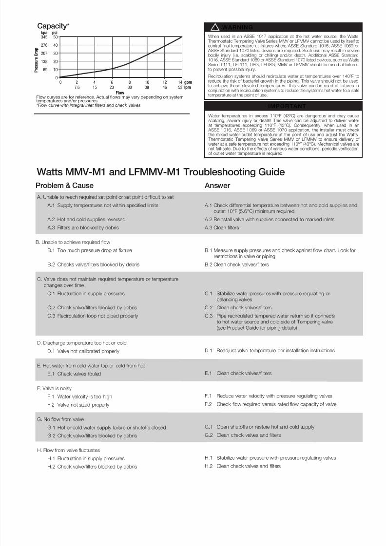
Flow curves are for reference. Actual flows may vary depending on systemtemperatures and/or pressures.*Flow curve with integral inlet filters and check valves
Capacity* kpa psi345 50
276 40
207 30
138 20
69 10
00 2 4 6 8 10 12 14 gpm
7.6 15 23 30 38 46 53 lpm
P r e s s u r e D r o p
Flow
Watts MMV-M1 and LFMMV-M1 Troubleshooting Guide
Problem & Cause
A. Unable to reach required set point or set point di icult to set
A.1 Supply temperatures not within speciied limits
A.2 Hot and cold supplies reversed
A.3 Filters are blocked by debris
B. Unable to achieve required low
B.1 Too much pressure drop at ixture
B.2 Checks valve/ilters blocked by debris
C. Valve does not maintain required temperature or temperature
changes over timeC.1 Fluctuation in supply pressures
C.2 Check valve/ilters blocked by debris
C.3 Recirculation loop not piped properly
D. Discharge temperature too hot or cold
D.1 Valve not calibrated properly
E. Hot water rom cold water tap or cold rom hot
E.1 Check valves ouled
F. Valve is noisy
F.1 Water velocity is too high
F.2 Valve not sized properly
G. No ow rom valve
G.1 Hot or cold water supply ailure or shutos closed
G.2 Check valve/ilters blocked by debris
H. Flow rom valve uctuates
H.1 Fluctuation in supply pressures
H.2 Check valve/flters blocked by debris
Answer
A.1 Check dierential temperature between hot and cold supplies and
outlet 10°F (5.6°C) minimum required
A.2 Reinstall valve with supplies connected to marked inlets
A.3 Clean ilters
B.1 Measure supply pressures and check against low chart. Look or
restrictions in valve or piping
B.2 Clean check valves/ilters
C.1 Stabilize water pressures with pressure regulating or
balancing valves
C.2 Clean check valves/ilters
C.3 Pipe recirculated tempered water return so it connects
to hot water source and cold side o Tempering valve
(see Product Guide or piping details)
D.1 Readjust valve temperature per installation instructions
E.1 Clean check valves/ilters
F.1 Reduce water velocity with pressure regulating valves
F.2 Check low required versus rated low capacity o valve
G.1 Open shutos or restore hot and cold supply
G.2 Clean check valves and ilters
H.1 Stabilize water pressure with pressure regulating valves
H.2 Clean check valves and ilters
Water temperatures in excess 110ºF (43ºC) are dangerous and may causescalding, severe injury or death! This valve can be adjusted to deliver waterat temperatures exceeding 110ºF (43ºC). Consequently, when used in an
ASSE 1016, ASSE 1069 or ASSE 1070 application, the installer must check the mixed water outlet temperature at the point o use and adjust the Watts
Thermostatic Tempering Valve Series MMV or LFMMV to ensure delivery o water at a sae temperature not exceeding 110ºF (43ºC). Mechanical valves arenot ail-sae. Due to the eects o various water conditions, periodic veriicationo outlet water temperature is required.
When used in an ASSE 1017 application at the hot water source, the Watts Thermostatic Tempering Valve Series MMV or LFMMV cannot be used by itsel tocontrol inal temperature at ixtures where ASSE Standard 1016, ASSE 1069 or
ASSE Standard 1070 listed devices are required. Such use may result in severebodily injury (i.e. scalding or chilling) and/or death. Additional ASSE Standard1016, ASSE Standard 1069 or ASSE Standard 1070 listed devices, such as WattsSeries L111, LFL111, USG, LFUSG, MMV or LFMMV should be used at ixturesto prevent possible injury.
Recirculation systems should recirculate water at temperatures over 140ºF toreduce the risk o bacterial growth in the piping. This valve should not be usedto achieve these elevated temperatures. This valve can be used at ixtures inconjunction with recirculation systems to reduce the system’s hot water to a sae
temperature at the point o use.
IMPORTANT
WARNING!
8/8/2019 Series MMV and LFMMV Installation Instructions
ATTENTION INSTALLER: After installation, please leave thisInstruction Sheet for occupant’s information.IMPORTANT: Inquire with governing authorities for localinstallation requirements.
Limited Warranty: Watts Regulator Co. (the “Company”) warrants each product to be free from defects in material and workmanship under normal usage for a period of one year from the date of
original shipment. In the event of such defects within the warranty period, the Company will, at its option, replace or recondition the product without charge.THE WARRANTY SET FORTH HEREIN IS GIVEN EXPRESSLY AND IS THE ONLY WARRANTY GIVEN BY THE COMPANY WITH RESPECT TO THE PRODUCT. THE COMPANY MAKES NO OTHERWARRANTIES, EXPRESS OR IMPLIED. THE COMPANY HEREBY SPECIFICALLY DISCLAIMS ALL OTHER WARRANTIES, EXPRESS OR IMPLIED, INCLUDING BUT NOT LIMITED TO THE IMPLIEDWARRANTIES OF MERCHANTABILITY AND FITNESS FOR A PARTICULAR PURPOSE.The remedy described in the first paragraph of this warranty shall constitute the sole and exclusive remedy for breach of warranty, and the Company shall not be respons ible for any incidental, specialor consequential damages, including without limitation, lost profits or the cost of repairing or replacing other property which is damaged if this product does not work properly, other costs resultingfrom labor charges, delays, vandalism, negligence, fouling caused by foreign material, damage from adverse water conditions, chemical, or any other circumstances over which the Company has nocontrol. This warranty shall be invalidated by any abuse, misuse, misapplication, improper installation or improper maintenance or alteration of the product.Some States do not allow limitations on how long an implied warranty lasts, and some States do not allow the exclusion or limitation of incidental or consequential damages. Therefore the abovelimitations may not apply to you. This Limited Warranty gives you specific legal rights, and you may have other rights that vary from State to State. You should consult applicable state laws todetermine your rights. SO FAR AS IS CONSISTENT WITH APPLICABLE STATE LAW, ANY IMPLIED WARRANTIES THAT MAY NOT BE DISCLAIMED, INCLUDING THE IMPLIED WARRANTIES OFMERCHANTABILITY AND FITNESS FOR A PARTICULAR PURPOSE, ARE LIMITED IN DURATION TO ONE YEAR FROM THE DATE OF ORIGINAL SHIPMENT.