77
Series PM130 PLUS Powermeters PM130P/PM130E/PM130EH Modbus Communications Protocol Reference Guide BG0427 Rev. A6

Series PM130 PLUS Powermeters
PM130P/PM130E/PM130EH
Modbus Communications Protocol
Reference Guide
BG0427 Rev. A6

2
Every effort has been made to ensure that the material herein is complete and accurate. However, the manufacturer is not responsible for any mistakes in printing or faulty instructions contained in this book. Notification of any errors or misprints will be received with appreciation.
For further information regarding a particular installation, operation or maintenance of equipment, contact the manufacturer or your local representative or distributor.
REVISION HISTORY
A1 Nov 2007 Release
A2 Dec 2009 F/W versions 11.1.6 or higher. Added DNP 16-bit and 32-bit frozen binary counter and analog input objects. Added DNP Object 50 Time and Date to the Class 0 point list. F/W versions 11.1.11 or higher.
Added TCP event notification client. Added GPRS setup and communication counters. Added time triggers. Added DI change event log. F/W versions 11.2.1 or higher. Added 8 tariffs. F/W versions 11.3.1 or higher. Added event and data log setup and file transfer registers.
A3 Oct 2010 F/W versions 11.3.3 or higher. Added kVAh import/export and 4-quadrant kvarh registers.
A4 Jan 2013 Added support for the 12DI/4RO module and IEC 60870 setup.
A5 June 2017 Added WiFi module support.
A6 Nov 2017 Added “1LL3” wiring configuration support.
Modbus is a trademark of Schneider Electric.

3
Table of Contents
1 GENERAL........................................................................................................... 8
2 MODBUS PROTOCOL IMPLEMENTATION ...................................................... 9
2.1 Transmission Modes ......................................................................................... 9 2.2 Address Field ................................................................................................... 9 2.3 Function Field................................................................................................... 9 2.4 Exception Responses ........................................................................................ 9 2.5 Transaction Timing .......................................................................................... 9 2.6 Modbus Register Addresses ........................................................................... 10 2.7 Data Formats ................................................................................................. 10 2.7.1 16-bit Scaled Integer Format .................................................................................. 10 2.7.2 32-bit Long Integer Format .................................................................................... 11 2.7.3 32-bit Floating Point Format ................................................................................... 12 2.7.4 32-bit Modulo-10000 Format .................................................................................. 12 2.8 User Assignable Registers .............................................................................. 12 2.9 Password Protection ...................................................................................... 13 2.10 Data Recording and File Transfers ................................................................. 13 2.10.1 Log File Organization ...................................................................................... 13
Multi-section Files ................................................................................................. 13 Data Log File ........................................................................................................ 14 Profile Data Log File .............................................................................................. 14 Real-time Waveforms ............................................................................................ 14
2.10.2 File Transfers .................................................................................................. 14 Common File Transfer ........................................................................................... 14 Reading Multi-section Data Log Files ....................................................................... 15 Reading Real-time Waveforms ................................................................................ 16
2.11 TCP Notification Client ................................................................................... 16
3 MODBUS REGISTER MAP .............................................................................. 18
3.1 Modbus Setup Registers ................................................................................. 18 Assignable Modbus Registers .................................................................................. 18 Assignable Registers Map....................................................................................... 18 Modbus Conversion Scales ..................................................................................... 18 Device Data Scales ............................................................................................... 18 32-bit Register Type ............................................................................................. 18
3.2 16-bit Scaled Analog Registers and Energy Counters - Basic Register Set...... 19 3.3 16-bit Scaled Analog Registers, Binary Registers and Counters ..................... 21
None ................................................................................................................... 21 Special Inputs ...................................................................................................... 21 Digital Inputs ....................................................................................................... 21 Relay Outputs ...................................................................................................... 21 Counters ............................................................................................................. 21 1-Cycle Phase Values ............................................................................................ 21 1-Cycle Total Values ............................................................................................. 22 1-Cycle Auxiliary Values ........................................................................................ 22 Phasor ................................................................................................................. 22 1-Second Phase Values ......................................................................................... 23 1-Second Total Values ........................................................................................... 23 1-Second Auxiliary Values ...................................................................................... 24 Present Volt, Ampere and Power Demands ............................................................... 24 Total Energies E .................................................................................................... 25 Phase Energies E ................................................................................................... 25 V1/V12 Harmonic Distortion EH ............................................................................... 25 V2/V23 Harmonic Distortion EH ............................................................................... 25

4
V3/V31 Harmonic Distortion EH ............................................................................... 26 I1 Harmonic Distortion EH ....................................................................................... 26 I2 Harmonic Distortion EH ....................................................................................... 26 I3 Harmonic Distortion EH ....................................................................................... 26 Fundamental Phase Values EH ................................................................................. 26 Fundamental Total Values EH .................................................................................. 26 Minimum 1-Cycle Phase Values .............................................................................. 27 Minimum 1-Cycle Total Values ................................................................................ 27 Minimum 1-Cycle Auxiliary Values ........................................................................... 27 Maximum 1-Cycle Phase Values .............................................................................. 27 Maximum 1-Cycle Total Values ............................................................................... 27 Maximum 1-Cycle Auxiliary Values .......................................................................... 27 Maximum Demands .............................................................................................. 27 TOU Parameters E ................................................................................................. 28 Scaled Analog Outputs .......................................................................................... 28 TOU Energy Register #1 E ...................................................................................... 28 TOU Energy Register #2 E ...................................................................................... 28 TOU Energy Register #3 E ...................................................................................... 28 TOU Energy Register #4 E ...................................................................................... 28 Summary Energy Accumulated Demands E ............................................................... 29 Summary Energy Block Demands E ......................................................................... 29 Summary Energy Sliding Window Demands E ........................................................... 29 Summary Energy Maximum Demands E ................................................................... 29 TOU Maximum Demand Register #1 E ..................................................................... 29 TOU Maximum Demand Register #2 E ..................................................................... 29 TOU Maximum Demand Register #3 E ..................................................................... 29 TOU Maximum Demand Register #4 E ..................................................................... 29 V1/V12 Harmonic Angles EH .................................................................................... 30 V2/V23 Harmonic Angles EH .................................................................................... 30 V1/V31 Harmonic Angles EH .................................................................................... 30 I1 Harmonic Angles EH ........................................................................................... 30 I2 Harmonic Angles EH ........................................................................................... 30 I3 Harmonic Angles EH ........................................................................................... 30 Setpoint Status .................................................................................................... 30
3.4 32-bit Analog Registers, Binary Registers and Counters ................................ 32 Special Inputs ...................................................................................................... 32 Digital Inputs ....................................................................................................... 32 Relay Outputs ...................................................................................................... 32 Counters ............................................................................................................. 32 1-Cycle Phase Values ............................................................................................ 32 1-Cycle Total Values ............................................................................................. 33 1-Cycle Auxiliary Values ........................................................................................ 33 Phasor ................................................................................................................. 33 1-Second Phase Values ......................................................................................... 34 1-Second Total Values ........................................................................................... 34 1-Second Auxiliary Values ...................................................................................... 35 Present Volt, Ampere and Power Demands ............................................................... 35 Total Energies E .................................................................................................... 36 Summary Energy Registers E .................................................................................. 36 Phase Energies E ................................................................................................... 36 V1/V12 Harmonic Distortions EH .............................................................................. 36 V2/V23 Harmonic Distortions EH .............................................................................. 37 V3/V31 Harmonic Distortions EH .............................................................................. 37 I1 Harmonic Distortions EH ..................................................................................... 37 I2 Harmonic Distortions EH ..................................................................................... 37 I3 Harmonic Distortions EH ..................................................................................... 37 Fundamental (H01) Phase Values EH ........................................................................ 37 Harmonic Total Values EH ....................................................................................... 38 Minimum 1-Cycle Phase Values .............................................................................. 38 Minimum 1-Cycle Total Values ................................................................................ 38

5
Minimum 1-Cycle Auxiliary Values ........................................................................... 38 Maximum 1-Cycle Phase Values .............................................................................. 38 Maximum 1-Cycle Total Values ............................................................................... 38 Maximum 1-Cycle Auxiliary Values .......................................................................... 38 Maximum Demands .............................................................................................. 38 TOU Parameters E ................................................................................................. 39 Scaled Analog Outputs .......................................................................................... 39 TOU Energy Register #1 E ...................................................................................... 39 TOU Energy Register #2 E ...................................................................................... 39 TOU Energy Register #3 E ...................................................................................... 39 TOU Energy Register #4 E ...................................................................................... 40 Summary Energy Accumulated Demands E ............................................................... 40 Summary Energy Block Demands E ......................................................................... 40 Summary Energy Sliding Window Demands E ........................................................... 40 Summary Energy Maximum Demands E ................................................................... 40 TOU Maximum Demand Register #1 E ..................................................................... 40 TOU Maximum Demand Register #2 E ..................................................................... 40 TOU Maximum Demand Register #3 E ..................................................................... 40 TOU Maximum Demand Register #4 E ..................................................................... 41 V1/V12 Harmonic Angles EH .................................................................................... 41 V2/V23 Harmonic Angles EH .................................................................................... 41 V1/V31 Harmonic Angles EH .................................................................................... 41 I1 Harmonic Angles EH ........................................................................................... 41 I2 Harmonic Angles EH ........................................................................................... 41 I3 Harmonic Angles EH ........................................................................................... 41 Setpoint Status .................................................................................................... 41 Generic TOU Season Energy Registers ..................................................................... 41 Generic TOU Season Maximum Demand Registers .................................................... 42 Generic Data ........................................................................................................ 42
3.5 Minimum/Maximum Log Registers ................................................................. 43 Minimum Phase Values .......................................................................................... 43 Minimum Total Values ........................................................................................... 43 Minimum Auxiliary Values ...................................................................................... 43 Maximum Phase Values ......................................................................................... 43 Maximum Total Values .......................................................................................... 44 Maximum Auxiliary Values ..................................................................................... 44 Summary Energy Maximum Demands E ................................................................... 44 Maximum Demands .............................................................................................. 44 TOU Maximum Demand Register #1 E ..................................................................... 45 TOU Maximum Demand Register #2 E ..................................................................... 45 TOU Maximum Demand Register #3 E ..................................................................... 46 TOU Maximum Demand Register #4 E ..................................................................... 46
3.6 Device Control and Status Registers .............................................................. 47 Device Restart Register ......................................................................................... 47 Device Authorization Registers ............................................................................... 47 Remote Relay Control ............................................................................................ 47 Device Reset/Clear Registers .................................................................................. 47 Device Identification ............................................................................................. 47 Device Status Registers ......................................................................................... 48 Alarm Notification Registers ................................................................................... 48 DI Change Events ................................................................................................. 48 Memory Status Registers ....................................................................................... 48 Log Notification Registers (bit map) ........................................................................ 48 Communication Status .......................................................................................... 48 Communication Counters ....................................................................................... 49
3.7 Device Setup Registers .................................................................................. 50 Device Identification ............................................................................................. 50 Factory Device Settings ......................................................................................... 50 Basic Setup .......................................................................................................... 50 Communication Ports Setup ................................................................................... 51

6
Device Options Setup ............................................................................................ 52 Local Settings ...................................................................................................... 52 Clock Indication and Setup .................................................................................... 52 Alarm/Event Setpoints Setup ................................................................................. 53 Pulse Counters Setup ............................................................................................ 53 Analog Outputs Setup ........................................................................................... 53 Network Setup ..................................................................................................... 53 WiFi Station Setup ................................................................................................ 54 WiFi Access Point Setup ......................................................................................... 54 Password Setup .................................................................................................... 54 Expert Power Service Setup ................................................................................... 54 Internet Service Provider (ISP) accounts ................................................................. 55 GPRS Setup ......................................................................................................... 55 TCP Notification Client Setup .................................................................................. 55 Transformer Correction Setup ................................................................................ 55 IEC 60870-5 Options Setup.................................................................................... 55 IEC 60870-5 Class 2 Data and Counters Setup ......................................................... 56 IEC 60870-5 Assignable Point Map and Events Setup ................................................ 56 DNP Options Setup ............................................................................................... 57 DNP Class 0 Point Assignments .............................................................................. 57 File Setup E .......................................................................................................... 57 Data Log Setup E .................................................................................................. 58 TOU Daily Profile Setup E ....................................................................................... 58 TOU Calendar Setup E ........................................................................................... 59 Summary Energy/TOU Registers Setup E ................................................................. 59 Summary Energy/TOU Registers Source Setup E ....................................................... 59 Digital Inputs Setup .............................................................................................. 60 Relay Outputs Setup ............................................................................................. 60 Analog Outputs Setup ........................................................................................... 60
3.8 Analog and Digital I/O Configuration ............................................................. 61 I/O Slots Configuration Info ................................................................................... 61 I/O Type Info ....................................................................................................... 61
3.9 File Transfer Registers E ................................................................................. 62 File Transfer Control Blocks .................................................................................... 62 File Info Response Block (Variation 0 – File info) ....................................................... 63 File Info Response Block (Variation 1 – Current record info) ....................................... 64 File Info Response Block (Variation 2 – Data log record structure) .............................. 64 Event Log Response Block ..................................................................................... 64 Data Log Response Block ....................................................................................... 65 RT Waveform Response Block ................................................................................ 65
3.10 Billing/TOU Daily Profile Data Log E ............................................................... 67
4 DATA SCALES AND UNITS ............................................................................ 69
Data Scales .......................................................................................................... 69 Data Units – Low Resolution Option ........................................................................ 69 Data Units – High Resolution Option ........................................................................ 69
5 DATA FORMATS ............................................................................................. 70
Timestamp........................................................................................................... 70 File ID ................................................................................................................. 70 File Attributes....................................................................................................... 70 File Status Word (bitmap) ...................................................................................... 70 File Record Status Word (bitmap) ........................................................................... 70 TOU Profile Log Channel ID .................................................................................... 70 Waveform Log Channel ID ..................................................................................... 70 Profile Log Sections Mask ....................................................................................... 70 Waveform Channel Mask ....................................................................................... 70 TOU Tariff Change Time......................................................................................... 70 Summary/TOU Energy Register Source ID ............................................................... 70

7
Setpoint Trigger Parameters ID .............................................................................. 71 Relays ................................................................................................................. 71 Setpoint Action ID ................................................................................................ 72 Counter Source ID ................................................................................................ 73 Relay Output Pulse Source ID ................................................................................. 73 AO Parameters ID ................................................................................................. 73 Event Cause/Point ID ............................................................................................ 73 Event Effect ID ..................................................................................................... 74 Data Point ID ....................................................................................................... 74 Event Type ID ...................................................................................................... 74 Device Diagnostics ................................................................................................ 74 DNP Object Variations ........................................................................................... 75 DNP Class 0 Objects .............................................................................................. 75 Wiring Mode ......................................................................................................... 76 Instrument Options ............................................................................................... 76 I/O Slot Types ...................................................................................................... 76

8
1 General
This document specifies a subset of the Modbus serial communications protocol used to transfer data between a master computer station and the PM130. The document provides the complete information necessary to develop third-party communications software capable of communication with Series PM130 devices. For additional information concerning
operating the device, configuring the communication parameters, and communication connections see the PM130 PLUS Installation and Operation Manual.
The document is applicable to PM130A, PM130P, PM130E and PM130EH meters.
IMPORTANT
In 3-wire connection schemes, the unbalanced current and phase readings for power factor, active power, and reactive power will be zeros, because they have no meaning. Only the total three-phase power values are provided.
Most of the advanced features are configured using multiple setup parameters that can be accessed in a number of contiguous registers. When writing the setup registers, it is recommended to write all the registers at once using a single request, or to clear (zero) the
setup before writing into separate registers.
Designations used in the guide:
E - available in the PM130E and PM130EH
EH - available in the PM130EH

9
2 Modbus Protocol Implementation
For detailed information about Modbus protocol, Modbus message framing and error checking, refer to the "Modicon Modbus Protocol Reference Guide". It can be downloaded from the www.modbus.org Website. The following paragraphs outline some issues concerning the implementation of the Modbus protocol in the PM130.
2.1 Transmission Modes
The PM130 can be set up to communicate on a Modbus network using RTU transmission mode. Refer to the "Series PM130 PLUS Powermeters, Installation and Operation Manual" on how to select the transmission mode in your meter.
2.2 Address Field
The address field contains a user assigned address of the instrument (1-247) on a Modbus network. Broadcast mode using address 0 is not supported.
2.3 Function Field
The Modbus functions implemented in the PM130 are shown in Table 2-1. Function 04 can
be used in the same context as function 03.
Table 2-2 Modbus Function Codes
Code (decimal) Meaning in Modbus Action
03 Read holding registers Read multiple registers
04 Read input registers Read multiple registers
06 Preset single register Write single register
16 Preset multiple registers Write multiple registers
081 Loop-back test Communications test
1 The PM130 supports only diagnostic code 0 - return query data.
2.4 Exception Responses
The instrument sends an exception response when an error is detected in the received message. To indicate that the response is notification of an error, the high order bit of the
function code is set to 1.
Implemented exception response codes:
01 - Illegal function
02 - Illegal data address
03 - Illegal data value
04 - Device failure
When the character framing, parity, or redundancy check detects a communication error, processing of the master's request stops. The instrument will not act on or respond to the message.
2.5 Transaction Timing
The PM130 response time to master requests is indicated in Table 2-2.
Table 2-2 Response Time
Baud Rate, bps Response Time, ms
Min Max Typical
9600 13 15 13
19200 11 12 11
57600 9 10 9
115200 9 10 9

10
2.6 Modbus Register Addresses
The PM130 Modbus registers are numbered in the range of 0 to 65535. From the Modbus applications, the PM130 Modbus registers can be accessed by simulating holding registers of
the Modicon 584, 884 or 984 Programmable Controller, using a 5-digit “4XXXX” or 6-digit “4XXXXX” addressing scheme.
To map the PM130 register address to the range of the Modbus holding registers, add a value of 40001 to the PM130 register address. When a register address exceeds 9999, use a 6-digit addressing scheme by adding 400001 to the PM130 register address.
2.7 Data Formats
The PM130 uses four data formats to pass data between a master application and the
instrument: 16-bit short integer, 32-bit long integer, 32-bit floating point and 32-bit modulo-10000 formats. Binary values and counters are always transmitted in 32-bit registers, while analog values can be read both in 32-bit and in 16-bit scaled registers.
32-bit analog and energy registers and counters can be read either in long integer or in
single precision floating point format. The register type can be selected in the meter separately for analog registers, binary counters and energy registers via Modbus register 246 (see Section 3.1, Modbus Setup Registers). Refer to the "PM130 PLUS Powermeters,
Installation and Operation Manual, Device Options Setup" for information on how to setup the type of 32-bit registers in your meter.
Analog registers 256 through 308 and 6656 through 10935 contain scaled 16-bit data.
2.7.1 16-bit Scaled Integer Format
16-bit scaled analog data is transmitted in a single 16-bit Modbus register being scaled to the range of 0 to 9999. To get a true reading, a reverse conversion should be done using
the following formula:
LO9999
)LOHI(XY
where:
Y - True reading in engineering units
X - Raw input data in the range of 0 to 9999
LO and HI - Data low and high scales in engineering units
The engineering scales are indicated for every scaled 16-bit register. Refer to Section 4 “Data Scales and Units” for applicable data scales and measurement units.
The default voltage scale in the device is 144V (120V+20%). It can be changed through register 242 (see Section 3.1, Device Data Scales), or via the supplemental PAS software.
The recommended voltage scale is 120V+20% = 144V for using with external PT’s, and 690V+20% = 828V for a direct connection to power line.
CONVERSION EXAMPLES
1. Voltage readings
a) Assume device settings (direct wiring): PT ratio = 1; Voltage scale = 828V (690V + 20%).
Voltage engineering scales (see Section 4):
HI_ENG = Vmax = 828.0 PT ratio = 828.0 1 = 828.0V
LO_ENG = 0V
If the raw data reading is 1449 then the voltage reading in engineering units will be as follows:
Volts reading = 1449 (828.0 - 0)/(9999 - 0) + 0 = 120.0V
b) Assume device settings (wiring via PT): PT ratio = 14,400V : 120V = 120; Voltage scale = 144V.
Voltage engineering scales (see Section 4):
HI_ENG = Vmax = 144.0 PT ratio = 144 120 = 17,280V

11
LO_ENG = 0V
If the raw data reading is 8314 then the voltage reading in engineering units will be as follows:
Volts reading = 8314 (17,280 - 0)/9999 + 0 = 14,368V
2. Current readings
Assume device settings: CT primary current = 200A.
Current engineering scales (see Section 4):
HI_ENG = Imax = CT primary current 2 = 200.00 2 = 400.00A
LO_ENG = 0A
If the raw data reading is 250 then the current reading in engineering units will be as follows:
Amps reading = 250 (400.00 - 0)/(9999 - 0) + 0 = 10.00A
3. Power readings
a) Assume device settings (direct wiring): Wiring 4LL3; PT = 1; CT primary current = 200A; Voltage scale = 828V.
Active Power engineering scales (rounded to whole kW, see Section 4):
HI_ENG = Pmax = Vmax Imax 2 = (828.0 1) (200.00 2) 2 = 662,400W = 662 kW
LO_ENG = -Pmax = -662 kW
If the raw data reading is 5500 then the power reading in engineering units will be as follows:
Watts reading = 5500 (662 - (-662))/(9999 - 0) + (-662) = 66.3 kW
If the raw data reading is 500 then the power reading in engineering units will be as follows:
Watts reading = 500 (662 - (-662))/(9999 - 0) + (-662) = -595.8 kW
b) Assume device settings (wiring via PT): Wiring 4LN3; PT = 120; CT primary current = 200A.
Active Power engineering scales (rounded to whole kW, see Section 4):
HI_ENG = Pmax = Vmax Imax 3 = (828 120) (200.00 2) 3/1000 = 119,232 kW
LO_ENG = -Pmax = -119,232 kW
If the raw data reading is 5500 then the power reading in engineering units will be as follows:
Watts reading = 5500 (119,232 - (-119,232))/(9999 - 0) + (-119,232) = 11,936 kW
If the raw data reading is 500 then the power reading in engineering units will be as follows:
Watts reading = 500 (119,232 - (-119,232))/(9999 - 0) + (-119,232) = -107,307 kW
4. Power Factor readings
Power factor engineering scales (see Section 3.3):
HI_ENG = 1.000.
LO_ENG = -1.000.
If the raw data reading is 8900 then the power factor in engineering units will be as follows:
Power factor reading = 8900 (1.000 - (-1.000))/(9999 - 0) + (-1.000) = 0.78
2.7.2 32-bit Long Integer Format
32-bit long integer data is transmitted in two adjacent 16-bit Modbus registers as unsigned
(UINT32) or signed (INT32) whole numbers. The first register contains the low-order word (lower 16 bits) and the second register contains the high order word (higher 16 bits). The low-order word always starts at an even Modbus address.
The value range for unsigned data is 0 to 4,294,967,295; for signed data the range is -
2,147,483,648 to 2,147,483,647.
If your Modbus driver does not support a 32-bit long integer format, you can read the two 16-bit registers separately, and then convert them into a 32-bit value as follows (using C notation):
32-bit value = (signed short)high_order_register 65536L + (unsigned short)low_order_register

12
EXAMPLES
1. Unsigned 32-bit Values
If you read unsigned Voltage V1 of 69,000V from registers 13952-13953, then the register readings will be as follows:
(13952) = 3464
(13953) = 1
The 32-bit value is (1 x 65536 + 3464) = 69000V.
2. Signed 32-bit Values
If you read signed kW of -789kW from registers 14336-14337, then the register readings will be:
(14336) = 64747 (unsigned)
(14337) = 65535 (unsigned) or -1(signed value).
To take the high order register as a signed value, compare it with 32767. If the value is less or equal to 32767, use it as is. If it is greater than 32767, then this is a negative number in a two's complement code (like in our example) - just subtract it from 65536 to get the original negative value.
The 32-bit reading is (-1 x 65536 + 64747) = -789kW.
Fractional 32-bit data is transmitted using a decimal pre-multiplier to pass fractional numbers in an integer format. Fractional numbers are pre-multiplied by 10 to the power N, where N is the number of digits in the fractional part. For example, the frequency reading of
50.01 Hz is transmitted as 5001, having been pre-multiplied by 100.
Whenever a data register contains a fractional number, the register measurement unit is given with a multiplier 0.1, 0.01 or 0.001, showing the weight of the least significant
decimal digit. To get an actual fractional number with specified precision, multiply the register value by the given multiplier. To write a fractional number into the register, divide the number by the given multiplier.
2.7.3 32-bit Floating Point Format
32-bit analog registers, energy registers and binary counters, and 32-bit Min/Max registers
(see Sections 3.3-3.5) can be read in IEEE single precision floating point format in two adjacent 16-bit Modbus registers, the low order register first.
The low-order register always starts at an even Modbus address.
2.7.4 32-bit Modulo-10000 Format
Energy counters 287-294 and 301-302 are read in two contiguous 16-bit registers in a
modulo-10000 format. The first (low order) register contains the value mod 10000, and the second (high order) register contains the value/10000. To get the true energy reading, the high order register value should be multiplied by 10,000 and added to the low order register.
2.8 User Assignable Registers
The PM130 provides 120 user assignable registers in the address range of 0 to 119. You can re-map any register available in the meter to any assignable register so that Modbus
registers that reside at different locations may be simply accessed using a single request by
re-mapping them to adjacent addresses. Refer to Configuring Modbus in the PM130 PLUS Installation and Operation Manual for information on how to configure the assignable registers via PAS.
The actual addresses of the assignable registers, which are accessed via addresses 0 through 119, are specified in the register map (registers 120 through 239), where register 120 contains the actual address of the register accessed via register 0, register 121
contains the actual address of the register accessed via register 1, and so on. The assignable registers and the map registers themselves may not be re-mapped.
Initially these registers are reserved and none of them points to an actual register address. To build your own register map, write to map registers 120 to 239 the actual addresses you

13
want to read from or write to via the assignable area (registers 0 to 119). 32-bit long registers should always be aligned at even addresses. For example, if you want to read
registers 7136 (1-second V1 voltage, scaled short integer) and 14720-14721 (kWh Import, long integer) via registers 0-2, do the following:
- write 14720 to register 120
- write 14721 to register 121
- write 7136 to register 122
Reading from registers 0-2 will return the kWh reading in registers 0 (low 16 bits) and 1
(high 16 bits), and the voltage reading in register 2.
2.9 Password Protection
The PM130 has a password protection option allowing you to protect your setups, cumulative registers and logs from being changed or cleared through communications. You can disable or enable password protection through communications or via the front display. For details, refer to your instrument Installation and Operation Manual.
When password protection is enabled, the user password you set in your instrument should be written into the device authorization register (2575) before another write request is
issued. If the correct password is not supplied while password protection is enabled, the instrument will respond to all write requests with the exception code 01 (illegal operation).
It is recommended to clear the password register after you have completed your changes in order to activate password protection.
2.10 Data Recording and File Transfers
2.10.1 Log File Organization
Historical files are stored to the non-volatile memory. Memory is allocated for each file
statically when you set up your files and will not change unless you re-organize the files. The meter automatically performs de-fragmentation of the memory each time you re-organize your files. This helps keep all free memory in one continuous chunk and thus prevents possible leakage of memory caused by fragmentation.
Data records in a file are arranged in the order of their recording. Each record has a unique 16-bit sequence number that is incremented modulo 65536 with each new record. The
sequence number can be used to point to a particular record in the file, or to check the sequence of records when uploading files from the device.
Each file has a write position pointer that indicates the place where the next record will be recorded, and a read position pointer that indicates the place from where the current record will be read. Both pointers show sequence numbers of the records they point to rather than record offsets in the file.
After acknowledging a record you have read, the read pointer automatically advances to the
next record in the file. When the read pointer gets to the record to which the file write pointer points, the end-of-file (EOF) flag is set. It is automatically cleared when a new record is added to the file, or when you explicitly move the read pointer to any record within a file.
If a file has a wrap-around attribute (circular file), the most recent records can overwrite
the oldest records. When this happens at the current read position, the read pointer automatically advances forward in order to point to the oldest record in the file.
The meter keeps a separate read pointer for each communication port so that access to the same file through a different port will not affect current active sessions for other ports.
Multi-section Files
Log files can have one or more (up to 8) sections for multi-channel recording. An ordinal file
consists of a single section. A daily profile log file is arranged as multi-section file.
A multi-section file is subdivided into multiple sections of the same structure, one section per recording channel. The number of sections in each file is defined at the time you set up

14
your files and may not change unless you re-organize the file. Each section within a multi-section file can be addressed by a section number, or by a section channel ID.
A multi-section file has a single write position pointer for all sections and stores data in all sections simultaneously. This means that records with the same sequence number in all sections are associated with the same event. A multi-section file has also a single read position pointer for all sections.
Data Log File
A data log file can store up to 9 measured parameters per a record. Any data measured by the device can be stored in the log file. The number of parameters that each record will hold and the list of parameters you want to be recorded in the file can be selected through the Data log setup registers for a particular file.
Recording data to the data log files can be triggered through the setpoints, either on a time
basis using the meter clock or periodic timers, or upon any event detected by the setpoints.
Profile Data Log File
Data log file #16 can be configured for a daily profile log of the energy usage and maximum demand registers. A profile log file is organized as a multi-section file that has a separate section for each energy and maximum demand register. A file record stores the summary
data (total of all tariffs) and all tariff data for each configured Summary/TOU register. See Section 3.10 for information on the file record structure.
The number of sections is taken automatically from the Summary/TOU Registers setup. Since each Summary/TOU energy register has a shadow maximum demand register, the number of sections in the file can be twice the number of the allocated Summary/TOU registers. Always configure the Summary/TOU registers before you allocate memory for
your profile log file.
New records are added to the file automatically every day at midnight. You can review the list of parameters recorded to the file through the file info request/response blocks using info requests with variation 2 (see Section 3.9), or through the Data log #16 setup - it shows the list of parameters for the first file section, which represents the first configured energy usage register.
Real-time Waveforms
Real-time waveforms are read as a multi-section file that stores data for each recording channel in a separate section. A real-time waveform contains six AC channels - three voltage and three current waveforms, which are recorded in successive sections.
A single waveform record for a channel contains 512 points of the sampled input signal.
Refer to the line frequency field in the channel header record to correctly set up the time scale for the waveforms.
2.10.2 File Transfers
File transfer protocol provides both data transfer and information services. File transfer is performed through two blocks of registers: a 32-word master request block and a 648-word read-only file response block. After a master application has written the request into the file
request block, the requested data is available for a read through the file response block registers. File transfer functions allow changing the file or section position in order to point
to the desired record.
The information services use separate 8-word file info request and 200-word file info response blocks. The extended file information is available including current file pointers’ positions, file contents, the number of records in the file, allocated file size, time of the last file update, and more.
See Section 3.9 File Transfer Registers for information on register locations.
Common File Transfer
Log files can be read either in a sequence record-by-record, or in a random order. Each Read-File request fills the file response block with the data of the record pointed to by the

15
file (or section) read pointer. If you want to begin reading a file from a particular record, which sequence number is known, you can change the pointer position by issuing the Set-
File-Position request with the desired sequence number. If you want to read a file from the beginning, send the Reset-File-Position request that moves the pointer to the oldest file record. If you do not change the file position, then you will continue reading the file from the record following the one you have read the last time you accessed the file.
You need not explicitly move the file position to the following record if you want to continue reading a file in sequence after you have uploaded the current record. Instead, issue an
acknowledgment request that automatically advances the file pointer to the next record, and then read the record data through the file response block.
The file response block can contain more than one record. The number of records available in the block and the file record size in words are always reported in the block heading. There are no special rules on how to read records from the file transfer block. You can read a single record or all records together, or begin reading from the last record and end with the first record. However, you should remember: 1) after an acknowledgment, the file
position moves to the record following the last one you have accessed in the file transfer block; and 2) data in the file transfer block does not change until you either issue an
acknowledgment, or explicitly change the file position by the Set-File-Position or Reset-File-Position requests.
The file transfer is completed after you have read the last record of the file. Before storing a file record to your database, always check bit 9 in the record status word, which contains the end-of-file (EOF) flag. This bit set to 1 indicates that the file read pointer does not point
to any record within the file, and you should not store any record that has this bit set. The EOF flag is set only after you have acknowledged the last record of the file, so that testing for end-of-file requires one extra read. If you wish to stop the transfer just after storing the last file record, acknowledge the record and check bit 0 in the record status word. Bit 0 is set to 1 only once when you read the last record of the file.
The following gives a summary of steps you should do to read an ordinal log file:
1. If you wish to begin reading a file from a particular record or from the first record, use either the Set-File-Position request with the desired record sequence number, or the Reset-File-Position request. Preset a section number and channel ID to zero.
2. Write the Read-File request with a section number and channel ID set to zero.
3. Read the record data from the file response block.
4. Write an acknowledgment for the file. You need not fill all the request fields: only the file function is required. The file pointer will be moved to the next file record.
5. Repeat steps 3-4 until all the file records are read.
Reading Multi-section Data Log Files
In a multi-section data log file, all user requests including an acknowledgment, the Read-File, Set-File-Position and Reset-File-Position requests, relate to a particular file section
rather than to the file itself. The only request that affects the entire file is the Erase-File that clears all the file sections together.
A file section can be requested either by a section number, or by a section channel ID. If you use a channel ID, preset the section number field to 0xFFFF. If a section number is specified, the channel ID field will not be checked. The device returns both fields in the response block heading, so you can always identify what channel data is being read from
the present file section. If you want to know which channels are recorded to the file
sections, check the file channel mask in the file info block. This is a bitmap that contains one in a bit position if a channel with an ID equal to the bit number is recorded to the file, and contains zero if it is not.
The following gives a summary of steps for reading a multi-section data log file:
1. If you wish to begin reading a file section from a particular record or from the first record, use either the Set-File-Position request with the desired record sequence
number, or the Reset-File-Position request. Specify either a section number, or the channel ID for the section from where you want to read data. If you use a channel ID, preset the section number field to 0xFFFF.

16
2. Write the Read-File request with the section number and channel ID as shown in the previous step.
3. Read the record data from the file response block.
4. Write an acknowledgment for the file. The file section pointer will be moved to the next record.
5. Repeat steps 3-4 until all the section records are read.
Reading Real-time Waveforms
Writing the Read-File request for file 128 provides a simultaneous capture of 6 real-time waveform records – three voltage and three current waveforms – into a communication buffer that can be read through the common file response block. The following gives a summary of steps for reading real-time waveforms:
1. Write the Read-File request for file 128. Address you request to the first file section (its
number is always zero), or to the first file channel (if you know channel’s ID). If you use a channel ID, preset the section number field to 0xFFFF.
2. Read the channel’s data from the file response block.
3. Write the Read-File request for the next file section or channel. The file response block will be refilled with the data for the requested channel.
4. Repeat steps 3, 4 until all the channel records are read.
5. Write an acknowledgment to release the buffer.
2.11 TCP Notification Client
The TCP notification client can establish connections with a remote Modbus/TCP server and send notification messages either on events, or periodically on a time basis.
Notification messages are sent via a block of 16 Modbus registers using write function 16. The following table shows the message exchange structure.
Modbus Register
Description Type Comment
+0-1 Device serial number UINT32
+2-4 Device MAC address CHAR6
+5 Device address UINT16 Device port address
+6-7 Device IP address UINT32 Network byte order
+8 Event type UINT16 See F22 in Section 5
+9 Event sequence number UINT16 Not used
+10-11 Event timestamp, seconds UINT32 Local time since Jan 1, 1970
+12-13 Event timestamp, seconds fraction, in microseconds UINT32
+14-15 Reserved UINT32 Written as 0
After receiving a write acknowledgement from a server, a TCP connection is still open for 10
seconds (20 seconds via GPRS) to give the server an opportunity to access meter registers through an open socket. It may help you access the meter from outside your local network when the server is located on another network, or when using wireless GPRS
communications. The notification client will respond to all server requests as if it were a regular incoming connection.
If the server does not close a connection, it will be closed in 20 seconds if there is no
activity on the socket. In the event a connection attempt was unsuccessful, the notification client retries two more times before announcing a connection failure.
The server’s IP address, port number and starting Modbus register address are programmable in the meter. See “TCP Notification Client Setup” for more information on the client setup. To configure and enable the notification client in your meter via PAS, select Communication Setup in the Meter Setup menu, and click on the TCP Notification Client Setup tab.

17
Client connections are triggered via programmable setpoints. To send event notifications to a server, configure a setpoint to respond to a desired trigger or to periodic time events and
put "Notification" to the setpoint action list.

18
3 Modbus Register Map
3.1 Modbus Setup Registers
Address Point ID Description Options/Range Units Type R/W Notes
Assignable Modbus Registers
0-119
+0 Register 0 contents 0-65535 UINT16 R/W
+1 Register 1 contents 0-65535 UINT16 R/W
...
+119 Register 119 contents 0-65535 UINT16 R/W
Assignable Registers Map
120-239
+0 Mapped register 0 address 0-65535 UINT16 R/W
+1 Mapped register 1 address 0-65535 UINT16 R/W
+119 Mapped register 119 address 0-65535 UINT16 R/W
Modbus Conversion Scales
240 Low raw scale 0 UINT16 R
241 High raw scale 9999 UINT16 R
Device Data Scales
242 Voltage scale, secondary volts 60-828 1V UINT16 R/W Default 144V
243 Current scale, secondary amps 10-100 0.1A UINT16 R/W Default 2CT secondary
244-245 Reserved 0 UINT16 R
32-bit Register Type
246 Type of 32-bit registers Bits 0-1 - analog values: 0 = 32-bit integer 1 = 32-bit floating point Bits 2-3 - binary counters: 0 = 32-bit integer 1 = 32-bit floating point Bit 4-5 - energy counters: 0 = 32-bit integer 1 = 32-bit floating point
UINT16 R/W Default 0

19
3.2 16-bit Scaled Analog Registers and Energy Counters - Basic Register Set
Address Point ID Description Low and High Scales2 Units2 Type R/W Notes
256-308
+0 0x1100 V1/V12 Voltage 0-Vmax U1 UINT16 R 1
+1 0x1101 V2/V23 Voltage 0-Vmax U1 UINT16 R 1
+2 0x1102 V3/V31 Voltage 0-Vmax U1 UINT16 R 1
+3 0x1103 I1 Current 0-Imax U2 UINT16 R
+4 0x1104 I2 Current 0-Imax U2 UINT16 R
+5 0x1105 I3 Current 0-Imax U2 UINT16 R
+6 0x1106 kW L1 -Pmax-Pmax U3 INT16 R
+7 0x1107 kW L2 -Pmax-Pmax U3 INT16 R
+8 0x1108 kW L3 -Pmax-Pmax U3 INT16 R
+9 0x1109 kvar L1 -Pmax-Pmax U3 INT16 R
+10 0x110A kvar L2 -Pmax-Pmax U3 INT16 R
+11 0x110B kvar L3 -Pmax-Pmax U3 INT16 R
+12 0x110C kVA L1 -Pmax-Pmax U3 UINT16 R
+13 0x110D kVA L2 -Pmax-Pmax U3 UINT16 R
+14 0x110E kVA L3 -Pmax-Pmax U3 UINT16 R
+15 0x110F Power factor L1 -1.000-1.000 0.001 INT16 R
+16 0x1110 Power factor L2 -1.000-1.000 0.001 INT16 R
+17 0x1111 Power factor L3 -1.000-1.000 0.001 INT16 R
+18 0x1403 Total PF -1.000-1.000 0.001 INT16 R
+19 0x1400 Total kW -Pmax-Pmax U3 INT16 R
+20 0x1401 Total kvar -Pmax-Pmax U3 INT16 R
+21 0x1402 Total kVA -Pmax-Pmax U3 UINT16 R
+22 0x1501 In (neutral) Current 0-Imax U2 UINT16 R
+23 0x1502 Frequency 45.00-65.00 0.01Hz UINT16 R
+24 0x3709 Maximum kW import sliding window demand -Pmax-Pmax U3 UINT16 R
+25 0x160F kW import accumulated demand -Pmax-Pmax U3 UINT16 R
+26 0x370B Maximum kVA sliding window demand -Pmax-Pmax U3 UINT16 R
+27 0x1611 kVA accumulated demand -Pmax-Pmax U3 UINT16 R
+28 0x3703 I1 Maximum ampere demand 0-Imax U2 UINT16 R
+29 0x3704 I2 Maximum ampere demand 0-Imax U2 UINT16 R
+30 0x3705 I3 Maximum ampere demand 0-Imax U2 UINT16 R
+31 kWh import (low) 0-9999 1kWh UINT16 R 5
+32 kWh import (high) 0-9999 10MWh UINT16 R 5
+33 kWh export (low) 0-9999 1kWh UINT16 R 5
+34 kWh export (high) 0-9999 10MWh UINT16 R 5
+35 +kvarh net (low) 0-9999 1kvarh UINT16 R 3, 5
+36 +kvarh net (high) 0-9999 10Mvarh UINT16 R 3, 5
+37 -kvarh net (low) 0-9999 1kvarh UINT16 R 4, 5
+38 -kvarh net (high) 0-9999 10Mvarh UINT16 R 4, 5

20
Address Point ID Description Low and High Scales2 Units2 Type R/W Notes
+39 0x1112 V1/V12 Voltage THD 0-999.9 0.1% UINT16 R 1 3-sec value
+40 0x1113 V2/V23 Voltage THD 0-999.9 0.1% UINT16 R 1 3-sec value
+41 0x1114 V3/V31 Voltage THD 0-999.9 0.1% UINT16 R 1 3-sec value
+42 0x1115 I1 Current THD 0-999.9 0.1% UINT16 R 3-sec value
+43 0x1116 I2 Current THD 0-999.9 0.1% UINT16 R 3-sec value
+44 0x1117 I3 Current THD 0-999.9 0.1% UINT16 R 3-sec value
+45 kVAh (low) 0-9999 1kVAh UINT16 R 5
+46 kVAh (high) 0-9999 10MVAh UINT16 R 5
+47 0x1609 Present kW import sliding window demand -Pmax-Pmax U3 UINT16 R
+48 0x160B Present kVA sliding window demand -Pmax-Pmax U3 UINT16 R
+49 0x1615 PF (import) at Max. kVA sliding window demand 0-1.000 0.001 UINT16 R
+50 0x111B I1 Current TDD 0-100.0 0.1% UINT16 R 3-sec value
+51 0x111C I2 Current TDD 0-100.0 0.1% UINT16 R 3-sec value
+52 0x111D I3 Current TDD 0-100.0 0.1% UINT16 R 3-sec value
NOTES:
Energy and power demand readings are only available in PM130E and PM130EH meters. Total harmonics are only available in PM130EH meters.
1 Voltage and Voltage Harmonics Readings:
When the 4LN3, 3LN3 or 3BLN3 wiring mode is selected, the voltages will be line-to-neutral; for any other wiring mode, they will be line-to-line voltages.
2 All analog registers except of harmonics are 1-second average values. For volts, amps and power scales and units, refer to Section 4 ”Data Scales and Units”. For analog data scaling formulas and examples, see Section 2.7.1, “16-bit Scaled Integer Format”.
3 Positive readings of kvarh net
4 Negative readings of kvarh net
5 If you use these energy registers instead of 32-bit registers, limit the energy roll value to 8 digits to avoid overflow (see Device Options Setup).

21
3.3 16-bit Scaled Analog Registers, Binary Registers and Counters
Address Point ID Description Low and High Scales2 Units2, 4 Type R/W Notes
6656 0x0000 None 0 UINT16 R
Special Inputs
6697 0x0101 Phase rotation order 0=error, 1=positive (ABC), 2=negative (CBA)
UINT16 R
6896 0x0600 Digital Inputs 0x0000-0x0FFF UINT16 R Bitmap: 0=open, 1=closed
6976 0x0800 Relay Outputs 0x0000-0x000F UINT16 R Bitmap: 0=open, 1=closed
7056-7063 Counters
+0,1 0x0A00 Counter #1 0-99,999 UINT32 R/W
+2,3 0x0A01 Counter #2 0-99,999 UINT32 R/W
+4,5 0x0A02 Counter #3 0-99,999 UINT32 R/W
+6,7 0x0A03 Counter #4 0-99,999 UINT32 R/W
7136-7168 1-Cycle Phase Values
+0 0x0C00 V1/V12 Voltage 0-Vmax U1 UINT16 R 1
+1 0x0C01 V2/V23 Voltage 0-Vmax U1 UINT16 R 1
+2 0x0C02 V3/V31 Voltage 0-Vmax U1 UINT16 R 1
+3 0x0C03 I1 Current 0-Imax U2 UINT16 R
+4 0x0C04 I2 Current 0-Imax U2 UINT16 R
+5 0x0C05 I3 Current 0-Imax U2 UINT16 R
+6 0x0C06 kW L1 -Pmax-Pmax U3 INT16 R
+7 0x0C07 kW L2 -Pmax-Pmax U3 INT16 R
+8 0x0C08 kW L3 -Pmax-Pmax U3 INT16 R
+9 0x0C09 kvar L1 -Pmax-Pmax U3 INT16 R
+10 0x0C0A kvar L2 -Pmax-Pmax U3 INT16 R
+11 0x0C0B kvar L3 -Pmax-Pmax U3 INT16 R
+12 0x0C0C kVA L1 0-Pmax U3 UINT16 R
+13 0x0C0D kVA L2 0-Pmax U3 UINT16 R
+14 0x0C0E kVA L3 0-Pmax U3 UINT16 R
+15 0x0C0F Power factor L1 -1.000-1.000 0.001 INT16 R
+16 0x0C10 Power factor L2 -1.000-1.000 0.001 INT16 R
+17 0x0C11 Power factor L3 -1.000-1.000 0.001 INT16 R
+18 0x0C12 V1/V12 Voltage THD 0-999.9 0.1% UINT16 R 1 2-cycle value
+19 0x0C13 V2/V23 Voltage THD 0-999.9 0.1% UINT16 R 1 2-cycle value
+20 0x0C14 V3/V31 Voltage THD 0-999.9 0.1% UINT16 R 1 2-cycle value
+21 0x0C15 I1 Current THD 0-999.9 0.1% UINT16 R 2-cycle value
+22 0x0C16 I2 Current THD 0-999.9 0.1% UINT16 R 2-cycle value
+23 0x0C17 I3 Current THD 0-999.9 0.1% UINT16 R 2-cycle value
+24 0x0C18 I1 K-Factor 1.0-999.9 0.1 UINT16 R 2-cycle value
+25 0x0C19 I2 K-Factor 1.0-999.9 0.1 UINT16 R 2-cycle value
+26 0x0C1A I3 K-Factor 1.0-999.9 0.1 UINT16 R 2-cycle value
+27 0x0C1B I1 Current TDD 0-100.0 0.1% UINT16 R 2-cycle value

22
Address Point ID Description Low and High Scales2 Units2, 4 Type R/W Notes
+28 0x0C1C I2 Current TDD 0-100.0 0.1% UINT16 R 2-cycle value
+29 0x0C1D I3 Current TDD 0-100.0 0.1% UINT16 R 2-cycle value
+30 0x0C1E V12 Voltage 0-Vmax U1 UINT16 R
+31 0x0C1F V23 Voltage 0-Vmax U1 UINT16 R
+32 0x0C20 V31 Voltage 0-Vmax U1 UINT16 R
7256-7359 1-Cycle Total Values
+0 0x0F00 Total kW -Pmax-Pmax U3 INT16 R
+1 0x0F01 Total kvar -Pmax-Pmax U3 INT16 R
+2 0x0F02 Total kVA 0-Pmax U3 UINT16 R
+3 0x0F03 Total PF -1.000-1.000 0.001 INT16 R
+4 0x0F04 Total PF lag 0-1.000 0.001 UINT16 R
+5 0x0F05 Total PF lead 0-1.000 0.001 UINT16 R
+5 0x0F06 Total kW import 0-Pmax U3 UINT32 R
+7 0x0F07 Total kW export 0-Pmax U3 UINT32 R
+8 0x0F08 Total kvar import 0-Pmax U3 UINT32 R
+9 0x0F09 Total kvar export 0-Pmax U3 UINT32 R
+10 0x0F0A 3-phase average L-N/L-L voltage 0-Vmax U1 UINT32 R 1
+11 0x0F0B 3-phase average L-L voltage 0-Vmax U1 UINT32 R
+12 0x0F0C 3-phase average current 0-Imax U2 UINT32 R
7296-7300 1-Cycle Auxiliary Values
+0 0x1000 Not used UINT16 R
+1 0x1001 In (neutral) Current 0-Imax U2 UINT16 R
+2 0x1002 Frequency 0-Fmax 0.01Hz UINT16 R
+3 0x1003 Voltage unbalance 0-300 % UINT16 R
+4 0x1004 Current unbalance 0-300 % UINT16 R
7316-7331 Phasor
+0 0x1080 V1/V12 Voltage magnitude 0-Vmax U1 UINT16 R 1
+1 0x1081 V2/V23 Voltage magnitude 0-Vmax U1 UINT16 R 1
+2 0x1082 V3/V31 Voltage magnitude 0-Vmax U1 UINT16 R 1
+3 0x1083 Not used UINT16 R
+4 0x1084 I1 Current magnitude 0-Imax U2 UINT16 R
+5 0x1085 I2 Current magnitude 0-Imax U2 UINT16 R
+5 0x1086 I3 Current magnitude 0-Imax U2 UINT16 R
+7 0x1087 Not used UINT16 R
+8 0x1088 V1/V12 Voltage angle -180.0-180.0 0.1º INT16 R 1
+9 0x1089 V2/V23 Voltage angle -180.0-180.0 0.1º INT16 R 1
+10 0x108A V3/V31 Voltage angle -180.0-180.0 0.1º INT16 R 1
+11 0x108B Not used INT16 R
+12 0x108C I1 Current angle -180.0-180.0 0.1º INT16 R
+13 0x108D I2 Current angle -180.0-180.0 0.1º INT16 R
+14 0x108E I3 Current angle -180.0-180.0 0.1º INT16 R
+15 0x108F Not used INT16 R

23
Address Point ID Description Low and High Scales2 Units2, 4 Type R/W Notes
7336-7368 1-Second Phase Values
+0 0x1100 V1/V12 Voltage 0-Vmax U1 UINT16 R 1
+1 0x1101 V2/V23 Voltage 0-Vmax U1 UINT16 R 1
+2 0x1102 V3/V31 Voltage 0-Vmax U1 UINT16 R 1
+3 0x1103 I1 Current 0-Imax U2 UINT16 R
+4 0x1104 I2 Current 0-Imax U2 UINT16 R
+5 0x1105 I3 Current 0-Imax U2 UINT16 R
+6 0x1106 kW L1 -Pmax-Pmax U3 INT16 R
+7 0x1107 kW L2 -Pmax-Pmax U3 INT16 R
+8 0x1108 kW L3 -Pmax-Pmax U3 INT16 R
+9 0x1109 kvar L1 -Pmax-Pmax U3 INT16 R
+10 0x110A kvar L2 -Pmax-Pmax U3 INT16 R
+11 0x110B kvar L3 -Pmax-Pmax U3 INT16 R
+12 0x110C kVA L1 0-Pmax U3 UINT16 R
+13 0x110D kVA L2 0-Pmax U3 UINT16 R
+14 0x110E kVA L3 0-Pmax U3 UINT16 R
+15 0x110F Power factor L1 -1.000-1.000 0.001 INT16 R
+16 0x1110 Power factor L2 -1.000-1.000 0.001 INT16 R
+17 0x1111 Power factor L3 -1.000-1.000 0.001 INT16 R
+18 0x1112 V1/V12 Voltage THD 0-999.9 0.1% UINT16 R 1 3-sec value
+19 0x1113 V2/V23 Voltage THD 0-999.9 0.1% UINT16 R 1 3-sec value
+20 0x1114 V3/V31 Voltage THD 0-999.9 0.1% UINT16 R 1 3-sec value
+21 0x1115 I1 Current THD 0-999.9 0.1% UINT16 R 3-sec value
+22 0x1116 I2 Current THD 0-999.9 0.1% UINT16 R 3-sec value
+23 0x1117 I3 Current THD 0-999.9 0.1% UINT16 R 3-sec value
+24 0x1118 I1 K-Factor 1.0-999.9 0.1 UINT16 R 3-sec value
+25 0x1119 I2 K-Factor 1.0-999.9 0.1 UINT16 R 3-sec value
+26 0x111A I3 K-Factor 1.0-999.9 0.1 UINT16 R 3-sec value
+27 0x111B I1 Current TDD 0-100.0 0.1% UINT16 R 3-sec value
+28 0x111C I2 Current TDD 0-100.0 0.1% UINT16 R 3-sec value
+29 0x111D I3 Current TDD 0-100.0 0.1% UINT16 R 3-sec value
+30 0x111E V12 Voltage 0-Vmax U1 UINT16 R
+31 0x111F V23 Voltage 0-Vmax U1 UINT16 R
+32 0x1120 V31 Voltage 0-Vmax U1 UINT16 R
7456-7459 1-Second Total Values
+0 0x1400 Total kW -Pmax-Pmax U3 INT16 R
+1 0x1401 Total kvar -Pmax-Pmax U3 INT16 R
+2 0x1402 Total kVA 0-Pmax U3 UINT16 R
+3 0x1403 Total PF -1.000-1.000 0.001 INT16 R
+4 0x1404 Total PF lag 0-1.000 0.001 UINT16 R
+5 0x1405 Total PF lead 0-1.000 0.001 UINT16 R
+5 0x1406 Total kW import 0-Pmax U3 UINT32 R
+7 0x1407 Total kW export 0-Pmax U3 UINT32 R
24
Address Point ID Description Low and High Scales2 Units2, 4 Type R/W Notes
+8 0x1408 Total kvar import 0-Pmax U3 UINT32 R
+9 0x1409 Total kvar export 0-Pmax U3 UINT32 R
+10 0x140A 3-phase average L-N/L-L voltage 0-Vmax U1 UINT32 R 1
+11 0x140B 3-phase average L-L voltage 0-Vmax U1 UINT32 R
+12 0x140C 3-phase average current 0-Imax U2 UINT32 R
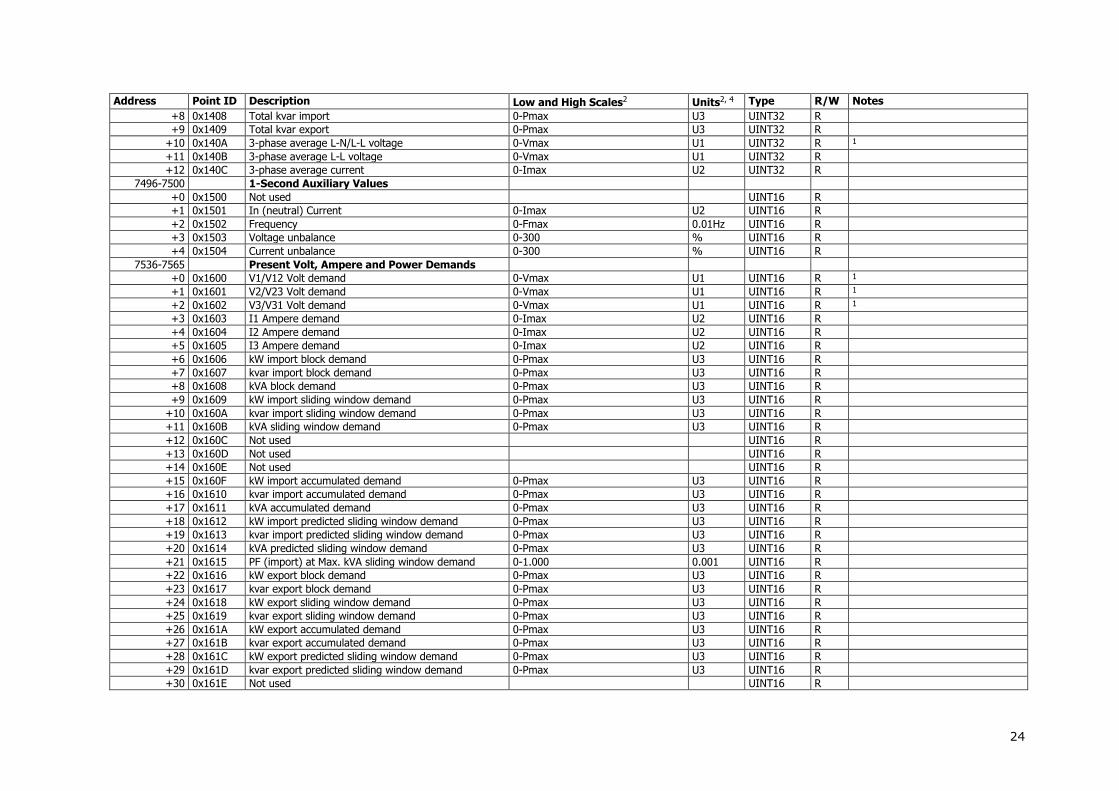
7496-7500 1-Second Auxiliary Values
+0 0x1500 Not used UINT16 R
+1 0x1501 In (neutral) Current 0-Imax U2 UINT16 R
+2 0x1502 Frequency 0-Fmax 0.01Hz UINT16 R
+3 0x1503 Voltage unbalance 0-300 % UINT16 R
+4 0x1504 Current unbalance 0-300 % UINT16 R
7536-7565 Present Volt, Ampere and Power Demands
+0 0x1600 V1/V12 Volt demand 0-Vmax U1 UINT16 R 1
+1 0x1601 V2/V23 Volt demand 0-Vmax U1 UINT16 R 1
+2 0x1602 V3/V31 Volt demand 0-Vmax U1 UINT16 R 1
+3 0x1603 I1 Ampere demand 0-Imax U2 UINT16 R
+4 0x1604 I2 Ampere demand 0-Imax U2 UINT16 R
+5 0x1605 I3 Ampere demand 0-Imax U2 UINT16 R
+6 0x1606 kW import block demand 0-Pmax U3 UINT16 R
+7 0x1607 kvar import block demand 0-Pmax U3 UINT16 R
+8 0x1608 kVA block demand 0-Pmax U3 UINT16 R
+9 0x1609 kW import sliding window demand 0-Pmax U3 UINT16 R
+10 0x160A kvar import sliding window demand 0-Pmax U3 UINT16 R
+11 0x160B kVA sliding window demand 0-Pmax U3 UINT16 R
+12 0x160C Not used UINT16 R
+13 0x160D Not used UINT16 R
+14 0x160E Not used UINT16 R
+15 0x160F kW import accumulated demand 0-Pmax U3 UINT16 R
+16 0x1610 kvar import accumulated demand 0-Pmax U3 UINT16 R
+17 0x1611 kVA accumulated demand 0-Pmax U3 UINT16 R
+18 0x1612 kW import predicted sliding window demand 0-Pmax U3 UINT16 R
+19 0x1613 kvar import predicted sliding window demand 0-Pmax U3 UINT16 R
+20 0x1614 kVA predicted sliding window demand 0-Pmax U3 UINT16 R
+21 0x1615 PF (import) at Max. kVA sliding window demand 0-1.000 0.001 UINT16 R
+22 0x1616 kW export block demand 0-Pmax U3 UINT16 R
+23 0x1617 kvar export block demand 0-Pmax U3 UINT16 R
+24 0x1618 kW export sliding window demand 0-Pmax U3 UINT16 R
+25 0x1619 kvar export sliding window demand 0-Pmax U3 UINT16 R
+26 0x161A kW export accumulated demand 0-Pmax U3 UINT16 R
+27 0x161B kvar export accumulated demand 0-Pmax U3 UINT16 R
+28 0x161C kW export predicted sliding window demand 0-Pmax U3 UINT16 R
+29 0x161D kvar export predicted sliding window demand 0-Pmax U3 UINT16 R
+30 0x161E Not used UINT16 R

25
Address Point ID Description Low and High Scales2 Units2, 4 Type R/W Notes
+31 0x161F Not used UINT16 R
+32 0x1620 Not used UINT16 R
+33 0x1621 Not used UINT16 R
+34 0x1622 In Ampere demand 0-Imax U2 UINT16 R
7576-7609 Total Energies E
+0,1 0x1700 kWh import 0-999,999,999 kWh UINT32 R
+2,3 0x1701 kWh export 0-999,999,999 kWh UINT32 R
+4,5 Not used INT32 R
+6,7 Not used UINT32 R
+8,9 0x1704 kvarh import 0-999,999,999 kvarh UINT32 R
+10,11 0x1705 kvarh export 0-999,999,999 kvarh UINT32 R
+12,13 Not used INT32 R
+14,15 Not used UINT32 R
+16,17 0x1708 kVAh total 0-999,999,999 kVAh UINT32 R
+18,19 0x1709 Not used UINT32 R
+20,21 0x170A Not used UINT32 R
+22,23 0x170B kVAh import 0-999,999,999 kVAh UINT32 R
+24,25 0x170C kVAh export 0-999,999,999 kVAh UINT32 R
+26,27 0x1712 kvarh Q1 0-999,999,999 kvarh UINT32 R
+28,29 0x1713 kvarh Q2 0-999,999,999 kvarh UINT32 R
+30,31 0x1714 kvarh Q3 0-999,999,999 kvarh UINT32 R
+32,33 0x1715 kvarh Q4 0-999,999,999 kvarh UINT32 R
7616-7633 Phase Energies E
+0,1 0x1800 kWh import L1 0-999,999,999 kWh UINT32 R
+2,3 0x1801 kWh import L2 0-999,999,999 kWh UINT32 R
+4,5 0x1802 kWh import L3 0-999,999,999 kWh UINT32 R
+6,7 0x1803 kvarh import L1 0-999,999,999 kvarh UINT32 R
+8,9 0x1804 kvarh import L2 0-999,999,999 kvarh UINT32 R
+10,11 0x1805 kvarh import L3 0-999,999,999 kvarh UINT32 R
+12,13 0x1806 kVAh total L1 0-999,999,999 kVAh UINT32 R
+14,15 0x1807 kVAh total L2 0-999,999,999 kVAh UINT32 R
+16,17 0x1808 kVAh total L3 0-999,999,999 kVAh UINT32 R
7656-7695 V1/V12 Harmonic Distortion EH 1
+0 0x1900 H01 Harmonic distortion 0-100.00 0.01% UINT16 R
+1 0x1901 H02 Harmonic distortion 0-100.00 0.01% UINT16 R
...
+39 0x1927 H40 Harmonic distortion 0-100.00 0.01% UINT16 R
7696-7735 V2/V23 Harmonic Distortion EH 1
+0 0x1A00 H01 Harmonic distortion 0-100.00 0.01% UINT16 R
+1 0x1A01 H02 Harmonic distortion 0-100.00 0.01% UINT16 R
...
+39 0x1A27 H40 Harmonic distortion 0-100.00 0.01% UINT16 R

26
Address Point ID Description Low and High Scales2 Units2, 4 Type R/W Notes
7736-7775 V3/V31 Harmonic Distortion EH 1
+0 0x1B00 H01 Harmonic distortion 0-100.00 0.01% UINT16 R
+1 0x1B01 H02 Harmonic distortion 0-100.00 0.01% UINT16 R
...
+39 0x1B27 H40 Harmonic distortion 0-100.00 0.01% UINT16 R
7776-7815 I1 Harmonic Distortion EH
+0 0x1C00 H01 Harmonic distortion 0-100.00 0.01% UINT16 R
+1 0x1C01 H02 Harmonic distortion 0-100.00 0.01% UINT16 R
...
+39 0x1C27 H40 Harmonic distortion 0-100.00 0.01% UINT16 R
7816-7855 I2 Harmonic Distortion EH
+0 0x1D00 H01 Harmonic distortion 0-100.00 0.01% UINT16 R
+1 0x1D01 H02 Harmonic distortion 0-100.00 0.01% UINT16 R
...
+39 0x1D27 H40 Harmonic distortion 0-100.00 0.01% UINT16 R
7856-7895 I3 Harmonic Distortion EH
+0 0x1E00 H01 Harmonic distortion 0-100.00 0.01% UINT16 R
+1 0x1E01 H02 Harmonic distortion 0-100.00 0.01% UINT16 R
...
+39 0x1E27 H40 Harmonic distortion 0-100.00 0.01% UINT16 R
8296-8313 Fundamental Phase Values EH 2-cycle values
+0 0x2900 V1/V12 Voltage 0-Vmax U1 UINT16 R 1
+1 0x2901 V2/V23 Voltage 0-Vmax U1 UINT16 R 1
+2 0x2902 V3/V31 Voltage 0-Vmax U1 UINT16 R 1
+3 0x2903 I1 Current 0-Imax U2 UINT16 R
+4 0x2904 I2 Current 0-Imax U2 UINT16 R
+5 0x2905 I3 Current 0-Imax U2 UINT16 R
+6 0x2906 kW L1 -Pmax-Pmax U3 INT16 R
+7 0x2907 kW L2 -Pmax-Pmax U3 INT16 R
+8 0x2908 kW L3 -Pmax-Pmax U3 INT16 R
+9 0x2909 kvar L1 -Pmax-Pmax U3 INT16 R
+10 0x290A kvar L2 -Pmax-Pmax U3 INT16 R
+11 0x290B kvar L3 -Pmax-Pmax U3 INT16 R
+12 0x290C kVA L1 0-Pmax U3 UINT16 R
+13 0x290D kVA L2 0-Pmax U3 UINT16 R
+14 0x290E kVA L3 0-Pmax U3 UINT16 R
+15 0x290F Power factor L1 -1.000-1.000 0.001 INT16 R
+16 0x2910 Power factor L2 -1.000-1.000 0.001 INT16 R
+17 0x2911 Power factor L3 -1.000-1.000 0.001 INT16 R
8336-8343 Fundamental Total Values EH 2-cycle values
+0 0x2A00 Total fundamental kW -Pmax-Pmax U3 INT16 R
+1 0x2A01 Total fundamental kvar -Pmax-Pmax U3 INT16 R
27
Address Point ID Description Low and High Scales2 Units2, 4 Type R/W Notes
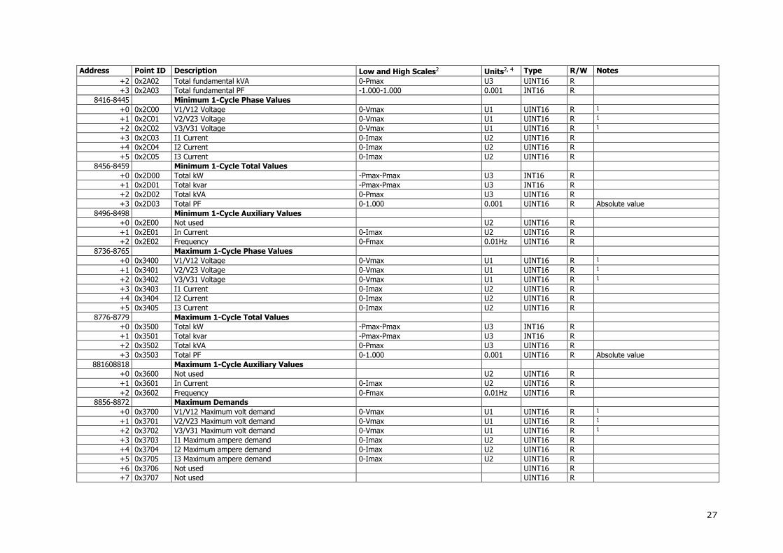
+2 0x2A02 Total fundamental kVA 0-Pmax U3 UINT16 R
+3 0x2A03 Total fundamental PF -1.000-1.000 0.001 INT16 R
8416-8445 Minimum 1-Cycle Phase Values
+0 0x2C00 V1/V12 Voltage 0-Vmax U1 UINT16 R 1
+1 0x2C01 V2/V23 Voltage 0-Vmax U1 UINT16 R 1
+2 0x2C02 V3/V31 Voltage 0-Vmax U1 UINT16 R 1
+3 0x2C03 I1 Current 0-Imax U2 UINT16 R
+4 0x2C04 I2 Current 0-Imax U2 UINT16 R
+5 0x2C05 I3 Current 0-Imax U2 UINT16 R
8456-8459 Minimum 1-Cycle Total Values
+0 0x2D00 Total kW -Pmax-Pmax U3 INT16 R
+1 0x2D01 Total kvar -Pmax-Pmax U3 INT16 R
+2 0x2D02 Total kVA 0-Pmax U3 UINT16 R
+3 0x2D03 Total PF 0-1.000 0.001 UINT16 R Absolute value
8496-8498 Minimum 1-Cycle Auxiliary Values
+0 0x2E00 Not used U2 UINT16 R
+1 0x2E01 In Current 0-Imax U2 UINT16 R
+2 0x2E02 Frequency 0-Fmax 0.01Hz UINT16 R
8736-8765 Maximum 1-Cycle Phase Values
+0 0x3400 V1/V12 Voltage 0-Vmax U1 UINT16 R 1
+1 0x3401 V2/V23 Voltage 0-Vmax U1 UINT16 R 1
+2 0x3402 V3/V31 Voltage 0-Vmax U1 UINT16 R 1
+3 0x3403 I1 Current 0-Imax U2 UINT16 R
+4 0x3404 I2 Current 0-Imax U2 UINT16 R
+5 0x3405 I3 Current 0-Imax U2 UINT16 R
8776-8779 Maximum 1-Cycle Total Values
+0 0x3500 Total kW -Pmax-Pmax U3 INT16 R
+1 0x3501 Total kvar -Pmax-Pmax U3 INT16 R
+2 0x3502 Total kVA 0-Pmax U3 UINT16 R
+3 0x3503 Total PF 0-1.000 0.001 UINT16 R Absolute value
881608818 Maximum 1-Cycle Auxiliary Values
+0 0x3600 Not used U2 UINT16 R
+1 0x3601 In Current 0-Imax U2 UINT16 R
+2 0x3602 Frequency 0-Fmax 0.01Hz UINT16 R
8856-8872 Maximum Demands
+0 0x3700 V1/V12 Maximum volt demand 0-Vmax U1 UINT16 R 1
+1 0x3701 V2/V23 Maximum volt demand 0-Vmax U1 UINT16 R 1
+2 0x3702 V3/V31 Maximum volt demand 0-Vmax U1 UINT16 R 1
+3 0x3703 I1 Maximum ampere demand 0-Imax U2 UINT16 R
+4 0x3704 I2 Maximum ampere demand 0-Imax U2 UINT16 R
+5 0x3705 I3 Maximum ampere demand 0-Imax U2 UINT16 R
+6 0x3706 Not used UINT16 R
+7 0x3707 Not used UINT16 R

28
Address Point ID Description Low and High Scales2 Units2, 4 Type R/W Notes
+8 0x3708 Not used UINT16 R
+9 0x3709 Maximum kW import sliding window demand 0-Pmax U3 UINT16 R
+10 0x370A Maximum kvar import sliding window demand 0-Pmax U3 UINT16 R
+11 0x370B Maximum kVA sliding window demand 0-Pmax U3 UINT16 R
+12 0x370C Not used UINT16 R
+13 0x370D Not used UINT16 R
+14 0x370E Not used UINT16 R
+15 0x370F Maximum kW export sliding window demand 0-Pmax U3 UINT16 R
+16 0x3710 Maximum kvar export sliding window demand 0-Pmax U3 UINT16 R
+17 0x3711 Not used UINT16 R
+18 0x3712 Not used UINT16 R
+19 0x3713 Not used UINT16 R
+20 0x3714 Not used UINT16 R
+21 0x3715 In Maximum ampere demand 0-Imax U2 UINT16 R
9056-9057 TOU Parameters E
+0 0x3C00 Active tariff 0-7 UINT16 R/W
+1 0x3C01 Active profile 0-15: 0-3 = Season 1 Profile #1-4, 4-7 = Season 2 Profile #1-4, 8-11 = Season 3 Profile #1-4, 12-15 = Season 4 Profile #1-4
UINT16 R/W
9076-9079 Scaled Analog Outputs
+0 0x3C80 Analog output AO1 0-4095 UINT16 R/W
+1 0x3C81 Analog output AO2 0-4095 UINT16 R/W
+2 0x3C82 Analog output AO3 0-4095 UINT16 R/W
+3 0x3C83 Analog output AO4 0-4095 UINT16 R/W
9096-9111 TOU Energy Register #1 E
+0,1 0x3D00 Tariff #1 register 0-999,999,999 kWh UINT32 R
+2,3 0x3D01 Tariff #2 register 0-999,999,999 kWh UINT32 R
… R
+14,15 0x3D07 Tariff #8 register 0-999,999,999 kWh UINT32 R
9136-9151 TOU Energy Register #2 E
+0,1 0x3E00 Tariff #1 register 0-999,999,999 kWh UINT32 R
+2,3 0x3E01 Tariff #2 register 0-999,999,999 kWh UINT32 R
… R
+14,15 0x3E07 Tariff #8 register 0-999,999,999 kWh UINT32 R
9176-9191 TOU Energy Register #3 E
+0,1 0x3F00 Tariff #1 register 0-999,999,999 kWh UINT32 R
+2,3 0x3F01 Tariff #2 register 0-999,999,999 kWh UINT32 R
… R
+14,15 0x3F07 Tariff #8 register 0-999,999,999 kWh UINT32 R
9216-9231 TOU Energy Register #4 E

29
Address Point ID Description Low and High Scales2 Units2, 4 Type R/W Notes
+0,1 0x4000 Tariff #1 register 0-999,999,999 kWh UINT32 R
+2,3 0x4001 Tariff #2 register 0-999,999,999 kWh UINT32 R
… R
+14,15 0x4007 Tariff #8 register 0-999,999,999 kWh UINT32 R
9416-9419 Summary Energy Accumulated Demands E
+0 0x4500 Summary register #1 demand 0-Pmax U3 UINT16 R
+1 0x4501 Summary register #2 demand 0-Pmax U3 UINT16 R
+2 0x4502 Summary register #3 demand 0-Pmax U3 UINT16 R
+3 0x4503 Summary register #4 demand 0-Pmax U3 UINT16 R
9436-9439 Summary Energy Block Demands E
+0 0x4580 Summary register #1 demand 0-Pmax U3 UINT16 R
+1 0x4581 Summary register #2 demand 0-Pmax U3 UINT16 R
+2 0x4582 Summary register #3 demand 0-Pmax U3 UINT16 R
+3 0x4583 Summary register #4 demand 0-Pmax U3 UINT16 R
9456-9459 Summary Energy Sliding Window Demands E
+0 0x4600 Summary register #1 demand 0-Pmax U3 UINT16 R
+1 0x4601 Summary register #2 demand 0-Pmax U3 UINT16 R
+2 0x4602 Summary register #3 demand 0-Pmax U3 UINT16 R
+3 0x4603 Summary register #4 demand 0-Pmax U3 UINT16 R
9516-9519 Summary Energy Maximum Demands E
+0 0x4780 Summary register #1 maximum demand 0-Pmax U3 UINT16 R
+1 0x4781 Summary register #2 maximum demand 0-Pmax U3 UINT16 R
+2 0x4782 Summary register #3 maximum demand 0-Pmax U3 UINT16 R
+3 0x4783 Summary register #4 maximum demand 0-Pmax U3 UINT16 R
9536-9543 TOU Maximum Demand Register #1 E
+0 0x4800 Tariff #1 maximum demand 0-Pmax U3 UINT16 R
+1 0x4801 Tariff #2 maximum demand 0-Pmax U3 UINT16 R
… R
+7 0x4807 Tariff #8 maximum demand 0-Pmax U3 UINT16 R
9576-9583 TOU Maximum Demand Register #2 E
+0 0x4900 Tariff #1 maximum demand 0-Pmax U3 UINT16 R
+1 0x4901 Tariff #2 maximum demand 0-Pmax U3 UINT16 R
… R
+7 0x4907 Tariff #8 maximum demand 0-Pmax U3 UINT16 R
9616-9623 TOU Maximum Demand Register #3 E
+0 0x4A00 Tariff #1 maximum demand 0-Pmax U3 UINT16 R
+1 0x4A01 Tariff #2 maximum demand 0-Pmax U3 UINT16 R
… R
+7 0x4A07 Tariff #8 maximum demand 0-Pmax U3 UINT16 R
9556-9563 TOU Maximum Demand Register #4 E

30
Address Point ID Description Low and High Scales2 Units2, 4 Type R/W Notes
+0 0x4880 Tariff #1 maximum demand 0-Pmax U3 UINT16 R
+1 0x4881 Tariff #2 maximum demand 0-Pmax U3 UINT16 R
… R
+7 0x4887 Tariff #8 maximum demand 0-Pmax U3 UINT16 R
10656-10695 V1/V12 Harmonic Angles EH 1, 3
+0 0x6400 H01 Harmonic angle -180.0-180.0 0.1º INT16 R
+1 0x6400 H02 Harmonic angle -180.0-180.0 0.1º INT16 R
...
+39 0x6427 H40 Harmonic angle -180.0-180.0 0.1º INT16 R
10696-10735 V2/V23 Harmonic Angles EH 1, 3
+0 0x6500 H01 Harmonic angle -180.0-180.0 0.1º INT16 R
+1 0x6500 H02 Harmonic angle -180.0-180.0 0.1º INT16 R
...
+39 0x6527 H40 Harmonic angle -180.0-180.0 0.1º INT16 R
10736-10775 V1/V31 Harmonic Angles EH 1, 3
+0 0x6600 H01 Harmonic angle -180.0-180.0 0.1º INT16 R
+1 0x6600 H02 Harmonic angle -180.0-180.0 0.1º INT16 R
...
+39 0x6627 H40 Harmonic angle -180.0-180.0 0.1º INT16 R
10816-10855 I1 Harmonic Angles EH 3
+0 0x6700 H01 Harmonic angle -180.0-180.0 0.1º INT16 R
+1 0x6700 H02 Harmonic angle -180.0-180.0 0.1º INT16 R
...
+39 0x6727 H40 Harmonic angle -180.0-180.0 0.1º INT16 R
10856-10895 I2 Harmonic Angles EH 3
+0 0x6800 H01 Harmonic angle -180.0-180.0 0.1º INT16 R
+1 0x6800 H02 Harmonic angle -180.0-180.0 0.1º INT16 R
...
+39 0x6827 H40 Harmonic angle -180.0-180.0 0.1º INT16 R
10896-10935 I3 Harmonic Angles EH 3
+0 0x6900 H01 Harmonic angle -180.0-180.0 0.1º INT16 R
+1 0x6900 H02 Harmonic angle -180.0-180.0 0.1º INT16 R
...
+39 0x6927 H40 Harmonic angle -180.0-180.0 0.1º INT16 R
11616 0x7C00 Setpoint Status 0x0000-0xFFFF UINT16 R Bitmap: 0=released, 1=operated
NOTES:
Energy and power demand readings are only available in PM130E and PM130EH meters. Harmonics are only available in PM130EH meters.
1 Voltage and voltage harmonics readings:
When the 4LN3, 3LN3 or 3BLN3 wiring mode is selected, the voltages will be line-to-neutral; for any other wiring mode, they will be line-to-line voltages.

31
2 For volts, amps, power and frequency scales and units refer to Section 4 ”Data Scales and Units”. For analog data scaling formulas and examples, see Section 2.7.1, “16-bit Scaled Integer Format”.
3 Harmonic angles are referenced to the fundamental voltage harmonic H01 on phase L1.
4 The binary counters and energy registers can be read either as 32-bit integer, or 32-bit floating-point values. Refer to Section 2.7 for details.

32
3.4 32-bit Analog Registers, Binary Registers and Counters
Address Point ID Description Options/Range2 Units2, 4 Type2 R/W Notes
11776-11777 0x0000 None 0 UINT32 R
Special Inputs
11904-11905 0x0101 Phase rotation order 0=error, 1=positive (ABC), 2=negative (CBA)
UINT32 R
12544-12545 0x0600 Digital Inputs 0x00000000-0x00000FFF UINT32 R Bitmap: 0=open, 1=closed
12800-12801 0x0800 Relay Outputs 0x00000000-0x0000000F UINT32 R Bitmap: 0=open, 1=closed
13056-13063 Counters
+0,1 0x0A00 Counter #1 0-99,999 UINT32 R/W
+2,3 0x0A01 Counter #2 0-99,999 UINT32 R/W
+4,5 0x0A02 Counter #3 0-99,999 UINT32 R/W
+6,7 0x0A03 Counter #4 0-99,999 UINT32 R/W
13312-13377 1-Cycle Phase Values
+0,1 0x0C00 V1/V12 Voltage 0-Vmax U1 UINT32 R 1
+2,3 0x0C01 V2/V23 Voltage 0-Vmax U1 UINT32 R 1
+4,5 0x0C02 V3/V31 Voltage 0-Vmax U1 UINT32 R 1
+6,7 0x0C03 I1 Current 0-Imax U2 UINT32 R
+8,9 0x0C04 I2 Current 0-Imax U2 UINT32 R
+10,11 0x0C05 I3 Current 0-Imax U2 UINT32 R
+12,13 0x0C06 kW L1 -Pmax-Pmax U3 INT32 R
+14,15 0x0C07 kW L2 -Pmax-Pmax U3 INT32 R
+16,17 0x0C08 kW L3 -Pmax-Pmax U3 INT32 R
+18,19 0x0C09 kvar L1 -Pmax-Pmax U3 INT32 R
+20,21 0x0C0A kvar L2 -Pmax-Pmax U3 INT32 R
+22,23 0x0C0B kvar L3 -Pmax-Pmax U3 INT32 R
+24,25 0x0C0C kVA L1 0-Pmax U3 UINT32 R
+26,27 0x0C0D kVA L2 0-Pmax U3 UINT32 R
+28,29 0x0C0E kVA L3 0-Pmax U3 UINT32 R
+30,31 0x0C0F Power factor L1 -1000-1000 0.001 INT32 R
+32,33 0x0C10 Power factor L2 -1000-1000 0.001 INT32 R
+34,35 0x0C11 Power factor L3 -1000-1000 0.001 INT32 R
+36,37 0x0C12 V1/V12 Voltage THD 0-9999 0.1% UINT32 R 1 2-cycle value
+38,39 0x0C13 V2/V23 Voltage THD 0-9999 0.1% UINT32 R 1 2-cycle value
+40,41 0x0C14 V3/V31 Voltage THD 0-9999 0.1% UINT32 R 1 2-cycle value
+42,43 0x0C15 I1 Current THD 0-9999 0.1% UINT32 R 2-cycle value
+44,45 0x0C16 I2 Current THD 0-9999 0.1% UINT32 R 2-cycle value
+46,47 0x0C17 I3 Current THD 0-9999 0.1% UINT32 R 2-cycle value
+48,49 0x0C18 I1 K-Factor 10-9999 0.1 UINT32 R 2-cycle value
+50,51 0x0C19 I2 K-Factor 10-9999 0.1 UINT32 R 2-cycle value
+52,53 0x0C1A I3 K-Factor 10-9999 0.1 UINT32 R 2-cycle value
+54,55 0x0C1B I1 Current TDD 0-1000 0.1% UINT32 R 2-cycle value

33
Address Point ID Description Options/Range2 Units2, 4 Type2 R/W Notes
+56,57 0x0C1C I2 Current TDD 0-1000 0.1% UINT32 R 2-cycle value
+58,59 0x0C1D I3 Current TDD 0-1000 0.1% UINT32 R 2-cycle value
+60,61 0x0C1E V12 Voltage 0-Vmax U1 UINT32 R
+62,63 0x0C1F V23 Voltage 0-Vmax U1 UINT32 R
+64,65 0x0C20 V31 Voltage 0-Vmax U1 UINT32 R
13696-13721 1-Cycle Total Values
+0,1 0x0F00 Total kW -Pmax-Pmax U3 INT32 R
+2,3 0x0F01 Total kvar -Pmax-Pmax U3 INT32 R
+4,5 0x0F02 Total kVA 0-Pmax U3 UINT32 R
+6,7 0x0F03 Total PF -1000-1000 0.001 INT32 R
+8,9 0x0F04 Total PF lag 0-1000 0.001 UINT16 R
+10,11 0x0F05 Total PF lead 0-1000 0.001 UINT16 R
+12,13 0x0F06 Total kW import 0-Pmax U3 UINT32 R
+14,15 0x0F07 Total kW export 0-Pmax U3 UINT32 R
+16,17 0x0F08 Total kvar import 0-Pmax U3 UINT32 R
+18,19 0x0F09 Total kvar export 0-Pmax U3 UINT32 R
+20,21 0x0F0A 3-phase average L-N/L-L voltage 0-Vmax U1 UINT32 R 1
+22,23 0x0F0B 3-phase average L-L voltage 0-Vmax U1 UINT32 R
+24,25 0x0F0C 3-phase average current 0-Imax U2 UINT32 R
13824-13833 1-Cycle Auxiliary Values
+0,1 0x1000 Not used UINT32 R
+2,3 0x1001 In (neutral) Current 0-Imax U2 UINT32 R
+4,5 0x1002 Frequency 0-Fmax 0.01Hz UINT32 R
+6,7 0x1003 Voltage unbalance 0-300 % UINT32 R
+8,9 0x1004 Current unbalance 0-300 % UINT32 R
13864-13895 Phasor
+0,1 0x1080 V1/V12 Voltage magnitude 0-Vmax U1 UINT32 R 1
+2,3 0x1081 V2/V23 Voltage magnitude 0-Vmax U1 UINT32 R 1
+4,5 0x1082 V3/V31 Voltage magnitude 0-Vmax U1 UINT32 R 1
+6,7 0x1083 Not used UINT32 R
+8,9 0x1084 I1 Current magnitude 0-Imax U2 UINT32 R
+10,11 0x1085 I2 Current magnitude 0-Imax U2 UINT32 R
+12,13 0x1086 I3 Current magnitude 0-Imax U2 UINT32 R
+14,15 0x1087 Not used UINT32 R
+16,17 0x1088 V1/V12 Voltage angle -1800-1800 0.1º INT32 R 1
+18,19 0x1089 V2/V23 Voltage angle -1800-1800 0.1º INT32 R 1
+20,21 0x108A V3/V31 Voltage angle -1800-1800 0.1º INT32 R 1
+22,23 0x108B Not used INT32 R
+24,25 0x108C I1 Current angle -1800-1800 0.1º INT32 R
+26,27 0x108D I2 Current angle -1800-1800 0.1º INT32 R
+28,29 0x108E I3 Current angle -1800-1800 0.1º INT32 R
+30,31 0x108F Not used INT32 R

34
Address Point ID Description Options/Range2 Units2, 4 Type2 R/W Notes
13952-14017 1-Second Phase Values
+0,1 0x1100 V1/V12 Voltage 0-Vmax U1 UINT32 R 1
+2,3 0x1101 V2/V23 Voltage 0-Vmax U1 UINT32 R 1
+4,5 0x1102 V3/V31 Voltage 0-Vmax U1 UINT32 R 1
+6,7 0x1103 I1 Current 0-Imax U2 UINT32 R
+8,9 0x1104 I2 Current 0-Imax U2 UINT32 R
+10,11 0x1105 I3 Current 0-Imax U2 UINT32 R
+12,13 0x1106 kW L1 -Pmax-Pmax U3 INT32 R
+14,15 0x1107 kW L2 -Pmax-Pmax U3 INT32 R
+16,17 0x1108 kW L3 -Pmax-Pmax U3 INT32 R
+18,19 0x1109 kvar L1 -Pmax-Pmax U3 INT32 R
+20,21 0x110A kvar L2 -Pmax-Pmax U3 INT32 R
+22,23 0x110B kvar L3 -Pmax-Pmax U3 INT32 R
+24,25 0x110C kVA L1 0-Pmax U3 UINT32 R
+26,27 0x110D kVA L2 0-Pmax U3 UINT32 R
+28,29 0x110E kVA L3 0-Pmax U3 UINT32 R
+30,31 0x110F Power factor L1 -1000-1000 0.001 INT32 R
+32,33 0x1110 Power factor L2 -1000-1000 0.001 INT32 R
+34,35 0x1111 Power factor L3 -1000-1000 0.001 INT32 R
+36,37 0x1112 V1/V12 Voltage THD 0-9999 0.1% UINT32 R 1 3-sec value
+38,39 0x1113 V2/V23 Voltage THD 0-9999 0.1% UINT32 R 1 3-sec value
+40,41 0x1114 V3/V31 Voltage THD 0-9999 0.1% UINT32 R 1 3-sec value
+42,43 0x1115 I1 Current THD 0-9999 0.1% UINT32 R 3-sec value
+44,45 0x1116 I2 Current THD 0-9999 0.1% UINT32 R 3-sec value
+46,47 0x1117 I3 Current THD 0-9999 0.1% UINT32 R 3-sec value
+48,49 0x1118 I1 K-Factor 10-9999 0.1 UINT32 R 3-sec value
+50,51 0x1119 I2 K-Factor 10-9999 0.1 UINT32 R 3-sec value
+52,53 0x111A I3 K-Factor 10-9999 0.1 UINT32 R 3-sec value
+54,55 0x111B I1 Current TDD 0-1000 0.1% UINT32 R 3-sec value
+56,57 0x111C I2 Current TDD 0-1000 0.1% UINT32 R 3-sec value
+58,59 0x111D I3 Current TDD 0-1000 0.1% UINT32 R 3-sec value
+60,61 0x111E V12 Voltage 0-Vmax U1 UINT32 R
+62,63 0x111F V23 Voltage 0-Vmax U1 UINT32 R
+64,65 0x1120 V31 Voltage 0-Vmax U1 UINT32 R
14336-14361 1-Second Total Values
+0,1 0x1400 Total kW -Pmax-Pmax U3 INT32 R
+2,3 0x1401 Total kvar -Pmax-Pmax U3 INT32 R
+4,5 0x1402 Total kVA 0-Pmax U3 UINT32 R
+6,7 0x1403 Total PF -1000-1000 0.001 INT32 R
+8,9 0x1404 Total PF lag 0-1000 0.001 UINT16 R
+10,11 0x1405 Total PF lead 0-1000 0.001 UINT16 R
+12,13 0x1406 Total kW import 0-Pmax U3 UINT32 R
+14,15 0x1407 Total kW export 0-Pmax U3 UINT32 R

35
Address Point ID Description Options/Range2 Units2, 4 Type2 R/W Notes
+16,17 0x1408 Total kvar import 0-Pmax U3 UINT32 R
+18,19 0x1409 Total kvar export 0-Pmax U3 UINT32 R
+20,21 0x140A 3-phase average L-N/L-L voltage 0-Vmax U1 UINT32 R 1
+22,23 0x140B 3-phase average L-L voltage 0-Vmax U1 UINT32 R
+24,25 0x140C 3-phase average current 0-Imax U2 UINT32 R
14464-14473 1-Second Auxiliary Values
+0,1 0x1500 Not used UINT32 R
+2,3 0x1501 In (neutral) Current 0-Imax U2 UINT32 R
+4,5 0x1502 Frequency 0-Fmax 0.01Hz UINT32 R
+6,7 0x1503 Voltage unbalance 0-300 % UINT32 R
+8,9 0x1504 Current unbalance 0-300 % UINT32 R
14592-14651 Present Volt, Ampere and Power Demands
+0,1 0x1600 V1/V12 Volt demand 0-Vmax U1 UINT32 R 1
+2,3 0x1601 V2/V23 Volt demand 0-Vmax U1 UINT32 R 1
+4,5 0x1602 V3/V31 Volt demand 0-Vmax U1 UINT32 R 1
+6,7 0x1603 I1 Ampere demand 0-Imax U2 UINT32 R
+8,9 0x1604 I2 Ampere demand 0-Imax U2 UINT32 R
+10,11 0x1605 I3 Ampere demand 0-Imax U2 UINT32 R
+12,13 0x1606 kW import block demand 0-Pmax U3 UINT32 R
+14,15 0x1607 kvar import block demand 0-Pmax U3 UINT32 R
+16,17 0x1608 kVA block demand 0-Pmax U3 UINT32 R
+18,19 0x1609 kW import sliding window demand 0-Pmax U3 UINT32 R
+20,21 0x160A kvar import sliding window demand 0-Pmax U3 UINT32 R
+22,23 0x160B kVA sliding window demand 0-Pmax U3 UINT32 R
+24,25 0x160C Not used UINT32 R
+26,27 0x160D Not used UINT32 R
+28,29 0x160E Not used UINT32 R
+30,31 0x160F kW import accumulated demand 0-Pmax U3 UINT32 R
+32,33 0x1610 kvar import accumulated demand 0-Pmax U3 UINT32 R
+34,35 0x1611 kVA accumulated demand 0-Pmax U3 UINT32 R
+36,37 0x1612 kW import predicted sliding window demand 0-Pmax U3 UINT32 R
+38,39 0x1613 kvar import predicted sliding window demand 0-Pmax U3 UINT32 R
+40,41 0x1614 kVA predicted sliding window demand 0-Pmax U3 UINT32 R
+42,43 0x1615 PF (import) at Max. kVA sliding window demand 0-1000 0.001 UINT32 R
+44,45 0x1616 kW export block demand 0-Pmax U3 UINT32 R
+46,47 0x1617 kvar export block demand 0-Pmax U3 UINT32 R
+48,49 0x1618 kW export sliding window demand 0-Pmax U3 UINT32 R
+50,51 0x1619 kvar export sliding window demand 0-Pmax U3 UINT32 R
+52,53 0x161A kW export accumulated demand 0-Pmax U3 UINT32 R
+54,55 0x161B kvar export accumulated demand 0-Pmax U3 UINT32 R
+56,57 0x161C kW export predicted sliding window demand 0-Pmax U3 UINT32 R
+58,59 0x161D kvar export predicted sliding window demand 0-Pmax U3 UINT32 R
+60,61 0x161E Not used UINT32 R

36
Address Point ID Description Options/Range2 Units2, 4 Type2 R/W Notes
+62,63 0x161F Not used UINT32 R
+64,65 0x1620 Not used UINT32 R
+66,67 0x1621 Not used UINT32 R
+68,69 0x1622 In Ampere demand 0-Imax U2 UINT32 R
14720-14753 Total Energies E
+0,1 0x1700 kWh import 0-999,999,999 kWh UINT32 R
+2,3 0x1701 kWh export 0-999,999,999 kWh UINT32 R
+4,5 0x1702 Not used INT32 R
+6,7 0x1703 Not used UINT32 R
+8,9 0x1704 kvarh import 0-999,999,999 kvarh UINT32 R
+10,11 0x1705 kvarh export 0-999,999,999 kvarh UINT32 R
+12,13 0x1706 Not used INT32 R
+14,15 0x1707 Not used UINT32 R
+16,17 0x1708 kVAh total 0-999,999,999 kVAh UINT32 R
+18,19 0x1709 Not used UINT32 R
+20,21 0x170A Not used UINT32 R
+22,23 0x170B kVAh import 0-999,999,999 kVAh UINT32 R
+24,25 0x170C kVAh export 0-999,999,999 kVAh UINT32 R
+26,27 0x1712 kvarh Q1 0-999,999,999 kvarh UINT32 R
+28,29 0x1713 kvarh Q2 0-999,999,999 kvarh UINT32 R
+30,31 0x1714 kvarh Q3 0-999,999,999 kvarh UINT32 R
+32,33 0x1715 kvarh Q4 0-999,999,999 kvarh UINT32 R
14760-14767 Summary Energy Registers E
+0,1 0x1780 Summary energy register #1 0-999,999,999 kWh UINT32 R
+2,3 0x1781 Summary energy register #2 0-999,999,999 kWh UINT32 R
+4,5 0x1782 Summary energy register #3 0-999,999,999 kWh UINT32 R
+6,7 0x1783 Summary energy register #4 0-999,999,999 kWh UINT32 R
14848-14865 Phase Energies E
+0,1 0x1800 kWh import L1 0-999,999,999 kWh UINT32 R
+2,3 0x1801 kWh import L2 0-999,999,999 kWh UINT32 R
+4,5 0x1802 kWh import L3 0-999,999,999 kWh UINT32 R
+6,7 0x1803 kvarh import L1 0-999,999,999 kvarh UINT32 R
+8,9 0x1804 kvarh import L2 0-999,999,999 kvarh UINT32 R
+10,11 0x1805 kvarh import L3 0-999,999,999 kvarh UINT32 R
+12,13 0x1806 kVAh total L1 0-999,999,999 kVAh UINT32 R
+14,15 0x1807 kVAh total L2 0-999,999,999 kVAh UINT32 R
+16,17 0x1808 kVAh total L3 0-999,999,999 kVAh UINT32 R
14976-15055 V1/V12 Harmonic Distortions EH 1
+0,1 0x1900 H01 Harmonic distortion 0-10000 0.01% UINT32 R
+2,3 0x1901 H02 Harmonic distortion 0-10000 0.01% UINT32 R
...
+78,79 0x1927 H40 Harmonic distortion 0-10000 0.01% UINT32 R

37
Address Point ID Description Options/Range2 Units2, 4 Type2 R/W Notes
15104-15183 V2/V23 Harmonic Distortions EH 1
+0,1 0x1A00 H01 Harmonic distortion 0-10000 0.01% UINT32 R
+2,3 0x1A01 H02 Harmonic distortion 0-10000 0.01% UINT32 R
...
+78,79 0x1A27 H40 Harmonic distortion 0-10000 0.01% UINT32 R
15232-15311 V3/V31 Harmonic Distortions EH 1
+0,1 0x1B00 H01 Harmonic distortion 0-10000 0.01% UINT32 R
+2,3 0x1B01 H02 Harmonic distortion 0-10000 0.01% UINT32 R
...
+78,79 0x1B27 H40 Harmonic distortion 0-10000 0.01% UINT32 R
15360-15439 I1 Harmonic Distortions EH
+0,1 0x1C00 H01 Harmonic distortion 0-10000 0.01% UINT32 R
+2,3 0x1C01 H02 Harmonic distortion 0-10000 0.01% UINT32 R
...
+78,79 0x1C27 H40 Harmonic distortion 0-10000 0.01% UINT32 R
15488-15567 I2 Harmonic Distortions EH
+0,1 0x1D00 H01 Harmonic distortion 0-10000 0.01% UINT32 R
+2,3 0x1D01 H02 Harmonic distortion 0-10000 0.01% UINT32 R
...
+78,79 0x1D27 H40 Harmonic distortion 0-10000 0.01% UINT32 R
15616-15695 I3 Harmonic Distortions EH
+0,1 0x1E00 H01 Harmonic distortion 0-10000 0.01% UINT32 R
+2,3 0x1E01 H02 Harmonic distortion 0-10000 0.01% UINT32 R
...
+78,79 0x1E27 H40 Harmonic distortion 0-10000 0.01% UINT32 R
17024-17059 Fundamental (H01) Phase Values EH 2-cycle values
+0,1 0x2900 V1/V12 Voltage 0-Vmax U1 UINT32 R 1
+2,3 0x2901 V2/V23 Voltage 0-Vmax U1 UINT32 R 1
+4,5 0x2902 V3/V31 Voltage 0-Vmax U1 UINT32 R 1
+6,7 0x2903 I1 Current 0-Imax U2 UINT32 R
+8,9 0x2904 I2 Current 0-Imax U2 UINT32 R
+10,11 0x2905 I3 Current 0-Imax U2 UINT32 R
+12,13 0x2906 kW L1 -Pmax-Pmax U3 INT32 R
+14,15 0x2907 kW L2 -Pmax-Pmax U3 INT32 R
+16,17 0x2908 kW L3 -Pmax-Pmax U3 INT32 R
+18,19 0x2909 kvar L1 -Pmax-Pmax U3 INT32 R
+20,21 0x290A kvar L2 -Pmax-Pmax U3 INT32 R
+22,23 0x290B kvar L3 -Pmax-Pmax U3 INT32 R
+24,25 0x290C kVA L1 0-Pmax U3 UINT32 R
+26,27 0x290D kVA L2 0-Pmax U3 UINT32 R
+28,29 0x290E kVA L3 0-Pmax U3 UINT32 R
+30,31 0x290F Power factor L1 -1000-1000 0.001 INT32 R

38
Address Point ID Description Options/Range2 Units2, 4 Type2 R/W Notes
+32,33 0x2910 Power factor L2 -1000-1000 0.001 INT32 R
+34,35 0x2911 Power factor L3 -1000-1000 0.001 INT32 R
17152-17164 Harmonic Total Values EH 2-cycle values
+0,1 0x2A00 Total fundamental kW -Pmax-Pmax U3 INT32 R
+2,3 0x2A01 Total fundamental kvar -Pmax-Pmax U3 INT32 R
+4,5 0x2A02 Total fundamental kVA 0-Pmax U3 UINT32 R
+6,7 0x2A03 Total fundamental PF -1000-1000 0.001 INT32 R
17408-17467 Minimum 1-Cycle Phase Values
+0,1 0x2C00 V1/V12 Voltage 0-Vmax U1 UINT32 R 1
+2,3 0x2C01 V2/V23 Voltage 0-Vmax U1 UINT32 R 1
+4,5 0x2C02 V3/V31 Voltage 0-Vmax U1 UINT32 R 1
+6,7 0x2C03 I1 Current 0-Imax U2 UINT32 R
+8,9 0x2C04 I2 Current 0-Imax U2 UINT32 R
+10,11 0x2C05 I3 Current 0-Imax U2 UINT32 R
17536-17543 Minimum 1-Cycle Total Values
+0,1 0x2D00 Total kW -Pmax-Pmax U3 INT32 R
+2,3 0x2D01 Total kvar -Pmax-Pmax U3 INT32 R
+4,5 0x2D02 Total kVA 0-Pmax U3 UINT32 R
+6,7 0x2D03 Total PF 0-1000 0.001 UINT32 R Absolute value
17664-17669 Minimum 1-Cycle Auxiliary Values
+0,1 0x2E00 Not used UINT32 R
+2,3 0x2E01 In Current 0-Imax U2 UINT32 R
+4,5 0x2E02 Frequency 0-Fmax 0.01Hz UINT32 R
18432-18491 Maximum 1-Cycle Phase Values
+0,1 0x3400 V1/V12 Voltage 0-Vmax U1 UINT32 R 1
+2,3 0x3401 V2/V23 Voltage 0-Vmax U1 UINT32 R 1
+4,5 0x3402 V3/V31 Voltage 0-Vmax U1 UINT32 R 1
+6,7 0x3403 I1 Current 0-Imax U2 UINT32 R
+8,9 0x3404 I2 Current 0-Imax U2 UINT32 R
+10,11 0x3405 I3 Current 0-Imax U2 UINT32 R
18560-18567 Maximum 1-Cycle Total Values
+0,1 0x3500 Total kW -Pmax-Pmax U3 INT32 R
+2,3 0x3501 Total kvar -Pmax-Pmax U3 INT32 R
+4,5 0x3502 Total kVA 0-Pmax U3 UINT32 R
+6,7 0x3503 Total PF 0-1000 0.001 UINT32 R Absolute value
18688-18693 Maximum 1-Cycle Auxiliary Values
+0,1 0x3600 Not used UINT32 R
+2,3 0x3601 In Current 0-Imax U2 UINT32 R
+4,5 0x3602 Frequency 0-Fmax 0.01Hz UINT32 R
18816-18849 Maximum Demands
+0,1 0x3700 V1/V12 Maximum volt demand 0-Vmax U1 UINT32 R 1
+2,3 0x3701 V2/V23 Maximum volt demand 0-Vmax U1 UINT32 R 1
+4,5 0x3702 V3/V31 Maximum volt demand 0-Vmax U1 UINT32 R 1

39
Address Point ID Description Options/Range2 Units2, 4 Type2 R/W Notes
+6,7 0x3703 I1 Maximum ampere demand 0-Imax U2 UINT32 R
+8,9 0x3704 I2 Maximum ampere demand 0-Imax U2 UINT32 R
+10,11 0x3705 I3 Maximum ampere demand 0-Imax U2 UINT32 R
+12,13 0x3706 Not used UINT32 R
+14,15 0x3707 Not used UINT32 R
+16,17 0x3708 Not used UINT32 R
+18,19 0x3709 Maximum kW import sliding window demand 0-Pmax U3 UINT32 R
+20,21 0x370A Maximum kvar import sliding window demand 0-Pmax U3 UINT32 R
+22,23 0x370B Maximum kVA sliding window demand 0-Pmax U3 UINT32 R
+24,25 0x3737 Not used UINT32 R
+26,27 0x370D Not used UINT32 R
+28,29 0x370E Not used UINT32 R
+30,31 0x370F Maximum kW export sliding window demand 0-Pmax U3 UINT32 R
+32,33 0x3710 Maximum kvar export sliding window demand 0-Pmax U3 UINT32 R
+34,35 0x3711 Not used UINT32 R
+36,37 0x3712 Not used UINT32 R
+38,39 0x3713 Not used UINT32 R
+40,41 0x3714 Not used UINT32 R
+42,43 0x3715 In Maximum ampere demand 0-Imax U2 UINT32 R
19456-19459 TOU Parameters E
+0,1 0x3C00 Active tariff 0-7 UINT32 R
+2,3 0x3C01 Active profile 0-15: 1-3 = Season 1 Profile #1-4, 4-7 = Season 2 Profile #1-4, 8-11 = Season 3 Profile #1-4, 12-15 = Season 4 Profile #1-4
UINT32 R
19496-19503 Scaled Analog Outputs
+0,1 0x3C80 Analog output AO1 0-4095 UINT32 R/W
+2,3 0x3C81 Analog output AO2 0-4095 UINT32 R/W
+4,5 0x3C82 Analog output AO3 0-4095 UINT32 R/W
+6,7 0x3C83 Analog output AO4 0-4095 UINT32 R/W
19584-19599 TOU Energy Register #1 E
+0,1 0x3D00 Tariff #1 register 0-999,999,999 kWh UINT32 R
+2,3 0x3D01 Tariff #2 register 0-999,999,999 kWh UINT32 R
… R
+14,15 0x3D07 Tariff #8 register 0-999,999,999 kWh UINT32 R
19712-19727 TOU Energy Register #2 E
+0,1 0x3E00 Tariff #1 register 0-999,999,999 kWh UINT32 R
+2,3 0x3E01 Tariff #2 register 0-999,999,999 kWh UINT32 R
… R
+14,15 0x3E07 Tariff #8 register 0-999,999,999 kWh UINT32 R
19840-19855 TOU Energy Register #3 E
+0,1 0x3F00 Tariff #1 register 0-999,999,999 kWh UINT32 R

40
Address Point ID Description Options/Range2 Units2, 4 Type2 R/W Notes
+2,3 0x3F01 Tariff #2 register 0-999,999,999 kWh UINT32 R
… R
+14,15 0x3F07 Tariff #8 register 0-999,999,999 kWh UINT32 R
19968-19983 TOU Energy Register #4 E
+0,1 0x4000 Tariff #1 register 0-999,999,999 kWh UINT32 R
+2,3 0x4001 Tariff #2 register 0-999,999,999 kWh UINT32 R
… R
+14,15 0x4007 Tariff #8 register 0-999,999,999 kWh UINT32 R
20608-20615 Summary Energy Accumulated Demands E
+0,1 0x4500 Summary register #1 demand 0-Pmax U3 UINT32 R
+2,3 0x4501 Summary register #2 demand 0-Pmax U3 UINT32 R
+4,5 0x4502 Summary register #3 demand 0-Pmax U3 UINT32 R
+6,7 0x4503 Summary register #4 demand 0-Pmax U3 UINT32 R
20648-20655 Summary Energy Block Demands E
+0,1 0x4580 Summary register #1 demand 0-Pmax U3 UINT32 R
+2,3 0x4581 Summary register #2 demand 0-Pmax U3 UINT32 R
+4,5 0x4582 Summary register #3 demand 0-Pmax U3 UINT32 R
+6,7 0x4583 Summary register #4 demand 0-Pmax U3 UINT32 R
20736-20743 Summary Energy Sliding Window Demands E
+0,1 0x4600 Summary register #1 demand 0-Pmax U3 UINT32 R
+2,3 0x4601 Summary register #2 demand 0-Pmax U3 UINT32 R
+4,5 0x4602 Summary register #3 demand 0-Pmax U3 UINT32 R
+6,7 0x4603 Summary register #4 demand 0-Pmax U3 UINT32 R
20904-20911 Summary Energy Maximum Demands E
+0,1 0x4780 Summary register #1 maximum demand 0-Pmax U3 UINT32 R
+2,3 0x4781 Summary register #2 maximum demand 0-Pmax U3 UINT32 R
+4,5 0x4782 Summary register #3 maximum demand 0-Pmax U3 UINT32 R
+6,7 0x4783 Summary register #4 maximum demand 0-Pmax U3 UINT32 R
20992-21023 TOU Maximum Demand Register #1 E
+0,1 0x4800 Tariff #1 maximum demand 0-Pmax U3 UINT32 R
+2,3 0x4801 Tariff #2 maximum demand 0-Pmax U3 UINT32 R
… R
+14,15 0x4807 Tariff #8 maximum demand 0-Pmax U3 UINT32 R
21120-21135 TOU Maximum Demand Register #2 E
+0,1 0x4900 Tariff #1 maximum demand 0-Pmax U3 UINT32 R
+2,3 0x4901 Tariff #2 maximum demand 0-Pmax U3 UINT32 R
… R
+14,15 0x4907 Tariff #8 maximum demand 0-Pmax U3 UINT32 R
21248-21263 TOU Maximum Demand Register #3 E
+0,1 0x4A00 Tariff #1 maximum demand 0-Pmax U3 UINT32 R

41
Address Point ID Description Options/Range2 Units2, 4 Type2 R/W Notes
+2,3 0x4A01 Tariff #2 maximum demand 0-Pmax U3 UINT32 R
… R
+14,15 0x4A07 Tariff #8 maximum demand 0-Pmax U3 UINT32 R
21032-21047 TOU Maximum Demand Register #4 E
+0,1 0x4880 Tariff #1 maximum demand 0-Pmax U3 UINT32 R
+2,3 0x4881 Tariff #2 maximum demand 0-Pmax U3 UINT32 R
… R
+14,15 0x4887 Tariff #8 maximum demand 0-Pmax U3 UINT32 R
24576-24655 V1/V12 Harmonic Angles EH 1, 3
+0,1 0x6400 H01 Harmonic angle -1800-1800 0.1º INT32 R
+2,3 0x6400 H02 Harmonic angle -1800-1800 0.1º INT32 R
...
+78,79 0x6427 H40 Harmonic angle -1800-1800 0.1º INT32 R
24704-24783 V2/V23 Harmonic Angles EH 1, 3
+0,1 0x6500 H01 Harmonic angle -1800-1800 0.1º INT32 R
+2,3 0x6500 H02 Harmonic angle -1800-1800 0.1º INT32 R
...
+78,79 0x6527 H40 Harmonic angle -1800-1800 0.1º INT32 R
24832-24911 V1/V31 Harmonic Angles EH 1, 3
+0,1 0x6600 H01 Harmonic angle -1800-1800 0.1º INT32 R
+2,3 0x6600 H02 Harmonic angle -1800-1800 0.1º INT32 R
...
+78,79 0x6627 H40 Harmonic angle -1800-1800 0.1º INT32 R
25088-25167 I1 Harmonic Angles EH 3
+0,1 0x6700 H01 Harmonic angle -1800-1800 0.1º INT32 R
+2,3 0x6700 H02 Harmonic angle -1800-1800 0.1º INT32 R
...
+78,79 0x6727 H40 Harmonic angle -1800-1800 0.1º INT32 R
25216-25295 I2 Harmonic Angles EH 3
+0,1 0x6800 H01 Harmonic angle -1800-1800 0.1º INT32 R
+2,3 0x6800 H02 Harmonic angle -1800-1800 0.1º INT32 R
...
+78,79 0x6827 H40 Harmonic angle -1800-1800 0.1º INT32 R
25344-25423 I3 Harmonic Angles EH 3
+0,1 0x6900 H01 Harmonic angle -1800-1800 0.1º INT32 R
+2,3 0x6900 H02 Harmonic angle -1800-1800 0.1º INT32 R
...
+78,79 0x6927 H40 Harmonic angle -1800-1800 0.1º INT32 R
27648-27649 0x7C00 Setpoint Status 0x00000000-0x0000FFFF UINT32 R Bitmap: 0=released, 1=operated
Generic TOU Season Energy Registers Point references
0x7000 Tariff #1 register 0-999,999,999 kWh UINT32

42
Address Point ID Description Options/Range2 Units2, 4 Type2 R/W Notes
0x7001 Tariff #2 register 0-999,999,999 kWh UINT32
…
0x7007 Tariff #8 register 0-999,999,999 kWh UINT32
Generic TOU Season Maximum Demand Registers
Point references
0x7100 Tariff #1 register 0-Pmax U3 UINT32
0x7101 Tariff #2 register 0-Pmax U3 UINT32
…
0x7107 Tariff #8 register 0-Pmax U3 UINT32
Generic Data Point references
0x7400 V1 voltage 0-Vmax U1 UINT32
0x7401 V2 voltage 0-Vmax U1 UINT32
0x7402 V3 voltage 0-Vmax U1 UINT32
0x7404 V12 voltage 0-Vmax U1 UINT32
0x7405 V23 voltage 0-Vmax U1 UINT32
0x7406 V31 voltage 0-Vmax U1 UINT32
0x7407 I1 current 0-Imax U2 UINT32
0x7408 I2 current 0-Imax U2 UINT32
0x7409 I3 current 0-Imax U2 UINT32
NOTES:
Energy and power demand readings are only available in PM130E and PM130EH meters. Harmonics are only available in PM130EH meters.
1 Voltage and voltage harmonics readings:
When the 4LN3, 3LN3 or 3BLN3 wiring mode is selected, the voltages will be line-to-neutral; for any other wiring mode, they will be line-to-line voltages.
2 For volts, amps, power and frequency scales and units, refer to Section 4 ”Data Scales and Units”.
3 Harmonic angles are referenced to the fundamental voltage harmonic H01 on phase L1.
4 The registers can be read as 32-bit integer or 32-bit floating-point values. Refer to Section 2.7 for details.

43
3.5 Minimum/Maximum Log Registers
Address Point ID Description Options/Range/Format2 Units2, 3 Type R/W Notes
35840-35959 Minimum Phase Values
+0,1 +2,3
0x2C00 Min. V1/V12 Voltage Timestamp
0-Vmax F1
U1 sec
UINT32 UINT32
R R
1
+4,5 +6,7
0x2C01 Min. V2/V23 Voltage Timestamp
0-Vmax F1
U1 sec
UINT32 UINT32
R R
1
+8,9 +10,11
0x2C02 Min. V3/V31 Voltage Timestamp
0-Vmax F1
U1 sec
UINT32 UINT32
R R
1
+12,13 +14,15
0x2C03 Min. I1 Current Timestamp
0-Imax F1
U2 sec
UINT32 UINT32
R R
+16,17 +18,19
0x2C04 Min. I2 Current Timestamp
0-Imax U2 sec
UINT32 UINT32
R R
+20,21 +22,23
0x2C05 Min. I3 Current Timestamp
0-Imax U2 sec
UINT32 UINT32
R R
36096-36111 Minimum Total Values
+0,1 +2,3
0x2D00 Min. Total kW Timestamp
-Pmax-Pmax U3 sec
INT32 UINT32
R R
+4,5 +6,7
0x2D01 Min. Total kvar Timestamp
-Pmax-Pmax U3 sec
INT32 UINT32
R R
+8,9 +10,11
0x2D02 Min. Total kVA Timestamp
0-Pmax U3 sec
UINT32 UINT32
R R
+12,13 +14,15
0x2D03 Min. Total PF Timestamp
-1000-1000 0.001
sec
INT32 UINT32
R R
36352-36362 Minimum Auxiliary Values
+0,1 +2,3
0x2E00 Not used UINT32 UINT32
R R
+4,5 +6,7
0x2E01 Min. In Current Timestamp
0-Imax U2 sec
UINT32 UINT32
R R
+8,9 +10,11
0x2E02 Min. Frequency Timestamp
0-Fmax 0.01Hz
sec
UINT32 UINT32
R R
36864-36983 Maximum Phase Values
+0,1 +2,3
0x3400 Max. V1/V12 Voltage Timestamp
0-Vmax
U1 sec
UINT32 UINT32
R R
1
+4,5 +6,7
0x3401 Max. V2/V23 Voltage Timestamp
0-Vmax U1 sec
UINT32 UINT32
R R
1
+8,9 +10,11
0x3402 Max. V3/V31 Voltage Timestamp
0-Vmax U1 sec
UINT32 UINT32
R R
1
+12,13 +14,15
0x3403 Max. I1 Current Timestamp
0-Imax U2 sec
UINT32 UINT32
R R
+16,17 +18,19
0x3404 Max. I2 Current Timestamp
0-Imax U2 sec
UINT32 UINT32
R R
+20,21 0x3405 Max. I3 Current 0-Imax U2 UINT32 R

44
Address Point ID Description Options/Range/Format2 Units2, 3 Type R/W Notes
+22,23 Timestamp sec UINT32 R
37120-37135 Maximum Total Values
+0,1 +2,3
0x3500 Max. Total kW Timestamp
-Pmax-Pmax U3 sec
INT32 UINT32
R R
+4,5 +6,7
0x3501 Max. Total kvar Timestamp
-Pmax-Pmax U3 sec
INT32 UINT32
R R
+8,9 +10,11
0x3502 Max. Total kVA Timestamp
0-Pmax U3 sec
UINT32 UINT32
R R
+12,13 +14,15
0x3503 Max. Total PF Timestamp
-1000-1000 0.001
sec
INT32 UINT32
R R
37376-37387 Maximum Auxiliary Values
+0,1 +2,3
0x3600 Not used UINT32 UINT32
R R
+4,5 +6,7
0x3601 Max. In Current Timestamp
0-Imax U2 sec
UINT32 UINT32
R R
+8,9 +10,11
0x3602 Max. Frequency Timestamp
0-Fmax 0.01Hz
sec
UINT32 UINT32
R R
37504-37535 Summary Energy Maximum Demands E
+0,1 +2,3
0x4780 Summary register #1 Maximum Demand
Timestamp
0-Pmax U3 UINT32 R
+4,5 +6,7
0x4781 Summary register #2 Maximum Demand
Timestamp
0-Pmax U3 UINT32 R
…
+12,13 +14,15
0x4783 Summary register #4 Maximum Demand
Timestamp
0-Pmax U3 UINT32 R
37632-37695 Maximum Demands
+0,1 +2,3
0x3700 V1/V12 Maximum volt demand Timestamp
0-Vmax U1 sec
UINT32 UINT32
R R
1
+4,5 +6,7
0x3701 V2/V23 Maximum volt demand Timestamp
0-Vmax U1 sec
UINT32 UINT32
R R
1
+8,9 +10,11
0x3702 V3/V31 Maximum volt demand Timestamp
0-Vmax U1 sec
UINT32 UINT32
R R
1
+12,13 +14,15
0x3703 I1 Maximum ampere demand Timestamp
0-Imax U2 sec
UINT32 UINT32
R R
+16,17 +18,19
0x3704 I2 Maximum ampere demand Timestamp
0-Imax U2 sec
UINT32 UINT32
R R
+20,21 +22,23
0x3705 I3 Maximum ampere demand Timestamp
0-Imax U2 sec
UINT32 UINT32
R R
+24,25 +26,27
0x3706 Not used Timestamp
UINT32 UINT32
R R
+28,29 +30,31
0x3707 Not used Timestamp
UINT32 UINT32
R R
+32,33 +34,35
0x3708 Not used Timestamp
UINT32 UINT32
R R

45
Address Point ID Description Options/Range/Format2 Units2, 3 Type R/W Notes
+36,37 +38,39
0x3709 Maximum kW import sliding window demand Timestamp
0-Pmax U3 sec
UINT32 UINT32
R R
+40,41 +42,43
0x370A Maximum kvar import sliding window demand Timestamp
0-Pmax U3 sec
UINT32 UINT32
R R
+44,45 +46,47
0x370B Maximum kVA sliding window demand Timestamp
0-Pmax U3 sec
UINT32 UINT32
R R
+48,49 +50,51
0x3737 Not used Timestamp
UINT32 UINT32
R R
+52,53 +54,55
0x370D Not used Timestamp
UINT32 UINT32
R R
+56,57 +58,59
0x370E Not used Timestamp
UINT32 UINT32
R R
+60,61 +62,63
0x370F Maximum kW export sliding window demand Timestamp
0-Pmax U3 sec
UINT32 UINT32
R R
+64,65 +66,67
0x3710 Maximum kvar export sliding window demand Timestamp
0-Pmax U3 sec
UINT32 UINT32
R R
+68,69 +70,71
0x3711 Not used Timestamp
UINT32 UINT32
R R
+71,73 +74,75
0x3712 Not used Timestamp
UINT32 UINT32
R R
+76,77 +78,79
0x3713 Not used Timestamp
UINT32 UINT32
R R
+80,81 +82,83
0x3714 Not used Timestamp
UINT32 UINT32
R R
+84,85 +86,87
0x3715 In Maximum ampere demand Timestamp
0-Imax U2 sec
UINT32 UINT32
R R
38144-38175 TOU Maximum Demand Register #1 E
+0,1 +2,3
0x4800 Tariff #1 maximum demand
Timestamp
0-Pmax U3 sec
UINT32 UINT32
R R
+4,5 +6,7
0x4801 Tariff #2 maximum demand
Timestamp
0-Pmax U3 sec
UINT32 UINT32
R R
… R
+28,29 +30,31
0x4807 Tariff #8 maximum demand
Timestamp
0-Pmax U3 sec
UINT32 UINT32
R R
38400-38431 TOU Maximum Demand Register #2 E
+0,1 +2,3
0x4900 Tariff #1 maximum demand
Timestamp
0-Pmax U3 sec
UINT32 UINT32
R R
+4,5 +6,7
0x4901 Tariff #2 maximum demand
Timestamp
0-Pmax U3 sec
UINT32 UINT32
R R
… R
+28,29 +30,31
0x4907 Tariff #8 maximum demand
Timestamp
0-Pmax U3 sec
UINT32 UINT32
R R
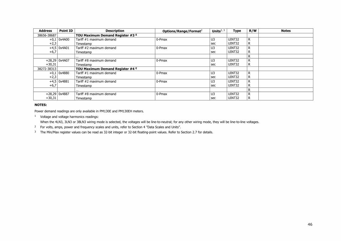
46
Address Point ID Description Options/Range/Format2 Units2, 3 Type R/W Notes
38656-38687 TOU Maximum Demand Register #3 E
+0,1 +2,3
0x4A00 Tariff #1 maximum demand
Timestamp
0-Pmax U3 sec
UINT32 UINT32
R R
+4,5 +6,7
0x4A01 Tariff #2 maximum demand
Timestamp
0-Pmax U3 sec
UINT32 UINT32
R R
… R
+28,29 +30,31
0x4A07 Tariff #8 maximum demand
Timestamp
0-Pmax U3 sec
UINT32 UINT32
R R
38272-38313 TOU Maximum Demand Register #4 E
+0,1 +2,3
0x4880 Tariff #1 maximum demand
Timestamp
0-Pmax U3 sec
UINT32 UINT32
R R
+4,5 +6,7
0x4881 Tariff #2 maximum demand
Timestamp
0-Pmax U3 sec
UINT32 UINT32
R R
… R
+28,29 +30,31
0x4887 Tariff #8 maximum demand
Timestamp
0-Pmax U3 sec
UINT32 UINT32
R R
NOTES:
Power demand readings are only available in PM130E and PM130EH meters.
1 Voltage and voltage harmonics readings:
When the 4LN3, 3LN3 or 3BLN3 wiring mode is selected, the voltages will be line-to-neutral; for any other wiring mode, they will be line-to-line voltages.
2 For volts, amps, power and frequency scales and units, refer to Section 4 ”Data Scales and Units”.
3 The Min/Max register values can be read as 32-bit integer or 32-bit floating-point values. Refer to Section 2.7 for details.

47
3.6 Device Control and Status Registers
Address Point ID Description Options/Range Units Type R/W Notes
Device Restart Register
2560 Warm restart of the device 0 when read, 0xFFFF when written = restart the device
UINT16 R/W
Device Authorization Registers
2575 When write: 4-digit password. When read: 0 = access permitted, -1 = authorization required.
0-9999 (write) 0/-1 (read)
INT16 R/W
44378-44379 When write: 8-digit password. When read: 0 = access permitted, -1 = authorization required.
0 - 99999999 (write) 0/-1 (read)
INT32 R/W
Remote Relay Control
3244-3247
+0 Remote relay command 0 = remove a remote command 1 = operate relay 2 = remove a remote command and release a locally latched relay
UINT16 W
3244 RO1 Control
3245 RO2 Control
3246 RO3 Control
3247 RO4 Control
Device Reset/Clear Registers
3404 Clear total energy registers 0 UINT16 W
3405 Clear total maximum demand registers 0 = Clear all maximum demands 1 = Clear power demands E 2 = Clear volt, ampere and harmonic demands
UINT16 W
3406 Clear TOU energy registers E 0 UINT16 W
3407 Clear TOU maximum demand registers E 0 UINT16 W
3408 Clear pulse counters 0 = Clear all counters 1-4 = Clear counter #1-#4
UINT16 W
3409 Clear Min/Max log 0 UINT16 W
3414 Clear operation/event counters 6=reset communication counters UINT16 W
Device Identification
2561-2562 Reserved 0 UINT16 R
2563 Firmware build number 1-99 UINT16 R
2564 Reserved 0 UINT16 R
2565 Firmware version number 1100-1199 UINT16 R Two higher decimal digits = major version number, two lower decimal digits = minor version number
2566,2567 Instrument options F28 UINT32 R
3484 Current serial port number 0=COM1, 1=COM2 UINT16 R

48
Address Point ID Description Options/Range Units Type R/W Notes
Device Status Registers
3452 Relay status 0x0000-0x000F UINT16 R Bitmap: 0=open, 1= closed
3453 Reserved 0 UINT16 R
3454 Digital (status) inputs 0x0000-0x0FFF UINT16 R Bitmap: 0=open, 1=closed
3455 Present setpoint status 0x0000-0xFFFF UINT16 R Bitmap: 0=released, 1=operated
Alarm Notification Registers
3474 Latched setpoint SP1-SP16 alarm status. Nonvolatile register.
0x0000-0xFFFF UINT16 R/W Bitmap: Read - 1=setpoint has been operated at least once since last reset; Write – 0=clear alarm, 1=has no effect.
3475-3476 Device diagnostics. Nonvolatile register. F23 UINT16 R/W Bitmap: Read – 1=diagnostic failed at least once since last reset; Write – 0=clear diagnostic flag, 1=has no effect.
DI Change Events
4368-4397
+0,1 Timestamp, seconds since 1/1/1970 F1 sec UINT32 R
+2,3 Timestamp, seconds fraction, µsec 0-999000 µsec UINT32 R
+4 DI number 0-11 = DI1-DI12 UINT16 R
+5 DI status 0=open, 1=closed UINT16 R
4368-4373 Event 1 (oldest)
4374-4379 Event 2
4380-4385 Event 3
4386-4391 Event 4
4392-4397 Event 5 (most recent)
Memory Status Registers
44262-44263 Memory size, bytes 59520 UINT32 R
44264-44265 Free memory, bytes UINT32 R
44266-44277 Reserved UINT32 R
Log Notification Registers (bit map)
44278-44279 0 = no new logs, 1 = new record logged 0x00000000 - 0x0001FFFF UINT32 R
Communication Status
44394 Cellular received signal strength (RSSI), dBm 0 = not known or not detectable, 51-113 = -51 to -113 dBm
UINT16 R
44395 Cellular connection status 0 = not connected, 1 = not registered, 2 = registered
UINT16 R
44396 WiFi signal quality. % 0 = not known or not detectable, 1-100 %
UINT16 R
44397 WiFi connection status 0 = not connected, 1 = connected
UINT16 R

49
Address Point ID Description Options/Range Units Type R/W Notes
44398-44409 Reserved UINT16 R 65535 = N/A
Communication Counters
44410 Successful eXpertPower client connections 0-65534 UINT16 R
44411 Failed eXpertPower client connections 0-65534 UINT16 R
44412 Successful TCP notification client connections 0-65534 UINT16 R
44413 Failed TCP notification client connections 0-65534 UINT16 R
44414-44441 Reserved UINT16 R 65535 = N/A

50
3.7 Device Setup Registers
Address Point ID Description Options/Range Units Type R/W Notes
Device Identification
46080-46111
+0,1 Device serial number 0-999999 UINT32 R
+2,3 Device model ID 13010=PM130P, 13011=PM130A, 13020=PM130E, 13030-13032=PM130EH
UINT32 R
+4-11 Device model name “PM130P”, “PM130E”,“PM130EH” CHAR16 R Null-terminated string
+12-13 Device options (bitmap) 0 UINT32 R
+14-19 Reserved UINT16 R
+20 Device firmware version number 1101-1199
UINT16 R Two higher decimal digits = major version number, two lower decimal digits = minor version number
+21 Device firmware build number 1-99 UINT16 R
+22,23 Reserved UINT16 R
+24 Boot loader version number 0101-0199 UINT16 R Two higher decimal digits = major version number, two lower decimal digits = minor version number
+25 Boot loader build number 1-99 UINT16 R
+26-31 Reserved UINT16 R
Factory Device Settings
46112-46178
+0 V1-V3 input range 690, 120 (option U) V UINT16 R Does not limit the 690V input range
+1 V1-V3 input overload 120 % UINT16 R
+2,3 Reserved UINT16 R
+4 I1-I3 input range 1, 5 A UINT16 R
+5 I1-I3 input overload 200 % UINT16 R
+6-13 Reserved UINT16 R
+14-63 Unused UINT16
+64 Ethernet MAC address 0-1 0x0500 UINT16 R
+65 Ethernet MAC address 2-3 0x00F0 UINT16 R
+66 Ethernet MAC address 4-5 0x0000-0xFFFF UINT16 R
Basic Setup
2304-2324
+0 Wiring mode F26 UINT16 R/W
+1 PT ratio 10 to 65000 0.1 UINT16 R/W
+2 CT primary current 1 to 50,000 A UINT16 R/W
+3 Power block demand period E 1,2,3,5,10,15,20,30,60 min, 255 = external synchronization
min UINT16 R/W If the external synchronization is selected, the DI1 input is considered a pulse or KYZ input.

51
Address Point ID Description Options/Range Units Type R/W Notes
The pulse edge restarts the power demand block accumulation interval. E
+4 Volt/ampere demand period 0 to 1800 sec UINT16 R/W
+5-7 Reserved UINT16 R/W Read as 65535
+8 Number of blocks in a sliding window E 1 to 15 UINT16 R/W E
+9,10 Reserved UINT16 R/W Read as 65535
+11 Nominal line frequency 25, 50, 60, 400 Hz UINT16 R/W
+12 Maximum demand load current 0 to 50,000 (0=CT primary current) A UINT16 R/W
+13-19 Reserved UINT16 R/W Read as 65535
+20 PT ratio multiplication factor 1, 10 UINT16 R/W
Communication Ports Setup
2344-2359
+0 Communication protocol COM1: 0=SATEC ASCII, 1=Modbus RTU, 2=DNP3.0 COM2: 0=SATEC ASCII, 1=Modbus RTU, 2=DNP3.0, 5=Profibus DP
UINT16 R/W
+1 Interface COM1: 2=RS-485 COM2: 0=RS-232, 1=RS-422, 2=RS-485, 5=RF, 6=Ethernet, 7=Profibus
UINT16 R/W
+2 Device address SATEC ASCII: 0-99 Modbus RTU: 1-247 DNP3.0: 0–65532 Profibus DP: 0-126
UINT16 R/W
+3 Baud rate 1=300 bps, 2=600 bps, 3=1200 bps, 4=2400 bps, 5=4800 bps, 6=9600 bps, 7=19200 bps, 8=38400 bps, 9=57600 bps, 10=115200 bps
UINT16 R/W
+4 Data format 0=7 bits/even parity, 1=8 bits/no parity, 2=8 bits/even parity
UINT16 R/W
+5 Flow control 0=no flow control 1=software (XON/XOFF) 2=hardware (CTS)
UINT16 R/W N/A for COM1 (read as 65535)
+6 RTS mode 0=not used, 1=RTS is permanently asserted 2=RTS is asserted during the transmission
UINT16 R/W N/A for COM1 (read as 65535)
+7 ASCII compatibility mode 0=disabled, 1=enabled UINT16 R/W
2344-2351 COM1 Setup
2352-2359 COM2 Setup

52
Address Point ID Description Options/Range Units Type R/W Notes
Device Options Setup
2376-2390
+0 Power calculation mode 0=using reactive power: S=f(P,Q), 1=using non-active power: Q=f(S,P)
UINT16 R/W
+1 Energy roll value E 0=1104, 1=1105, 2=1106,
3=1107, 4=1108, 5=1109
UINT16 R/W Default 1108
+2 Phase energy calculation mode E 0=disabled, 1=enabled UINT16 R/W
+3-9 Reserved UINT16 R/W Read as 65535
+10 Energy LED test mode E 0=disabled, 1=Wh test, 2=varh test UINT16 R/W LED pulse rate is 10,000 pulses/kWh
+11 Starting voltage, percent of FS voltage 15-50 0.1% UINT16 R/W Default 1.5%
+12-13 Reserved UINT16 R/W Read as 65535
+14 Device resolution (see Section 4 for details) 0 = Low resolution, 1 = High resolution
UINT16 R/W Default 0
Local Settings
4320-4330
+0 Daylight savings time (DST) option 0 = DST disabled (standard time only), 1 = DST enabled
UINT16 R/W
+1 DST start month 1-12 UINT16 R/W
+2 DST start week of the month 1-4 = 1st, 2nd, 3rd and 4th week, 5=the last week of the month
UINT16 R/W
+3 DST start weekday 1-7 (1=Sun, 7=Sat) UINT16 R/W
+4 DST end month 1-12 UINT16 R/W
+5 DST end week of the month 1-4=1st, 2nd, 3rd and 4th week, 5=the last week of the month
UINT16 R/W
+6 DST end weekday 1-7 (1=Sun, 7=Sat) UINT16 R/W
+7 Clock synchronization source 1-12 = DI1-DI12, 32767 = meter clock
UINT16 R/W A DI input is considered a pulse or KYZ input. The pulse edge adjusts the clock at the nearest whole minute.
+8 Country code ITU calling number UINT16 R/W
+9 DST start hour 1-6 UINT16 R/W
+10 DST end hour 1-6 UINT16 R/W
Clock Indication and Setup
4352-4358
+0 Seconds 0-59 UINT16 R/W
+1 Minutes 0-59 UINT16 R/W
+2 Hour 0-23 UINT16 R/W
+3 Day of month 1-31 UINT16 R/W
+4 Month 1-12 UINT16 R/W
+5 Year (calendar year minus 2000) 0-99 UINT16 R/W
+6 Weekday 1-7 (1=Sun, 7=Sat) UINT16 R/W Ignored when written

53
Address Point ID Description Options/Range Units Type R/W Notes
Alarm/Event Setpoints Setup
2576-2703
+0 Trigger parameter ID F12 UINT16 R/W
+1 Action F14 UINT16 R/W
+2 Operate delay 0-9999 0.1 sec UINT16 R/W
+3 Release delay 0-9999 0.1 sec UINT16 R/W
+4,5 Operate limit See Section 3.3 UINT32 R/W Scaled value
+6,7 Release limit See Section 3.3 UINT32 R/W Scaled value
2576-2583 Setpoint #1
2584-2591 Setpoint #2
2592-2599 Setpoint #3
2600-2607 Setpoint #4
2608-2615 Setpoint #5
2616-2623 Setpoint #6
2624-2631 Setpoint #7
2632-2639 Setpoint #8
2640-2647 Setpoint #9
2648-2655 Setpoint #10
2656-2663 Setpoint #11
2664-2671 Setpoint #12
2672-2679 Setpoint #13
2680-2687 Setpoint #14
2688-2695 Setpoint #15
2696-2703 Setpoint #16
Pulse Counters Setup
2940-2947
+0 Source digital input ID 0=not assigned, 1-12=DI1-DI12 UINT16 R/W
+1 Multiplier 0-9999 UINT16 R/W
2940-2941 Counter #1 Setup
2942-2943 Counter #2 Setup
2944-2945 Counter #3 Setup
2946-2947 Counter #4 Setup
Analog Outputs Setup
3148-3153
+0 Output parameter ID F18 UINT16 R/W
+1 Zero scale value (0/4 mA) See Section 3.3 UINT16 R/W Scaled value
+2 Full scale value (1/20 mA) See Section 3.3 UINT16 R/W Scaled value
3148-3150 AO1 Setup
3151-3153 AO2 Setup
Network Setup
46576-46703
+0,1 Device IP Address 0x01000000-0xFFFFFFFF UINT32 R/W Network byte order

54
Address Point ID Description Options/Range Units Type R/W Notes
+2,3 Network subnet mask 0x00000001-0xFFFFFFFF UINT32 R/W Network byte order
+4,5 Network default gateway 0x00000000-0xFFFFFFFF UINT32 R/W Network byte order
+6,7 Use DHCP 0 = NO, 1 = YES UINT32 R/W
+8,9 TCP service port 502 = Modbus/TCP, 20000 = DNP3.0/TCP
UINT32 R/W
+10-127 Reserved R/W
WiFi Station Setup
59178-59211
+0-7 Network name (SSID) 1-15 ASCII characters CHAR16 R/W
+8,9 Security/encryption type 0=Unsecured, 1=Open/WEP, 2=Shared/WEP, 3=WPA/TKIP, 4=WPA/AES, 5=WPA/TKIP+AES
UINT32 R/W
+10-17 Security key WEP: 5 or 13 ASCII characters TKIP/AES: 8-15 ASCII characters
CHAR16 R/W
+18-33 Reserved R/W
WiFi Access Point Setup
59212-59253
+0,1 Access point enable 0=disabled, 1=enabled UINT32 R/W
+2,3 WiFi protocol 0=802.11b, 1=802.11g, 2=802.11n, 3=802.11b/g, 4=802.11b/g/n
UINT32 R/W
+4,5 LAN IP address 0x01000000-0xFFFFFFFF UINT32 R/W Network byte order
+6,7 LAN subnet mask 0x00000001-0xFFFFFFFF UINT32 R/W Network byte order
+8-15 Network name (SSID) 1-15 ASCII characters CHAR16 R/W
+16,17 Security/encryption type 0=Unsecured, 1=Open/WEP, 2=Shared/WEP, 3=WPA/TKIP, 4=WPA/AES, 5=WPA/TKIP+AES
UINT32 R/W
+18-25 Security key WEP: 5 or 13 ASCII characters TKIP/AES: 8-15 ASCII characters
CHAR16 R/W
+26,27 WiFi channel 0=auto, 1-11=CH1-CH11 UINT32 R/W
+28-41 Reserved R/W
Password Setup
46704-46707
+0,1 Communications password (4 digits) 0-9999 UINT32 R/W Read as 0
+2 Password protection enabled 0 = disabled, 1 = enabled UINT16 R/W
+3 Reserved UINT16 R/W
Expert Power Service Setup
46768-46783
+0,1 Expert Power server IP Address 0x01000000-0xFFFFFFFF UINT32 R/W Default = 207.232.60.18
+2,3 Expert Power server TCP service port 0-65535 UINT32 R/W Default = 5001
+4,5 Expert Power client enabled 0 = client disabled, 1 = client enabled
UINT32 R/W
+6,7 Time to next session 1-99999 min UINT32 R/W
+8,9 Time to next session 1-99999 min UINT32 R Same as previous

55
Address Point ID Description Options/Range Units Type R/W Notes
+10-15 Reserved
Internet Service Provider (ISP) accounts
46784-46831
+0-15 ISP telephone number CHAR32 R/W
+16-31 Login name CHAR32 R/W
+32-47 Login password CHAR32 R/W
GPRS Setup
46832-46879
+0-15 Access Point Name (APN) CHAR32 R/W
+16-31 User name CHAR32 R/W
+32-39 Password CHAR16 R/W
+40-47 Reserved CHAR16 R/W
TCP Notification Client Setup
46896-46991
+0,1 Client enabled 0 = disabled, 1 = enabled UINT32 R/W
+2,3 Server address 0x01000000-0xFFFFFFFF UINT32 R/W
+4,5 Server port 0-65535 UINT32 R/W
+6,7 Message exchange address 0-65535 UINT32 R/W
+8-15 Reserved
Transformer Correction Setup
47072-47099
+0 Ratio correction factor 700-1300 0.001 UINT16 R/W
+1 Phase angle error -600 to 600 min INT16 R/W
+2, 3 Reserved INT16 R/W
47072-47075 V1 transformer correction
47076-47079 V2 transformer correction
47080-47083 V3 transformer correction
47084-47087 Reserved
47088-47091 I1 transformer correction
47092-47095 I2 transformer correction
47096-47099 I3 transformer correction
IEC 60870-5 Options Setup
49460-49494
+0 Maximum length of variable frame, octets 32-255 UINT16 R/W
+1 Link address length, octets 1-2 UINT16 R/W
+2 Cause of transmission length, octets 1-2 UINT16 R/W
+3 Length of common address of ASDU, octets 1-2 UINT16 R/W
+4 Length of information object address, octets 1-3 UINT16 R/W
+5 Select-before-operate timeout, s 0-30 UINT16 R/W
+6 Short pulse duration, ms 100-3000 ms UINT16 R/W
+7 Long pulse duration, ms 100-3000 ms UINT16 R/W
+8,9 Time synchronization period, s 1-86400, 0=not active s UINT32 R/W
+10 Local counter freeze period, min 1-60, 0=not active min UINT16 R/W

56
Address Point ID Description Options/Range Units Type R/W Notes
+11 Cyclic data transmission period, ms 100-30000, 0=not active ms UINT16 R/W
+12,13 Client IP address for cyclic data transmission 0-0xFFFFFE, 0=not active UINT32 R/W
+14,15 Client IP address for spontaneous transmission 0-0xFFFFFE, 0=not active UINT32 R/W
+16,17 Not used 0 UINT32 R/W
+18 Not used 0 UINT16 R/W
+19 Respond with class 1 data to class 2 requests 0=disabled, 1=enabled UINT16 R/W
+20 Single point start mapped address 1-4095 UINT16 R/W
+21 Single point default static object type F30 UINT16 R/W
+22 Single point default event object type F31 UINT16 R/W
+23 Double point start mapped address 1-4095 UINT16 R/W
+24 Double point default static object type F32 UINT16 R/W
+25 Double point default event object type F33 UINT16 R/W
+26 Measured value start mapped address 1-4095 UINT16 R/W
+27 Measured value default static object type F34 UINT16 R/W
+28 Measured value default event object type F35 UINT16 R/W
+29 Integrated totals start mapped address 1-4095 UINT16 R/W
+30 Integrated totals default static object type F36 UINT16 R/W
+31 Integrated totals default event object type F37 UINT16 R/W
+32 Voltage units 0=V, 1=kV UINT16 R/W
+33 Current units 0=A, 1=kA UINT16 R/W
+34 Power units 0=kW, 1=MW UINT16 R/W
IEC 60870-5 Class 2 Data and Counters Setup
49524-49619
+0 Information object type and flags Bits 0:7 – static object type identification (F30, F32, F34, F36), Bit 8=1 – freeze with reset, Bit 9=1 – local freeze, Bit 10=1 – cyclic data transmission, Bit 11=1 – general interrogation, Bits 12:15 – interrogation group = 0-15 (0=no group assigned)
+1 Start information object address 1-65535 UINT16 R/W
+2 Number of elements in the range 1-128 UINT16 R/W
49524-49526 Object address range #1
49527-49529 Object address range #2
… …
49617-46619 Object address range #32
IEC 60870-5 Assignable Point Map and Events Setup
49716-49971 UINT16 R/W
+0 Point ID See Section 3.4 UINT16 R/W
+1 Information object type and flags Bits 0:7 – static object type identification (F3, F5, F7), Bits 8:9 – relation (0=delta, 1= more than, 2 = less than)
UINT16 R/W

57
Address Point ID Description Options/Range Units Type R/W Notes
Bit 10=1 – class 1 assignment
+2,3 Deadband/threshold See Section 3.4 for the point range and resolution
INT32 R/W
49716-49719 Mapped static/event point #1
49720-49723 Mapped static/event point #2
… …
49968-49971 Mapped static/event point #64
DNP Options Setup
51158-51183
+0 Default Binary Input Static object variation F24 (default 0) UINT16 R/W
+1 Reserved UINT16 R/W
+2 Default Binary Counter object variation F24 (default 3) UINT16 R/W
+3 Default Frozen Binary Counter object variation F3 (default 4) UINT16 R/W
+4-5 Reserved UINT16 R/W
+6 Default Analog Input object variation F24 (default 3) UINT16 R/W
+7-10 Reserved UINT16 R/W
+11 16-bit BC scaling 0=1 (default), 1=10, 2=100,
3=1000
UINT16 R/W
+12 16-bit AI scaling 0=scaling is OFF, 1=scaling is ON UINT16 R/W
+13-5 Reserved UINT16 R/W
+16 Select/Operate Timeout 2 to 30 seconds (default 10 sec) UINT16 R/W
+17 Multi Fragment Interval 5 to 500 ms (default 10 ms) UINT16 R/W
+18-21 Reserved Read as 65535 UINT16 R/W
+22,23 Time Sync Period 0 to 86400 seconds (default 86400 sec)
UINT32 R/W
51184-51189 Reserved
DNP Class 0 Point Assignments
51702-51797
+0 DNP object and variation F25 UINT16 R/W
+1 DNP point number Point number for the selected object UINT16 R/W
+2 Number of points 0-128 UINT16 R/W
51702-51704 DNP Class 0 Points Range 1
51705-51707 DNP Class 0 Points Range 2
…
51795-51797 DNP Class 0 Points Range 32
51798-51893 Reserved
File Setup E
52598-52767
+0 File type 0 UINT16 R/W
+1 File attributes (bitmap) F3 UINT16 R/W
+2 Number of records in the file 0-65535 (0 = delete file) UINT16 R/W
+3 Number of sections/channels in the file 0-8 UINT16 R/W 0 = non-partitioned file
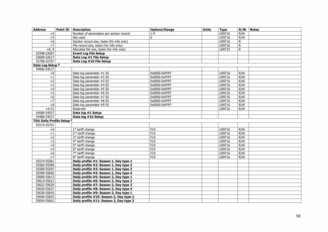
58
Address Point ID Description Options/Range Units Type R/W Notes
+4 Number of parameters per section record 1-9 UINT16 R/W
+5 Not used 0 UINT16 R/W
+6 Section record size, bytes (for info only) UINT16 R
+7 File record size, bytes (for info only) UINT16 R
+8, 9 Allocated file size, bytes (for info only) UINT32 R
52598-52607 Event Log File Setup
52608-52617 Data Log #1 File Setup
52758-52767 Data Log #16 File Setup
Data Log Setup E
54006-54517
+0 Data log parameter #1 ID 0x0000-0xFFFF UINT16 R/W
+1 Data log parameter #2 ID 0x0000-0xFFFF UINT16 R/W
+2 Data log parameter #3 ID 0x0000-0xFFFF UINT16 R/W
+3 Data log parameter #4 ID 0x0000-0xFFFF UINT16 R/W
+4 Data log parameter #5 ID 0x0000-0xFFFF UINT16 R/W
+5 Data log parameter #6 ID 0x0000-0xFFFF UINT16 R/W
+6 Data log parameter #7 ID 0x0000-0xFFFF UINT16 R/W
+7 Data log parameter #8 ID 0x0000-0xFFFF UINT16 R/W
+8 Data log parameter #9 ID 0x0000-0xFFFF UINT16 R/W
+9-31 Reserved UINT16 R/W
54006-54037 Data log #1 Setup
54486-54517 Data log #16 Setup
TOU Daily Profile Setup E
55574-55701
+0 1st tariff change F10 UINT16 R/W
+1 2nd tariff change F10 UINT16 R/W
+2 3rd tariff change F10 UINT16 R/W
+3 4th tariff change F10 UINT16 R/W
+4 5th tariff change F10 UINT16 R/W
+5 6th tariff change F10 UINT16 R/W
+6 7th tariff change F10 UINT16 R/W
+7 8th tariff change F10 UINT16 R/W
55574-55581 Daily profile #1: Season 1, Day type 1
55582-55589 Daily profile #2: Season 1, Day type 2
55590-55597 Daily profile #3: Season 1, Day type 3
55598-55605 Daily profile #4: Season 1, Day type 4
55606-55613 Daily profile #5: Season 2, Day type 1
55614-55621 Daily profile #6: Season 2, Day type 2
55622-55629 Daily profile #7: Season 2, Day type 3
55630-55637 Daily profile #8: Season 2, Day type 4
55638-55645 Daily profile #9: Season 3, Day type 1
55646-55653 Daily profile #10: Season 3, Day type 2
55654-55661 Daily profile #11: Season 3, Day type 3

59
Address Point ID Description Options/Range Units Type R/W Notes
55662-55669 Daily profile #12: Season 3, Day type 4
55670-55677 Daily profile #13: Season 4, Day type 1
55678-55685 Daily profile #14: Season 4, Day type 2
55686-55693 Daily profile #15: Season 4, Day type 3
55694-55701 Daily profile #16: Season 4, Day type 4
55702-55711 Reserved
TOU Calendar Setup E
55712-56031
+0-9 Calendar entry record R/W
+0 Daily profile 0-3 = Season 1, Day types 0-3 4-7 = Season 2, Day types 0-3 8-11 = Season 3, Day types 0-3 12-15 = Season 4, Day types 0-3
UINT16 R/W
+1 Week of month 0=all, 1=1st, 2=2nd, 3=3rd, 4=4th, 5=last week of the month
UINT16 R/W
+2 Weekday 0=all, 1-7 (Sun=1, Sat=7) UINT16 R/W
+3 Till Weekday 0=all, 1-7 (Sun=1, Sat=7) UINT16 R/W
+4 Month 0=all, 1-12=January - December UINT16 R/W
+5 Day of month 0=all, 1-31=day 1-31 UINT16 R/W
+6 Till Month 0=all, 1-12=January - December UINT16 R/W
+7 Till Day of month 0=all, 1-31=day 1-31 UINT16 R/W
+8-9 Reserved UINT16 R/W
55712-55721 Calendar entry #1
55722-55731 Calendar entry #2
55732-55741 Calendar entry #3
…
56022-56031 Calendar entry #32
56032-56191 Reserved
Summary Energy/TOU Registers Setup E
56672-56703
+0 Not used UINT16 R/W
+1 Units of measurement 0=none, 1=kWh, 2=kvarh, 3=kVAh,
4=m3, 5=CF (cubic feet), 6=CCF (hundred cubic feet)
UINT16 R/W
+2 Flags (bitmap) Bit 0=1 - TOU enabled UINT16 R/W
+3 Not used 0 UINT16 R/W
56672-56675 Register #1 Setup
56676-56679 Register #2 Setup
56680-56683 Register #3 Setup
56684-56687 Register #4 Setup
Summary Energy/TOU Registers Source Setup E
56928-57183
+0 Energy source ID F11 UINT16 R/W

60
Address Point ID Description Options/Range Units Type R/W Notes
+1 Target summary register number 0-7 = register #1-#8 UINT16 R/W
+2,3 Multiplier 0-1000000 0.001 INT32 R/W
56928-56931 Energy Source #1
56932-56935 Energy Source #2
56936-56939 Energy Source #3
56940-56943 Energy Source #4
Digital Inputs Setup
61728-61775
+0 Pulse mode 0 = pulse, 1 = KYZ UINT16 R/W
+1 Polarity Bit 0 – pulse polarity: 0=normal, 1=inverting Bit 1 – input polarity: 0=normal, 1=inverting
UINT16 R/W
+2 De-bounce time, ms 1-100 UINT16 R/W The same debounce time is set in groups of 4 inputs
+3 Reserved UINT16 R/W
61728-61731 DI1 Setup
61732-61735 DI2 Setup
…
61772-61775 DI12 Setup
Relay Outputs Setup
61984-62007
+0 Operation Mode 0=unlatched, 1=latched, 2=pulse, 3=KYZ
UINT16 R/W
+1 Polarity 0=normal, 1=inverting UINT16 R/W
+2 Pulse width, ms 1-1000 UINT16 R/W
+3 Pulse source ID E F17 UINT16 R/W
+4 Units per pulse 1-10000 x0.1 UINT16 R/W
+5 Reserved UINT16 R/W
61984-61989 RO1 Setup
61990-61995 RO2 Setup
61996-62001 RO3 Setup
62002-62007 RO4 Setup
Analog Outputs Setup
62560-62571
+0 Output parameter ID F18 UINT16 R/W
+1 Not used 0 UINT16 R/W
+2,3 Zero scale value (0/4 mA) See Section 3.4 INT32 R/W
+4,5 Full scale value (20/1 mA) See Section 3.4 INT32 R/W
62560-62565 AO1 Setup
62566-62571 AO2 Setup

61
3.8 Analog and Digital I/O Configuration
Address Point ID Description Options/Range Units Type R/W Notes
I/O Slots Configuration Info
63008-63055
+0 I/O type F29 UINT16 R
+1 Number of I/Os on the slot 0-4 UINT16 R
+2 First I/O number on the slot 0 UINT16 R
+3 Last I/O number on the slot 0-4 UINT16 R
63008-63011 DI Slot Configuration
63012-63015 RO Slot Configuration
63016-63019 AI/AO Slot Configuration
63020-63055 Reserved
I/O Type Info
63056-63119
+0 Number of I/O slots of this type 0-1 UINT16 R
+1 Total number of I/O's of this type 0-4 UINT16 R
+2 Number of I/O's on the slot 0-4 UINT16 R
+3 Not used 0 UINT16 R
63056-63059 DI Type Info
63060-63063 RO Type Info
63064-63067 AI Type Info
63068-63071 AO Type Info
63076-63119 Reserved

62
3.9 File Transfer Registers E
Address Point ID Description Options/Range Units Type R/W Notes
File Transfer Control Blocks
63120-63151 File Request Block
+0 File function 1 = ACK - acknowledgement 3 = set file position 5 = reset file position 7 = find 11 = read file 127 = erase file
UINT16 R/W 1 - clears the file transfer block 3 - changes the file position 5 - sets the file position at the first (oldest) record 7 - finds a record matching an event or/and time (see Note 3) 11 - opens the file for reading from the present file position
+1 File ID F2 UINT16 R/W
+2 Section number (functions 3, 5, 11) 0-7, 0xFFFF = use channel ID UINT16 R/W
+3 Section channel ID (functions 3, 5, 11) F6, F7 UINT16 R/W
+4 Record sequence number (functions 3, 11) 0-65535 UINT16 R/W The record sequence number with function 11 does not change the file position (see Note 2).
+5 Request variation (function 11) 0 UINT16 R/W See file response headings
+6 Find key: N/A UINT16 R/W
+7 Find key: N/A UINT16 R/W
+8, 9 Find key: Start time, seconds since 1/1/1970 F1 sec UINT32 R/W Note 3
+10, 11 Find key: Start time, fractional seconds in µsec µsec UINT32 R/W Note 3
+12, 13 Find key: End time, seconds since 1/1/1970 F1 sec UINT32 R/W Note 3
+14, 15 Find key: End time, fractional seconds in µsec µsec UINT32 R/W Note 3
+16-31 Reserved UINT16 R/W
63152-63799 File Response Block
Data transfer area [0 – 647] UINT16 R
64944-64951 File Info Request Block
+0 File function 9 = read file info UINT16 R/W
+1 File ID F2 UINT16 R/W
+2 Section number 0-7, 0xFFFF = use channel ID UINT16 R/W
+3 Section channel ID F6, F7 UINT16 R/W
+4 Not used 0 UINT16 R/W
+5 Request variation 0, 1, 2 UINT16 R/W
+6-7 Reserved UINT16 R/W
64952-65151 File Info Response Block
Data transfer area [0 - 199] UINT16 R
NOTES:
1. File sections for partitioned (multi-section) files, like Summary/TOU profile log files, can be requested either by a section number, or by a section channel ID. If a section number is set to 0xFFFF, the section channel ID will be used to identify the section. The section number will be returned in the response block. If a section number is written, then the corresponding channel ID will be returned in the file response block.

63
2. The record sequence number with function 11 (Read-File) does not change the file position and is used only as a reference to track the order of records. The file transfer block will continue to hold the same data until it is acknowledged, or until the file position is explicitly moved to another record. For multi-section, the Read-File request, which addresses a different file section, will refill the transfer block with data of the record from the requested file section with the identical sequence number. After acknowledgment, the file position will be moved to the next record.
3. Function 7 (Find) puts into the file request block the sequence number of the first record in the file that matches the event time. Any one of the find keys can be omitted by setting it to 0. If one or a number of find keys are omitted, the device will use the remaining keys to locate the matching record. If the record could not be found, the device responds to the write request with the exception code 3 (illegal data). The status of the operation can be read through the file status word in the file info block.
File Response Blocks
Address Point ID Description Options/Range Units Type R/W Notes
File Info Response Block (Variation 0 – File info)
64952-64959 Block Heading
+0 File function 9 UINT16 R
+1 File ID 16 UINT16 R
+2 Section number 0-31 UINT16 R
+3 Section channel ID F6, F7 UINT16 R
+4 Maximum number of records in the block 1 UINT16 R
+5 Record size, words 36 UINT16 R
+6 Request variation 0 UINT16 R
+7 Reserved 0 UINT16 R
64960-64997 File Info
+0 File type 0 UINT16 R
+1 File attributes F3 UINT16 R
+2 File (section) status F4 UNT16 R
+3 Number of sections in the file 0-32 UINT16 R 0 = non-partitioned file
+4,5 File channel mask (channels 1-32), bitmap F8, F9 UINT32 R
+6,7 File channel mask (channels 33-64), bitmap F8, F9 UINT32 R
+8 Number of records in the file 0-65535 UINT16 R
+9 Number of records until the end of the file 0-65535 UINT16 R
+10 Current record (read position) sequence number 0-65535 UINT16 R
+11 Current write position sequence number 0-65535 UINT16 R
+12 First (oldest) record sequence number 0-65535 UINT16 R
+13 Last (newest) record sequence number 0-65535 UINT16 R
+14,15 Last record time, seconds since 1/1/1970 F1 sec UINT32 R
+16,17 Last record time, fractional seconds µsec UINT32 R
+18,19 First record time, seconds since 1/1/1970 F1 sec UINT32 R
+20,21 First record time, fractional seconds µsec UINT32 R
+22,23 Null 0 UINT32 R
+24,25 Null 0 µsec UINT32 R
+26,27 Null 0 sec UINT32 R
+28,29 Null 0 µsec UINT32 R
+30 Maximum number of records 0-65535 UINT16 R
+31 Number of parameters per data section record 0-16 UINT16 R

64
Address Point ID Description Options/Range Units Type R/W Notes
+32 Section record size, bytes Byte UINT16 R
+33 File record size, bytes Byte UINT16 R
+34,35 Allocated file size, bytes Byte UINT32 R
File Info Response Block (Variation 1 – Current record info)
64952-64959 Block Heading
+0 File function 9 UINT16 R
+1 File ID F2 UINT16 R
+2 Section number 0-31 UINT16 R
+3 Section channel ID F6, F7 UINT16 R
+4 Maximum number of records in the block 1 UINT16 R
+5 Record size, words 8 UINT16 R
+6 Request variation 1 UINT16 R
+7 Reserved 0 UINT16 R
64960-64997 File Info
+0 File (section) status F4 UNT16 R
+1 Number of records in the file 0-65535 UINT16 R
+2 Number of records until the end of the file 0-65535 UINT16 R
+3 Current record (read position) sequence number 0-65535 UINT16 R
+4,5 Current record time, seconds since 1/1/1970 F1 sec UINT32 R
+6,7 Current record time, fractional seconds µsec UINT32 R
File Info Response Block (Variation 2 – Data log record structure)
64952-64959 Block Heading
+0 File function 9 UINT16 R
+1 File ID 1,16 UINT16 R
+2 Section number 0-7 UINT16 R
+3 Section channel ID F6, F7 UINT16 R
+4 Number of records in the block 1 UINT16 R
+5 Record size, words 18 UINT16 R
+6 Request variation 2 UINT16 R
+7 Reserved 0 UINT16 R
64960-64997 File Info
+0 Not used 0 UINT16 R
+1 Number of fields in a data record 1-9 UINT16 R
+2 Field 1 parameter ID 0-0xFFFF UINT16 R
+3 Field 2 parameter ID 0-0xFFFF UINT16 R
…
+10 Field 9 parameter ID 0-0xFFFF UINT16 R
Event Log Response Block
63152-63159 Block Heading
+0 Last file function 1, 3, 5, 11 UINT16 R
+1 File ID 0 UINT16 R
+2 Section number 0 UINT16 R
+3 Section channel ID 0 UINT16 R

65
Address Point ID Description Options/Range Units Type R/W Notes
+4 Maximum number of records in the block 32 UINT16 R
+5 Record size, words 12 UINT16 R
+6 Request variation 0 UINT16 R
+7 Reserved 0 UINT16 R
63160-63543 Event Log Records
+0 Record status F5 INT16 R
+1 Record sequence number 0-65535 UINT16 R
+2,3 Trigger time, seconds since 1/1/1970 F1 sec UINT32 R
+4,5 Trigger time, fractional seconds in µsec µsec UINT32 R
+6 Event number 1-65535 UINT16 R
+7 Event point/source ID F19 UINT16 R
+8 Event effect F20 UINT16 R
+9 Reserved 0 UINT16 R
+10,11 Value triggered INT32 R
63160-63171 Record #1
...
63532-63543 Record #32
Data Log Response Block
63152-63159 Block Heading
+0 Last file function 1, 3, 5, 11 UINT16 R
+1 File ID 1,16 UINT16 R
+2 Section number 0-7 UINT16 R
+3 Section channel ID F6 UINT16 R
+4 Maximum number of records in the block 8 for regular log, 4 for profile log UINT16 R
+5 Record size, words 8 + 2 Number of parameters UINT16 R
+6 Request variation 0 UINT16 R
+7 Reserved 0 UINT16 R
63160-63367 Data Log Records
+0 Record status F5 INT16 R
+1 Record sequence number 0-65535 UINT16 R
+2,3 Record time, seconds since 1/1/1970 F1 sec UINT32 R
+4,5 Record time, fractional seconds in µsec µsec UINT32 R
+6 Trigger event type F22 INT16 R
+7 Trigger event number 0 UINT16 R
+8,9 Log value #1 INT32 R
+10,11 Log value #2 INT32 R
… R
63160-… Record #1 (variable length)
...
Record #8 (variable length)
RT Waveform Response Block
63152-63159 Block Heading
+0 Last file function 1, 3, 5, 11 UINT16 R

66
Address Point ID Description Options/Range Units Type R/W Notes
+1 File ID 128 UINT16 R
+2 Section number 0-9 UINT16 R
+3 Section channel ID F7 UINT16 R
+4 Maximum number of records in the block 1 UINT16 R
+5 Record size, words 640 UINT16 R
+6 Request variation 0 UINT16 R
+7 Reserved 0 UINT16 R
63160-63799 Waveform Record
+0 Record status F5 INT16 R
+1 Record sequence number 0 UINT16 R
+2,3 Start time, seconds since 1/1/1970 F1 sec UINT32 R
+4,5 Start time, fractional seconds µsec UINT32 R
+6,7 Trigger time, seconds since 1/1/1970 F1 sec UINT32 R
+8,9 Trigger time, fractional seconds µsec UINT32 R
+10 Record series number 1-65535 UINT16 R
+11 Record serial number in a series 0-65535 UINT16 R
+12 Trigger event type 0 UINT16 R
+13 Trigger event number 0 UINT16 R
+14 Source point ID (generic) See Generic Data in Section 3.4 UINT16 R
+15 Trigger reference sample index 0–511 UINT16 R
+16 Sampling rate, µsec/sample 600-27000 0.1µsec UINT16 R
+17 Sampling rate, samples/cycle 32, 64, 128 UINT16 R
+18 Sampling frequency 4500 – 6500 0.01Hz UINT16 R
+19 Channel offset, sampling units 0 INT16 R
+20,21 Channel multiplier, primary units See Generic Data in Section 3.4 UINT32 R
+22 Channel divisor, sampling units 4095 UINT16 R
+23 Length of a sample series, data points 512 UINT16 R
+24-127 Not used 0 UINT16 R
+128 Sample Series
+128-639 Sample data series points [0...511] -4096 - 4095 INT16 R 1
1 To restore the original sampled data in the channel units (e.g., Volts, Amps), the following conversion should be applied:
DivisorChannel
MultiplierChannel)OffsetChannelSampleData(]unitsprimary[DataSampled
NOTE
If a file is read through a TCP connection, your assignments for the transfer will be effective only within the current connection socket. Since the device cannot guarantee that your next connection will be made through the same socket, you should not make any assumptions regarding the present block settings. When you open a new connection, always check the file status and pointers before reading file records.

67
3.10 Billing/TOU Daily Profile Data Log E
File Channel/
Section 1
Record
Field No. 2
Point Label Point ID
Description Range Units 3 Type Notes
0/0 Energy Register #1
1 REG1 0x1780 Summary (total) energy reading 0-999,999,999 kWh UINT32
2 TRF1 0x7000 Tariff #1 energy reading 0-999,999,999 kWh UINT32
3 TRF2 0x7001 Tariff #2 energy reading 0-999,999,999 kWh UINT32
4 TRF3 0x7002 Tariff #3 energy reading 0-999,999,999 kWh UINT32
5 TRF4 0x7003 Tariff #4 energy reading 0-999,999,999 kWh UINT32
6 TRF5 0x7004 Tariff #5 energy reading 0-999,999,999 kWh UINT32
7 TRF6 0x7005 Tariff #6 energy reading 0-999,999,999 kWh UINT32
8 TRF7 0x7006 Tariff #7 energy reading 0-999,999,999 kWh UINT32
9 TRF8 0x7007 Tariff #8 energy reading 0-999,999,999 kWh UINT32
… …
3/3 Energy Register #4
1 REG4 0x1783 Summary (total) energy reading 0-999,999,999 kWh UINT32
2 TRF1 0x7000 Tariff #1 energy reading 0-999,999,999 kWh UINT32
3 TRF2 0x7001 Tariff #2 energy reading 0-999,999,999 kWh UINT32
4 TRF3 0x7002 Tariff #3 energy reading 0-999,999,999 kWh UINT32
5 TRF4 0x7003 Tariff #4 energy reading 0-999,999,999 kWh UINT32
6 TRF5 0x7004 Tariff #5 energy reading 0-999,999,999 kWh UINT32
7 TRF6 0x7005 Tariff #6 energy reading 0-999,999,999 kWh UINT32
8 TRF7 0x7006 Tariff #7 energy reading 0-999,999,999 kWh UINT32
9 TRF8 0x7007 Tariff #8 energy reading 0-999,999,999 kWh UINT32
16/4 Daily Maximum Demand Register #1
1 REG1 MD 0x4780 Summary (total) max. demand reading 0-Pmax U3 UINT32
2 TRF1 MD 0x7100 Tariff #1 max. demand reading 0-Pmax U3 UINT32
3 TRF2 MD 0x7101 Tariff #2 max. demand reading 0-Pmax U3 UINT32
4 TRF3 MD 0x7102 Tariff #3 max. demand reading 0-Pmax U3 UINT32
5 TRF4 MD 0x7103 Tariff #4 max. demand reading 0-Pmax U3 UINT32
6 TRF5 MD 0x7104 Tariff #5 max. demand reading 0-Pmax U3 UINT32
7 TRF6 MD 0x7105 Tariff #6 max. demand reading 0-Pmax U3 UINT32
8 TRF7 MD 0x7106 Tariff #7 max. demand reading 0-Pmax U3 UINT32
9 TRF8 MD 0x7107 Tariff #8 max. demand reading 0-Pmax U3 UINT32
… …
19/7 Daily Maximum Demand Register #4
1 REG4 MD 0x4783 Summary (total) max. demand reading 0-Pmax U3 UINT32
2 TRF1 MD 0x7100 Tariff #1 max. demand reading 0-Pmax U3 UINT32
3 TRF2 MD 0x7101 Tariff #2 max. demand reading 0-Pmax U3 UINT32
4 TRF3 MD 0x7102 Tariff #3 max. demand reading 0-Pmax U3 UINT32
5 TRF4 MD 0x7103 Tariff #4 max. demand reading 0-Pmax U3 UINT32

68
File Channel/
Section 1
Record
Field No. 2
Point Label Point ID
Description Range Units 3 Type Notes
6 TRF5 MD 0x7104 Tariff #5 max. demand reading 0-Pmax U3 UINT32
7 TRF6 MD 0x7105 Tariff #6 max. demand reading 0-Pmax U3 UINT32
8 TRF7 MD 0x7106 Tariff #7 max. demand reading 0-Pmax U3 UINT32
9 TRF8 MD 0x7107 Tariff #8 max. demand reading 0-Pmax U3 UINT32
1 An energy use profile section is allocated for registers for which a source input is selected in the Summary/TOU Register setup and for which energy use profile is enabled. A maximum
demand profile section is allocated for registers for which maximum demand profile is enabled in the Summary/TOU Register setup. Not configured sections/channels are not available for download. Refer to the file channel mask in the file info for configured channels.
2 The number of parameters in a section is automatically configured depending on the number of actually used tariffs selected in the TOU Daily Profiles.
3 For power scale and units, refer to Section 4 ”Data Scales and Units”.

69
4 Data Scales and Units
Code Condition Value/Range Notes
Data Scales
Vmax Voltage scale PT Ratio, V 2 Imax Current scale CT Ratio, A 1, 3 Pmax Wiring 4LN3, 3LN3, 3BLN3 Vmax Imax 3, W 4
Wiring 4LL3, 3LL3, 3BLL3, 3OP2, 3OP3, 3DIR2
Vmax Imax 2, W
Fmax Nominal frequency 25, 50 or 60 Hz
100 Hz
Nominal frequency 400Hz 500 Hz
Data Units – Low Resolution Option
U1 1V
U2 1A
U3 1kW/kvar/kVA
Data Units – High Resolution Option
U1 PT Ratio = 1 0.1V
PT Ratio > 1 1V
U2 0.01A
U3 PT Ratio = 1 1W/Var/VA
PT Ratio > 1 1kW/kvar/kVA
See Device Options Setup for information on selecting the device resolution option.
1 CT Ratio = CT primary current/CT secondary current
2 The default Voltage scale is 144V (120V +20%). You can change it via the Device Data Scale setup (see Section 3.1) or via the Device Options setup in PAS.
3 The default Current scale is 2 CT secondary current (2.0A with 1A secondaries, 10.A with 5A secondaries). You can change
it via the Device Data Scale setup (see Section 3.1) or via the Device Options setup in PAS.
4 Pmax is rounded to whole kilowatts. With PT=1.0, if Pmax is greater than 9,999,000 W, it is truncated to 9,999,000 W.

70
5 Data Formats
Format Code Value Description Notes
Timestamp
F1 Local time in a UNIX-style format. Represents the number of seconds since midnight (00:00:00), January 1, 1970. The time is valid after January 1, 2000.
File ID
F2 0 Event log
1 Data log #1
16 Data log #16
128 Real time waveform
File Attributes
F3 Bit 0 = 0 Non-wrap file (stop when full)
Bit 0 = 1 Wrap-around (circular) file
Bit 1 = 1 Fixed (non-changeable) file attributes
Bits 4:6 = Multi-section data log file attributes:
0 Regular file
2 TOU daily profile log Multi-section file
File Status Word (bitmap)
F4 Bit 0 = 1 The last record of the file is being read
Bit 8 = 1 File is empty
Bit 9 = 1 Reading after EOF
Bit 10 = 1 Corrupted record (CRC error)
Bit 11 = 1 No file section found for the requested channel
Bit 12 = 1 Reading after the end of a data block
Bit 13 = 1 File is not accessible
Bit 14 = 1 Record not found
Bit 15 = 1 Generic read error (with one of the bits 8-14)
File Record Status Word (bitmap)
F5 Bit 0 = 1 The last record of the file is being read
Bit 8 = 1 File is empty
Bit 9 = 1 Reading after EOF
Bit 10 = 1 Corrupted record (CRC error)
Bit 11 = 1 No file section found for the requested channel
Bit 12 = 1 Reading after the end of a data block
Bit 13 = 1 File is not accessible
Bit 14 = 1 Record not found
Bit 15 = 1 Generic read error (with one of the bits 8-14)
TOU Profile Log Channel ID
F6 0-3 Summary/TOU energy/usage registers #1-#4
16-19 Summary/TOU maximum demand registers #1-#4
Waveform Log Channel ID
F7 0 V1/V12 3
1 V2/V23 3
2 V3/V31 3
4 I1
5 I2
6 I3
Profile Log Sections Mask
F8 Bit 0:3 = 1 Summary/TOU energy/usage registers #1-#4
Bit 16:19 = 1 Summary/TOU maximum demand registers #1-#4
Waveform Channel Mask
F9 Bit 0 = 1 Channel V1/V12 3
Bit 1 = 1 Channel V2/V23 3
Bit 2 = 1 Channel V3/V31 3
Bit 3 = 1 N/A
Bit 4 = 1 Channel I1
Bit 5 = 1 Channel I2
Bit 6 = 1 Channel I3
TOU Tariff Change Time
F10 Bits 8:15 = 0-7 Tariff number #1-#8
Bits 2:7 = 0-23 Tariff start hour
Bits 0:1 = 0-3 Tariff start quarter of an hour
Summary/TOU Energy Register Source ID
F11 0x0000 None
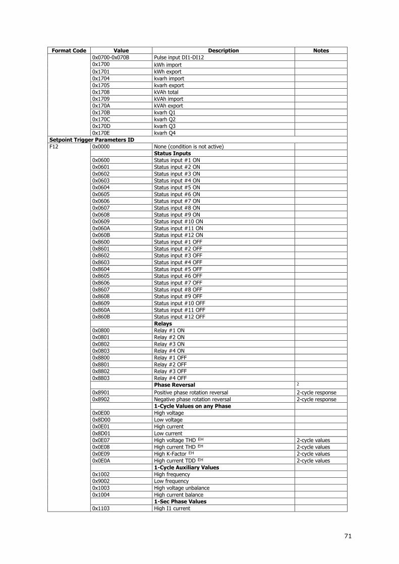
71
Format Code Value Description Notes
0x0700-0x070B Pulse input DI1-DI12
0x1700 kWh import
0x1701 kWh export
0x1704 kvarh import
0x1705 kvarh export
0x1708 kVAh total
0x1709 kVAh import
0x170A kVAh export
0x170B kvarh Q1
0x170C kvarh Q2
0x170D kvarh Q3
0x170E kvarh Q4
Setpoint Trigger Parameters ID
F12 0x0000 None (condition is not active)
Status Inputs
0x0600 Status input #1 ON
0x0601 Status input #2 ON
0x0602 Status input #3 ON
0x0603 Status input #4 ON
0x0604 Status input #5 ON
0x0605 Status input #6 ON
0x0606 Status input #7 ON
0x0607 Status input #8 ON
0x0608 Status input #9 ON
0x0609 Status input #10 ON
0x060A Status input #11 ON
0x060B Status input #12 ON
0x8600 Status input #1 OFF
0x8601 Status input #2 OFF
0x8602 Status input #3 OFF
0x8603 Status input #4 OFF
0x8604 Status input #5 OFF
0x8605 Status input #6 OFF
0x8606 Status input #7 OFF
0x8607 Status input #8 OFF
0x8608 Status input #9 OFF
0x8609 Status input #10 OFF
0x860A Status input #11 OFF
0x860B Status input #12 OFF
Relays
0x0800 Relay #1 ON
0x0801 Relay #2 ON
0x0802 Relay #3 ON
0x0803 Relay #4 ON
0x8800 Relay #1 OFF
0x8801 Relay #2 OFF
0x8802 Relay #3 OFF
0x8803 Relay #4 OFF
Phase Reversal 2
0x8901 Positive phase rotation reversal 2-cycle response
0x8902 Negative phase rotation reversal 2-cycle response
1-Cycle Values on any Phase
0x0E00 High voltage
0x8D00 Low voltage
0x0E01 High current
0x8D01 Low current
0x0E07 High voltage THD EH 2-cycle values
0x0E08 High current THD EH 2-cycle values
0x0E09 High K-Factor EH 2-cycle values
0x0E0A High current TDD EH 2-cycle values
1-Cycle Auxiliary Values
0x1002 High frequency
0x9002 Low frequency
0x1003 High voltage unbalance
0x1004 High current balance
1-Sec Phase Values
0x1103 High I1 current

72
Format Code Value Description Notes
0x1104 High I2 current
0x1105 High I3 current
0x9103 Low I1 current
0x9104 Low I2 current
0x9105 Low I3 current
1-Sec Values on any Phase
0x1300 High voltage
0x9200 Low voltage
0x1301 High current
0x9201 Low current
1-Sec Total Values
0x1406 High total kW import
0x1407 High total kW export
0x1408 High total kvar import
0x1409 High total kvar export
0x1402 High total kVA
0x9404 Low total PF Lag
0x9405 Low total PF Lead
1-Sec Auxiliary Values
0x1501 High neutral current
0x1502 High frequency
0x9502 Low frequency
Present Demands
0x1600 High V1/V12 Volt demand
0x1601 High V2/V23 Volt demand
0x1602 High V3/V31 Volt demand
0x1603 High I1 Ampere demand
0x1604 High I2 Ampere demand
0x1605 High I3 Ampere demand
0x1606 High block kW import demand E
0x1608 High block kVA demand E
0x1609 High sliding window kW import demand E
0x160B High sliding window kVA demand E
0x160F High accumulated kW import demand E
0x1611 High accumulated kVA demand E
0x1612 High predicted kW import demand E
0x1614 High predicted kVA demand E
Time and Date Parameters
0x0B02 Day of week
0x0B03 Year
0x0B04 Month
0x0B05 Day of month
0x0B06 Hour
0x0B07 Minutes
0x0B08 Seconds
0x0B09 Minute interval (1,2,3,4,5,10,15,20,30,60 min)
Setpoint Action ID
F14 0x0000 No action
0x3000 Operate Relay #1
0x3001 Operate Relay #2
0x3002 Operate Relay #3
0x3003 Operate Relay #4
0x3100 Release latched Relay #1
0x3101 Release latched Relay #2
0x3102 Release latched Relay #3
0x3103 Release latched Relay #4
0x4000 Increment counter #1
0x4001 Increment counter #2
0x4002 Increment counter #3
0x4003 Increment counter #4
0x4400 Count operating time using counter #1
0x4401 Count operating time using counter #2
0x4402 Count operating time using counter #3
0x4403 Count operating time using counter #4
0x5100 Send event notification
0x7100 Data log #1
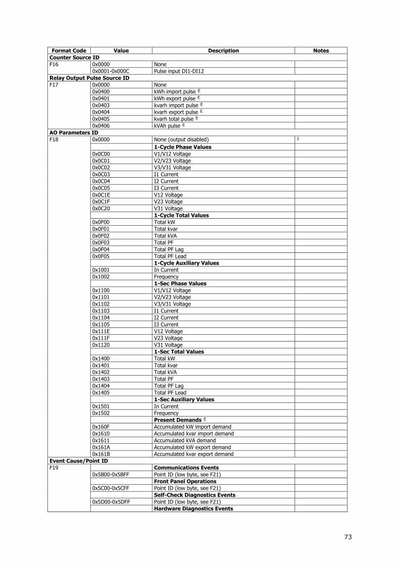
73
Format Code Value Description Notes
Counter Source ID
F16 0x0000 None
0x0001-0x000C Pulse input DI1-DI12
Relay Output Pulse Source ID
F17 0x0000 None
0x0400 kWh import pulse E
0x0401 kWh export pulse E
0x0403 kvarh import pulse E
0x0404 kvarh export pulse E
0x0405 kvarh total pulse E
0x0406 kVAh pulse E
AO Parameters ID
F18 0x0000 None (output disabled) 2
1-Cycle Phase Values
0x0C00 V1/V12 Voltage
0x0C01 V2/V23 Voltage
0x0C02 V3/V31 Voltage
0x0C03 I1 Current
0x0C04 I2 Current
0x0C05 I3 Current
0x0C1E V12 Voltage
0x0C1F V23 Voltage
0x0C20 V31 Voltage
1-Cycle Total Values
0x0F00 Total kW
0x0F01 Total kvar
0x0F02 Total kVA
0x0F03 Total PF
0x0F04 Total PF Lag
0x0F05 Total PF Lead
1-Cycle Auxiliary Values
0x1001 In Current
0x1002 Frequency
1-Sec Phase Values
0x1100 V1/V12 Voltage
0x1101 V2/V23 Voltage
0x1102 V3/V31 Voltage
0x1103 I1 Current
0x1104 I2 Current
0x1105 I3 Current
0x111E V12 Voltage
0x111F V23 Voltage
0x1120 V31 Voltage
1-Sec Total Values
0x1400 Total kW
0x1401 Total kvar
0x1402 Total kVA
0x1403 Total PF
0x1404 Total PF Lag
0x1405 Total PF Lead
1-Sec Auxiliary Values
0x1501 In Current
0x1502 Frequency
Present Demands E
0x160F Accumulated kW import demand
0x1610 Accumulated kvar import demand
0x1611 Accumulated kVA demand
0x161A Accumulated kW export demand
0x161B Accumulated kvar export demand
Event Cause/Point ID
F19 Communications Events
0x5B00-0x5BFF Point ID (low byte, see F21)
Front Panel Operations
0x5C00-0x5CFF Point ID (low byte, see F21)
Self-Check Diagnostics Events
0x5D00-0x5DFF Point ID (low byte, see F21)
Hardware Diagnostics Events

74
Format Code Value Description Notes
0x6202 RAM/Data error
0x6203 Hardware watchdog reset
0x6204 Sampling fault
0x6205 CPU exception
0x6206 Reserved
0x6207 Software watchdog reset
0x620D Low battery
0x620F EEPROM fault
External Events
0x6300 Power down
0x6308 Power up
0x6309 External reset
Event Effect ID
F20 Communications/Self-check/Front Panel Events
0x0000 None
0x6000 Total energy registers cleared
0x6100 All total maximum demands cleared
0x6101 Power maximum demands cleared
0x6102 Volt/Ampere maximum demands cleared
0x6200 Summary/TOU energy registers cleared
0x6300 Summary/TOU maximum demand registers cleared
0x6400 All counters cleared
0x6401-0x6403 Counter cleared (low byte = counter ID)
0x6500 Min/Max log cleared
0x6A00-0x6A1A Log file cleared (low byte = File ID)
0x6B06 Communication counters cleared
0xF100-0xF10F Setpoint cleared (low byte = setpoint ID)
0xF200 Setup/Data cleared
0xF300 Setup reset (set by default)
0xF400 Setup changed
0xF500 RTC set
Data Point ID
F21 Data Locations
0x03 Data memory
0x04 Factory setup
0x05 Access/Password setup
0x06 Basic setup
0x07 Communications setup
0x08 Real-time clock 4
0x09 Digital inputs setup
0x0A Pulse counters setup
0x0B AO setup
0x0E Timers setup
0x10 Event/alarm setpoints
0x11 Pulsing setup
0x12 User assignable register map
0x14 Data log setup
0x15 File/Memory setup
0x16 TOU energy registers setup
0x18 TOU daily profiles
0x19 TOU calendar
0x1B RO Setup
0x1C User selectable options
0x1F DNP 3.0 class 0 map
0x20 DNP 3.0 options setup
0x21 DNP 3.0 events setup
0x22 DNP 3.0 event setpoints
0x23 Calibration registers
0x24 Date/Time Setup
0x25 Net setup
Event Type ID
F22 Setpoint Events
0x0000 SP: Generic setpoint event
0x0001-0x0010 SP1-SP16: Setpoint #1-#16 event
Device Diagnostics
F23 Reg. 3475 - Bit 0 Reserved
Reg. 3475 - Bit 1 Reserved

75
Format Code Value Description Notes
Reg. 3475 - Bit 2 = 1 RAM/Data error
Reg. 3475 - Bit 3 = 1 CPU watchdog reset
Reg. 3475 - Bit 4 = 1 Sampling fault
Reg. 3475 - Bit 5 = 1 CPU exception
Reg. 3475 - Bit 6 Reserved
Reg. 3475 - Bit 7 = 1 Software watchdog reset
Reg. 3475 - Bit 8 = 1 Power down
Reg. 3475 - Bit 9 = 1 Device reset
Reg. 3475 - Bit 10 = 1 Configuration reset
Reg. 3475 - Bit 11 = 1 RTC fault
Reg. 3475 - Bit 12 Reserved
Reg. 3475 - Bit 13 Reserved
Reg. 3475 - Bit 14 Reserved
Reg. 3475 - Bit 15 = 1 EEPROM fault
Reg. 3476 – Bit 0 Reserved
Reg. 3476 – Bit 1 Reserved
Reg. 3476 – Bit 2 Reserved
Reg. 3476 – Bit 3 Correct wiring configuration verification:
DNP Object Variations
F24
Static Binary Input Objects
0 Single-Bit Binary Input
1 Binary Input With Status
Static Binary Counters
0 32-bit Binary Counter
1 32-bit Binary Counter Without Flag
2 16-bit Binary Counter
3 16-bit Binary Counter Without Flag
Frozen Binary Counters
0 32-bit Frozen Counter
1 32-bit Frozen Counter Without Flag
2 32-bit Frozen Counter With Time of Freeze
3 16-bit Frozen Counter
4 16-bit Frozen Counter Without Flag
5 16-bit Frozen Counter With Time of Freeze
Static Analog Input Objects
0 32-bit Analog Input
1 32-bit Analog Input Without Flag
2 16-bit Analog Input
3 16-bit Analog Input Without Flag
DNP Class 0 Objects
F25 0x1E01 Analog Input 30:01
0x1E02 Analog Input 30:02
0x1E03 Analog Input 30:03
0x1E04 Analog Input 30:04
0x1F01 Frozen Analog Input 31:01
0x1F02 Frozen Analog Input 31:02
0x1F03 Frozen Analog Input 31:03
0x1F04 Frozen Analog Input 31:04
0x1F05 Frozen Analog Input 31:05
0x1F06 Frozen Analog Input 31:06
0x2801 Analog Output 40:01
0x2802 Analog Output 40:02
0x0101 Binary Input 01:01
0x0102 Binary Input 01:02
0x0A01 Binary Output 10:01
0x0A02 Binary Output Status 10:02
0x1401 Binary Counter 20:01
0x1402 Binary Counter 20:02
0x1405 Binary Counter 20:05
0x1406 Binary Counter 20:06
0x1501 Frozen Counter 21:01
0x1502 Frozen Counter 21:02
0x1505 Frozen Counter 21:05
0x1506 Frozen Counter 21:06
0x1509 Frozen Counter 21:09
0x150A Frozen Counter 21:10
0x3201 Time and Date 50:01

76
Format Code Value Description Notes
Wiring Mode
F26 0 3OP2 - 3-wire open delta using 2 CTs (2 element)
1 4LN3 - 4-wire WYE using 3 PTs (3 element), line-to-neutral voltage readings
2 3DIR2 - 3-wire direct connection using 2 CTs (2 element)
3 4LL3 - 4-wire WYE using 3 PTs (3 element), line-to-line voltage readings
4 3OP3 - 3-wire open delta using 3 CTs (2 1/2 element)
5 3LN3 - 4-wire WYE using 2 PTs (2 1/2 element), line-to-neutral voltage readings
6 3LL3 - 4-wire WYE using 2 PTs (2 1/2 element), line-to-line voltage readings
7 2LL1 – 2-wire connection using the current from one phase (1 CT) and the L-L voltage from the other two phases
8 3BLN3 - 3-wire broken delta using 2 PTs (2 1/2 element), line-to-neutral voltage readings
9 3BLL3 - 3-wire broken delta using 2 PTs (2 1/2 element), line-to-line voltage readings
15 1LL3 - 2-wire connection using the current from the same phase of three separate branches (3 CT) and the L-L voltage from the other two phases (1 PT)
Instrument Options
F28 Bit 0=1 120V Option
Bit 1=1 690V Option
Bits 2-5 Reserved
Bit 6=1 Analog output 0/4 or 4/20mA
Bit 7=1 Analog output 0-1mA
Bit 8=1 Analog output ±1mA
Bit 9=1 RO option
Bit 10=1 DI option
Bit 11=1 Reserved
Bit 12=1 Setup is secured by a password (authorization required)
Bits 13-15 Reserved
Bits 16-18 Number of RO - 1
Bits 19-22 Number of DI – 1
Bits 23-24 Number of AO - 1
Bits 25-31 Reserved
I/O Slot Types
F29 DI DRY 00000000B
RO 00100000B
AI ±1 mA 01010000B
AI 0-20 mA 01010001B
AI 4-20 mA 01010010B
AI 0-1 mA 01010011B
AO ±1 mA 01100000B
AO 0-20 mA 01100001B
AO 4-20 mA 01100010B
AO 0-1 mA 01100011B
Empty slot 11111111B
NOTES: 1 Analog Outputs
1) For bi-directional analog output (1 mA), the zero scale setup corresponds to the center (0 mA) of the scale range, and the direction of the current matches the sign of the output parameter. Unsigned parameters are output within the current range 0 to +1 mA and can be scaled as in the case of single-ended analog output (0-1 mA).
For signed values, such as powers and signed power factor, the scale is always symmetrical with regard to 0 mA, and the full scale corresponds to +1 mA output for positive readings and to -1 mA output for negative readings. The zero scale (0 mA output) is permanently set in the instrument to zero for all parameters except the signed power factor for which it is set to 1.000 (see Note 2). In write requests, the zero scale is ignored.
2) Except for the signed power factor, the setup scale is continuous within the entire value range. For signed power factor, the setup scale is broken at +1.000 in order to provide continuous output current when the power factor changes close to 1.000. The setup scale is symmetrical in the range of -0 to +0 with a center at 1.000 (-1.000 is assumed to be equal to +1.000). Negative power factor is output as -1.000 minus measured value, and non-negative power factor is output as +1.000 minus measured value. To set the entire range for power factor from-0 to +0, the scales would be specified as -0 to 0. Because of the

77
fact that negative zero may not be transmitted through communications, the value of -0.001 is used to specify the scale of -0, and both +0.001 and 0.000 are used to specify the scale of +0.
2 Phase Reversal Trigger The setpoint is operated when the actual phase sequence does not match the designated phase rotation order.
3 In 3OP2 and 3OP3 wiring modes, the voltage waveforms represent line-to-line voltages; in any other wiring mode, they will be line-to-neutral voltages.
4 The event value field shows the present meter time in the F1 format.


