R Series RBX "ANTI - SHOCK" AIR RELEASE & VACUUM BREAK VALVES CONTENT PAGE CATALOGUE INDEX OPERATION -SERIES RBX 1-2 RECOMMENDED INSTALLATION ARRANGEMENTS -SERIES RBX 3 COMPONENT DESCRIPTION & MATERIAL SPECIFICATIONS - SERIES RBX 4 DN25(1") & DN50(2") - Screwed COMPONENT DESCRIPTION & MATERIAL SPECIFICATIONS - SERIES RBX 5 DN80(3") & DN100(4") - Flanged COMPONENT DESCRIPTION & MATERIAL SPECIFICATIONS - SERIES RBX 6 DN150(6") & DN200(8") - Flanged COMPONENT DESCRIPTION & MATERIAL SPECIFICATIONS - SERIES RBX 7 DN25(1") & DN50(2") - Screwed GENERAL SPECIFICATIONS - SERIES RBX 8 DN80(3") & DN100(4") - Flanged GENERAL SPECIFICATIONS - SERIES RBX 9 DN150(6") & DN200(8") - Flanged SELECTION & POSITIONING - SERIES RBX 10-12 SURGE & WATERHAMMER PROTECTION SERIES RBX 13-14 SMALL ORIFICE DISCHARGE PERFORMANCE 15 WHY VENT -O- MAT SERIES RBX ? 16 PURCHASE SPECIFICATIONS - SERIES RBX 17 ORDERING GUIDE & TEST SPECIFICATIONS - SERIES RBX 18 OPERATION - SERIES RBXb 19-20 RECOMMENDED INSTALLATION ARRANGEMENTS - SERIES RBXb 21 COMPONENT DESCRIPTION & MATERIAL SPECIFICATIONS - SERIES RBXb 22 DN25(1") & DN50(2") - Screwed COMPONENT DESCRIPTION & MATERIAL SPECIFICATIONS - SERIES RBXb 23 DN80(3 & DN100(4") - Flanged COMPONENT DESCRIPTION & MATERIAL SPECIFICATIONS - SERIES RBXb 24 DN150(6") & DN200(8") - Flanged COMPONENT DESCRIPTION & MATERIAL SPECIFICATIONS - SERIES RBXb 25 DN25(1") & DN50(2") - Screwed GENERAL SPECIFICATIONS - SERIES RBXb 26 DN80(3 & DN100(4") - Flanged GENERAL SPECIFICATIONS - SERIES RBXb 27 DN150(6") & DN200(8") - Flanged PURCHASE SPECIFICATIONS - SERIES RBXb 28 OPERATION - SERIES RBXv 29-30 COMPONENT DESCRIPTION & MATERIAL SPECIFICATIONS - SERIES RBXv 31 DN50(1") & DN50(2") - Screwed COMPONENT DESCRIPTION & MATERIAL SPECIFICATIONS - SERIES RBXv 32 DN80(3") & DN100(4") - Screwed COMPONENT DESCRIPTION & MATERIAL SPECIFICATIONS - SERIES RBXv 33 DN150(6") & DN200(8") - Screwed 34 DN25(1") & DN50(2 - Screwed GENERAL SPECIFICATIONS - SERIES RBXv 35 DN80(3 & DN100(4 - Flanged GENERAL SPECIFICATIONS - SERIES RBXv 36 DN150(6 & DN200(8 - Flanged PURCHASE SPECIFICATIONS - SERIES RBXv 37 ORDERING GUIDE - SERIES RBXb & RBXv 38 ") ") GENERAL SPECIFICATIONS - SERIES RBXv ") ") ") ") ")
Transcript
R
Series RBX"ANTI - SHOCK"
AIR RELEASE & VACUUM BREAK VALVES
CONTENT PAGE
CATALOGUE INDEX
OPERATION -SERIES RBX 1-2RECOMMENDED INSTALLATION ARRANGEMENTS -SERIES RBX 3COMPONENT DESCRIPTION & MATERIAL SPECIFICATIONS - SERIES RBX 4DN25(1") & DN50(2") - ScrewedCOMPONENT DESCRIPTION & MATERIAL SPECIFICATIONS - SERIES RBX 5DN80(3") & DN100(4") - Flanged COMPONENT DESCRIPTION & MATERIAL SPECIFICATIONS - SERIES RBX 6DN150(6") & DN200(8") - FlangedCOMPONENT DESCRIPTION & MATERIAL SPECIFICATIONS - SERIES RBX 7DN25(1") & DN50(2") - ScrewedGENERAL SPECIFICATIONS - SERIES RBX 8DN80(3") & DN100(4") - FlangedGENERAL SPECIFICATIONS - SERIES RBX 9DN150(6") & DN200(8") - Flanged SELECTION & POSITIONING - SERIES RBX 10-12SURGE & WATERHAMMER PROTECTION SERIES RBX 13-14SMALL ORIFICE DISCHARGE PERFORMANCE 15WHY VENT -O- MAT SERIES RBX ? 16PURCHASE SPECIFICATIONS - SERIES RBX 17ORDERING GUIDE & TEST SPECIFICATIONS - SERIES RBX 18OPERATION - SERIES RBXb 19-20RECOMMENDED INSTALLATION ARRANGEMENTS - SERIES RBXb 21COMPONENT DESCRIPTION & MATERIAL SPECIFICATIONS - SERIES RBXb 22DN25(1") & DN50(2") - ScrewedCOMPONENT DESCRIPTION & MATERIAL SPECIFICATIONS - SERIES RBXb 23DN80(3 & DN100(4") - Flanged COMPONENT DESCRIPTION & MATERIAL SPECIFICATIONS - SERIES RBXb 24DN150(6") & DN200(8") - FlangedCOMPONENT DESCRIPTION & MATERIAL SPECIFICATIONS - SERIES RBXb 25DN25(1") & DN50(2") - ScrewedGENERAL SPECIFICATIONS - SERIES RBXb 26DN80(3 & DN100(4") - FlangedGENERAL SPECIFICATIONS - SERIES RBXb 27DN150(6") & DN200(8") - FlangedPURCHASE SPECIFICATIONS - SERIES RBXb 28OPERATION - SERIES RBXv 29-30COMPONENT DESCRIPTION & MATERIAL SPECIFICATIONS - SERIES RBXv 31DN50(1") & DN50(2") - ScrewedCOMPONENT DESCRIPTION & MATERIAL SPECIFICATIONS - SERIES RBXv 32DN80(3") & DN100(4") - ScrewedCOMPONENT DESCRIPTION & MATERIAL SPECIFICATIONS - SERIES RBXv 33DN150(6") & DN200(8") - Screwed
34DN25(1") & DN50(2 - ScrewedGENERAL SPECIFICATIONS - SERIES RBXv 35DN80(3 & DN100(4 - FlangedGENERAL SPECIFICATIONS - SERIES RBXv 36DN150(6 & DN200(8 - FlangedPURCHASE SPECIFICATIONS - SERIES RBXv 37ORDERING GUIDE - SERIES RBXb & RBXv 38
")
")
GENERAL SPECIFICATIONS - SERIES RBXv ")
") ")
") ")
R
Series RBX
OPERATION
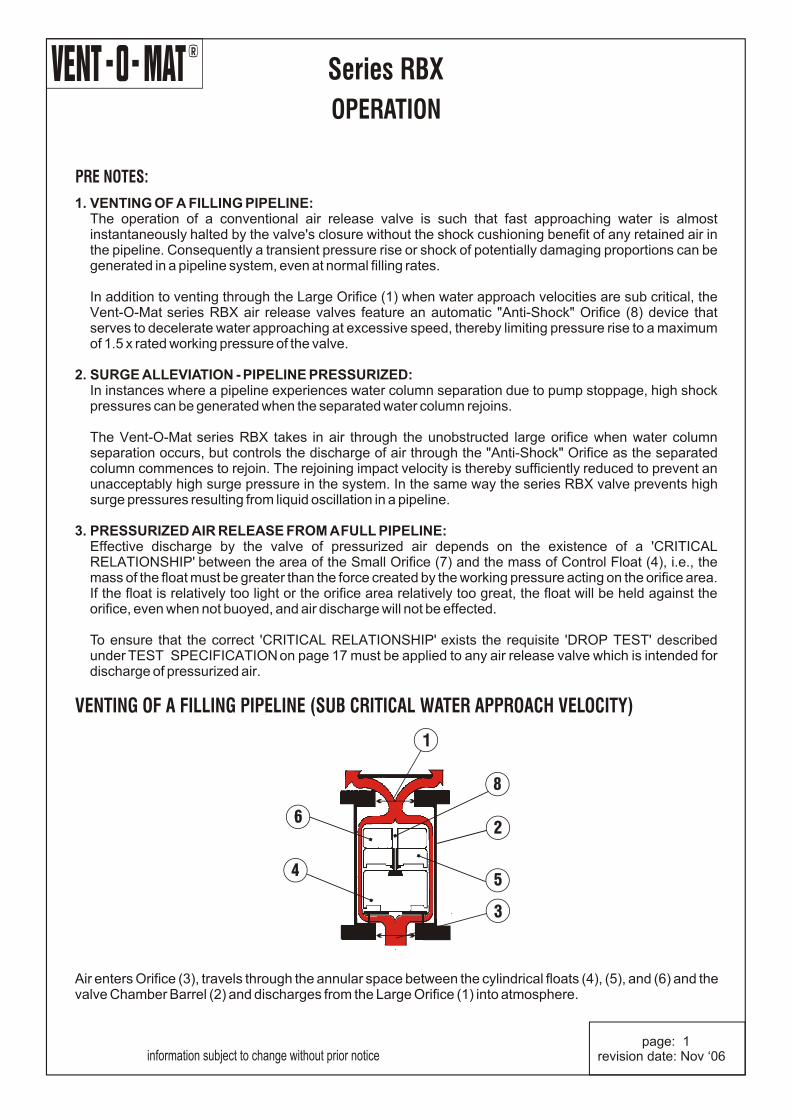
1. VENTING OF A FILLING PIPELINE:The operation of a conventional air release valve is such that fast approaching water is almost instantaneously halted by the valve's closure without the shock cushioning benefit of any retained air in the pipeline. Consequently a transient pressure rise or shock of potentially damaging proportions can be generated in a pipeline system, even at normal filling rates.
In addition to venting through the Large Orifice (1) when water approach velocities are sub critical, the Vent-O-Mat series RBX air release valves feature an automatic "Anti-Shock" Orifice (8) device that serves to decelerate water approaching at excessive speed, thereby limiting pressure rise to a maximum of 1.5 x rated working pressure of the valve.
2. SURGE ALLEVIATION - PIPELINE PRESSURIZED:In instances where a pipeline experiences water column separation due to pump stoppage, high shock pressures can be generated when the separated water column rejoins.
The Vent-O-Mat series RBX takes in air through the unobstructed large orifice when water column separation occurs, but controls the discharge of air through the "Anti-Shock" Orifice as the separated column commences to rejoin. The rejoining impact velocity is thereby sufficiently reduced to prevent an unacceptably high surge pressure in the system. In the same way the series RBX valve prevents high surge pressures resulting from liquid oscillation in a pipeline.
3. PRESSURIZED AIR RELEASE FROM A FULL PIPELINE:Effective discharge by the valve of pressurized air depends on the existence of a 'CRITICAL RELATIONSHIP' between the area of the Small Orifice (7) and the mass of Control Float (4), i.e., the mass of the float must be greater than the force created by the working pressure acting on the orifice area. If the float is relatively too light or the orifice area relatively too great, the float will be held against the orifice, even when not buoyed, and air discharge will not be effected.
To ensure that the correct 'CRITICAL RELATIONSHIP' exists the requisite 'DROP TEST' described under TEST SPECIFICATION on page 17 must be applied to any air release valve which is intended for discharge of pressurized air.
PRE NOTES:
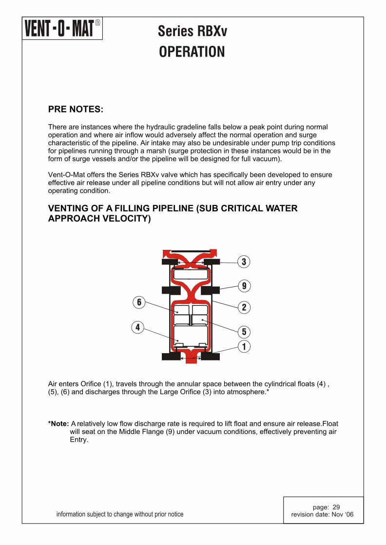
VENTING OF A FILLING PIPELINE (SUB CRITICAL WATER APPROACH VELOCITY)
Air enters Orifice (3), travels through the annular space between the cylindrical floats (4), (5), and (6) and the valve Chamber Barrel (2) and discharges from the Large Orifice (1) into atmosphere.
information subject to change without prior notice page: 1revision date: Nov ‘06
R
Series RBX
OPERATION
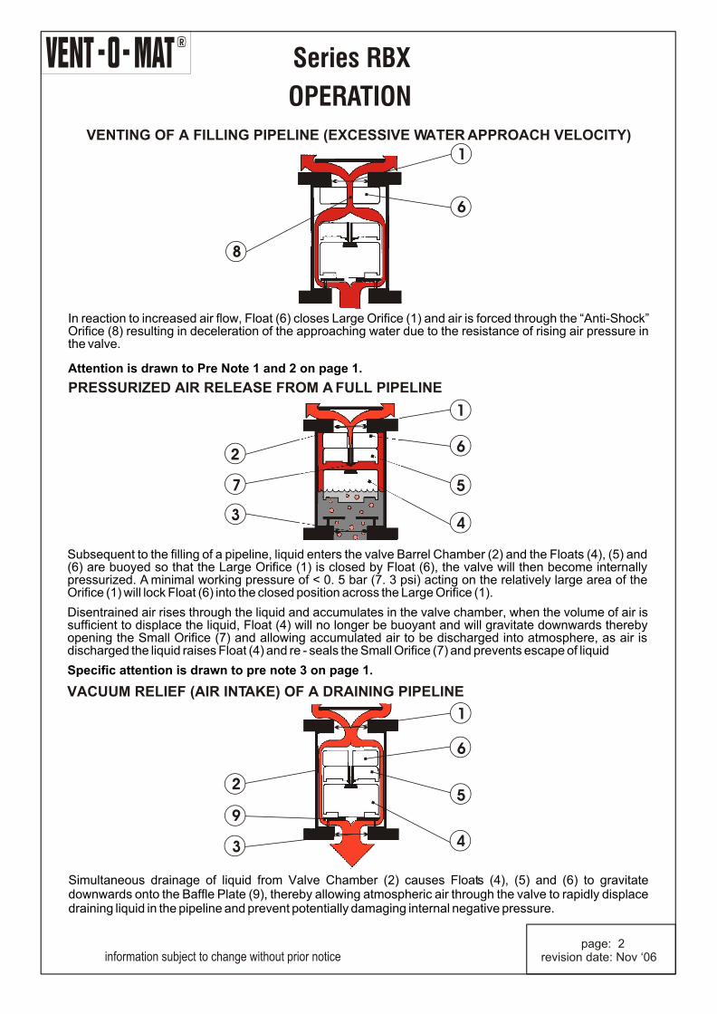
VENTING OF A FILLING PIPELINE (EXCESSIVE WATER APPROACH VELOCITY)
PRESSURIZED AIR RELEASE FROM A FULL PIPELINE
VACUUM RELIEF (AIR INTAKE) OF A DRAINING PIPELINE
1
6
8
2
9
3 4
5
6
1
1
6
5
43
7
2
In reaction to increased air flow, Float (6) closes Large Orifice (1) and air is forced through the “Anti-Shock” Orifice (8) resulting in deceleration of the approaching water due to the resistance of rising air pressure in the valve. Attention is drawn to Pre Note 1 and 2 on page 1.
Subsequent to the filling of a pipeline, liquid enters the valve Barrel Chamber (2) and the Floats (4), (5) and (6) are buoyed so that the Large Orifice (1) is closed by Float (6), the valve will then become internally pressurized. A minimal working pressure of < 0. 5 bar (7. 3 psi) acting on the relatively large area of the Orifice (1) will lock Float (6) into the closed position across the Large Orifice (1). Disentrained air rises through the liquid and accumulates in the valve chamber, when the volume of air is sufficient to displace the liquid, Float (4) will no longer be buoyant and will gravitate downwards thereby opening the Small Orifice (7) and allowing accumulated air to be discharged into atmosphere, as air is discharged the liquid raises Float (4) and re - seals the Small Orifice (7) and prevents escape of liquid Specific attention is drawn to pre note 3 on page 1.
Simultaneous drainage of liquid from Valve Chamber (2) causes Floats (4), (5) and (6) to gravitate downwards onto the Baffle Plate (9), thereby allowing atmospheric air through the valve to rapidly displace draining liquid in the pipeline and prevent potentially damaging internal negative pressure.
information subject to change without prior notice page: 2revision date: Nov ‘06
R
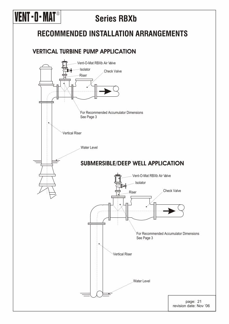
RECOMMENDED INSTALLATION ARRANGEMENTS
Series RBX
information subject to change without prior notice page: 3revision date: Nov ‘06
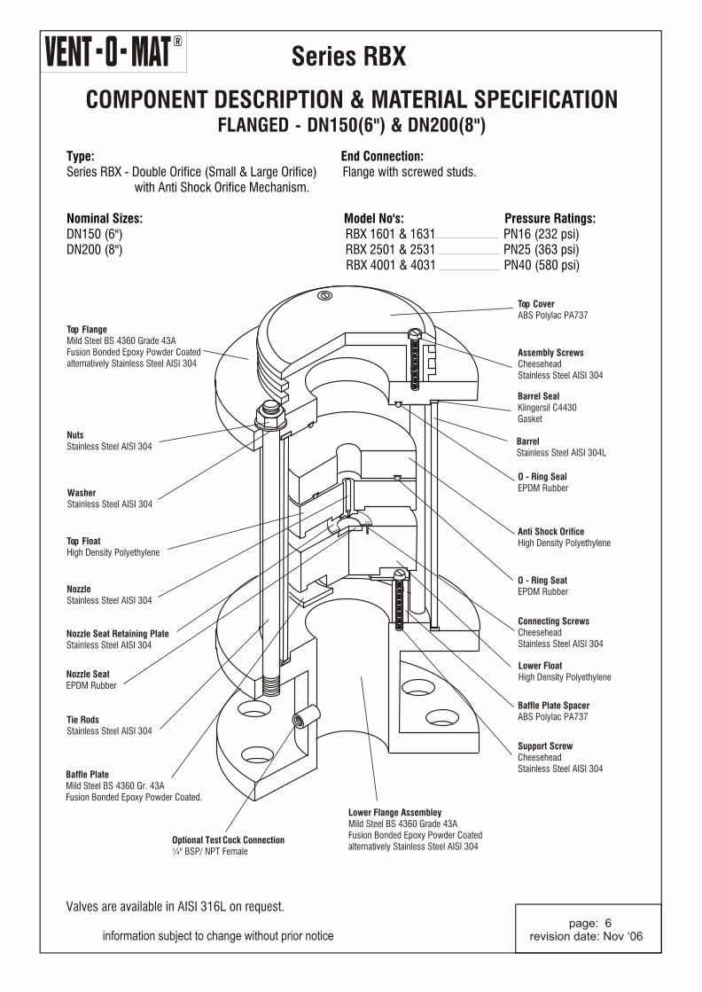
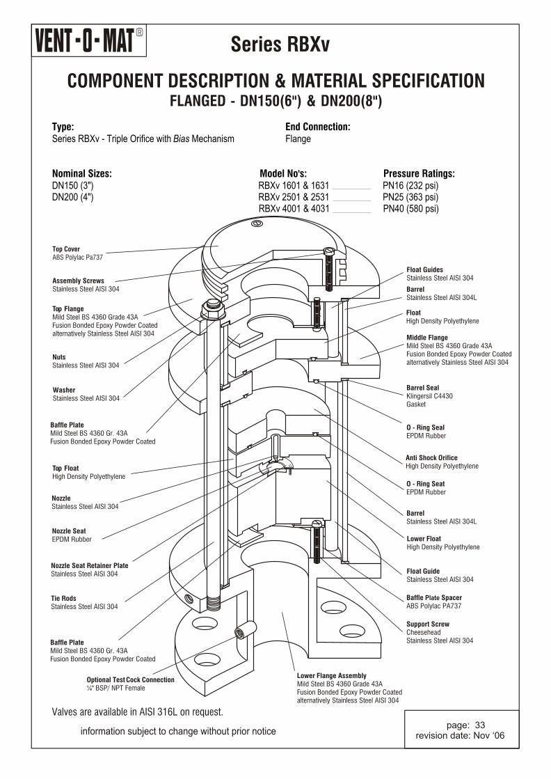
COMPONENT DESCRIPTION & MATERIAL SPECIFICATIONFLANGED - DN150(6") & DN200(8")
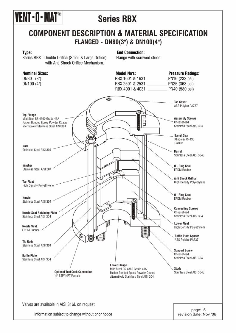
BarrelStainless Steel AISI 304L
Series RBX
Type: End Connection:Series RBX - Double Orifice (Small & Large Orifice) Flange with screwed studs. with Anti Shock Orifice Mechanism. Nominal Sizes: Model No's: Pressure Ratings: DN150 (6") RBX 1601 & 1631 PN16 (232 psi)DN200 (8") RBX 2501 & 2531 PN25 (363 psi) RBX 4001 & 4031 PN40 (580 psi)
information subject to change without prior notice page: 6revision date: Nov ‘06
Barrel SealKlingersil C4430 Gasket
Valves are available in AISI 316L on request.
Optional Test Cock Connection¼" BSP/ NPT Female
R
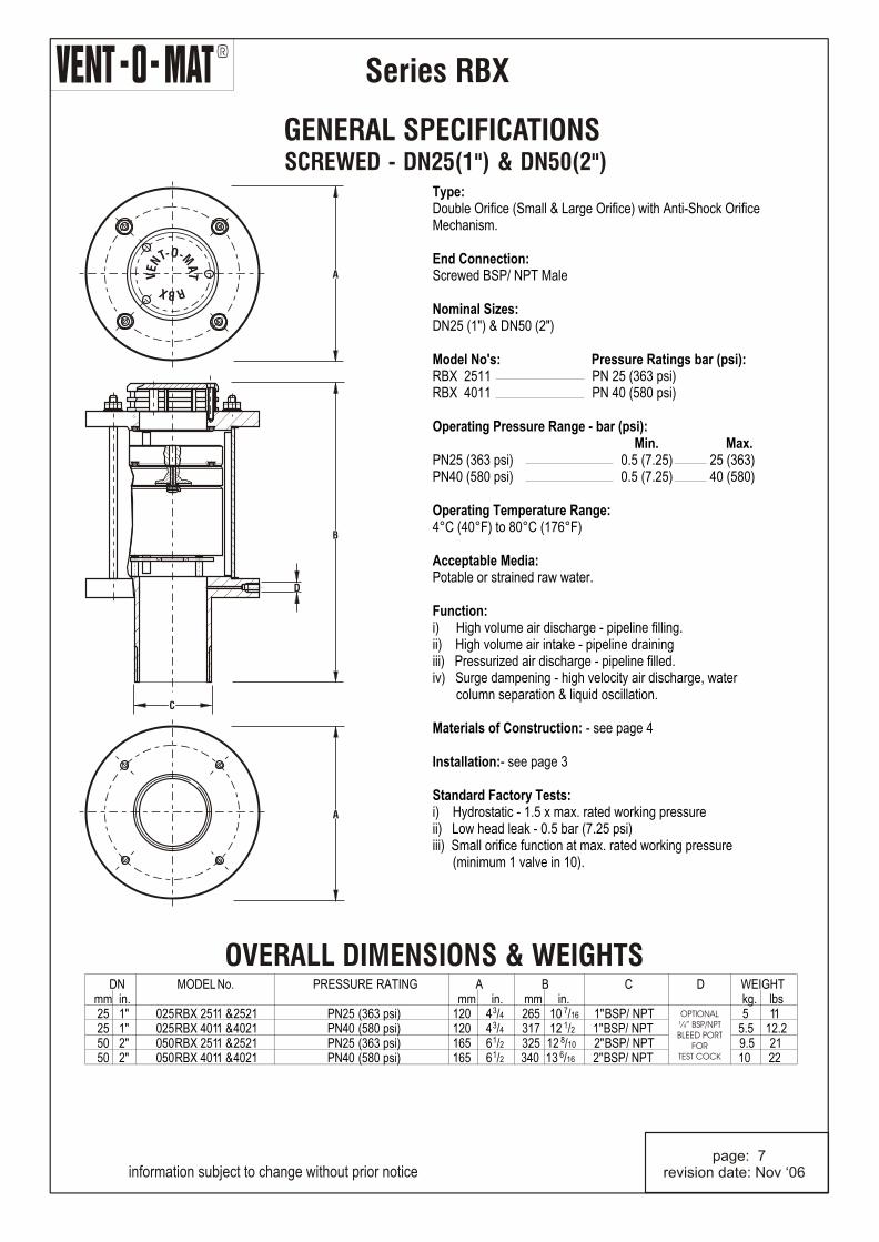
GENERAL SPECIFICATIONS SCREWED - DN25(1") & DN50(2")
Series RBX
information subject to change without prior notice page: 7revision date: Nov ‘06
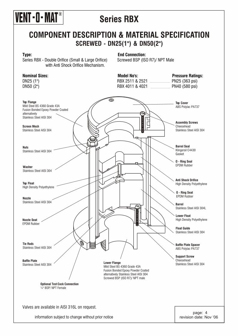
Type:Double Orifice (Small & Large Orifice) with Anti-Shock Orifice Mechanism. End Connection:Screwed BSP/ NPT Male Nominal Sizes:DN25 (1") & DN50 (2") Model No's: Pressure Ratings bar (psi):RBX 2511 PN 25 (363 psi) RBX 4011 PN 40 (580 psi) Operating Pressure Range - bar (psi): Min. Max.PN25 (363 psi) 0.5 (7.25) 25 (363)PN40 (580 psi) 0.5 (7.25) 40 (580) Operating Temperature Range:4°C (40°F) to 80°C (176°F) Acceptable Media:Potable or strained raw water. Function:i) High volume air discharge - pipeline filling.ii) High volume air intake - pipeline drainingiii) Pressurized air discharge - pipeline filled.iv) Surge dampening - high velocity air discharge, water column separation & liquid oscillation.
Materials of Construction: - see page 4
Installation:- see page 3 Standard Factory Tests:i) Hydrostatic - 1.5 x max. rated working pressureii) Low head leak - 0.5 bar (7.25 psi)iii) Small orifice function at max. rated working pressure (minimum 1 valve in 10).
OVERALL DIMENSIONS & WEIGHTS
O- -MTN AE T
V
RXB
D
B
C
A
A
DN MODEL No. PRESSURE RATING A B C D WEIGHT mm in. mm in. mm in. kg. lbs
Type:Double Orifice (Small & Large Orifice) with Anti-Shock Orifice Mechanism.
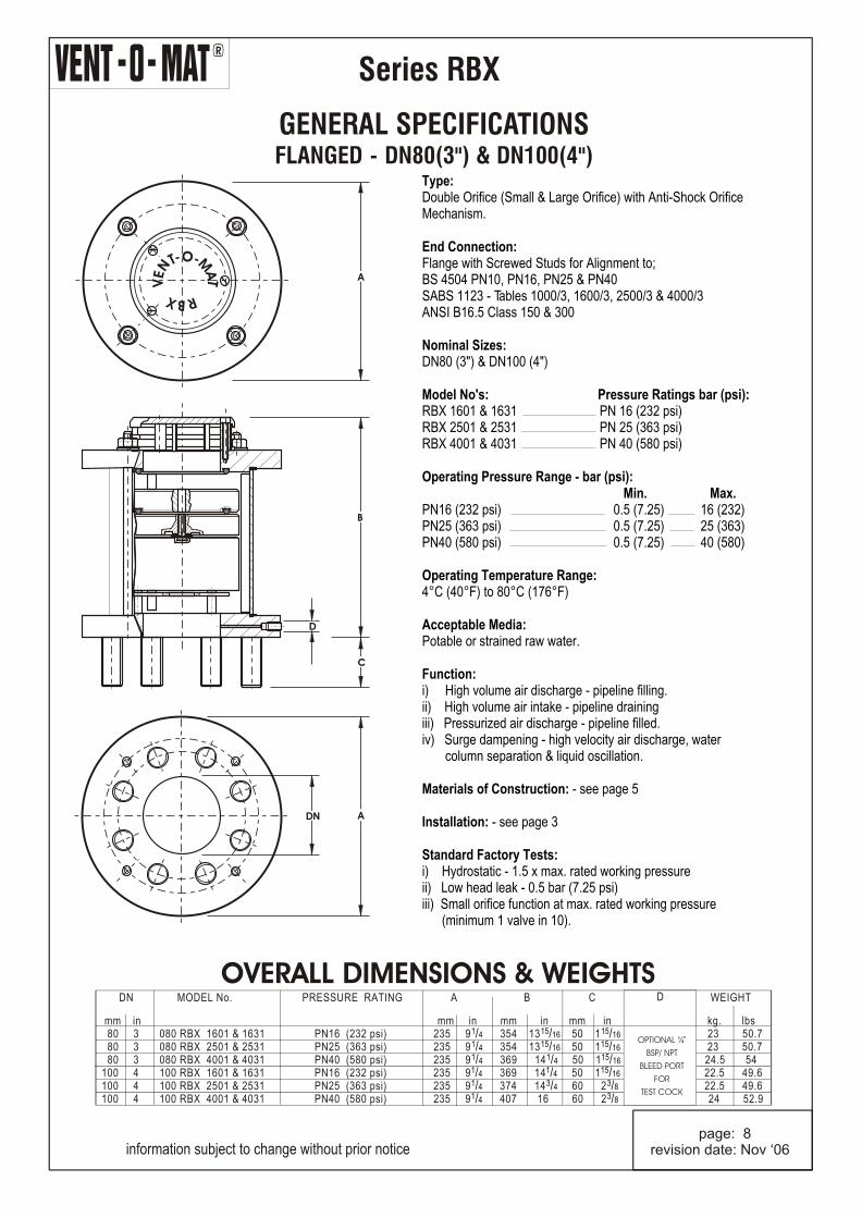
End Connection:Flange with Screwed Studs for Alignment to;BS 4504 PN10, PN16, PN25 & PN40SABS 1123 - Tables 1000/3, 1600/3, 2500/3 & 4000/3ANSI B16.5 Class 150 & 300 Nominal Sizes:DN80 (3") & DN100 (4") Model No's: Pressure Ratings bar (psi):RBX 1601 & 1631 PN 16 (232 psi) RBX 2501 & 2531 PN 25 (363 psi) RBX 4001 & 4031 PN 40 (580 psi) Operating Pressure Range - bar (psi): Min. Max.
PN25 (363 psi) 0.5 (7.25) 25 (363)PN40 (580 psi) 0.5 (7.25) 40 (580) Operating Temperature Range:4°C (40°F) to 80°C (176°F) Acceptable Media:Potable or strained raw water. Function:i) High volume air discharge - pipeline filling.ii) High volume air intake - pipeline drainingiii) Pressurized air discharge - pipeline filled.iv) Surge dampening - high velocity air discharge, water column separation & liquid oscillation.
Materials of Construction: - see page 5
Installation: - see page 3
Standard Factory Tests:i) Hydrostatic - 1.5 x max. rated working pressureii) Low head leak - 0.5 bar (7.25 psi)iii) Small orifice function at max. rated working pressure (minimum 1 valve in 10).
PN16 (232 psi) 0.5 (7.25) 16 (232)
OVERALL DIMENSIONS & WEIGHTS DN MODEL No. PRESSURE RATING A B C WEIGHT
information subject to change without prior notice page: 8revision date: Nov ‘06
O- -MTN AE T
V
RXB
A
B
C
D
DN A
R
Series RBX
GENERAL SPECIFICATIONS
Type:Double Orifice (Small & Large Orifice) with Anti-Shock Orifice Mechanism.
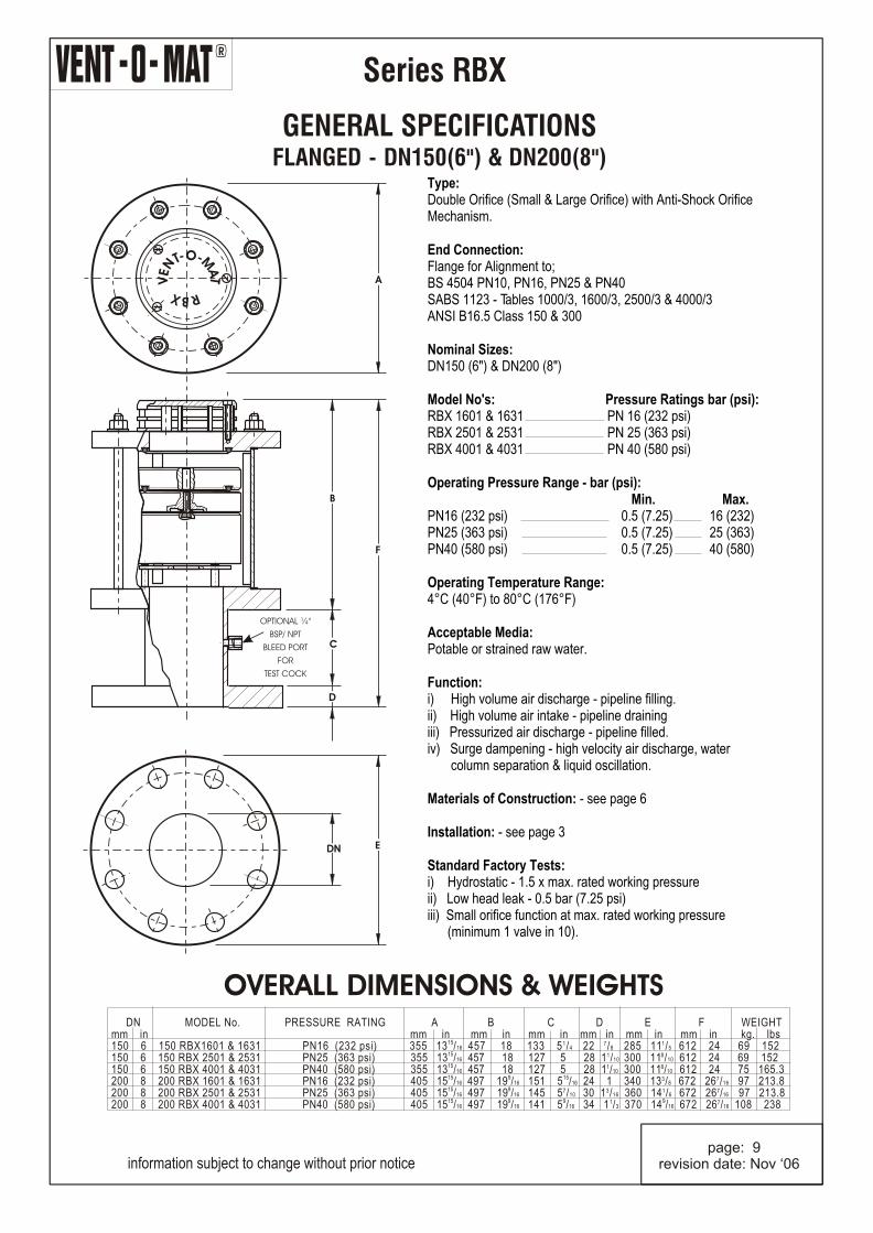
End Connection:Flange for Alignment to;BS 4504 PN10, PN16, PN25 & PN40SABS 1123 - Tables 1000/3, 1600/3, 2500/3 & 4000/3ANSI B16.5 Class 150 & 300 Nominal Sizes:DN150 (6") & DN200 (8") Model No's: Pressure Ratings bar (psi):RBX 1601 & 1631 PN 16 (232 psi)RBX 2501 & 2531 PN 25 (363 psi)RBX 4001 & 4031 PN 40 (580 psi) Operating Pressure Range - bar (psi): Min. Max.
PN25 (363 psi) 0.5 (7.25) 25 (363)PN40 (580 psi) 0.5 (7.25) 40 (580) Operating Temperature Range:4°C (40°F) to 80°C (176°F) Acceptable Media:Potable or strained raw water. Function:i) High volume air discharge - pipeline filling.ii) High volume air intake - pipeline drainingiii) Pressurized air discharge - pipeline filled.iv) Surge dampening - high velocity air discharge, water column separation & liquid oscillation.
Materials of Construction: - see page 6
Installation: - see page 3
Standard Factory Tests:i) Hydrostatic - 1.5 x max. rated working pressureii) Low head leak - 0.5 bar (7.25 psi)iii) Small orifice function at max. rated working pressure (minimum 1 valve in 10).
PN16 (232 psi) 0.5 (7.25) 16 (232)
OVERALL DIMENSIONS & WEIGHTS
information subject to change without prior notice page: 9revision date: Nov ‘06
DN MODEL No. PRESSURE RATING A B C D E F WEIGHTmm in mm in mm in mm in mm in mm in mm in kg. lbs
The functional limits of an air valve are governed by three physical laws namely: Joukowski's Equation Boyle's Law and Pascal's Law. Air valve operation however is also dependent on design and internal configuration, and can vary dramatically from manufacturer's product to manufacturer's product, within the parameters of what is physically possible. The basis of the Vent -O- Mat design is in the understanding of these laws, which have been used to design an air release and vacuum break valve that provides the optimum usable safe performance relative to all functions. The following summary is a general guideline of factors to consider when sizing air valves.
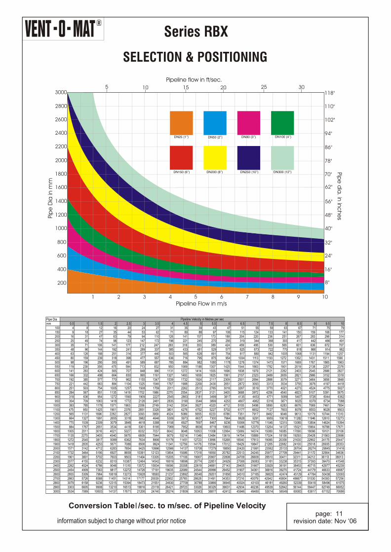
Sizing for VacuumCalculate necessary valve orifice sizes independently for each apex point.
Determine the smallest air release and vacuum break valve capable of admitting air into the pipeline equal to the potential water flow out of the pipeline whilst not exceeding a differential pressure that would put the pipeline and gasket joints at risk due to negative internal pressure. We recommend 0.35 bar (5 psi) Dp or lower. This exercise is simplified on pages 11 and 12 of this catalogue. Be cautious of air valve designs with spherical floats as a low pressure zone is created above the float which causes it to partially close off the large orifice during air intake.
Note that vacuum protection is dependent on valve size selection and orifice size relative to the nominal size of the valve. In sizing air valves be cautious of designs with restricted orifice diameters, i.e., orifice diameters that are smaller than the nominal size of the valve, as this could lead to insufficient vacuum protection and pipe collapse if not accommodated for. Vent-O-Mat large orifice diameters and flow path through the valve is equal to the nominal size of the valve e.g. a DN100 (4") valve has a 100mm (4") orifice. This ensures the least possible resistance to the intake of air and consequently the least possible negative pressure within a draining pipeline.
Sizing for DischargeIf a Vent-O-Mat air valve is sized correctly for air intake, discharge should not be a factor in sizing as all air will be discharged through the large orifice or "Anti-Shock" orifice (refer to RBX operation on pages 1 and 2 of this catalogue). If this information is used for the sizing of air valves other than Vent-O-Mat, we recommend that a valve be selected that is capable of discharging air equal to the filling rate, whilst not exceeding a differential of 0.05 bar (0.725 psi) across the large orifice in order to prevent pressure surge and water hammer.
Pressurized Air DischargeEffective discharge by an air release and vacuum break valve of pressurised air depends on the existence of a "Critical Relationship" between the area of the small orifice and the mass of the control float, i.e., the mass of the float must be greater than the force created by the working pressure acting on the orifice area. If the float is relatively too light or the orifice area relatively too great, the float will be held against the orifice even when not buoyed, and air discharge will not take place.
Surge Alleviation
It is imperative, due to the unpredictable nature of pipeline operation, that every air release and vacuum break valve should as standard, incorporate a surge and water hammer alleviation mechanism. This mechanism should only be activated in the instance of high velocity air discharge or pump trip (where the separated liquid columns rejoin at excessive velocities). The alleviation of surge and/or water hammer must be achieved by deceleration of the approaching liquid prior to valve closure (see operation of RBX on pages 1 and 2 of this catalogue). Relief mechanisms that act subsequent to valve closure cannot react in the low millisecond time span required and are therefore unacceptable.
Kindly contact the manufacturer for free copies of the Vent-O-Mat publications; "Points to Consider when Sizing and Position Air Release and Vacuum Break Valves" and "Air Valve Technology Reviewed", should you require more information on the phenomena of surge and water hammer as a result of air release, as well as the functional limits of all available air valve designs and configurations.
Vent-O-Mat has an interactive sizing programme available on the Internet. The website address is: http://www.ventomat.com. You can, should you experience any problems, or need additional assistance, contact us at our E Mail address: [email protected]
R
Series RBX
information subject to change without prior notice page: 10revision date: Nov ‘06
R
Series RBX
SELECTION & POSITIONING
5 10 15 20 25 30118"
110"
102"
94"
86"
78"
70"
62"
56"
48"
40"
32"
24"
16"
8"
Pipeline flow in ft/sec.
Pipe
dia
. in in
che
s
Conversion Table l /sec. to m/sec. of Pipeline Velocity
information subject to change without prior notice page: 11revision date: Nov ‘06
information subject to change without prior notice
page: 12revision date: Nov ‘06
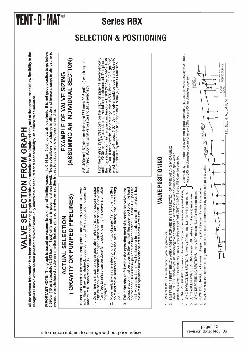
A Ø
40
0m
m (1
6")
pip
elin
e d
rain
ing
at 3
77
l/se
c (9
9.6
ga
l/se
c) w
hic
h e
qu
ate
s to
3m
/se
c. (9
.85
ft/s
), w
ha
t va
lve
siz
e s
ho
uld
be
se
lect
ed
?
Fro
m th
e 3
m/s
ec.
(9
.85
ft/s
) p
oin
t, o
n th
e g
rap
h o
n p
ag
e 1
1, m
ove
ve
rtic
ally
u
ntil
th
e Ø
40
0 m
m (
16
") p
ipe
siz
e h
orizo
nta
l lin
e is
inte
rse
cte
d. T
his
pla
ces
the
inte
rse
ctio
n p
oin
t in
the
op
era
ting
ba
nd
of a
DN
80
(3
") V
en
t-O
-Ma
t RB
X
valv
e.
Bu
t, i
f fo
r e
xam
ple
, th
e d
rain
ag
e r
ate
is
50
3 l
/se
c. (
13
2.8
ga
l/se
c)
wh
ich
eq
ua
tes
to 4
m/s
ec.
(1
3.1
ft/s)
, th
e v
alv
e w
ou
ld b
e o
pe
ratin
g c
lose
to
it'
s lim
it a
nd
it m
ay
be
pru
de
nt t
o c
ha
ng
e to
a D
N1
00
(4")
Ve
nt-
O-M
at R
BX
.
R
Series RBX
SURGE & WATERHAMMER PROTECTIONIntroductionThe Vent-O-Mat Series RBX "Anti-Shock" air release and vacuum break valve, is the product of extensive research into the development of an efficient, but cost effective solution to surge problems (both mass liquid oscillation and elastic transient phenomena) associated with any operating pipeline. Automatic dampening, relevant to the pipeline's needs is provided by either one of three design features. These special features are unique in a pipeline component of such compact and economic design.
Surge Protection - Initial FillingThe RBX incorporates the additional floating "Anti-Shock" Orifice which is aerodynamically engineered to throttle air discharge when water approach velocity would otherwise become too great and induce an unacceptable pressure rise. The air throttling action increases resistance to the flow of the approaching water which consequently decelerates to a velocity which reduces the pressure rise when the valve closes (see operation of valve on pages 1 & 2). Vent-O-Mat series RBX is an essential precaution for pipeline priming.
Surge Protection - Pump Trip ConditionsIn instances where a pipeline experiences water column separation due to pump stoppage, high shock pressures can be generated when the separated water column rejoins. The Vent-O-Mat series RBX takes in air through the unobstructed large orifice when water column separation occurs, but controls the discharge of air through the "Anti-Shock" Orifice as the separated column commences to rejoin. The rejoining impact velocity is thereby considerably reduced to alleviate high surge pressures in the system (see operation of valve on pages 1 & 2). Other surge control measures may, dependant on pipeline profile, diameter and operating conditions, be needed to provide the primary surge alleviation function with the Vent-O-Mat air-valves forming an integral and valuable addition in a combined strategy for further reducing surge pressures. The benefit of the "Anti-Shock" Orifice can be readily demonstrated by suitable surge modelling software.
Surge Protection - Pipeline OperatingThe operation of valves and similar flow control devices can cause high-pressure transients in an operating pipeline. The unique, single chamber design of the Vent-O-Mat series RBX valve enables a pocket of air to be trapped in the valve chamber. Automatic operation of the small orifice control float regulates the volume of air entrapped.
The volume maintained in the valve will provide a cushioning benefit to the pipeline for short duration transient pressure "spikes". This effect can be modelled by the design engineer using suitable surge software.
Surge Protection - Primary Pipeline Surge Protection FailureIn instances where air vessels or other alleviation measures are utilised as primary surge protection and these devices fail, excessively high surge pressures will be generated. The same is true if pipeline demands are increased with time without the upgrading of initial surge protection equipment.
information subject to change without prior notice page: 13revision date: Nov ‘06
Protection by Vent-O-Mat Series RBX will provide the benefits already described. The valve in addition, has a pipeline over pressure safety feature which acts as a "rupture-disc". Operation of this feature will be without an explosive effect and without damage to valve. This feature consists of easily replaceable components such as gaskets and seals. This feature will thus provide surge alleviation in instances where surge pressures are abnormally high. The net alleviation effect can be taken into account by the design engineer using surge modelling software.
Computer ModellingThe effectiveness of Vent-O-Mat series RBX has been substantiated by independent third party testing and by thousands of applications globally. Effective computer modelling, based on practical tests, has been ensured in the well-known and respected commercially available SURGE 2000 surge analysis software programme. Accurate results are also obtained by other commercially available surge analysis software programmes such as FLOWMASTER and TRANSAM.
Holistic Surge & Water Hammer ProtectionVent-O-Mat forms an integral part of a well planned, holistic surge protection strategy that should, according to application needs and financial constraints, include surge vessels, check valves, control valves and/or any other equipment needed to alleviate unacceptable surge behaviour.
Technical and Financial BenefitsThe Vent-O-Mat series RBX valve offers definite financial and technical advantages when incorporated as part of a holistic surge protection strategy. This includes: 1. Improved alleviation of surge behaviour including reduction of:
- Surge pressure magnitudes by slowing surge velocities- Duration of oscillation following a pump trip, as the air-valve continuously absorbs and
dissipates the energies of the surge.
2. Potential for reduction in size and/or quantity of conventional surge protection devices such as surge vessels etc.
3. Automatic protection during initial filling when most surge protection devices are not operational.
4. Holistic protection as each air valve installed has design features to automatically damp surges.
5. The valve is virtually maintenance free.
ServiceVent-O-Mat is committed to finding the most cost effective and efficient solution to pipeline complexities. Services include air valve sizing and positioning and assistance to consulting engineers on defining appropriate surge and water hammer protection strategies. Vent-O-Mat has built a sound relationship with many international consulting firms and has gained global recognition for selling solutions!
R
Series RBX
SURGE & WATERHAMMER PROTECTION
information subject to change without prior notice page: 14revision date: Nov ‘06
R
Series RBX
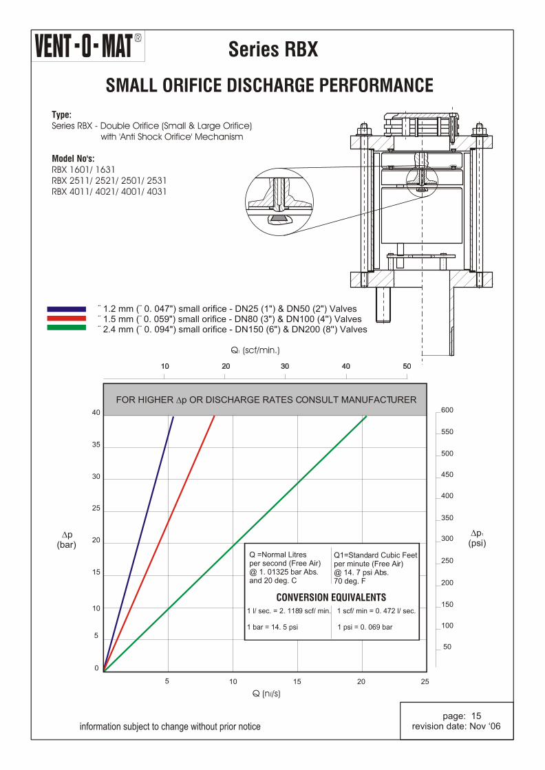
SMALL ORIFICE DISCHARGE PERFORMANCE
Type:Series RBX - Double Orifice (Small & Large Orifice) with 'Anti Shock Orifice' Mechanism
CONVERSION EQUIVALENTS1 l/ sec. = 2. 1189 scf/ min. 1 scf/ min = 0. 472 l/ sec. 1 bar = 14. 5 psi 1 psi = 0. 069 bar
information subject to change without prior notice page: 15revision date: Nov ‘06
R
Series RBX
Why?
information subject to change without prior notice
"ANTI-SHOCK" - "ANTI-SURGE" - The RBX is the only air release valve available that is supplied as standard with a mechanism which operates automatically to prevent pipeline damage from the high induced pressure transients associated with high velocity air discharge. Surge resulting from liquid column separation and liquid oscillation is dramatically reduced as an automatic function of this mechanism. PERFORMANCE - The RBX has been designed and developed to provide the optimum usable and safe performance relative to all functions. Selection data has been substantiated through CSIR and other testing and can therefore, be confidently referenced. QUALITY - The RBX economically offers the highest quality construction and materials available in an air release and vacuum break valve. Stringent manufacturing and test procedures are maintained to ensure the best possible service and reliability is given by every valve produced. SERVICEABILITY - The RBX design facilitates extreme ease of service and maintenance. Components are in corrosion free materials to allow problem free disassembly and reassembly even after many years of operation. All maintenance spares are replaceable without special tools or skills. VACUUM BREAK - The RBX series large orifice diameters equal the nominal size of the valve, i.e., a DN200 (8") valve has a DN200 (8") orifice. This ensures the least possible resistance to the intake of air and consequently the least possible negative pressure within a draining pipeline. COMPACTNESS - Although extremely robust the RBX valve's lightweight and compact construction offers handling transport and installation advantages. BACK UP - Vent-O-Mat provides highly committed customer orientated sales, service, spares and technical back up - TRY US!!!
page: 16revision date: Nov ‘06
R
Series RBX
PURCHASE SPECIFICATIONVENT -O- MAT MODEL NO.
Page 7 - Series RBX - DN25 (1") or DN50 (2") with BSP (ISO R7) or NPT, Screwed Male Connection.
Page 8 - Series RBX - DN80 (3") or DN100 (4") Flanged Connection.
Page 9 - Series RBX - DN150 (6") or DN200 (8") Flanged Connection.
CONSTRUCTION & DESIGN
The air release & vacuum break valve shall be of the compact single chamber design with solid cylindrical
H.D.P.E. control Floats housed in a tubular Stainless Steel Body with epoxy powder coated Mild Steel or
Stainless Steel ends secured by means of Stainless Steel Tie Rods.
The valve shall have an integral 'Anti-Shock' Orifice mechanism which shall operate automatically to limit
transient pressure rise or shock induced by closure to 1.5 x valve rated working pressure.
The intake orifice area shall be equal to the nominal size of the valve i.e., a 150mm (6") valve shall have a
150mm (6") intake orifice.
Large orifice sealing shall be effected by the flat face of the control float seating against a EPDM rubber 'O' ring
housed in a dovetail groove circumferentially surrounding the orifice.
Discharge of pressurized air shall be controlled by the seating & unseating of a Small Orifice Nozzle on a EPDM
rubber seal affixed into the control float. The Nozzle shall have a flat seating land surrounding the orifice so that
the damage to the rubber seal is prevented.
The valve construction shall be proportioned with regard to material strength characteristics, so that
deformation, leaking or damage of any kind does not occur by submission to one and half times the designed
working pressure.
The valve design shall incorporate an over pressure safety feature that will fail without an explosive effect, such
as is normally the case when highly compressed air is released suddenly. The feature shall consist of easily
replaceable components such as Gaskets, Seals or the like.
Connection to the valve inlet shall be facilitated by a screwed BSP (ISO R7) or NPT male end (DN25 (1") &
DN50 (2") only) or a flanged end conforming to PN10, 16, 25 or 40 ratings of BS4504 or SABS 1123 Standards
and ANSI B16.5 Class 150 or Class 300 Standards.
Nuts, washers, or jointing gaskets shall be excluded.
Optional: Provision of a ¼" BSP/ NPT Test/ Bleed Cock.
OPERATION
1. Prior to the ingress of liquid into the valve chamber, as when the pipeline is being filled, valves shall vent
through the large orifice when water approach velocities are relative to a transient pressure rise, on valve
closure, of < 1.5 x valve rated pressure.
At higher water approach velocities, which have a potential to induce transient pressure rises > 1.5 x
valve rated pressure on valve closure, the valve shall automatically discharge air through the Anti Shock
Orifice and reduce water approach velocity, so that on closure a maximum transient pressure rise of < 1.5 x
valve rated pressure is realised.
2. Valves shall not exhibit leaks or weeping of liquid past the large orifice seal at operating pressures of 0.5 bar
(7.25 psi) to one and a half times the rated working pressure.
3. Valves shall respond to the presence of air by discharging it through the small orifice at pressures within a
specified design range, i.e. 0.5 bar (7.25 psi) to 16 bar (232 psi), 25 bar (363 psi) or 40 bar (580 psi), and shall
Remain leak tight in the absence of air.
4. Valves shall react immediately to pipeline drainage or water column separation by the full opening of the
large orifice so as to allow unobstructed air intake at the lowest possible negative internal pipeline pressure.
Flanged ends for DN80 and DN100 shall be supplied with the requisite number of Stainless Steel screwed studs
inserted for alignment to the specified standard.
information subject to change without prior notice page: 17revision date: Nov ‘06
information subject to change without prior notice page: 18revision date: Nov ‘06
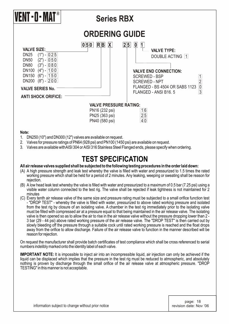
Note:1. DN250 (10") and DN300 (12") valves are available on request.2. Valves for pressure ratings of PN64 (928 psi) and PN100 (1450 psi) are available on request.3. Valves are available with AISI 304 or AISI 316 Stainless Steel Flanged ends, please specify when ordering.
TEST SPECIFICATION
All air release valves supplied shall be subjected to the following testing procedures in the order laid down:(A) A high pressure strength and leak test whereby the valve is filled with water and pressurized to 1.5 times the rated
working pressure which shall be held for a period of 2 minutes. Any leaking, weeping or sweating shall be reason for rejection.
(B) A low head leak test whereby the valve is filled with water and pressurized to a maximum of 0.5 bar (7.25 psi) using a visible water column connected to the test rig. The valve shall be rejected if leak tightness is not maintained for 2 minutes
(C) Every tenth air release valve of the same size and pressure rating must be subjected to a small orifice function test - "DROP TEST" - whereby the valve is filled with water, pressurized to above rated working pressure and isolated from the test rig by closure of an isolating valve. A chamber in the test rig immediately prior to the isolating valve must be filled with compressed air at a pressure equal to that being maintained in the air release valve. The isolating valve is then opened so as to allow the air to rise in the air release valve without the pressure dropping lower than 2 - 3 bar (29 - 44 psi) above rated working pressure of the air release valve. The "DROP TEST" is then carried out by slowly bleeding off the pressure through a suitable cock until rated working pressure is reached and the float drops away from the orifice to allow discharge. Failure of the air release valve to function in the manner described will be reason for rejection.
On request the manufacturer shall provide batch certificates of test compliance which shall be cross referenced to serial numbers indelibly marked onto the identity label of each valve. IMPORTANT NOTE: It is impossible to inject air into an incompressible liquid, air injection can only be achieved if the liquid can be displaced which implies that the pressure in the test rig must be reduced to atmospheric, and absolutely nothing is proven by discharge through the small orifice of the air release valve at atmospheric pressure. "DROP TESTING" in this manner is not acceptable.
R
page: 19revision date: Nov ‘06
Series RBXb
OPERATION
information subject to change without prior notice
PRE NOTES:
It is good engineering practice, for vertical turbine pumps and deepwell, submersible pump applications, to install air valves prior to the pump discharge check valve. The purpose of these valves is to prevent air entry into the pipeline and to break vacuum in the vertical riser upon pump shutoff. Operation of conventional air valves in this application is such that the air in the vertical riser is released very rapidly upon pump startup, resulting in very high pressure transients when the water column slams the air valve shut and/or slams into the closed discharge check valve.
The Vent-O-Mat Series RBXb valve has specifically been developed for use on deep well submersible pump and vertical turbine pump applications where they are installed prior to the pump discharge check valve to fulfill the following functions:
Provide effective and controlled release of air in the vertical riser upon pump startup.Dampen surge pressures upon pump startup. Provide vacuum protection when the pump stops and the vertical column drains.
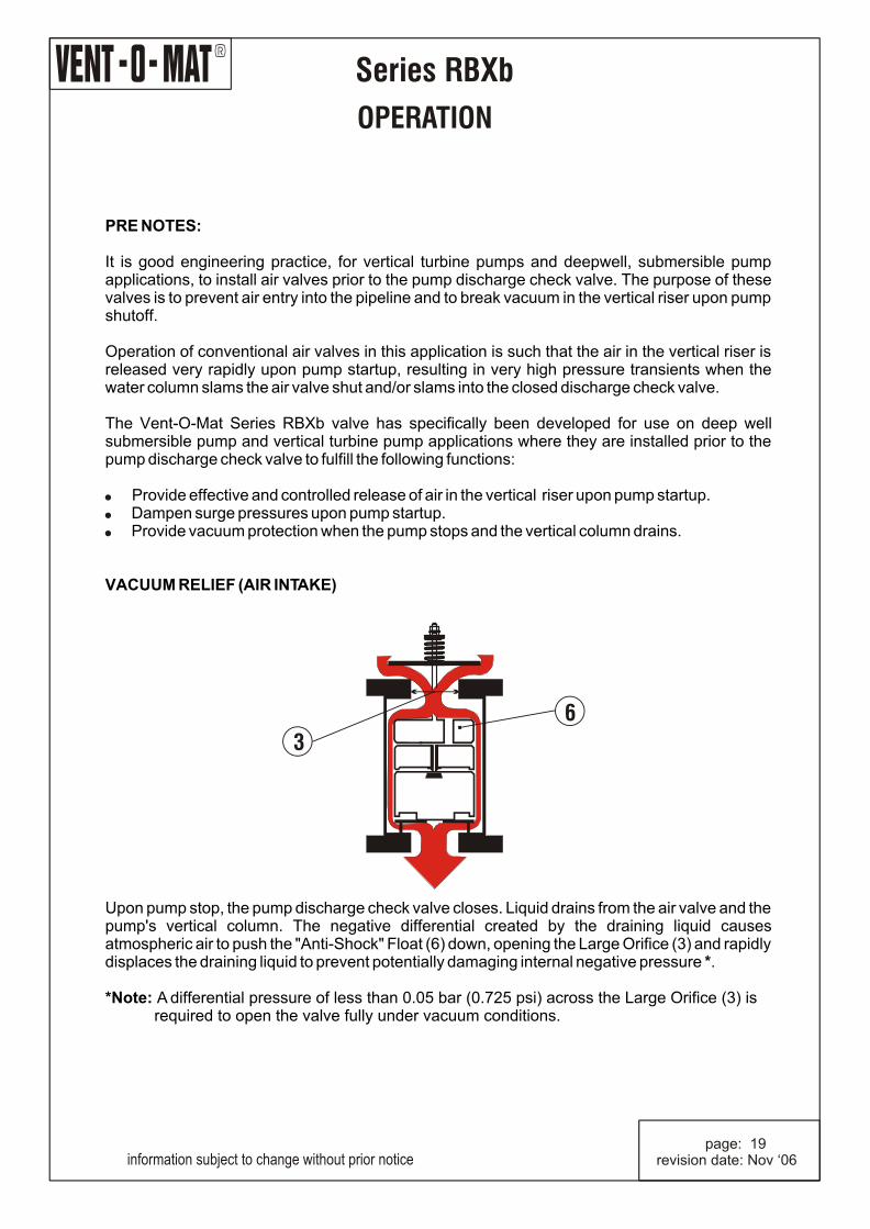
VACUUM RELIEF (AIR INTAKE)
Upon pump stop, the pump discharge check valve closes. Liquid drains from the air valve and the pump's vertical column. The negative differential created by the draining liquid causes atmospheric air to push the "Anti-Shock" Float (6) down, opening the Large Orifice (3) and rapidly displaces the draining liquid to prevent potentially damaging internal negative pressure *.
*Note: A differential pressure of less than 0.05 bar (0.725 psi) across the Large Orifice (3) is required to open the valve fully under vacuum conditions.
!
!
!
3
6
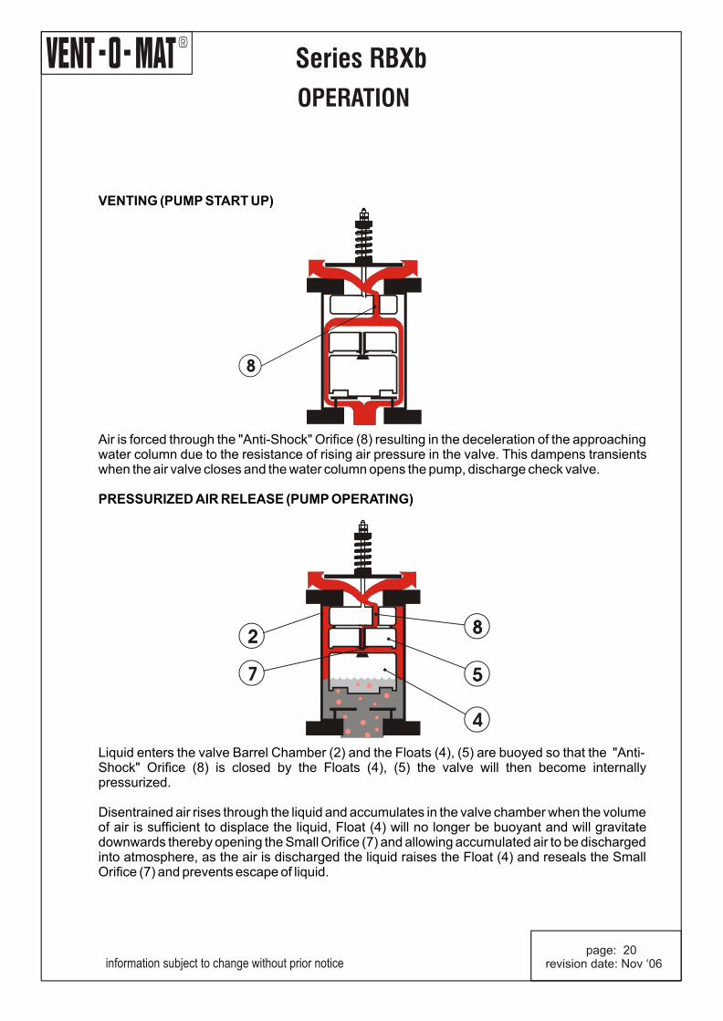
VENTING (PUMP START UP)
Air is forced through the "Anti-Shock" Orifice (8) resulting in the deceleration of the approaching water column due to the resistance of rising air pressure in the valve. This dampens transients when the air valve closes and the water column opens the pump, discharge check valve. PRESSURIZED AIR RELEASE (PUMP OPERATING)
Liquid enters the valve Barrel Chamber (2) and the Floats (4), (5) are buoyed so that the "Anti-Shock" Orifice (8) is closed by the Floats (4), (5) the valve will then become internally pressurized. Disentrained air rises through the liquid and accumulates in the valve chamber when the volume of air is sufficient to displace the liquid, Float (4) will no longer be buoyant and will gravitate downwards thereby opening the Small Orifice (7) and allowing accumulated air to be discharged into atmosphere, as the air is discharged the liquid raises the Float (4) and reseals the Small Orifice (7) and prevents escape of liquid.
R
Series RBXb
OPERATION
information subject to change without prior notice page: 20revision date: Nov ‘06
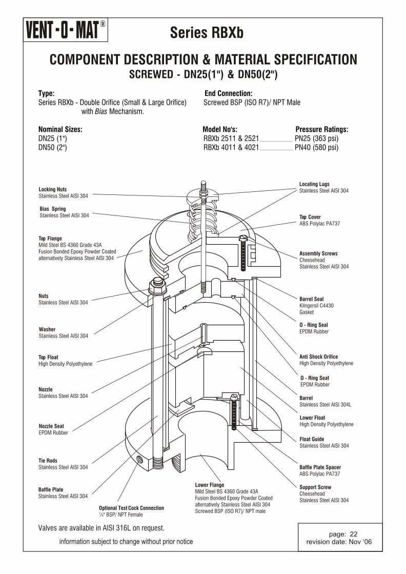
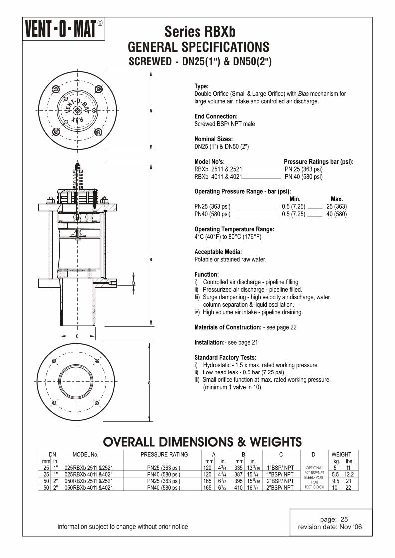
GENERAL SPECIFICATIONS SCREWED - DN25(1") & DN50(2")
Series RBXb
information subject to change without prior notice page: 25revision date: Nov ‘06
Type:Double Orifice (Small & Large Orifice) with Bias mechanism for large volume air intake and controlled air discharge. End Connection:Screwed BSP/ NPT male Nominal Sizes:DN25 (1") & DN50 (2") Model No's: Pressure Ratings bar (psi):RBXb 2511 & 2521 PN 25 (363 psi)RBXb 4011 & 4021 PN 40 (580 psi) Operating Pressure Range - bar (psi): Min. Max.PN25 (363 psi) 0.5 (7.25) 25 (363)PN40 (580 psi) 0.5 (7.25) 40 (580) Operating Temperature Range:4°C (40°F) to 80°C (176°F) Acceptable Media:Potable or strained raw water. Function:i) Controlled air discharge - pipeline fillingii) Pressurized air discharge - pipeline filled.Iii) Surge dampening - high velocity air discharge, water column separation & liquid oscillation.iv) High volume air intake - pipeline draining.
Materials of Construction: - see page 22
Installation:- see page 21 Standard Factory Tests:i) Hydrostatic - 1.5 x max. rated working pressureii) Low head leak - 0.5 bar (7.25 psi)iii) Small orifice function at max. rated working pressure (minimum 1 valve in 10).
OVERALL DIMENSIONS & WEIGHTS
A
O- -MTN AE T
V
RXB
A
D
B
C
DN MODEL No. PRESSURE RATING A B C D WEIGHT mm in. mm in. mm in. kg. lbs
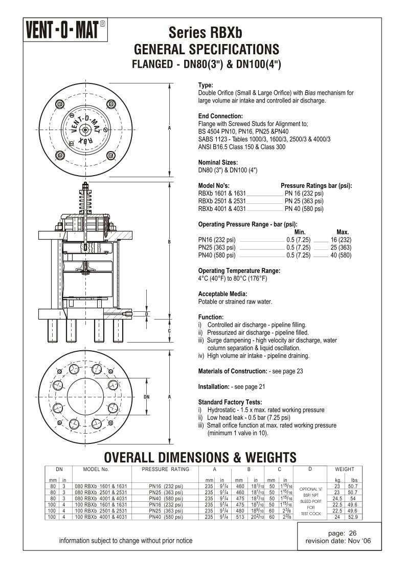
Type:Double Orifice (Small & Large Orifice) with Bias mechanism for large volume air intake and controlled air discharge.
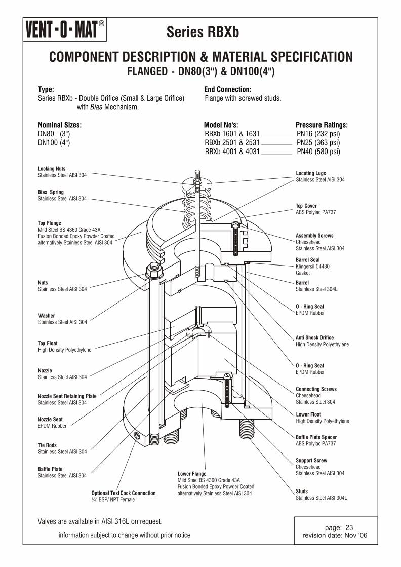
End Connection:Flange with Screwed Studs for Alignment to;BS 4504 PN10, PN16, PN25 &PN40SABS 1123 - Tables 1000/3, 1600/3, 2500/3 & 4000/3ANSI B16.5 Class 150 & Class 300 Nominal Sizes:DN80 (3") & DN100 (4") Model No's: Pressure Ratings bar (psi):RBXb 1601 & 1631 PN 16 (232 psi)RBXb 2501 & 2531 PN 25 (363 psi)RBXb 4001 & 4031 PN 40 (580 psi) Operating Pressure Range - bar (psi): Min. Max.PN16 (232 psi) 0.5 (7.25) 16 (232)PN25 (363 psi) 0.5 (7.25) 25 (363)PN40 (580 psi) 0.5 (7.25) 40 (580) Operating Temperature Range:4°C (40°F) to 80°C (176°F) Acceptable Media:Potable or strained raw water. Function:i) Controlled air discharge - pipeline filling.ii) Pressurized air discharge - pipeline filled.iii) Surge dampening - high velocity air discharge, water column separation & liquid oscillation.iv) High volume air intake - pipeline draining.
Materials of Construction: - see page 23
Installation: - see page 21
Standard Factory Tests:i) Hydrostatic - 1.5 x max. rated working pressureii) Low head leak - 0.5 bar (7.25 psi)iii) Small orifice function at max. rated working pressure (minimum 1 valve in 10).
OVERALL DIMENSIONS & WEIGHTS
information subject to change without prior notice
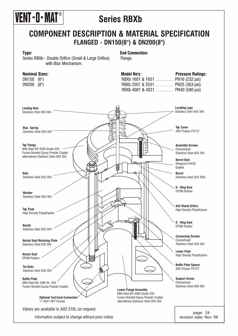
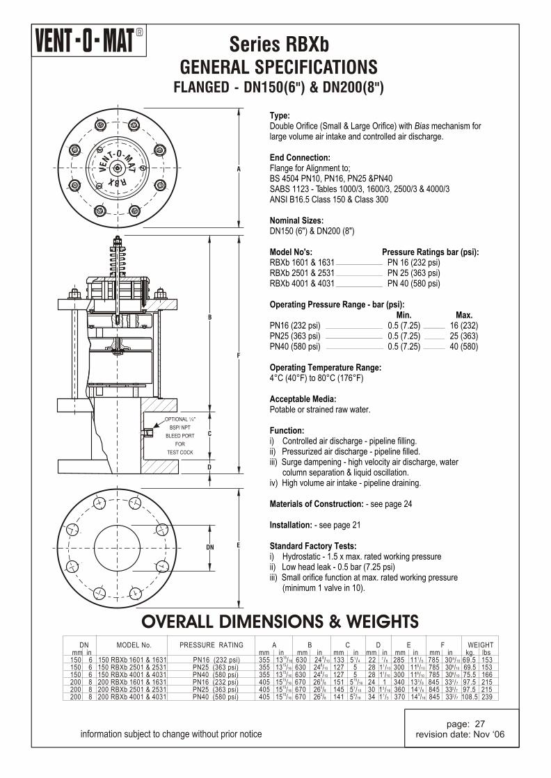
Type:Double Orifice (Small & Large Orifice) with Bias mechanism for large volume air intake and controlled air discharge.
End Connection:Flange for Alignment to;BS 4504 PN10, PN16, PN25 &PN40SABS 1123 - Tables 1000/3, 1600/3, 2500/3 & 4000/3ANSI B16.5 Class 150 & Class 300 Nominal Sizes:DN150 (6") & DN200 (8") Model No's: Pressure Ratings bar (psi):RBXb 1601 & 1631 PN 16 (232 psi)RBXb 2501 & 2531 PN 25 (363 psi)RBXb 4001 & 4031 PN 40 (580 psi) Operating Pressure Range - bar (psi): Min. Max.
PN25 (363 psi) 0.5 (7.25) 25 (363)PN40 (580 psi) 0.5 (7.25) 40 (580) Operating Temperature Range:4°C (40°F) to 80°C (176°F) Acceptable Media:Potable or strained raw water. Function:i) Controlled air discharge - pipeline filling.ii) Pressurized air discharge - pipeline filled.iii) Surge dampening - high velocity air discharge, water column separation & liquid oscillation.iv) High volume air intake - pipeline draining.
Materials of Construction: - see page 24
Installation: - see page 21
Standard Factory Tests:i) Hydrostatic - 1.5 x max. rated working pressureii) Low head leak - 0.5 bar (7.25 psi)iii) Small orifice function at max. rated working pressure (minimum 1 valve in 10).
PN16 (232 psi) 0.5 (7.25) 16 (232)
OVERALL DIMENSIONS & WEIGHTS
information subject to change without prior notice page: 27revision date: Nov ‘06
A
EDN
OPTIONAL ¼"
BSP/ NPT
BLEED PORT
FOR
TEST COCK
D
C
B
F
O- -MTN AE T
V
RXB
DN MODEL No. PRESSURE RATING A B C D E F WEIGHT mm in mm in mm in mm in mm in mm in mm in kg. lbs
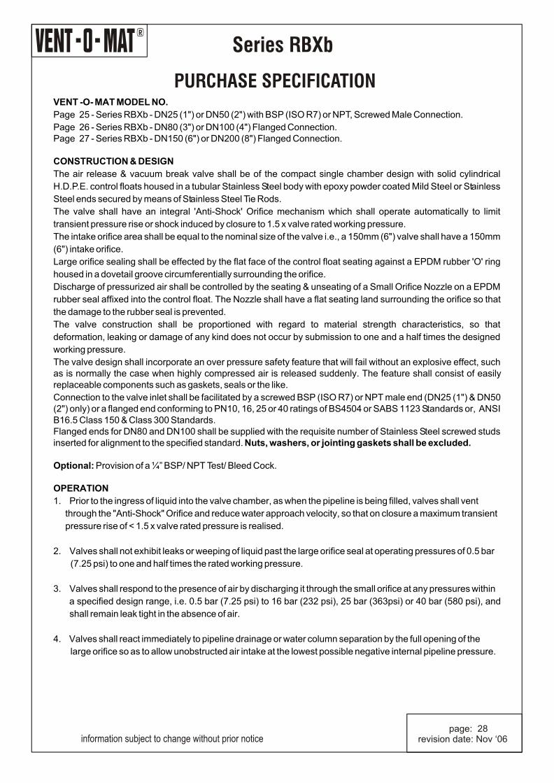
Page 25 - Series RBXb - DN25 (1") or DN50 (2") with BSP (ISO R7) or NPT, Screwed Male Connection.
Page 26 - Series RBXb - DN80 (3") or DN100 (4") Flanged Connection.Page 27 - Series RBXb - DN150 (6") or DN200 (8") Flanged Connection. CONSTRUCTION & DESIGN
The air release & vacuum break valve shall be of the compact single chamber design with solid cylindrical
H.D.P.E. control floats housed in a tubular Stainless Steel body with epoxy powder coated Mild Steel or Stainless
Steel ends secured by means of Stainless Steel Tie Rods.
The valve shall have an integral 'Anti-Shock' Orifice mechanism which shall operate automatically to limit
transient pressure rise or shock induced by closure to 1.5 x valve rated working pressure.
The intake orifice area shall be equal to the nominal size of the valve i.e., a 150mm (6") valve shall have a 150mm
(6") intake orifice.
Large orifice sealing shall be effected by the flat face of the control float seating against a EPDM rubber 'O' ring
housed in a dovetail groove circumferentially surrounding the orifice.
Discharge of pressurized air shall be controlled by the seating & unseating of a Small Orifice Nozzle on a EPDM
rubber seal affixed into the control float. The Nozzle shall have a flat seating land surrounding the orifice so that
the damage to the rubber seal is prevented.
The valve construction shall be proportioned with regard to material strength characteristics, so that
deformation, leaking or damage of any kind does not occur by submission to one and a half times the designed
working pressure.
The valve design shall incorporate an over pressure safety feature that will fail without an explosive effect, such as is normally the case when highly compressed air is released suddenly. The feature shall consist of easily replaceable components such as gaskets, seals or the like.
Connection to the valve inlet shall be facilitated by a screwed BSP (ISO R7) or NPT male end (DN25 (1") & DN50 (2") only) or a flanged end conforming to PN10, 16, 25 or 40 ratings of BS4504 or SABS 1123 Standards or, ANSI B16.5 Class 150 & Class 300 Standards.Flanged ends for DN80 and DN100 shall be supplied with the requisite number of Stainless Steel screwed studs inserted for alignment to the specified standard. Nuts, washers, or jointing gaskets shall be excluded. Optional: Provision of a ¼” BSP/ NPT Test/ Bleed Cock. OPERATION
1. Prior to the ingress of liquid into the valve chamber, as when the pipeline is being filled, valves shall vent
through the "Anti-Shock" Orifice and reduce water approach velocity, so that on closure a maximum transient
pressure rise of < 1.5 x valve rated pressure is realised.
2. Valves shall not exhibit leaks or weeping of liquid past the large orifice seal at operating pressures of 0.5 bar
(7.25 psi) to one and half times the rated working pressure.
3. Valves shall respond to the presence of air by discharging it through the small orifice at any pressures within
a specified design range, i.e. 0.5 bar (7.25 psi) to 16 bar (232 psi), 25 bar (363psi) or 40 bar (580 psi), and
shall remain leak tight in the absence of air.
4. Valves shall react immediately to pipeline drainage or water column separation by the full opening of the
large orifice so as to allow unobstructed air intake at the lowest possible negative internal pipeline pressure.
information subject to change without prior notice page: 28revision date: Nov ‘06
page: 29revision date: Nov ‘06
R
Series RBXv
OPERATION
information subject to change without prior notice
PRE NOTES:
There are instances where the hydraulic gradeline falls below a peak point during normal operation and where air inflow would adversely affect the normal operation and surge characteristic of the pipeline. Air intake may also be undesirable under pump trip conditions for pipelines running through a marsh (surge protection in these instances would be in the form of surge vessels and/or the pipeline will be designed for full vacuum). Vent-O-Mat offers the Series RBXv valve which has specifically been developed to ensure effective air release under all pipeline conditions but will not allow air entry under any operating condition.
VENTING OF A FILLING PIPELINE (SUB CRITICAL WATER APPROACH VELOCITY)
Air enters Orifice (1), travels through the annular space between the cylindrical floats (4) , (5), (6) and discharges through the Large Orifice (3) into atmosphere.*
*Note: A relatively low flow discharge rate is required to lift float and ensure air release.Float will seat on the Middle Flange (9) under vacuum conditions, effectively preventing air Entry.
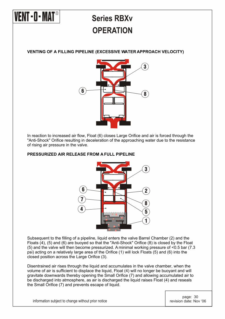
VENTING OF A FILLING PIPELINE (EXCESSIVE WATER APPROACH VELOCITY)
In reaction to increased air flow, Float (6) closes Large Orifice and air is forced through the "Anti-Shock" Orifice resulting in deceleration of the approaching water due to the resistance of rising air pressure in the valve.
PRESSURIZED AIR RELEASE FROM A FULL PIPELINE
Subsequent to the filling of a pipeline, liquid enters the valve Barrel Chamber (2) and the Floats (4), (5) and (6) are buoyed so that the "Anti-Shock" Orifice (8) is closed by the Float (5) and the valve will then become pressurized. A minimal working pressure of <0.5 bar (7.3 psi) acting on a relatively large area of the Orifice (1) will lock Floats (5) and (6) into the closed position across the Large Orifice (3). Disentrained air rises through the liquid and accumulates in the valve chamber, when the volume of air is sufficient to displace the liquid, Float (4) will no longer be buoyant and will gravitate downwards thereby opening the Small Orifice (7) and allowing accumulated air to be discharged into atmosphere, as air is discharged the liquid raises Float (4) and reseals the Small Orifice (7) and prevents escape of liquid.
page: 30revision date: Nov ‘06
R
Series RBXv
OPERATION
information subject to change without prior notice
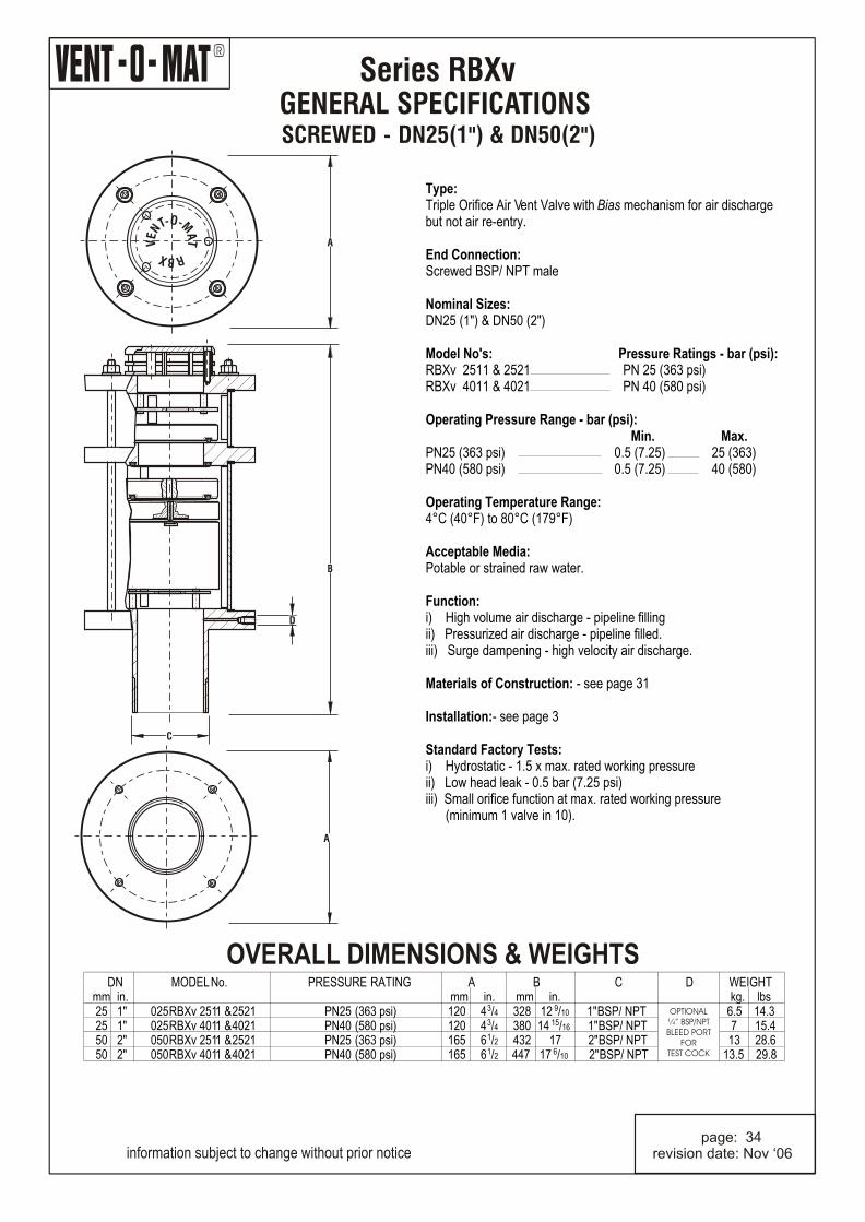
GENERAL SPECIFICATIONS SCREWED - DN25(1") & DN50(2")
Series RBXv
information subject to change without prior notice page: 34revision date: Nov ‘06
Type:Triple Orifice Air Vent Valve with Bias mechanism for air discharge but not air re-entry. End Connection:Screwed BSP/ NPT male Nominal Sizes:DN25 (1") & DN50 (2") Model No's: Pressure Ratings - bar (psi):RBXv 2511 & 2521 PN 25 (363 psi)RBXv 4011 & 4021 PN 40 (580 psi) Operating Pressure Range - bar (psi): Min. Max.PN25 (363 psi) 0.5 (7.25) 25 (363)PN40 (580 psi) 0.5 (7.25) 40 (580) Operating Temperature Range:4°C (40°F) to 80°C (179°F) Acceptable Media:Potable or strained raw water. Function:i) High volume air discharge - pipeline fillingii) Pressurized air discharge - pipeline filled.iii) Surge dampening - high velocity air discharge.
Materials of Construction: - see page 31
Installation:- see page 3
Standard Factory Tests:i) Hydrostatic - 1.5 x max. rated working pressureii) Low head leak - 0.5 bar (7.25 psi)iii) Small orifice function at max. rated working pressure (minimum 1 valve in 10).
OVERALL DIMENSIONS & WEIGHTS
A
A
D
B
C
O- -MTN AE T
V
RXB
DN MODEL No. PRESSURE RATING A B C D WEIGHT mm in. mm in. mm in. kg. lbs
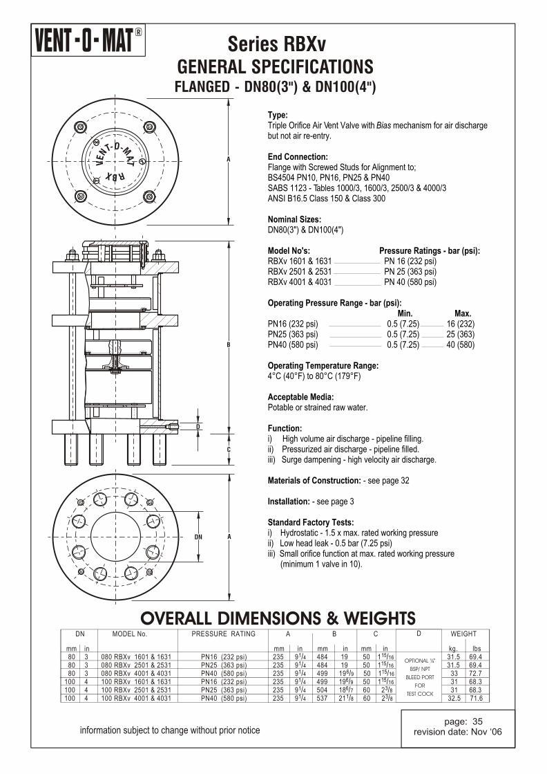
Type:Triple Orifice Air Vent Valve with Bias mechanism for air discharge but not air re-entry.
End Connection:Flange with Screwed Studs for Alignment to;BS4504 PN10, PN16, PN25 & PN40SABS 1123 - Tables 1000/3, 1600/3, 2500/3 & 4000/3ANSI B16.5 Class 150 & Class 300 Nominal Sizes:DN80(3") & DN100(4") Model No's: Pressure Ratings - bar (psi):RBXv 1601 & 1631 PN 16 (232 psi)RBXv 2501 & 2531 PN 25 (363 psi)RBXv 4001 & 4031 PN 40 (580 psi) Operating Pressure Range - bar (psi): Min. Max.PN16 (232 psi) 0.5 (7.25) 16 (232)PN25 (363 psi) 0.5 (7.25) 25 (363)PN40 (580 psi) 0.5 (7.25) 40 (580) Operating Temperature Range:4°C (40°F) to 80°C (179°F) Acceptable Media:Potable or strained raw water. Function:i) High volume air discharge - pipeline filling.ii) Pressurized air discharge - pipeline filled.iii) Surge dampening - high velocity air discharge.
Materials of Construction: - see page 32
Installation: - see page 3
Standard Factory Tests:i) Hydrostatic - 1.5 x max. rated working pressureii) Low head leak - 0.5 bar (7.25 psi)iii) Small orifice function at max. rated working pressure (minimum 1 valve in 10).
OVERALL DIMENSIONS & WEIGHTS
information subject to change without prior notice page: 35revision date: Nov ‘06
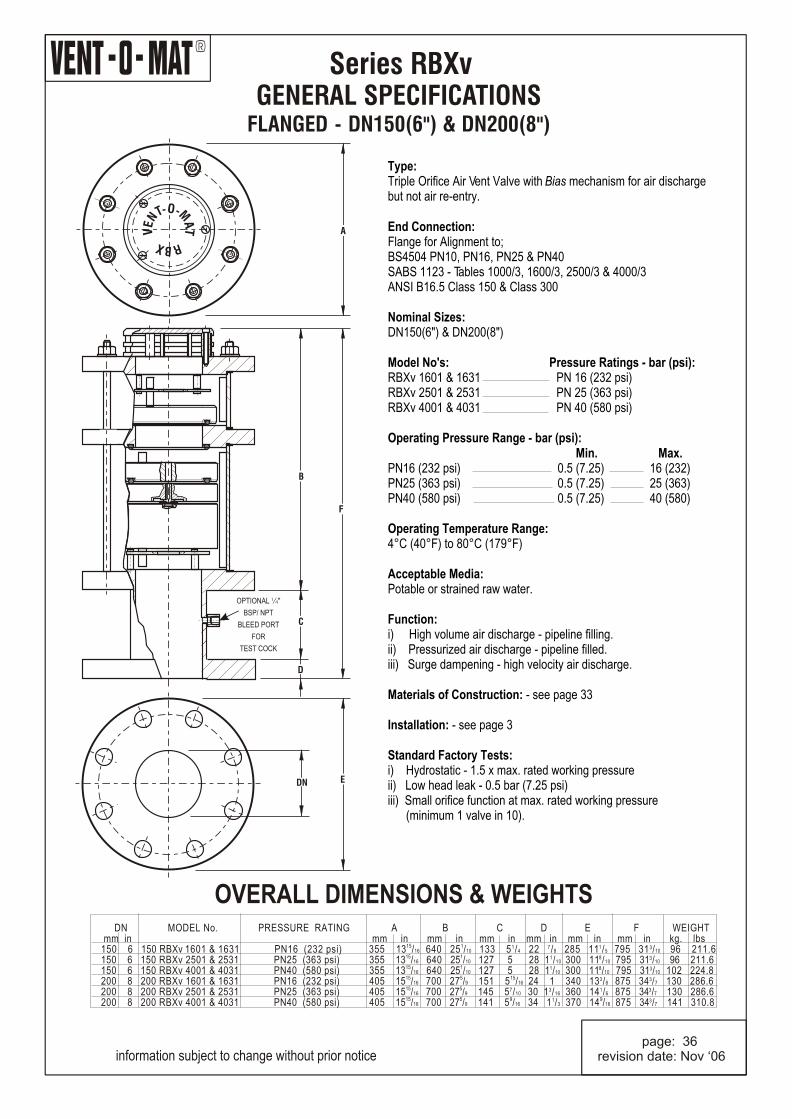
Type:Triple Orifice Air Vent Valve with Bias mechanism for air discharge but not air re-entry.
End Connection:Flange for Alignment to;BS4504 PN10, PN16, PN25 & PN40SABS 1123 - Tables 1000/3, 1600/3, 2500/3 & 4000/3ANSI B16.5 Class 150 & Class 300 Nominal Sizes:DN150(6") & DN200(8") Model No's: Pressure Ratings - bar (psi):RBXv 1601 & 1631 PN 16 (232 psi)RBXv 2501 & 2531 PN 25 (363 psi)RBXv 4001 & 4031 PN 40 (580 psi)
Operating Pressure Range - bar (psi): Min. Max.PN16 (232 psi) 0.5 (7.25) 16 (232)PN25 (363 psi) 0.5 (7.25) 25 (363)PN40 (580 psi) 0.5 (7.25) 40 (580) Operating Temperature Range:4°C (40°F) to 80°C (179°F) Acceptable Media:Potable or strained raw water. Function:i) High volume air discharge - pipeline filling.ii) Pressurized air discharge - pipeline filled.iii) Surge dampening - high velocity air discharge.
Materials of Construction: - see page 33
Installation: - see page 3
Standard Factory Tests:i) Hydrostatic - 1.5 x max. rated working pressureii) Low head leak - 0.5 bar (7.25 psi)iii) Small orifice function at max. rated working pressure (minimum 1 valve in 10).
OVERALL DIMENSIONS & WEIGHTS
information subject to change without prior notice page: 36revision date: Nov ‘06
O- -MTN AE T
V
RXB
A
EDN
OPTIONAL ¼"
BSP/ NPT
BLEED PORT
FOR
TEST COCK
D
C
B
F
DN MODEL No. PRESSURE RATING A B C D E F WEIGHT mm in mm in mm in mm in mm in mm in mm in kg. lbs
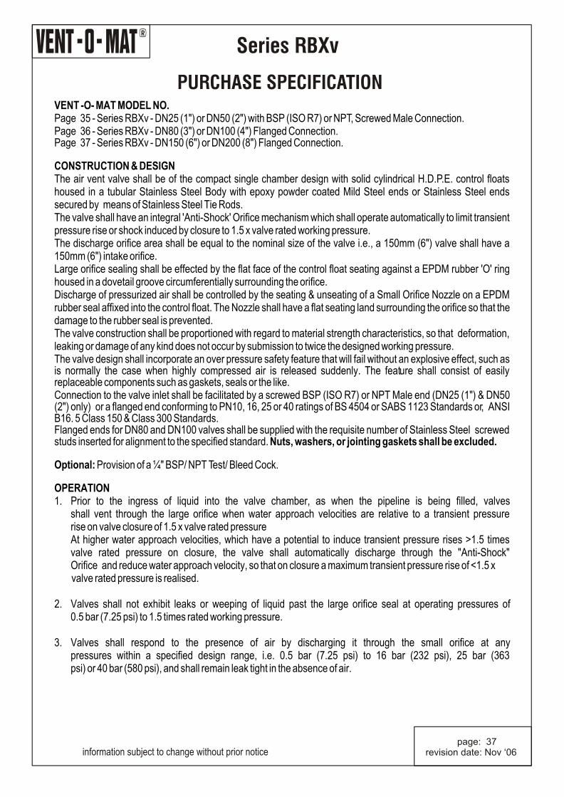
PURCHASE SPECIFICATIONVENT -O- MAT MODEL NO.Page 35 - Series RBXv - DN25 (1") or DN50 (2") with BSP (ISO R7) or NPT, Screwed Male Connection.Page 36 - Series RBXv - DN80 (3") or DN100 (4") Flanged Connection.Page 37 - Series RBXv - DN150 (6") or DN200 (8") Flanged Connection. CONSTRUCTION & DESIGNThe air vent valve shall be of the compact single chamber design with solid cylindrical H.D.P.E. control floats housed in a tubular Stainless Steel Body with epoxy powder coated Mild Steel ends or Stainless Steel ends secured by means of Stainless Steel Tie Rods.The valve shall have an integral 'Anti-Shock' Orifice mechanism which shall operate automatically to limit transient pressure rise or shock induced by closure to 1.5 x valve rated working pressure.The discharge orifice area shall be equal to the nominal size of the valve i.e., a 150mm (6") valve shall have a 150mm (6") intake orifice.Large orifice sealing shall be effected by the flat face of the control float seating against a EPDM rubber 'O' ring housed in a dovetail groove circumferentially surrounding the orifice.Discharge of pressurized air shall be controlled by the seating & unseating of a Small Orifice Nozzle on a EPDM rubber seal affixed into the control float. The Nozzle shall have a flat seating land surrounding the orifice so that the damage to the rubber seal is prevented.The valve construction shall be proportioned with regard to material strength characteristics, so that deformation, leaking or damage of any kind does not occur by submission to twice the designed working pressure.The valve design shall incorporate an over pressure safety feature that will fail without an explosive effect, such as is normally the case when highly compressed air is released suddenly. The feature shall consist of easily replaceable components such as gaskets, seals or the like.Connection to the valve inlet shall be facilitated by a screwed BSP (ISO R7) or NPT Male end (DN25 (1") & DN50 (2") only) or a flanged end conforming to PN10, 16, 25 or 40 ratings of BS 4504 or SABS 1123 Standards or, ANSI B16. 5 Class 150 & Class 300 Standards.Flanged ends for DN80 and DN100 valves shall be supplied with the requisite number of Stainless Steel screwed studs inserted for alignment to the specified standard. Nuts, washers, or jointing gaskets shall be excluded. Optional: Provision of a ¼" BSP/ NPT Test/ Bleed Cock. OPERATION1. Prior to the ingress of liquid into the valve chamber, as when the pipeline is being filled, valves
shall vent through the large orifice when water approach velocities are relative to a transient pressure rise on valve closure of 1.5 x valve rated pressureAt higher water approach velocities, which have a potential to induce transient pressure rises >1.5 times valve rated pressure on closure, the valve shall automatically discharge through the "Anti-Shock" Orifice and reduce water approach velocity, so that on closure a maximum transient pressure rise of <1.5 x
valve rated pressure is realised.
2. Valves shall not exhibit leaks or weeping of liquid past the large orifice seal at operating pressures of 0.5 bar (7.25 psi) to 1.5 times rated working pressure.
3. Valves shall respond to the presence of air by discharging it through the small orifice at any pressures within a specified design range, i.e. 0.5 bar (7.25 psi) to 16 bar (232 psi), 25 bar (363 psi) or 40 bar (580 psi), and shall remain leak tight in the absence of air.
information subject to change without prior notice page: 37revision date: Nov ‘06
information subject to change without prior notice page: 38revision date: Nov ‘06
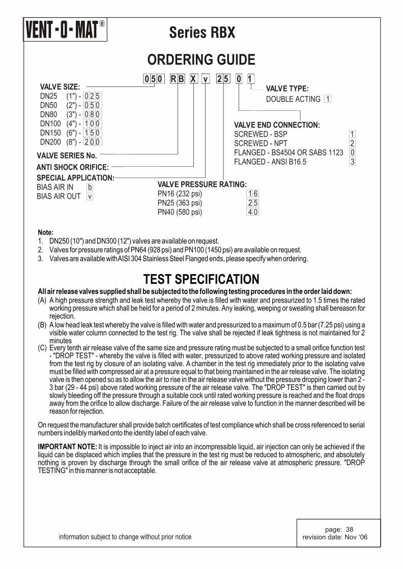
Note:1. DN250 (10") and DN300 (12") valves are available on request.2. Valves for pressure ratings of PN64 (928 psi) and PN100 (1450 psi) are available on request.3. Valves are available with AISI 304 Stainless Steel Flanged ends, please specify when ordering.
TEST SPECIFICATION
All air release valves supplied shall be subjected to the following testing procedures in the order laid down:(A) A high pressure strength and leak test whereby the valve is filled with water and pressurized to 1.5 times the rated
working pressure which shall be held for a period of 2 minutes. Any leaking, weeping or sweating shall bereason for rejection.
(B) A low head leak test whereby the valve is filled with water and pressurized to a maximum of 0.5 bar (7.25 psi) using a visible water column connected to the test rig. The valve shall be rejected if leak tightness is not maintained for 2 minutes
(C) Every tenth air release valve of the same size and pressure rating must be subjected to a small orifice function test - "DROP TEST" - whereby the valve is filled with water, pressurized to above rated working pressure and isolated from the test rig by closure of an isolating valve. A chamber in the test rig immediately prior to the isolating valve must be filled with compressed air at a pressure equal to that being maintained in the air release valve. The isolating valve is then opened so as to allow the air to rise in the air release valve without the pressure dropping lower than 2 - 3 bar (29 - 44 psi) above rated working pressure of the air release valve. The "DROP TEST" is then carried out by slowly bleeding off the pressure through a suitable cock until rated working pressure is reached and the float drops away from the orifice to allow discharge. Failure of the air release valve to function in the manner described will be reason for rejection.
On request the manufacturer shall provide batch certificates of test compliance which shall be cross referenced to serial numbers indelibly marked onto the identity label of each valve. IMPORTANT NOTE: It is impossible to inject air into an incompressible liquid, air injection can only be achieved if the liquid can be displaced which implies that the pressure in the test rig must be reduced to atmospheric, and absolutely nothing is proven by discharge through the small orifice of the air release valve at atmospheric pressure. "DROP TESTING" in this manner is not acceptable.
R
Series RBX
Complete the form below for any additional information and fax/post to:
VENT-O-MATP. O. Box 5064Benoni South1502South Africa
®VENT-O-MAT Series RGX Air Release & Vacuum Break Valvescompact Stainless Steel single chamber design with integral "Anti-Shock" surge dampening mechanism.
®VENT-O-MAT Series RC Air Release & Vacuum Break Valvescast air valve for irrigation and small reticulation systems.
glass reinforced polypropylene CATT air valve for industrial, irrigation and small reticulationsystems.
®LevelDex High Performance Endline Level Control Valvesend line valve with cushioned closing characteristics for level control in tanks and reservoirs.
®VENT-O-MAT Series RPS Air Release & Vacuum Break Valves
®VENT-O-MAT Series RBXc Air Release & Vacuum Break Valvescompact cast single chamber design with integral "Anti-Shock" surge dampening mechanism in an economical cast ductile iron construction.