Series TR Bearings Series TR Bearings Series TR Bearings Introduction Series TR designates a triple- row roller bearing configuration. Three independent rows of rollers transmit thrust, moment and radial loads simultaneously. Loads are applied to roller paths which are perpendicular to the load direction enabling each roller to be utilized in the most efficient manner possible. Construction These bearings are produced from special alloy steel through hardened to the appropriate level. The roller paths are induction hardened to 58-62 Rc. Rollers are made from A.I.S.I. 52100 steel. Advantages Series TR bearings, per unit size, offer more capacity than any other Avon design. The perpendicular orientation of the rollers minimizes the axial deflection under load, making the Series TR bearing the stiffest Avon design. Applications Ideal applications for Avon Series TR bearings include marine cranes, draglines, heavy-duty cranes, hydraulic shovels, stacker/reclaimers, tunnel borers, mooring buoys, machine tools and telescopes. Typical Cross Section 6-1
Transcript
Series TR BearingsSeries TR BearingsSeries TR Bearings
IntroductionSeries TR designates a triple-row roller bearing configuration. Three independent rows of rollers transmit thrust, moment and radial loads simultaneously. Loads are applied to roller paths which are perpendicular to the load direction enabling each roller to be utilized in the most efficient manner possible.
ConstructionThese bearings are produced from special alloy steel through hardened to the appropriate level. The roller paths are induction hardened to 58-62 Rc. Rollers are made from A.I.S.I. 52100 steel.
AdvantagesSeries TR bearings, per unit size, offer more capacity than any other Avon design. The perpendicular orientation of the rollers minimizes the axial deflection under load, making the Series TR bearing the stiffest Avon design.
ApplicationsIdeal applications for Avon Series TR bearings include marine cranes, draglines, heavy-duty cranes, hydraulic shovels, stacker/reclaimers, tunnel borers, mooring buoys, machine tools and telescopes.
Typical Cross Section
6-1
OBC # Holes Bolt IBC # Holes Bolt
Outer race Inner raceMOUNTING HOLES
5-3
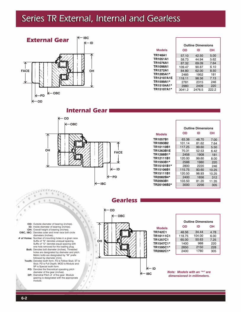
Series TR External, Internal and GearlessSeries TR External, Internal and GearlessSeries TR External, Internal and Gearless
Number of teeth in the gear.Face width of the gear (inches).Raceway capacity (Moment, Thrust and Radial) are based upon the Theoretical Stress Limit Static Load rating for a single axis. See page 2-6 for additional information. Contact Avon Bearings Engineering for analysis of combined loading applications. Note: Bolts may be the limiting factor from a capacity standpoint. Tooth capacity denotes the Tangential Tooth Capacity based upon the Lewis equation and including a 4:1 safety factor over the tensile strength of the steel.Denotes moment capacity of raceway, single-axis (ft.-lbs.).Denotes thrust or axial capacity of raceway, single-axis (lbs.).Denotes radial capacity of raceway, single-axis (lbs.).
Series TR External, Internal and GearlessSeries TR External, Internal and GearlessSeries TR External, Internal and Gearless
Outside diameter of bearing (inches).Inside diameter of bearing (inches).Overall height of bearing (inches).Denotes outer and inner race bolt circle diameters (inches).Number of mounting holes in a given race.Suffix of “N” denotes unequal spacing. Suffix of “O” denotes equal spacing with one hole removed for the loading plug.Denotes bolt diameter (inches). Threaded holes are designated by diameter and pitch. Metric bolts are designated by “M” prefix followed by diameter (mm).Denotes tooth form. FS is Fellow Stub; ST is Stub; FD is Full Depth; MOD is Module and SP is Special tooth form.Denotes the theoretical operating pitch diameter of the gear (inches).Diametral Pitch of of the gear. Module gearing is designated with the appropriate module.
OD:ID:
OH:OBC, IBC:
# of Holes:
Bolt:
Tooth:
PD:
DP:
PD
OHFACE
ID
OD
Note: Models with an “*” aredimensioned in millimeters.