Page 1
P R O D U C T & A P P L I C A T I O N H A N D B O O K V O L U M E V C108
C109 SERIES V
C113 CONSTRUCTION DETAILS
C115 CUSTOM FEATURES & OPTIONS
Series V Closed Circuit Cooling Towers
C125 ENGINEERING DATA
C134 STRUCTURAL SUPPORT
T A B L E O F C O N T E N T S
Page 2
C109 Q U E S T I O N S ? C A L L 4 1 0 . 7 9 9 . 6 2 0 0 O R V I S I T W W W . B A L T I M O R E A I R C O I L . C O M
The VF1 and VFL Closed Circuit Cooling Towers provide answers to some of the most challenging applications. These units are equipped to handle external static pressure, making them ideal for indoor installations and are available in a low profile version to accommodate limited ceiling or enclosure heights. Offering low installed costs, year-round operating reliability, and long service life, the VF1 and VFL Closed Circuit Cooling Towers provide an excellent solution for a large variety of fluids and processes.
Page 3
P R O D U C T & A P P L I C A T I O N H A N D B O O K V O L U M E V C110
BAC’s Series V Closed Circuit Cooling Towers: Solutions for Challenging Applications
Δ Δ Δ Δ Δ
Easy Maintenance
Ideal for External Static
Concerns
Low Environmental
Impact
Indoor/Outdoor Flexibility
Long Service
Life
Wide Range of CTI Certified Capacities 3.9 to 614 Nominal Tons in a Single Cell
Up to 4,470 USGPM for Process Applications
Page 4
C111 Q U E S T I O N S ? C A L L 4 1 0 . 7 9 9 . 6 2 0 0 O R V I S I T W W W . B A L T I M O R E A I R C O I L . C O M
Series V Benefits
› Low Environmental Impact ` ENERGY EFFICIENT
• CapacityiscertifiedbytheCoolingTechnologyInstituteusingwater,ethyleneglycol,andpropyleneglycol
• AllunitsmeetorexceedASHRAEStandard90.1energyefficiencyrequirements
• Closedloopcoolingfurtherminimizesprocessfouling,maintainingprocessefficiency
• Premiumefficient/inverterdutyfanmotors
• BALTIGUARD™FanSystemprovidesredundancyandenergysavingsbyprovidingaponymotor(optional)
` SOUND REDUCTION OPTIONS
• Centrifugalfanshaveinherentlylowsoundcharacteristics
• Factorydesignedsoundattenuationisavailableforboththeairintakeanddischarge(option)
• Soundsensitiveinstallationscanbeaccommodatedbyfacingthequietblankoffpaneltothesoundsensitivedirection
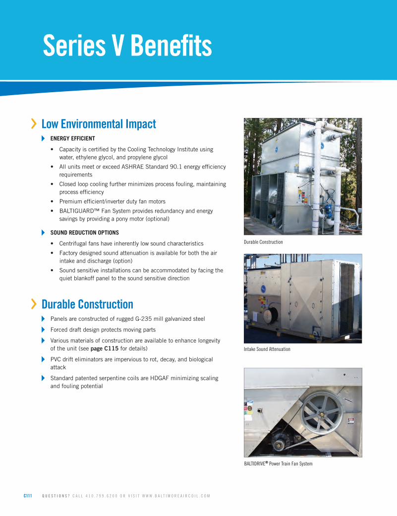
› Durable Construction ` PanelsareconstructedofruggedG-235millgalvanizedsteel
` Forceddraftdesignprotectsmovingparts
` Variousmaterialsofconstructionareavailabletoenhancelongevityoftheunit(seepage C115fordetails)
` PVCdrifteliminatorsareimpervioustorot,decay,andbiologicalattack
` StandardpatentedserpentinecoilsareHDGAFminimizingscalingandfoulingpotential
Durable Construction
Intake Sound Attenuation
BALTIDRIVE® Power Train Fan System
Page 5
P R O D U C T & A P P L I C A T I O N H A N D B O O K V O L U M E V C112
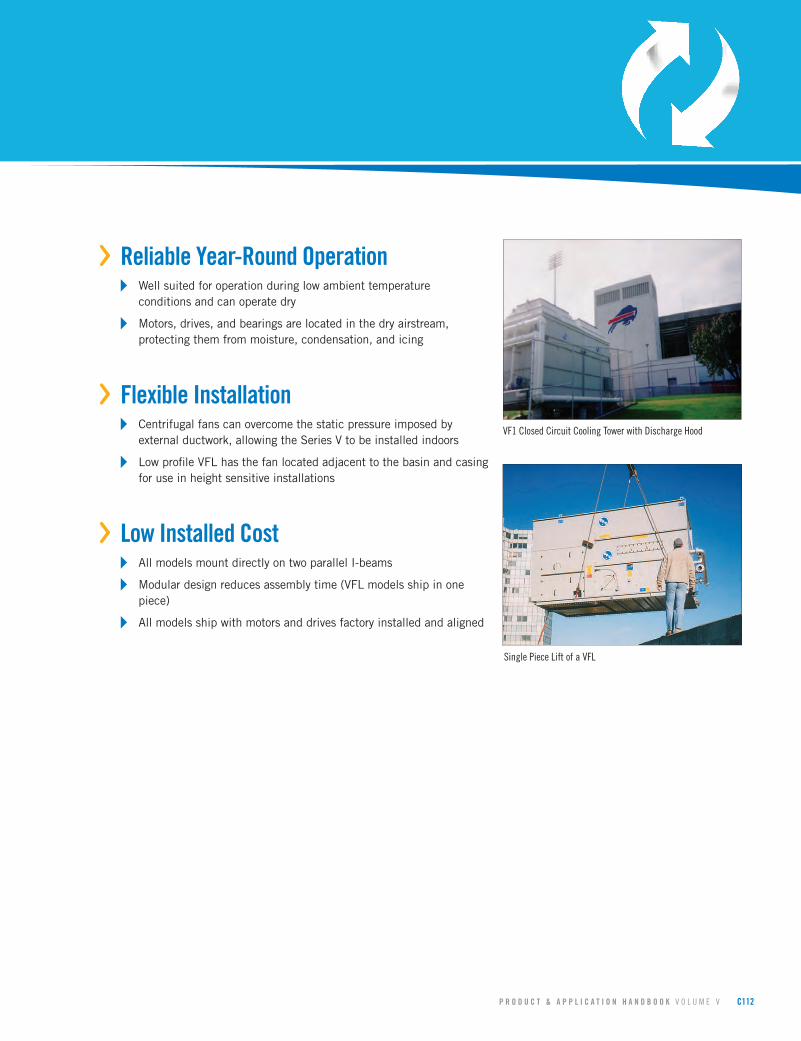
› Reliable Year-Round Operation ` Wellsuitedforoperationduringlowambienttemperature
conditionsandcanoperatedry
` Motors,drives,andbearingsarelocatedinthedryairstream,protectingthemfrommoisture,condensation,andicing
› Flexible Installation ` Centrifugalfanscanovercomethestaticpressureimposedby
externalductwork,allowingtheSeriesVtobeinstalledindoors
` LowprofileVFLhasthefanlocatedadjacenttothebasinandcasingforuseinheightsensitiveinstallations
› Low Installed Cost ` AllmodelsmountdirectlyontwoparallelI-beams
` Modulardesignreducesassemblytime(VFLmodelsshipinonepiece)
` Allmodelsshipwithmotorsanddrivesfactoryinstalledandaligned
VF1 Closed Circuit Cooling Tower with Discharge Hood
Single Piece Lift of a VFL
Page 6
C113 Q U E S T I O N S ? C A L L 4 1 0 . 7 9 9 . 6 2 0 0 O R V I S I T W W W . B A L T I M O R E A I R C O I L . C O M
Series V Construction Details
5YEAR
• WARRANTY •
BAC
MOTOR & DRIVE
V F 1 C O I L S E C T I O N
V F 1 C O L D W A T E R B A S I N
1
5
4
2
3
6
7
8
C113 Q U E S T I O N S ? C A L L 4 1 0 . 7 9 9 . 6 2 0 0 O R V I S I T W W W . B A L T I M O R E A I R C O I L . C O M
Page 7
P R O D U C T & A P P L I C A T I O N H A N D B O O K V O L U M E V C114
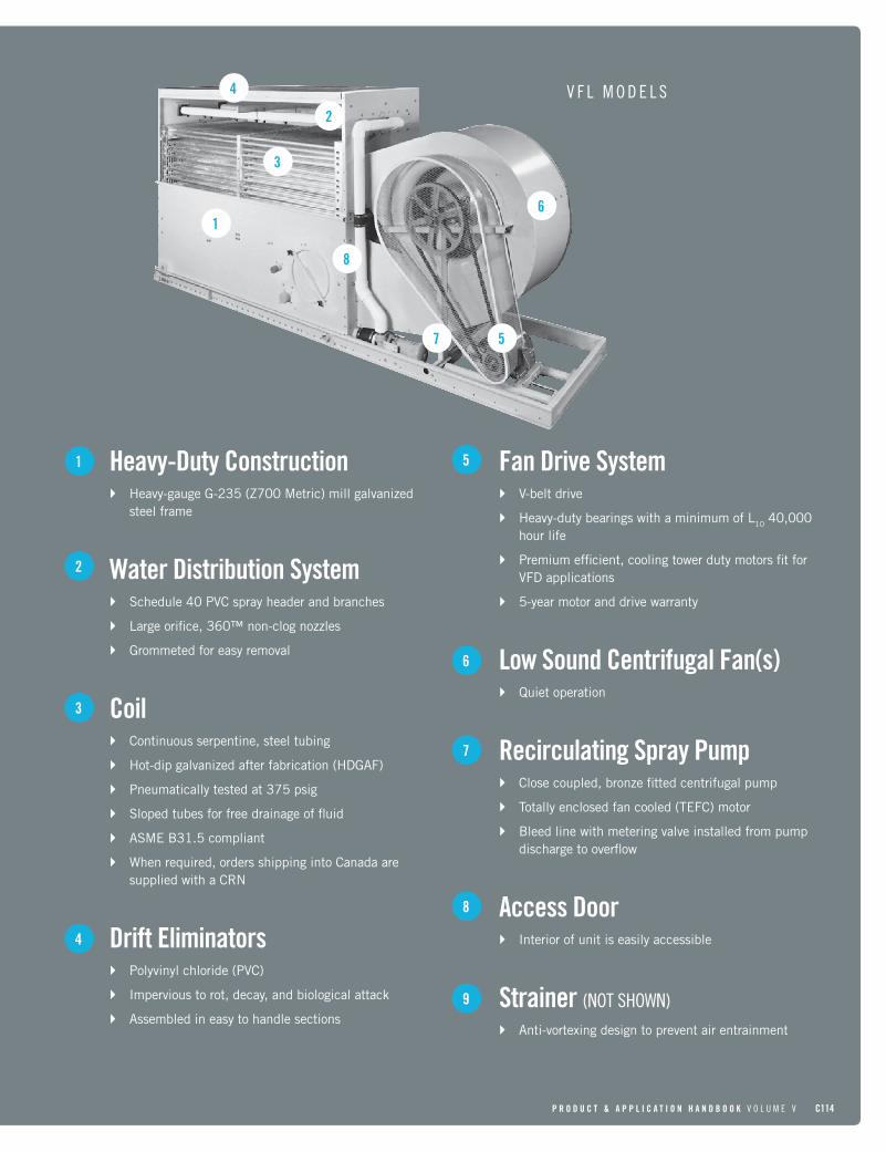
Fan Drive System` V-beltdrive
` Heavy-dutybearingswithaminimumofL1040,000hourlife
` Premiumefficient,coolingtowerdutymotorsfitforVFDapplications
` 5-yearmotoranddrivewarranty
Low Sound Centrifugal Fan(s)` Quietoperation
Recirculating Spray Pump` Closecoupled,bronzefittedcentrifugalpump
` Totallyenclosedfancooled(TEFC)motor
` Bleedlinewithmeteringvalveinstalledfrompumpdischargetooverflow
Access Door` Interiorofunitiseasilyaccessible
Strainer (NOT SHOWN)` Anti-vortexingdesigntopreventairentrainment
7
1
2
3
4
8
6
Heavy-Duty Construction` Heavy-gaugeG-235(Z700Metric)millgalvanized
steelframe
Water Distribution System` Schedule40PVCsprayheaderandbranches
` Largeorifice,360™non-clognozzles
` Grommetedforeasyremoval
Coil` Continuousserpentine,steeltubing
` Hot-dipgalvanizedafterfabrication(HDGAF)
` Pneumaticallytestedat375psig
` Slopedtubesforfreedrainageoffluid
` ASMEB31.5compliant
` Whenrequired,ordersshippingintoCanadaaresuppliedwithaCRN
Drift Eliminators` Polyvinylchloride(PVC)
` Impervioustorot,decay,andbiologicalattack
` Assembledineasytohandlesections
5
9
V F L M O D E L S
8
6
3
1
2
4
57
Page 8
C115 Q U E S T I O N S ? C A L L 4 1 0 . 7 9 9 . 6 2 0 0 O R V I S I T W W W . B A L T I M O R E A I R C O I L . C O M
› Materials of ConstructionDetermining the appropriate material of construction for a project depends on several factors, including water quality, climate and environmental conditions, availability of time and manpower for maintenance, unit lifetime requirements, and budget. BAC provides the widest variety of material of construction options in the industry and has the ability to provide a solution to meet all conditions and budgets.
` STANDARD CONSTRUCTION
G-235millgalvanizedsteelistheheaviestcommerciallyavailablegalvanizedsteel,universallyrecognizedforitsstrengthandcorrosionresistance.Toassurelong-life,G-235millgalvanizedsteelisusedasthestandardmaterialofconstructionforallunits.Allexposedcutedgesareprotectedwithathickzinccoatingafterfabricationtoensurethezincrichcorrosionbarrierismaintainedforalloverprotection.Withpropermaintenanceandwatertreatment,G-235galvanizedsteelproductswillprovideanexcellentservicelifeundertheoperatingconditionsnormallyencounteredincomfortcoolingandindustrialapplications.
` THERMOSETTING HYBRID POLYMER (OPTION)
Athermosettinghybridpolymer,usedtoextendequipmentlife,isappliedtoselectG-235millgalvanizedsteelcomponentsoftheunit.ThepolymerizedcoatingisbakedontotheG-235millgalvanizedsteelandcreatesabarriertothealreadycorrosionresistantgalvanizedsteel.Thethermosettinghybridpolymerhasbeentestedtowithstand6,000hoursina5%saltspraywithoutblistering,chipping,orlosingadhesion.
` STAINLESS STEEL (OPTION)
Forapplicationswhereseverecorrosiveconditionsexistorwhereexceptionallylongequipmentlifeisrequired,severalmaterialofconstructionoptionsutilizingstainlesssteelareavailable.
• WATER CONTACT STAINLESS STEEL COLD WATER BASINThecoldwaterbasincomponentsbelowtheoverflowlevelareconstructedofstainlesssteel.Allprincipalcomponentsinthecasingsection(minusthecoil)willbeconstructedofgalvanizedsteelorthermosettinghybridpolymer.
Cust
omer
Valu
ed
Standard Construction Installation
Stainless Steel Cold Water Basin on VFL
Thermosetting Hybrid Polymer Installation
Series V Custom Features & Options
Page 9
P R O D U C T & A P P L I C A T I O N H A N D B O O K V O L U M E V C116
• WATER CONTACT STAINLESS STEEL UNITThecoldwaterbasinandwater-contactedcomponentsinthecoilsection(minusthecoil)areconstructedofstainlesssteel.Allcomponentsthatarenotindirectcontactwiththewaterwillbeconstructedofgalvanizedsteelorthermosettinghybridpolymer.
› Coil ConfigurationsBAC offers a large selection of coil configuration options to fulfill any thermal and pressure drop requirements.
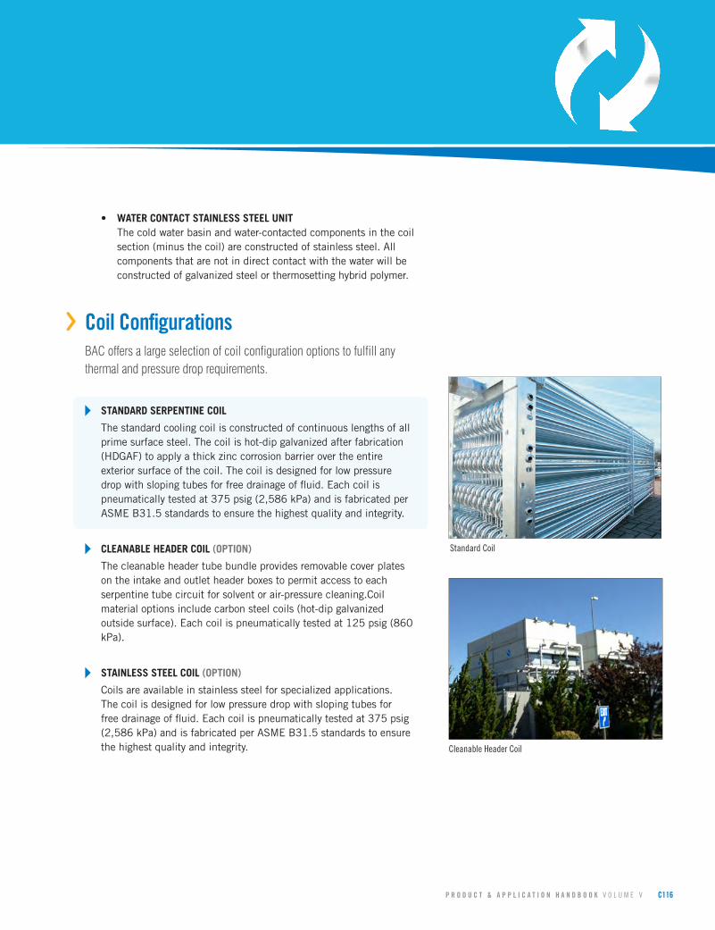
` STANDARD SERPENTINE COIL
Thestandardcoolingcoilisconstructedofcontinuouslengthsofallprimesurfacesteel.Thecoilishot-dipgalvanizedafterfabrication(HDGAF)toapplyathickzinccorrosionbarrierovertheentireexteriorsurfaceofthecoil.Thecoilisdesignedforlowpressuredropwithslopingtubesforfreedrainageoffluid.Eachcoilispneumaticallytestedat375psig(2,586kPa)andisfabricatedperASMEB31.5standardstoensurethehighestqualityandintegrity.
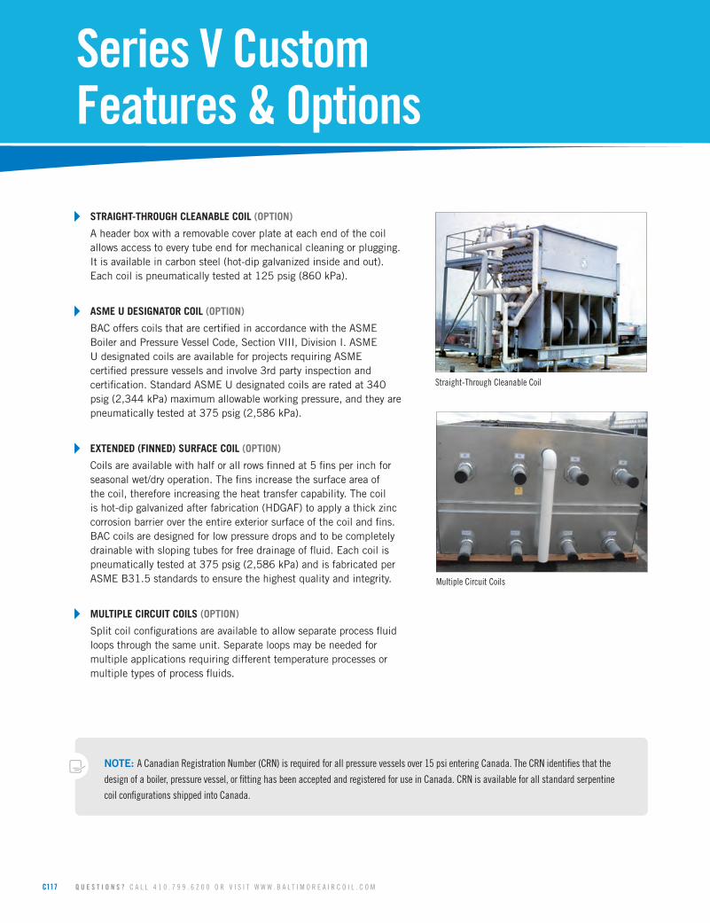
` CLEANABLE HEADER COIL (OPTION)
Thecleanableheadertubebundleprovidesremovablecoverplatesontheintakeandoutletheaderboxestopermitaccesstoeachserpentinetubecircuitforsolventorair-pressurecleaning.Coilmaterialoptionsincludecarbonsteelcoils(hot-dipgalvanizedoutsidesurface).Eachcoilispneumaticallytestedat125psig(860kPa).
` STAINLESS STEEL COIL (OPTION)
Coilsareavailableinstainlesssteelforspecializedapplications.Thecoilisdesignedforlowpressuredropwithslopingtubesforfreedrainageoffluid.Eachcoilispneumaticallytestedat375psig(2,586kPa)andisfabricatedperASMEB31.5standardstoensurethehighestqualityandintegrity.
Standard Coil
Cleanable Header Coil
Page 10
C117 Q U E S T I O N S ? C A L L 4 1 0 . 7 9 9 . 6 2 0 0 O R V I S I T W W W . B A L T I M O R E A I R C O I L . C O M
` STRAIGHT-THROUGH CLEANABLE COIL (OPTION)
Aheaderboxwitharemovablecoverplateateachendofthecoilallowsaccesstoeverytubeendformechanicalcleaningorplugging.Itisavailableincarbonsteel(hot-dipgalvanizedinsideandout).Eachcoilispneumaticallytestedat125psig(860kPa).
` ASME U DESIGNATOR COIL (OPTION)
BACofferscoilsthatarecertifiedinaccordancewiththeASMEBoilerandPressureVesselCode,SectionVIII,DivisionI.ASMEUdesignatedcoilsareavailableforprojectsrequiringASMEcertifiedpressurevesselsandinvolve3rdpartyinspectionandcertification.StandardASMEUdesignatedcoilsareratedat340psig(2,344kPa)maximumallowableworkingpressure,andtheyarepneumaticallytestedat375psig(2,586kPa).
` EXTENDED (FINNED) SURFACE COIL (OPTION)
Coilsareavailablewithhalforallrowsfinnedat5finsperinchforseasonalwet/dryoperation.Thefinsincreasethesurfaceareaofthecoil,thereforeincreasingtheheattransfercapability.Thecoilishot-dipgalvanizedafterfabrication(HDGAF)toapplyathickzinccorrosionbarrierovertheentireexteriorsurfaceofthecoilandfins.BACcoilsaredesignedforlowpressuredropsandtobecompletelydrainablewithslopingtubesforfreedrainageoffluid.Eachcoilispneumaticallytestedat375psig(2,586kPa)andisfabricatedperASMEB31.5standardstoensurethehighestqualityandintegrity.
` MULTIPLE CIRCUIT COILS (OPTION)
Splitcoilconfigurationsareavailabletoallowseparateprocessfluidloopsthroughthesameunit.Separateloopsmaybeneededformultipleapplicationsrequiringdifferenttemperatureprocessesormultipletypesofprocessfluids.
NOTE: A Canadian Registration Number (CRN) is required for all pressure vessels over 15 psi entering Canada. The CRN identifies that the
design of a boiler, pressure vessel, or fitting has been accepted and registered for use in Canada. CRN is available for all standard serpentine
coil configurations shipped into Canada.
Series V Custom Features & Options
Straight-Through Cleanable Coil
Multiple Circuit Coils
Page 11
P R O D U C T & A P P L I C A T I O N H A N D B O O K V O L U M E V C118
› Drive System OptionsThe fan drive system provides the cooling air necessary to reject unwanted heat from the system to the atmosphere. All BAC drive systems use premium efficient cooling tower duty motors and include BAC’s comprehensive 5-year motor and drive warranty. Cooling tower duty motors are specially designed for the harsh environment of a cooling tower and have permanently lubricated bearings, drastically decreasing the maintenance requirement of the motor. BAC belt drive systems are the most durable and maintenance friendly drive systems on the market, including single nut adjustment for belt tensioning to make belt tensioning simple.
` EXTERNAL V-BELT DRIVE
ThisBACengineeredexternaldriveconsistsofcentrifugalfan(s),motor(s),anddrivesystem(s)locatedoutsideofthedischargeairstream,protectingthemfrommoisture,condensation,andicing.Thedrivesystemconsistsofaspeciallydesignedbelts,taperlocksheaves,andpremiumefficientcoolingtowerdutymotortoprovidemaximumperformance.
` BALTIGUARD™ FAN SYSTEM (OPTION)
TheBALTIGUARD™FanSystemconsistsoftwostandardsingle-speedfanmotoranddriveassemblies.Onedriveassemblyissizedforfullspeedandload,andtheotherissizedapproximately2/3speedandconsumesonly1/3thedesignhorsepower.Thisconfigurationallowsthereservecapacityofastandbymotorintheeventoffailure.Asaminimum,approximately70%capacitywillbeavailablefromthelowhorsepowermotor,evenonadesignwet-bulbday.Controlsandwiringarethesameasthoserequiredforatwo-speed,two-windingmotor.RedundantmotorsareavailablebyincreasingthesizeofthestandbyfanmotoroftheBALTIGUARD™FanSystemtothesizeofthemainmotor,providing100%motorredundancy.Applicabilitydependantonmotorsizeandmodel,contactyourlocalBACRepresentativeformoreinformation.
Cust
omer
Valu
edCu
stom
er
Valu
ed
BALTIGUARD™ Fan System
External V-belt Drive
5YEAR
• WARRANTY •
BAC
MOTOR & DRIVE
Page 12
C119 Q U E S T I O N S ? C A L L 4 1 0 . 7 9 9 . 6 2 0 0 O R V I S I T W W W . B A L T I M O R E A I R C O I L . C O M
` BALTIGUARD PLUS™ FAN SYSTEM (OPTION)
TheBALTIGUARDPLUS™FanSystembuildsontheadvantagesoftheBALTIGUARD™FanSystembyaddingaVFDtoeithertheponyorthemainmotor,dependingonsystemrequirements.Thisoffersthebenefitsofadditionalcapacitycontrolandenergysavings,alongwiththeredundancyofferedbytheBALTIGUARD™FanSystem.Alternatively,aVFDcanbeaddedtoBOTHtheponyandmainmotorforcompletecapacitycontrolandredundancyunderanyload.
` VIBRATION CUTOUT SWITCH (OPTION)
Afactorymountedvibrationcutoutswitchisavailabletoeffectivelyprotectagainstrotatingequipmentfailure.BACcanprovideeitheramechanicalorsolid-stateelectronicvibrationcutoutswitchinaNEMA4enclosuretoensurereliableprotection.Additionalcontactscanbeprovidedoneitherswitchtypetoactivateanalarm.Remoteresetcapabilityisalsoavailableoneitherswitchtype.
` EXTENDED LUBRICATION LINES (OPTION)
Extendedlubricationlinesareavailableforlubricationofthefanshaftbearings.Fittingsarelocatedontheexteriorcasingpanelnearthefanhousing
› Cold Water BasinThe spray water collects in the cold water basin which is pumped back over the heat transfer coil. The Series V cold water basin includes the “V” sloped cold water basin design. During operation, this design helps eliminate any stagnant water zones, which are susceptible to biological growth.
` STANDARD MECHANICAL WATER LEVEL CONTROL
Mechanicalmake-upvalvesmustoperatecontinuouslyinthemoistandturbulentenvironmentexistingwithinevaporativecoolingequipment.Duetothisenvironment,theoperationofthevalvemustbesimple,andthevalvemustbedurable.BAC’shighqualitymechanicalwaterlevelcontrolassemblyisstandardwithallunits,andhasbeenspeciallydesignedtoprovidethemostreliableoperationwhilebeingeasytomaintain.Thisaccessoryisomittedforremotesumpapplications.
Series V Custom Features & Options
Mechanical Water Level Control Inspection
Variable Frequency Drive
Page 13
P R O D U C T & A P P L I C A T I O N H A N D B O O K V O L U M E V C120
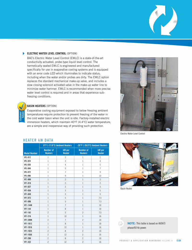
` ELECTRIC WATER LEVEL CONTROL (OPTION)
BAC’sElectricWaterLevelControl(EWLC)isastate-of-the-artconductivityactuated,probetypeliquidlevelcontrol.ThehermeticallysealedEWLCisengineeredandmanufacturedspecificallyforuseinevaporativecoolingsystemsandisequippedwithanerrorcodeLEDwhichilluminatestoindicatestatus,includingwhenthewaterand/orprobesaredirty.TheEWLCoptionreplacesthestandardmechanicalmake-upvalve,andincludesaslowclosingsolenoidactivatedvalveinthemake-upwaterlinetominimizewaterhammer.EWLCisrecommendedwhenmoreprecisewaterlevelcontrolisrequiredandinareasthatexperiencesub-freezingconditions.
` BASIN HEATERS (OPTION)
Evaporativecoolingequipmentexposedtobelowfreezingambienttemperaturesrequireprotectiontopreventfreezingofthewaterinthecoldwaterbasinwhentheunitisidle.Factory-installedelectricimmersionheaters,whichmaintain40°F(4.4°C)watertemperature,areasimpleandinexpensivewayofprovidingsuchprotection.
Model Number
0°F (-17.8°C) Ambient Heaters -20°F (-28.9°C) Ambient Heaters
Number of Heaters
kW per Heater
Number of Heaters
kW per Heater
VFL-012 1 2 1 2
VFL-024 1 3 1 4
VFL-036 1 4 1 5
VFL-048 1 5 1 7
VFL-072 1 7 1 9
VFL-096 1 9 1 12
VF1-009 1 2 1 2
VF1-018 1 2 1 2
VF1-027 1 2 1 3
VF1-036 1 3 1 5
VF1-048 1 3 1 5
VF1-072 1 5 1 7.5
VF1-096 1 5 1 7.5
VF1-144N 1 7 1 10
VF1-144 1 8 1 10
VF1-192 2 5 2 7.5
VF1-216 1 12 1 16
VF1-288N 2 7 2 10
VF1-1012 1 8 1 10
VF1-1018 1 12 1 16
VF1-1024 2 8 2 10
VF1-1036 2 12 2 16
VF1-288 2 8 2 10
VF1-432 2 12 2 16
H E A T E R k W D A T A
NOTE: This table is based on 460V/3
phase/60 Hz power.
Electric Water Level Control
Basin Heater
Cust
omer
Valu
ed
Page 14
C121 Q U E S T I O N S ? C A L L 4 1 0 . 7 9 9 . 6 2 0 0 O R V I S I T W W W . B A L T I M O R E A I R C O I L . C O M
Series V Custom Features & Options
` BASIN SWEEPER PIPING (OPTION)
Basinsweeperpipingisaneffectivemethodofreducingsedimentthatmaycollectinthecoldwaterbasinoftheunit.Acompletepipingsystem,includingnozzles,isprovidedinthecoldwaterbasintoconnecttosidestreamfiltrationequipment(providedbyothers).Formoreinformationonfiltrationsystems,consult“FiltrationGuide”foundonpage J241.VF1-009through048areprovidedwithfilterconnectiononlysincetheturbulenceinthecoldwaterbasinkeepsparticlesinsuspension.
` LOW AND HIGH LEVEL ALARM FLOAT SWITCHES (OPTION)
Lowandhighlevelalarmfloatswitchesareavailabletoprovideaddedcontroltoyourequipmentoperation.Levelalarmscanalertoperatorstoanabnormaloperatingconditiontoensurethehighestsystemefficiencywithminimalwaterusage.
› Water Distribution SystemThe Series V water distribution system is provided with BAC 360™ Spray Nozzles. These nozzles are large orifice and non-clogging.
` STANDARD SPRAY WATER PUMP
TheSeriesVisprovidedwithanintegralspraywaterpumpsizedtodistributetherecirculatingwateroverthecoilmaximizingcapacity.ThepatentedBAC360™non-clognozzlesensureevenflowoverthecoilareaandaresimpletoremoveformaintenance.
` REDUNDANT PUMPS (OPTION)
Anoptionalsecondaryspraypumpisavailableforcriticalapplications.
› Shipping and RiggingBAC units are factory-assembled to ensure uniform quality with minimum field assembly. Each unit has been designed with rigging and assembly in mind and includes features to minimize the number of tools required and installation time. All Low Profile units ship completely assembled, minimizing installation time and cost. There are no motors to mount, no sheaves to align, no belts to install, and no make-up system to assemble.
Standard Spray Water Pump
Single Piece Lift of a VFL
Page 15
P R O D U C T & A P P L I C A T I O N H A N D B O O K V O L U M E V C122
` KNOCKDOWN UNITS (OPTION)
Knockdownunitsareavailableforjobswhereaccesstothecoolingtowerlocationislimitedbyelevators,doorways,orsimilarobstacles,whereliftingmethodsimposeverystrictweightlimits,orwheretheshippingcostofafullyassembledtowerisexcessive.Allmaterialsofconstructionanddesignfeaturesarethesameasthoseofafactoryassembledunit.
› Sound OptionsThe low sound levels generated by Series V Closed Circuit Cooling Towers make them suitable for most installations. The panel opposite the air intake, called the blankoff panel, is inherently quiet. Positioning the blankoff panel towards the sound sensitive direction insulates sensitive areas from higher sound levels.
` STANDARD FAN
ThestandardcentrifugalfanprovidedonSeriesVClosedCircuitCoolingTowersisinherentlyquietandisselectedtooptimizelowsoundlevels.
` SOUND ATTENUATION (OPTION)
Forextremelysoundsensitiveinstallations,factorydesigned,tested,andratedsoundattenuationoptionsareavailableforboththeairintakeanddischarge.ConsultyourlocalBACRepresentativeregardingavailableoptions.
` SINGLE-SIDE AIR INTAKE
Single-sideairintakeunitscanbeplacedclosetosolidwalls,reducingthesizeofenclosuresandallowingformoreprofitableuseofpremiumspace.Also,thepaneloppositetheairintake,calledtheblankoffpanel,isinherentlyquiet.Positioningtheblankoffpaneltowardsthesoundsensitivedirectioninsulatessensitiveareasfromhighersoundlevels.
Intake and Discharge Sound Attenuation
Cust
omer
Valu
ed
Standard Centrifugal Fan
Page 16
C123 Q U E S T I O N S ? C A L L 4 1 0 . 7 9 9 . 6 2 0 0 O R V I S I T W W W . B A L T I M O R E A I R C O I L . C O M
› Air Intake OptionsIn a closed circuit cooling tower, airborne debris can be entrained in the water through the unit’s air intake. The Series V has several options for air intake accessories that prevent debris from entering the system and maintain even unobstructed flow through the unit. Reducing the amount of debris that enters the tower lowers maintenance requirements and helps to maintain thermal efficiency.
` AIR INTAKE SCREENS
Thestandard1”x1”wirescreenisfactory-installedovertheairintaketopreventdebrisfromenteringthetower.
` BOTTOM INTAKE SCREENS (OPTION)
SeriesVClosedCircuitCoolingTowersareavailablewithfactory-installedwiremeshscreensoverthebottomopeningstopreventunauthorizedaccess.
` SOLID BOTTOM PANELS (OPTION)
Factory-installedbottompanelsarerequiredwhenintakeairisductedtotheunit.
› Air Discharge OptionsBAC offers a full line of discharge hoods that are built, tested, and rated specifically for all Series V Closed Circuit Cooling Towers.
` PCD HOODS AND INSULATION (OPTION)
TheinnovativedesignofBACClosedCircuitCoolingTower’sresultsinalowheatlosswhentheunitisidle.Whenadditionalheatlosspreventionisdesired,factorymountedPCDswithstainlesssteellinkagesanddamperactuatorscanbeprovided.Themotoractuatorsareeasilyaccessible.Theadditionoffactorymountedinsulationtothehoodand/orcasingfurtherreducestheheatlossbyminimizinglossesduetoconduction.PerASHRAE90.1-2010eitheranautomatic3wayvalveorPCDsarerequiredonClosedCircuitCoolingTowersusedonheatpumpapplicationswhenusedinheatingmode.
Series V Custom Features & Options
Tapered Hood
Multiple Cell Layout
Page 17
P R O D U C T & A P P L I C A T I O N H A N D B O O K V O L U M E V C124
` DISCHARGE HOODS (OPTION)
BACoffersafulllineofdischargehoodswithandwithoutpositiveclosuredampersthatarebuilt,tested,andratedspecificallyforallSeriesVClosedCircuitCoolingTowers.Thetaperedhoodsaredesignedtoincreasethedischargeairvelocitytoavoidrecirculationinextremelytightenclosures.Straightortaperedhoodscanbeusedtoelevatetheunitdischargeaboveadjacentwalls.Alargerfanmotormaybenecessarywhenthisoptionisprovided.
› Access OptionsBAC’s evaporative equipment is designed to be the most easily maintained for sustaining capacity over a longer life. All access options are OSHA compliant to ensure personnel safety and code compliance.
` HANDRAIL PACKAGES AND LADDERS (OPTION)
Handrailpackagesandladdersareavailabletoprovidesafeaccesstothetopoftheunitformaintenancetothedistributionsystem.Galvanizedsteeleliminatorsprovideasafewalkingsurfaceontopoftheunit.
NOTE: Platforms, ladders, handrails, safety gates, and safety cages can be added at
the time of order or as an aftermarket item.
Discharge Hood
Ladder and Handrail Package
Page 18
C125 Q U E S T I O N S ? C A L L 4 1 0 . 7 9 9 . 6 2 0 0 O R V I S I T W W W . B A L T I M O R E A I R C O I L . C O M
Series V Engineering Data
Fluid In
Fluid Out
1/2” FPT Vent
1” Make-up Overflow
4’-1 1/4”
F
L2” Drain
Spray Pump
AccessDoor
H
Fluid In
Fluid Out
1/2” FPT Vent
2” Make-up
Overflow
7’-10 1/2”
FH
L
2” Drain
AccessDoor
End Elevation: Models VFL-012 to 048 Side Elevation: Models VFL-012 to 048
Side Elevation: Models VFL-072 to 096End Elevation: Models VFL-072 to 096
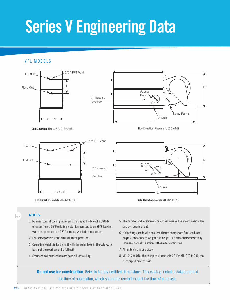
V F L M O D E L S
NOTES:
1. Nominal tons of cooling represents the capability to cool 3 USGPM
of water from a 95°F entering water temperature to an 85°F leaving
water temperature at a 78°F entering wet-bulb temperature.
2. Fan horsepower is at 0” external static pressure.
3. Operating weight is for the unit with the water level in the cold water
basin at the overflow and a full coil.
4. Standard coil connections are beveled for welding.
5. The number and location of coil connections will vary with design flow
and coil arrangement.
6. If discharge hoods with positive closure damper are furnished, see
page C135 for added weight and height. Fan motor horsepower may
increase; consult selection software for verification.
7. All units ship in one piece.
8. VFL-012 to 048, the riser pipe diameter is 3”. For VFL-072 to 096, the
riser pipe diameter is 4”.
Do not use for construction. Refer to factory certified dimensions. This catalog includes data current at
the time of publication, which should be reconfirmed at the time of purchase.
Page 19
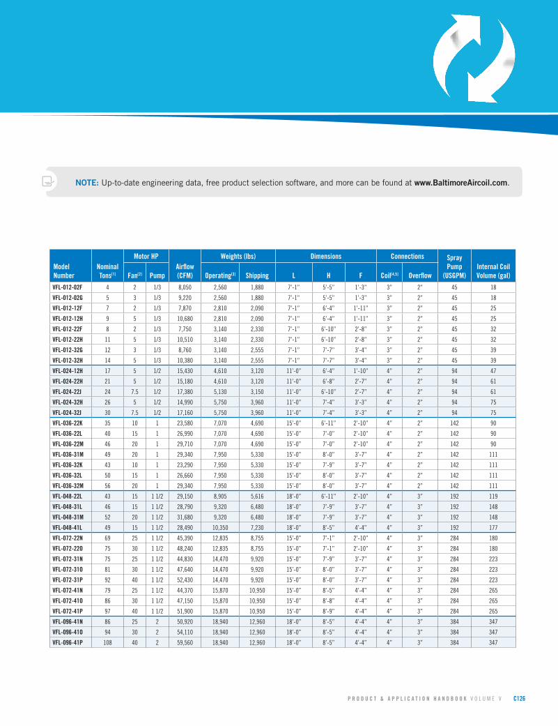
P R O D U C T & A P P L I C A T I O N H A N D B O O K V O L U M E V C126
Model Number
Nominal Tons[1]
Motor HPAirflow (CFM)
Weights (lbs) Dimensions Connections Spray Pump
(USGPM)Internal Coil Volume (gal)Fan[2] Pump Operating[3] Shipping L H F Coil[4,5] Overflow
VFL-012-02F 4 2 1/3 8,050 2,560 1,880 7’-1” 5’-5” 1’-3” 3” 2” 45 18
VFL-012-02G 5 3 1/3 9,220 2,560 1,880 7’-1” 5’-5” 1’-3” 3” 2” 45 18
VFL-012-12F 7 2 1/3 7,870 2,810 2,090 7’-1” 6’-4” 1’-11” 3” 2” 45 25
VFL-012-12H 9 5 1/3 10,680 2,810 2,090 7’-1” 6’-4” 1’-11” 3” 2” 45 25
VFL-012-22F 8 2 1/3 7,750 3,140 2,330 7’-1” 6’-10” 2’-8” 3” 2” 45 32
VFL-012-22H 11 5 1/3 10,510 3,140 2,330 7’-1” 6’-10” 2’-8” 3” 2” 45 32
VFL-012-32G 12 3 1/3 8,760 3,140 2,555 7’-1” 7’-7” 3’-4” 3” 2” 45 39
VFL-012-32H 14 5 1/3 10,380 3,140 2,555 7’-1” 7’-7” 3’-4” 3” 2” 45 39
VFL-024-12H 17 5 1/2 15,430 4,610 3,120 11’-0” 6’-4” 1’-10” 4” 2” 94 47
VFL-024-22H 21 5 1/2 15,180 4,610 3,120 11’-0” 6’-8” 2’-7” 4” 2” 94 61
VFL-024-22J 24 7.5 1/2 17,380 5,130 3,150 11’-0” 6’-10” 2’-7” 4” 2” 94 61
VFL-024-32H 26 5 1/2 14,990 5,750 3,960 11’-0” 7’-4” 3’-3” 4” 2” 94 75
VFL-024-32J 30 7.5 1/2 17,160 5,750 3,960 11’-0” 7’-4” 3’-3” 4” 2” 94 75
VFL-036-22K 35 10 1 23,580 7,070 4,690 15’-0” 6’-11” 2’-10” 4” 2” 142 90
VFL-036-22L 40 15 1 26,990 7,070 4,690 15’-0” 7’-0” 2’-10” 4” 2” 142 90
VFL-036-22M 46 20 1 29,710 7,070 4,690 15’-0” 7’-0” 2’-10” 4” 2” 142 90
VFL-036-31M 49 20 1 29,340 7,950 5,330 15’-0” 8’-0” 3’-7” 4” 2” 142 111
VFL-036-32K 43 10 1 23,290 7,950 5,330 15’-0” 7’-9” 3’-7” 4” 2” 142 111
VFL-036-32L 50 15 1 26,660 7,950 5,330 15’-0” 8’-0” 3’-7” 4” 2” 142 111
VFL-036-32M 56 20 1 29,340 7,950 5,330 15’-0” 8’-0” 3’-7” 4” 2” 142 111
VFL-048-22L 43 15 1 1/2 29,150 8,905 5,616 18’-0” 6’-11” 2’-10” 4” 3” 192 119
VFL-048-31L 46 15 1 1/2 28,790 9,320 6,480 18’-0” 7’-9” 3’-7” 4” 3” 192 148
VFL-048-31M 52 20 1 1/2 31,680 9,320 6,480 18’-0” 7’-9” 3’-7” 4” 3” 192 148
VFL-048-41L 49 15 1 1/2 28,490 10,350 7,230 18’-0” 8’-5” 4’-4” 4” 3” 192 177
VFL-072-22N 69 25 1 1/2 45,390 12,835 8,755 15’-0” 7’-1” 2’-10” 4” 3” 284 180
VFL-072-22O 75 30 1 1/2 48,240 12,835 8,755 15’-0” 7’-1” 2’-10” 4” 3” 284 180
VFL-072-31N 75 25 1 1/2 44,830 14,470 9,920 15’-0” 7’-9” 3’-7” 4” 3” 284 223
VFL-072-31O 81 30 1 1/2 47,640 14,470 9,920 15’-0” 8’-0” 3’-7” 4” 3” 284 223
VFL-072-31P 92 40 1 1/2 52,430 14,470 9,920 15’-0” 8’-0” 3’-7” 4” 3” 284 223
VFL-072-41N 79 25 1 1/2 44,370 15,870 10,950 15’-0” 8’-5” 4’-4” 4” 3” 284 265
VFL-072-41O 86 30 1 1/2 47,150 15,870 10,950 15’-0” 8’-8” 4’-4” 4” 3” 284 265
VFL-072-41P 97 40 1 1/2 51,900 15,870 10,950 15’-0” 8’-9” 4’-4” 4” 3” 284 265
VFL-096-41N 86 25 2 50,920 18,940 12,960 18’-0” 8’-5” 4’-4” 4” 3” 384 347
VFL-096-41O 94 30 2 54,110 18,940 12,960 18’-0” 8’-5” 4’-4” 4” 3” 384 347
VFL-096-41P 108 40 2 59,560 18,940 12,960 18’-0” 8’-5” 4’-4” 4” 3” 384 347
NOTE: Up-to-dateengineeringdata,freeproductselectionsoftware,andmorecanbefoundat www.BaltimoreAircoil.com.
Page 20
C127 Q U E S T I O N S ? C A L L 4 1 0 . 7 9 9 . 6 2 0 0 O R V I S I T W W W . B A L T I M O R E A I R C O I L . C O M
Series V Engineering Data
Fluid In
Fluid out
1/2” FPT Vent
2” Drain
2” Overflow
1” Make-up
3’ 11-1/2” L
AM
F
H
L
M
1/2” FPT VentFluid In
Fluid Out
Access1” Make-up
3” Overflow
2” Drain
4’- 8 5/8”
H
F
M
L
Fluid In
Fluid Out
1/2” MPT Vent
2” Make-up
3” Overflow
Access
7’ - 10 3/8”
F
H
A
Side Elevation: Models VF1-009 to 036End Elevation: Models VF1-009 to 036
Side Elevation: Models VF1-072
Side Elevation: Models VF1-048
End Elevation: Models VF1-072
End Elevation: Models VF1-048
V F 1 M O D E L S
NOTES FOR OPPOSITE TABLE:
1. Nominal tons of cooling represents the capability to cool 3 USGPM
of water from a 95°F entering water temperature to an 85°F leaving
water temperature at a 78°F entering wet-bulb temperature.
2. Fan horsepower is at 0” external static pressure.
3. Operating weight is for the unit with the water level in the cold water
basin at the overflow and a full coil.
4. Units marked with an asterisk ship in one piece. The coil section is the
heaviest section.
5. Standard coil connections are beveled for welding.
6. The number and location of coil connections will vary with design flow
and coil arrangement.
7. If discharge hoods with positive closure damper are furnished, see
page C135 for added weight and height. Fan motor horsepower may
increase; consult selection software for verification.
8. For VF1-009 to 048, the riser pipe diameter is 3”. For VF1-072 the
riser pipe diameter is 4”.
Do not use for construction. Refer to factory certified dimensions. This catalog includes data current at
the time of publication, which should be reconfirmed at the time of purchase.
Page 21
P R O D U C T & A P P L I C A T I O N H A N D B O O K V O L U M E V C128
NOTE: Up-to-dateengineeringdata,freeproductselectionsoftware,andmorecanbefoundat www.BaltimoreAircoil.com.
Model Number
Nominal Tons[1]
Motor HP
Airflow (CFM)
Weights (lbs) Dimensions Connections Spray Pump
(USGPM)
Internal Coil Volume
(gal)Fan[2] Pump Operating[3] ShippingHeaviest Section[4] L H F A Coil[5,6] Overflow
VF1-009-12E 4 1.5
1/3
4,510 1,875 1,625 1,460*
3’-0”
7’-4” 1’-11”
3’-9” 3” 2” 35
20VF1-009-12F 5 2 4,970 1,875 1,625 1,460* 7’-4” 1’-11” 20VF1-009-12G 5 3 5,690 1,875 1,625 1,460* 7’-4” 1’-11” 20VF1-009-22F 6 2 4,890 2,075 1,785 1,000 8’-1” 2’-8” 26VF1-009-22G 7 3 5,590 2,075 1,785 1,000 8’-1” 2’-8” 26VF1-009-32G 8 3 5,520 2,295 1,965 1,180 8’-9” 3’-4” 31VF1-009-42G 9 3 5,470 2,495 2,125 1,340 9’-6” 4’-1” 36VF1-018-12F 9 2
1/2
8,050 2,955 2,415 2,415*
6’-0”
7’-4” 1’-11”
3’-9” 4” 2” 75
38VF1-018-12G 11 3 9,220 2,955 2,415 2,415* 7’-4” 1’-11” 38VF1-018-12H 14 5 10,930 2,955 2,415 2,415* 7’-4” 1’-11” 38VF1-018-22H 17 5 10,750 3,260 2,640 1,720 8’-1” 2’-8” 49VF1-018-22J 20 7.5 12,310 3,260 2,640 1,720 8’-1” 2’-8” 49VF1-018-32G 16 3 8,960 3,660 2,940 2,010 8’-9” 3’-3” 60VF1-018-32H 19 5 10,620 3,660 2,940 2,010 8’-9” 3’-3” 60VF1-018-32J 22 7.5 12,150 3,660 2,940 2,010 8’-9” 3’-3” 60VF1-018-42H 21 5 10,510 4,010 3,190 2,260 9’-6” 4’-0” 71VF1-018-42J 24 7.5 12,030 4,010 3,190 2,260 9’-6” 4’-0” 71VF1-027-22H 24 5
3/4
14,060 4,860 3,750 2,470
9’-0”
8’-4” 2’-10”
3’-9” 4” 2” 115
72VF1-027-22J 28 7.5 16,090 4,860 3,750 2,470 8’-4” 2’-10” 72VF1-027-22K 32 10 17,710 4,860 3,750 2,470 8’-4” 2’-10” 72VF1-027-32H 26 5 13,880 5,440 4,180 2,850 9’-1” 3’-7” 89VF1-027-32J 31 7.5 15,890 5,440 4,180 2,850 9’-1” 3’-7” 89VF1-027-32K 35 10 17,490 5,440 4,180 2,850 9’-1” 3’-7” 89VF1-027-42H 28 5 13,740 5,970 4,570 3,240 9’-10” 4’-4” 106VF1-027-42J 33 7.5 15,730 5,970 4,570 3,240 9’-10” 4’-4” 106VF1-027-42K 37 10 17,310 5,970 4,570 3,240 9’-10” 4’-4” 106VF1-036-21L 41 15
1
24,870 6,280 4,760 3,200
12’-0”
8’-4” 2’-10”
3’-9” 4” 2” 150
95VF1-036-22J 35 7.5 19,740 6,280 4,760 3,200 8’-4” 2’-10” 95VF1-036-22K 39 10 21,730 6,280 4,760 3,200 8’-4” 2’-10” 95VF1-036-22L 47 15 24,870 6,280 4,760 3,200 8’-4” 2’-10” 95VF1-036-31L 44 15 24,560 7,020 5,310 3,720 9’-1” 3’-7” 118VF1-036-32J 37 7.5 19,490 7,020 5,310 3,720 9’-1” 3’-7” 118VF1-036-41L 47 15 24,310 7,710 5,810 4,220 9’-10” 4’-4” 140VF1-036-51L 49 15 24,100 8,390 6,310 4,720 10’-7” 4’-4” 163VF1-048-21L 48 15
1 1/2
32,520 10,230 7,870 4,920
12’-0”
10’-0” 2’-10”
5’-5” 4” 3” 220
137VF1-048-21M 55 20 35,790 10,230 7,870 4,920 10’-0” 2’-10” 137VF1-048-31M 59 20 35,340 11,390 8,460 5,930 10’-9” 3’-7” 170VF1-048-31N 65 25 38,070 11,390 8,460 5,930 10’-9” 3’-7” 170VF1-048-41M 63 20 34,980 12,690 9,320 6,600 11’-7” 4’-4” 203VF1-048-41N 70 25 37,690 12,690 9,320 6,600 11’-7” 4’-4” 203VF1-072-21M 62 20
2
45,990 15,670 10,720 6,580
11’-8”
11’-4” 2’-10”
6’-9” 4” 3” 305
190VF1-072-21N 69 25 49,540 15,670 10,720 6,580 11’-4” 2’-10” 190VF1-072-21O 75 30 52,650 15,670 10,720 6,580 11’-4” 2’-10” 190VF1-072-31M 67 20 45,420 17,380 12,050 7,950 12’-2” 3’-7” 235VF1-072-31N 74 25 48,930 17,380 12,050 7,950 12’-2” 3’-7” 235VF1-072-31O 81 30 51,990 17,380 12,050 7,950 12’-2” 3’-7” 235VF1-072-41M 72 20 44,960 18,000 12,480 9,320 12’-11” 4’-4” 281VF1-072-41N 80 25 48,430 18,000 12,480 9,320 12’-11” 4’-4” 281VF1-072-41O 86 30 51,460 18,000 12,480 9,320 12’-11” 4’-4” 281
Side Elevation: Models VF1-009 to 036
Side Elevation: Models VF1-072
Side Elevation: Models VF1-048
Page 22
C129 Q U E S T I O N S ? C A L L 4 1 0 . 7 9 9 . 6 2 0 0 O R V I S I T W W W . B A L T I M O R E A I R C O I L . C O M
Series V Engineering Data
NOTE: Up-to-dateengineeringdata,freeproductselectionsoftware,andmorecanbefoundat www.BaltimoreAircoil.com.
Fluid In
Fluid Out
1/2” FPT Vent
2” Make-up
3” Overflow
7’ 10-3/8”
F
H
A
L
M
11’-11 3/4”
24’-0 1/2”
L
M
L
M M MMM
36’-1 1/4”18’-0 1/8”
Side Elevation: Models VF1-192N & 288N
Side Elevation: Models VF1-096 & 144NEnd Elevation: Models VF1-096 to 144N, & VF1-192 to 288N
V F 1 M O D E L S
Fluid In
Fluid Out
1/2” FPT Vent
2” Make-up
3” Overflow
7’ 10-3/8”
F
H
A
L
M
Page 23
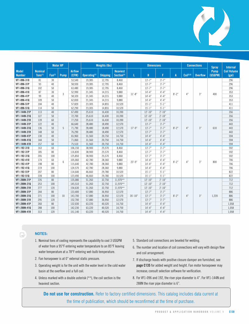
P R O D U C T & A P P L I C A T I O N H A N D B O O K V O L U M E V C130
Model Number
Nominal Tons[1]
Motor HP
Airflow (CFM)
Weights (lbs) Dimensions Connections Spray Pump
(USGPM)
Internal Coil Volume
(gal)Fan[2] Pump Operating[3] ShippingHeaviest Section[4] L H F A Coil[5,6] Overflow
VF1-096-31O 81 30
3
53,540 19,385 12,795 8,460
11’-8”
13’-7” 3’-7”
8’-2” 4” 3” 400
296VF1-096-31P 93 40 58,930 19,385 12,795 8,460 13’-7” 3’-7” 296VF1-096-31Q 102 50 63,480 19,385 12,795 8,460 13’-7” 3’-7” 296VF1-096-41O 87 30 52,990 21,345 14,215 9,880 14’-4” 4’-4” 353VF1-096-41P 99 40 58,320 21,345 14,215 9,880 14’-4” 4’-4” 353VF1-096-41Q 109 50 62,830 21,345 14,215 9,880 14’-4” 4’-4” 353VF1-096-51P 104 40 57,820 23,305 14,855 10,520 15’-1” 5’-1” 411VF1-096-51Q 114 50 62,290 23,305 14,855 10,520 15’-1” 5’-1” 411VF1-144N-21P 113 40
5
67,490 25,610 16,430 10,390
17’-9”
12’-10” 2’-10”
8’-2” 4” 3” 610
356VF1-144N-21Q 127 50 72,700 25,610 16,430 10,390 12’-10” 2’-10” 356VF1-144N-21R 139 60 77,250 25,610 16,430 10,390 12’-10” 2’-10” 356VF1-144N-31P 122 40 66,640 28,480 18,490 12,570 13’-7” 3’-7” 443VF1-144N-31Q 136 50 71,790 28,480 18,490 12,570 13’-7” 3’-7” 443VF1-144N-31R 148 60 76,290 28,480 18,490 12,570 13’-7” 3’-7” 443VF1-144N-41P 130 40 65,960 31,560 20,750 14,750 14’-4” 4’-4” 594VF1-144N-41Q 144 50 71,060 31,560 20,750 14,750 14’-4” 4’-4” 594VF1-144N-41R 157 60 75,510 31,560 20,750 14,750 14’-4” 4’-4” 594VF1-192-31O 163 60
6
106,150 38,900 25,570 8,460
23’-9”
13’-7” 3’-7”
8’-2” 4” 3” 800
592VF1-192-31P 185 80 116,830 38,900 25,570 8,460 13’-7” 3’-7” 592VF1-192-31Q 205 100 125,850 38,900 25,570 8,460 13’-7” 3’-7” 592VF1-192-41O 174 60 105,060 42,780 28,360 9,880 14’-4” 4’-4” 706VF1-192-41P 198 80 115,640 42,780 28,360 9,880 14’-4” 4’-4” 706VF1-192-41Q 219 100 124,570 42,780 28,360 9,880 14’-4” 4’-4” 706VF1-192-51P 207 80 114,640 46,660 29,780 10,520 15’-1” 5’-1” 822VF1-192-51Q 228 100 123,490 46,660 29,780 10,520 15’-1” 5’-1” 822VF1-288N-21P 226 80
10
135,080 51,260 32,750 11,970**
35’-10”
12’-10” 2’-10”
8’-2” 4” 3” 1,220
712VF1-288N-21Q 253 100 145,510 51,260 32,750 11,970** 12’-10” 2’-10” 712VF1-288N-21R 277 120 154,630 51,260 32,750 11,970** 12’-10” 2’-10” 712VF1-288N-31P 244 80 133,400 57,080 36,950 12,570 13’-7” 3’-7” 886VF1-288N-31Q 271 100 143,700 57,080 36,950 12,570 13’-7” 3’-7” 886VF1-288N-31R 295 120 152,700 57,080 36,950 12,570 13’-7” 3’-7” 886VF1-288N-41P 260 80 132,030 63,220 40,520 14,750 14’-4” 4’-4” 1,058VF1-288N-41Q 288 100 142,230 63,220 40,520 14,750 14’-4” 4’-4” 1,058VF1-288N-41R 313 120 151,140 63,220 40,520 14,750 14’-4” 4’-4” 1,058
NOTES:
1. Nominal tons of cooling represents the capability to cool 3 USGPM
of water from a 95°F entering water temperature to an 85°F leaving
water temperature at a 78°F entering wet-bulb temperature.
2. Fan horsepower is at 0” external static pressure.
3. Operating weight is for the unit with the water level in the cold water
basin at the overflow and a full coil.
4. Unless marked with a double asterisk (**), the coil section is the
heaviest section.
5. Standard coil connections are beveled for welding.
6. The number and location of coil connections will vary with design flow
and coil arrangement.
7. If discharge hoods with positive closure damper are furnished, see
page C135 for added weight and height. Fan motor horsepower may
increase; consult selection software for verification.
8. For VF1-096 and 192, the riser pipe diameter is 4”. For VF1-144N and
288N the riser pipe diameter is 6”.
Do not use for construction. Refer to factory certified dimensions. This catalog includes data current at
the time of publication, which should be reconfirmed at the time of purchase.
Page 24
C131 Q U E S T I O N S ? C A L L 4 1 0 . 7 9 9 . 6 2 0 0 O R V I S I T W W W . B A L T I M O R E A I R C O I L . C O M
Series V Engineering Data
Side Elevation: Models VF1-1012
V F 1 M O D E L S
10 7
/8"
1/2” FTP Vent
1/1/2” Make-up
3” Overflow2” Drain
Fluid In
Fluid Out
10 7
/8"
Side Elevation: Models VF1-1018 Side Elevation: Models VF1-1024
Side Elevation: Models VF1-1036
10 7
/8"
1/2” FTP Vent
1/1/2” Make-up
3” Overflow2” Drain
Fluid In
Fluid Out
10 7
/8"
10 7
/8"
1/2” FTP Vent
1/1/2” Make-up
3” Overflow2” Drain
Fluid In
Fluid Out
10 7
/8"
10 7
/8"
1/2” FTP Vent
1/1/2” Make-up
3” Overflow2” Drain
Fluid In
Fluid Out
10 7
/8"
End Elevation: Models Models VF1-1012, 1018, 1024, 1036
Page 25
P R O D U C T & A P P L I C A T I O N H A N D B O O K V O L U M E V C132
Model Number
Nominal Tons[1]
Motor HP
Airflow (CFM)
Weights (lbs) Dimensions Connections Spray Pump
(USGPM)
Internal Coil Volume
(gal)Fan[2] Pump Operating[3] ShippingHeaviest Section[4] L H F A Coil[5,6] Overflow
VF1-1012N-4D 127 (1) 60
(1) 3
84,580 20,500 14,150 8,660
12’-0”
14'-1" 2'-10"
8’-4” 4” 3” 350
303VF1-1012N-5D 145 (1) 60 83,610 22,740 15,790 10,300 14'-10" 3'-7" 375VF1-1012N-6D 177 (1) 75 88,740 24,830 17,280 11,700 14'-11" 3'-8" 447VF1-1012N-7D 192 (1) 75 88,020 27,010 18,860 13,280 15'-6" 4'-3" 520VF1-1012N-8D 201 (1) 75 87,380 29,180 20,430 14,850 16'-2" 4'-11" 592VF1-1018N-4D 220
(2) 50 (2) 5
132,460 29,610 20,060 12,420
18’-0”
14'-1" 2'-10"
8’-4” 4” 3” 520
450VF1-1018N-5D 249 130,920 32,820 22,370 14,730 14'-10" 3'-7" 559VF1-1018N-6D 273 129,670 35,920 24,560 16,920 14'-11" 3'-8" 668VF1-1018N-7D 294 128,630 39,180 26,910 19,270 15'-6" 4'-3" 777VF1-1018N-8D 307 127,760 42,370 29,190 21,550 16'-2" 4'-11" 886VF1-1024N-4D 255 (2) 60
(2) 3
169,160 40,800 27,950 10,630
24’-3”
14'-1" 2'-10"
8’-4” 4” 3” 700
303VF1-1024N-5D 290 (2) 60 167,220 45,280 31,230 10,300 14'-10" 3'-7" 375VF1-1024N-6D 355 (2) 75 177,480 49,460 34,210 11,700 14'-11" 3'-8" 447VF1-1024N-7D 385 (2) 75 176,040 53,820 37,370 13,280 15'-6" 4'-3" 520VF1-1024N-8D 402 (2) 75 174,760 58,160 40,510 14,850 16'-2" 4'-11" 592VF1-1036N-4D 441
(4) 50 (2) 5
264,920 59,220 40,120 12,420
36’-3”
14'-1" 2'-10"
8’-4” 4” 3” 1,040
450VF1-1036N-5D 498 261,840 65,640 44,740 14,730 14'-10" 3'-7" 559VF1-1036N-6D 546 259,340 71,840 49,120 16,920 14'-11" 3'-8" 668VF1-1036N-7D 589 257,260 78,360 53,820 19,270 15'-6" 4'-3" 777VF1-1036N-8D 614 255,520 84,740 58,380 21,550 16'-2" 4'-11" 886
NOTE: Up-to-dateengineeringdata,freeproductselectionsoftware,andmorecanbefoundat www.BaltimoreAircoil.com.
AdditionalmodelsareavailableinBACselectionsoftware,includinglowerfanmotorHPmodelsforhigherefficiency,and2-passmodelsforhigherthermalperformance.
NOTES:
1. Nominal tons of cooling represents the capability to cool 3 USGPM
of water from a 95°F entering water temperature to an 85°F leaving
water temperature at a 78°F entering wet-bulb temperature.
2. Fan horsepower is at 0” external static pressure.
3. Operating weight is for the unit with the water level in the cold water
basin at the overflow and a full coil.
4. Unless marked with a double asterisk (**), the coil section is the
heaviest section.
5. Standard coil connections are beveled for welding.
6. The number and location of coil connections will vary with design flow
and coil arrangement.
7. If discharge hoods with positive closure damper are furnished, see
page C135 for added weight and height. Fan motor horsepower may
increase; consult selection software for verification.
8. The riser pipe diameter is 6”.
Do not use for construction. Refer to factory certified dimensions. This catalog includes data current at
the time of publication, which should be reconfirmed at the time of purchase.
Page 26
C133 Q U E S T I O N S ? C A L L 4 1 0 . 7 9 9 . 6 2 0 0 O R V I S I T W W W . B A L T I M O R E A I R C O I L . C O M
Series V Engineering Data
End Elevation: Models VF1-144, 216, & VF1-288 to 432
Fluid In
Fluid Out
1/2” FPT Vent
2” Make-Up3” Overflow
11’ 10”
F
H
A
L
M M2” Drain
Side Elevation: Models VF1-144
Fluid In
Fluid Out
1/2” FPT Vent
2” Make-up
3” Overflow
7’ 10-3/8”
F
H
A
L
M
Fluid In
Fluid Out
1/2” FPT Vent
2” Make-Up3” Overflow
11’ 10”
F
H
A
L
M M2” Drain
Side Elevation: Models VF1-216
11’-11 3/4”
24’-0 1/2”
L
M
L
M M MMM
36’-1 1/4”18’-0 1/8”
Side Elevation: Models VF1-288
Side Elevation: Models VF1-432
11’-11 3/4”
24’-0 1/2”
L
M
L
M M MMM
36’-1 1/4”18’-0 1/8”
Page 27
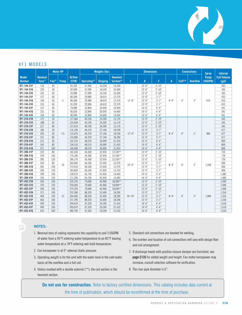
P R O D U C T & A P P L I C A T I O N H A N D B O O K V O L U M E V C134
Model Number
Nominal Tons[1]
Motor HP
Airflow (CFM)
Weights (lbs) Dimensions Connections Spray Pump
(USGPM)
Internal Coil Volume
(gal)Fan[2] Pump Operating[3] ShippingHeaviest Section[4] L H F A Coil[5,6] Overflow
VF1-144-21P 116 40
5
81,320 27,090 16,530 10,300
11’-8”
13’-0” 2’-10”
8’-4” 4” 3” 610
365VF1-144-21Q 129 50 87,600 27,090 16,530 10,300 13’-0” 2’-10” 365VF1-144-21R 141 60 93,080 27,090 16,530 10,300 13’-0” 2’-10” 365VF1-144-31P 127 40 80,300 29,980 18,610 12,370 13’-9” 3’-7” 453VF1-144-31Q 140 50 86,500 29,980 18,610 12,370 13’-9” 3’-7” 453VF1-144-31R 153 60 91,920 29,980 18,610 12,370 13’-9” 3’-7” 453VF1-144-41P 137 40 79,480 32,840 20,640 14,440 14’-6” 4’-4” 541VF1-144-41Q 151 50 85,620 32,840 20,640 14,440 14’-6” 4’-4” 541VF1-144-41R 164 60 90,990 32,840 20,640 14,440 14’-6” 4’-4” 541VF1-216-21N 172 50
7.5
117,660 40,190 24,200 15,170
17’-9”
13’-0” 2’-10”
8’-4” 4” 3” 900
545VF1-216-21O 188 60 125,030 40,190 24,200 15,170 13’-0” 2’-10” 545VF1-216-21P 217 80 137,610 40,190 24,200 15,170 13’-0” 2’-10” 545VF1-216-31N 185 50 116,190 44,370 27,140 18,290 13’-9” 3’-7” 677VF1-216-31O 202 60 123,470 44,370 27,140 18,290 13’-9” 3’-7” 677VF1-216-31P 231 80 135,890 44,370 27,140 18,290 13’-9” 3’-7” 677VF1-216-41O 215 60 122,210 48,570 30,090 21,410 14’-6” 4’-4” 809VF1-216-41P 245 80 134,510 48,570 30,090 21,410 14’-6” 4’-4” 809VF1-216-41Q 271 100 144,900 48,570 30,090 21,410 14’-6” 4’-4” 809VF1-288-21P 232 80
10
162,630 54,300 32,930 12,330**
23’-9”
13’-0” 2’-10”
8’-4” 4” 3” 1,240
730VF1-288-21Q 259 100 175,190 54,300 32,930 12,330** 13’-0” 2’-10” 730VF1-288-21R 282 120 186,170 54,300 32,930 12,330** 13’-0” 2’-10” 730VF1-288-31P 254 80 160,600 60,100 37,020 12,370 13’-9” 3’-7” 906VF1-288-31Q 281 100 173,010 60,100 37,020 12,370 13’-9” 3’-7” 906VF1-288-31R 305 120 183,850 60,100 37,020 12,370 13’-9” 3’-7” 906VF1-288-41Q 299 100 158,970 65,720 41,050 14,440 14’-6” 4’-4” 1,082VF1-288-41R 325 120 171,240 65,720 41,050 14,440 14’-6” 4’-4” 1,082VF1-432-21N 343 100
15
235,310 79,600 45,960 18,000**
35’-10”
13’-0” 2’-10”
8’-4” 4” 3” 1,800
1,090VF1-432-21O 376 120 250,060 79,600 45,960 18,000** 13’-0” 2’-10” 1,090VF1-432-21P 434 160 275,220 79,600 45,960 18,000** 13’-0” 2’-10” 1,090VF1-432-31N 371 100 232,380 88,320 52,400 18,290 13’-9” 3’-7” 1,354VF1-432-31O 404 120 246,940 88,320 52,400 18,290 13’-9” 3’-7” 1,354VF1-432-31P 462 160 271,790 88,320 52,400 18,290 13’-9” 3’-7” 1,354VF1-432-41O 430 120 244,420 97,320 59,200 21,410 14’-6” 4’-4” 1,618VF1-432-41P 490 160 269,010 97,320 59,200 21,410 14’-6” 4’-4” 1,618VF1-432-41Q 543 200 289,790 97,320 59,200 21,410 14’-6” 4’-4” 1,618
V F 1 M O D E L S
NOTES:
1. Nominal tons of cooling represents the capability to cool 3 USGPM
of water from a 95°F entering water temperature to an 85°F leaving
water temperature at a 78°F entering wet-bulb temperature.
2. Fan horsepower is at 0” external static pressure.
3. Operating weight is for the unit with the water level in the cold water
basin at the overflow and a full coil.
4. Unless marked with a double asterisk (**), the coil section is the
heaviest section.
5. Standard coil connections are beveled for welding.
6. The number and location of coil connections will vary with design flow
and coil arrangement.
7. If discharge hoods with positive closure damper are furnished, see
page C135 for added weight and height. Fan motor horsepower may
increase; consult selection software for verification.
8. The riser pipe diameter is 6”.
Do not use for construction. Refer to factory certified dimensions. This catalog includes data current at
the time of publication, which should be reconfirmed at the time of purchase.
Page 28
C135 Q U E S T I O N S ? C A L L 4 1 0 . 7 9 9 . 6 2 0 0 O R V I S I T W W W . B A L T I M O R E A I R C O I L . C O M
› Discharge Hoods with Positive Closure DampersBothtaperedandstraightdischargehoodswithfactorymountedpositiveclosuredampersanddamperactuatorsareavailableforallSeriesVClosedCircuitCoolingTowers.Hoodsaredesignedtominimizeheatlossfromconvectiveairflowthroughanidleunit.Theadditionoffactoryinstalledinsulationtothehoodandcasingfurtherreducestheheatlossbyminimizinglossesduetoconduction.Heatlossdataispresentedon page C136 forunitswithouthood,withhood,andwithinsulatedcasingandhood.Damperactuatorsandlinkagearefactorymountedonthehood.
Allwiringandactuatorcontrolsmustbefurnishedbyothers.115voltsinglephasepowersupplyisrequired.Damperactuatorsshouldbeinterlockedwiththetemperaturecontrolsystemsothatthedampersareopenwhenthepumpsarerunningandclosedwhenthepumpsareoff.
Theadditionalexternalstaticpressureofthetapereddischargehoodwithdampersmayrequiretheuseofalargerfanmotor;consultselectionsoftwareforverification.ConsultyourlocalBACRepresentativeforaunitdrawingwithahoodandpositiveclosuredampers.
L
1 1/2” 1 1/2”2”1 1/2”
W
1 1/2”
H
1 1/2” 1 1/2”
H
W
10” 10”
2” 1 1/2” 1 1/2”
L
AccessDoor
AccessDoor
AccessDoor
AccessDoor
ModelNumber
Number of Hoods Required
TaperedTotal Shipping Weight (lbs)
StraightTotal Shipping Weight (lbs)L W H L W H
VFL-012 1 2’-12” 2’-4” 2’-10”[2] 220[4] 3’ 3’-1” 3’-1”[2] 260[4]
VFL-024 1 3’-11” 2’-4” 2’-10”[2] 330[4] 5’-3” 3’-1” 3’-1”[2] 410[4]
VFL-036 1 6’-11” 2’-4” 2’-10”[2] 470[4] 8’-3” 3’-1” 3’-1”[2] 540[4]
VFL-048 1 9’-10” 2’-4” 2’-10”[2] 590[4] 11’-2” 3’-1” 3’-1”[2] 760[4]
VFL-072 1 6’-11” 4’-1” 4’-3”[2] 910 [4] 8’-3” 6’-4” 3’-1”[2] 960[4]
VFL-096 1 8’-3” 4’-1” 4’-3”[2] 1,100[4] 11’-2” 6’-4” 3’-1”[2] 1,200[4]
VF1-009 1 2’-11” 1’-5” 3’-2”[1] 280[3] 3’ 3’-1” 3’-1”[2] 300[3]
VF1-018 1 3’-11” 1’-5” 3’-2”[1] 470[3] 5’-1” 3’-1” 3’-1”[2] 490[3]
VF1-027 1 6’-11” 1’-5” 3’-2”[1] 640[3] 8’-3” 3’-1” 3’-1”[2] 680[3]
VF1-036 1 9’-10” 1’-5” 3’-2”[1] 760[3] 11’-2” 3’-1” 3’-1”[2] 840[3]
VF1-048 1 8’-3” 2’-4” 4’-9”[1] 1,240[3] 11’-2” 4’-1” 3’-10”[2] 1,220[3]
VF1-072 1 8’-3” 3’-1” 4’-9”[1] 1,540[3] 10’-6” 5’-10” 3’-10”[2] 1,620[3]
VF1-096 1 8’-3” 4’-1” 4’-5”[2] 1,200[4] 11’-2” 6’-4” 3’-10”[2] 1,320[4]
VF1-144N 1 14’-2” 3’-8” 4’-5”[2] 1,750[4] 16’-8” 6’-4” 3’-10”[2] 1,820[4]
VF1-144 1 8’-3” 6’-4” 4’-5”[2] 1,550[4] 11’-2” 10’-4” 3’-10”[2] 1,750[4]
VF1-192 2 8’-3” 4’-1” 4’-5”[2] 2,400[4] 11’-2” 6’-7” 3’-10”[2] 2,640[4]
VF1-216 1 14’-2” 5’-11” 4’-5”[2] 2,150[4] 16’-8” 10’-4” 3’-10”[2] 2,400[4]
VF1-288N 2 14’-2” 3’-8” 4’-5”[2] 3,500[4] 16’-8” 6’-4” 3’-10”[2] 3,640[4]
VF1-1012N 1 12’-0” 5’-3” 4’-10”[2] 1,180[4] 12’-0” 10’-10” 4’-11”[2] 1,510[4]
VF1-1018N 1 18’-0” 5’-3” 4’-10”[2] 1,580[4] 18’-0” 10’-10” 4’-11”[2] 2,110[4]
VF1-1024N 2 12’-0” 5’-3” 4’-10”[2] 2,360[4] 12’-0” 10’-10” 4’-11”[2] 3,020{4]
VF1-1036N 2 18’-0” 5’-3” 4’-10”[2] 3,160[4] 18’-0” 10’-10” 4’-11”[2] 4,220[4]
VF1-288 2 8’-3” 6’-4” 4’-5”[2] 3,100[4] 11’-2” 10’-4” 3’-10”[2] 3,500[4]
VF1-432 2 14’-2” 5’-11” 4’-5”[2] 4,300[4] 16’-8” 10’-4” 3’-10”[2] 4,800[4]
NOTES (APPLICABLE TO SPECIFIC MODELS ONLY):1. On these models, the discharge hood surrounds the drift eliminators and
is recessed into the drift eliminator frame; therefore, the overall height of the unit with hood equals H (of unit) plus H (of hood) minus 4”.
2. On these units, the hood sits directly on top of the casing.3. Includes drift eliminators and skid.4. Includes skid only. Drift eliminators are included in unit weight.
Series V Engineering Data
Page 29
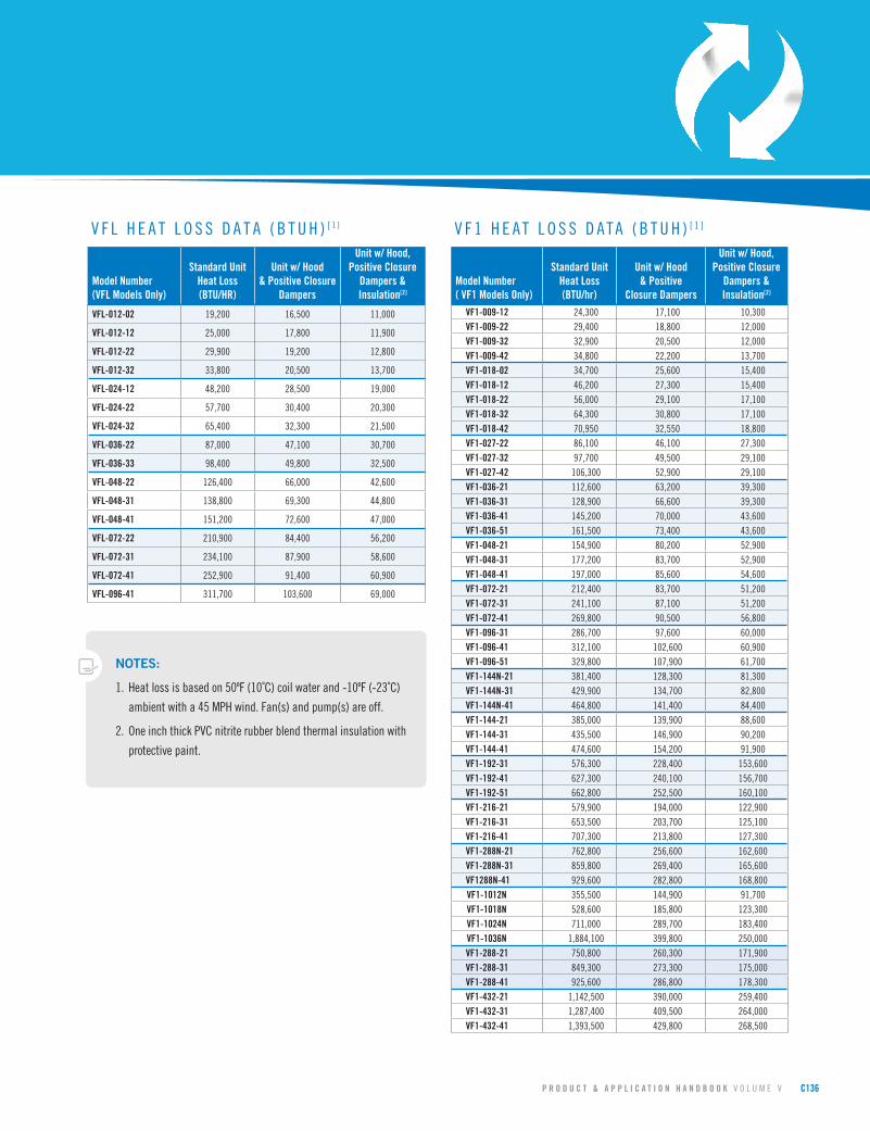
P R O D U C T & A P P L I C A T I O N H A N D B O O K V O L U M E V C136
V F L H E A T L O S S D A T A ( B T U H ) [ 1 ] V F 1 H E A T L O S S D A T A ( B T U H ) [ 1 ]
Model Number(VFL Models Only)
Standard UnitHeat Loss(BTU/HR)
Unit w/ Hood& Positive Closure
Dampers
Unit w/ Hood, Positive Closure
Dampers & Insulation[2]
VFL-012-02 19,200 16,500 11,000
VFL-012-12 25,000 17,800 11,900
VFL-012-22 29,900 19,200 12,800
VFL-012-32 33,800 20,500 13,700
VFL-024-12 48,200 28,500 19,000
VFL-024-22 57,700 30,400 20,300
VFL-024-32 65,400 32,300 21,500
VFL-036-22 87,000 47,100 30,700
VFL-036-33 98,400 49,800 32,500
VFL-048-22 126,400 66,000 42,600
VFL-048-31 138,800 69,300 44,800
VFL-048-41 151,200 72,600 47,000
VFL-072-22 210,900 84,400 56,200
VFL-072-31 234,100 87,900 58,600
VFL-072-41 252,900 91,400 60,900
VFL-096-41 311,700 103,600 69,000
Model Number( VF1 Models Only)
Standard UnitHeat Loss(BTU/hr)
Unit w/ Hood& Positive
Closure Dampers
Unit w/ Hood, Positive Closure
Dampers & Insulation[2]
VF1-009-12 24,300 17,100 10,300VF1-009-22 29,400 18,800 12,000VF1-009-32 32,900 20,500 12,000VF1-009-42 34,800 22,200 13,700VF1-018-02 34,700 25,600 15,400VF1-018-12 46,200 27,300 15,400VF1-018-22 56,000 29,100 17,100VF1-018-32 64,300 30,800 17,100VF1-018-42 70,950 32,550 18,800VF1-027-22 86,100 46,100 27,300VF1-027-32 97,700 49,500 29,100VF1-027-42 106,300 52,900 29,100VF1-036-21 112,600 63,200 39,300VF1-036-31 128,900 66,600 39,300VF1-036-41 145,200 70,000 43,600VF1-036-51 161,500 73,400 43,600VF1-048-21 154,900 80,200 52,900VF1-048-31 177,200 83,700 52,900VF1-048-41 197,000 85,600 54,600VF1-072-21 212,400 83,700 51,200VF1-072-31 241,100 87,100 51,200VF1-072-41 269,800 90,500 56,800VF1-096-31 286,700 97,600 60,000VF1-096-41 312,100 102,600 60,900VF1-096-51 329,800 107,900 61,700VF1-144N-21 381,400 128,300 81,300VF1-144N-31 429,900 134,700 82,800VF1-144N-41 464,800 141,400 84,400VF1-144-21 385,000 139,900 88,600VF1-144-31 435,500 146,900 90,200VF1-144-41 474,600 154,200 91,900VF1-192-31 576,300 228,400 153,600VF1-192-41 627,300 240,100 156,700VF1-192-51 662,800 252,500 160,100VF1-216-21 579,900 194,000 122,900VF1-216-31 653,500 203,700 125,100VF1-216-41 707,300 213,800 127,300VF1-288N-21 762,800 256,600 162,600VF1-288N-31 859,800 269,400 165,600VF1288N-41 929,600 282,800 168,800
VF1-1012N 355,500 144,900 91,700 VF1-1018N 528,600 185,800 123,300 VF1-1024N 711,000 289,700 183,400 VF1-1036N 1,884,100 399,800 250,000
VF1-288-21 750,800 260,300 171,900VF1-288-31 849,300 273,300 175,000VF1-288-41 925,600 286,800 178,300VF1-432-21 1,142,500 390,000 259,400VF1-432-31 1,287,400 409,500 264,000VF1-432-41 1,393,500 429,800 268,500
NOTES:
1. Heat loss is based on 50ºF (10˚C) coil water and -10ºF (-23˚C)
ambient with a 45 MPH wind. Fan(s) and pump(s) are off.
2. One inch thick PVC nitrite rubber blend thermal insulation with
protective paint.
Page 30
C137 Q U E S T I O N S ? C A L L 4 1 0 . 7 9 9 . 6 2 0 0 O R V I S I T W W W . B A L T I M O R E A I R C O I L . C O M
Series V Structural Support
TherecommendedsupportarrangementfortheSeriesVClosedCircuitCoolingTowerconsistsofparallelstructuralmembersrunningthefulllengthoftheunit,spacedasshowninthefollowingdrawing.Inadditiontoprovidingadequatesupport,themembersalsoservetoraisetheunitaboveanysolidfoundationtoensureaccesstothebottomofthetower.TosupportaSeriesVClosedCircuitCoolingTowerinanalternatesupportarrangement,consultyourlocalBACRepresentative.
VF1-009 thru -048, -072, -096, -144, & -1012NVFL Models
Model Number A BVFL-012 3’ -11” 4’ -6”VFL-024 3’ -11” 8’VFL-036 3’ -11” 11’VFL-048 3’ -11” 14’VFL-072 7’ -9” 11’VFL-096 7’ -9” 14’VF1-009 3’ -10” 2’ -6”VF1-018 3’ -10” 5’ -6”VF1-027 3’ -10” 8’ -6”VF1-036 3’ -10” 11’ -6”VF1-048 4’ -7” 11’ -6”VF1-072, 096 7’ -8” 10’ -8”VF1-144N 7’ -8” 16’ -8”VF1-192 7’ -8” 22’ -9”VF1-288N 7’ -8” 34’ -9”VF1-1012 9’ -8” 10’ -8”VF1-1018 9’ -8” 10’ -8”VF1-1024 9’ -8” 16’ -8”VF1-1036 9’ -8” 22’ -11”VF1-144 11’ -8” 33’ -7”VF1-216 11’ -8” 16’ -8”VF1-288 11’ -8” 22’ -9”VF1-432 11’ -8” 34’ -9”
NOTES:
1. Support members and anchor bolts shall be designed, furnished,
and installed by others.
2. Design of support members and anchor bolts shall be in accordance with
the strength and serviceability requirements of the applicable building
code and project specifications.
3. Support members shall be level at the top.
4. Refer to the certified unit support drawing for loading and additional
support requirements.
5. If vibration isolation (provided by others) is used, the isolators should be
located under a structural base that complies with one of the recommended
support arrangements. Contact your local BAC Representative for all other
isolator configurations.
VF1-288N, -432, & -1036NVF1-144N, -192, -216, -288, -1018N, & -1024