32
SERVICE MANUAL Rocket ® Digital Oocyte Aspiration Pump
SERVICE MANUAL
Rocket® Digital Oocyte Aspiration Pump

Rocket® Digital Oocyte Aspiration Pump – Service Manual
2 Copyright© 2013-19 Rocket Medical plc. . All rights reserved. ZDOCK258 Rev:7 25/02/19
1. CONTENTS SERVICE MANUAL .......................................................................................................................................................... 1 Rocket Digital Oocyte Aspiration Pump ............................................................................................................................ 1 1. CONTENTS................................................................................................................................................................... 2 2. GENERAL ASSEMBLY ................................................................................................................................................. 3
2.1. Rocket Digital Oocyte Aspiration Pump .......................................................................................................... 3
2.2. Rocket Digital Oocyte Aspiration Pump – Internal View ................................................................................. 4
3. GENERAL DESCRIPTION: .......................................................................................................................................... 5
3.1. INDICATIONS: ....................................................................................................................................................... 5
3.2. CONTRAINDICATIONS: ........................................................................................................................................ 5
3.3. CLASSIFICATION .................................................................................................................................................. 5
3.4. REFERENCES: ...................................................................................................................................................... 5
4. GENERAL INFORMATION ........................................................................................................................................... 6
4.1. COPYRIGHT .......................................................................................................................................................... 6
4.2. MODEL NUMBER: ................................................................................................................................................. 6
4.3. MANUAL REVISION: ............................................................................................................................................. 6
4.4. MANUFACTURER: ................................................................................................................................................ 7
4.5. SERVICE AGENTS: ............................................................................................................................................... 7
4.6. SUPPLY VOLTAGE SELECTION .......................................................................................................................... 8
4.7. ELECTROMAGNETIC COMPATIBILITY ............................................................................................................... 8
4.8. PACKAGING .......................................................................................................................................................... 8
4.9. POSITIONING and PLACEMENT of the DEVICE ................................................................................................. 8
4.9. SYMBOLS USED ON OOCYTE ASPIRATION PUMP. ......................................................................................... 9
4.10. SYMBOLS USED ON POWER SUPPLY UNIT. ................................................................................................ 10
4.11. SYMBOLS USED ON R57686 PATIENT CONNECTION SET. ........................................................................ 10
5. ANNUAL SERVICE ..................................................................................................................................................... 11
6.1 Replacing the inlet and exhaust filters ............................................................................................................... 11
6.2 Replacing the pump valve & diaphragm set ...................................................................................................... 13
6.3 Reassembling the chassis into the casing ......................................................................................................... 16
6. FINAL TESTING: ........................................................................................................................................................ 18 7. CLEANING THE PUMP CASING ............................................................................................................................... 19 8. YEAR OF MANUFACTURE: ....................................................................................................................................... 19 9. RETURNING THE PUMP FOR FACTORY REPAIR OR SERVICE: ......................................................................... 19 10. STORAGE & TRANSPORTATION: .......................................................................................................................... 20 11. OPERATING: ............................................................................................................................................................ 20 12. WARRANTY .............................................................................................................................................................. 21 13. DISPOSAL: ............................................................................................................................................................... 21 14. TECHNICAL SPECIFICATIONS ............................................................................................................................... 22
14.1. CLASSIFICATION .............................................................................................................................................. 22
14.2. SPECIFICATIONS .............................................................................................................................................. 22
15. DRAWINGS............................................................................................................................................................... 23
15.1. Set-up Flow Chart ............................................................................................................................................... 23
16. Circuit Diagram ......................................................................................................................................................... 26 17. Parts List – Main Assembly ....................................................................................................................................... 30 18. Parts List – PCB Assembly ....................................................................................................................................... 32

Rocket® Digital Oocyte Aspiration Pump – Service Manual
3 Copyright© 2013-19 Rocket Medical plc. . All rights reserved. ZDOCK258 Rev:7 25/02/19
2. GENERAL ASSEMBLY
2.1. Rocket Digital Oocyte Aspiration Pump
Rocket Digital Oocyte Aspiration Pump
1. Touch sensitive Suction Control Dial – clockwise to increase, anticlockwise to decrease the set value
2. Suction Display in mmHg-1
3. Patient connection port – only for use with R57686 Rocket Oocyte Aspiration Pump Patient Connection Sets
4. Power On Indicator LED (Green, 12VDC)
5. Footswitch connection ports
6. User Set Suction Indicator LED (Blue,50-300mmHg-1)
7. Pre-set (Max) Suction Indicator LED (Orange, 500mmHg-1)
8. Service Indicator LED (Yellow)
9. O/I 12V Power On/Off switch
10. Dual footswitch – air controlled
Not shown:
11. Power Supply Unit (PSU) Model: MPU30
12. Power cords, IEC UK & EC types.

Rocket® Digital Oocyte Aspiration Pump – Service Manual
4 Copyright© 2013-19 Rocket Medical plc. . All rights reserved. ZDOCK258 Rev:7 25/02/19
2.2. Rocket Digital Oocyte Aspiration Pump – Internal View
1. O/I Mains Power On/Off
2. Vacuum display 0-500mmHg-1 – normal range 50-300mmHg-1
3. Motor 12V
4. Pump head including valve housing
5. Vacuum outlet port
6. Vacuum inlet filter
7. Vacuum control solenoid
8. Internal silencer with filter chamber (A)
9. Internal silencer with filter chamber (B)
10. Internal exhaust vent and filter
11. Control PCB with ribbon cable to vacuum control touch wheel

Rocket® Digital Oocyte Aspiration Pump – Service Manual
5 Copyright© 2013-19 Rocket Medical plc. . All rights reserved. ZDOCK258 Rev:7 25/02/19
3. GENERAL DESCRIPTION: The Rocket Oocyte Aspiration Pump has been developed to provide smooth, low volume/high suction (vacuum) at a pre-determined negative pressure. Suction is activated by a foot operated toggle air switch controlled by the surgeon performing the oocyte collection.
The range of suction is variable from 50-300mmHg-1 and at a pre-set 500mmHg-1 in ‘Max’ suction mode.
The Rocket Oocyte Aspiration Pump requires a disposable filter set for attachment of the pump to the oocyte collection needle. The filter set is supplied separately, sterile and for single patient use.
You will also require:
A suitable oocyte aspiration needle such as Rocket SX Single Lumen Oocyte Aspiration Set (R57602-00-90)
Suitable collection tubes for use with oocyte needle sets such as B.D. Falcon test tube No. 2001F, 17 x 100mm.
Flushing media
3.1. INDICATIONS:
For the generation of high vacuum/low volume suction between 50-500 mmHg-1 to permit the aspiration of follicular fluid, oocytes and ovarian fluid as part of the treatment of infertility relating to IVF and other gynaecological procedures.
3.2. CONTRAINDICATIONS:
Not intended for use where ovarian aspiration or the aspiration of ovarian fluid is contraindicated. For short term operation only. The device is NOT intended for continuous drainage.
3.3.CLASSIFICATION
IEC 60601-1: 2005
Type of protection against electric shock: Class II
Degree of protection against electric shock: Type B
Vacuum type: high vacuum/low volume
Suitable for continuous operation.
Not suitable for use in the presence of flammable gases.
Not suitable for use in conditions which expose the device to the ingress of fluids.
Not suitable for sterilisation
3.4. REFERENCES:
Craft I, McLeod F. Edmonds K, ‘Human embryo transfer technique’. Lancet 1961 ii 1104-5
Craft I, Diahanbakch O. McLeod F et al ‘Human pregnancy following oocyte and sperm transfer to the uterus.’ Lancet 1992 i 1031-3
Craft I, (1984) ‘Clinical Methodology’ British Journal of Hospital Medicine 90-102
Reeves G, Scott R T, et al (1989) Journal of Assisted Reproduction and Genetics Volume 6, Number 6 / December, 1989

Rocket® Digital Oocyte Aspiration Pump – Service Manual
6 Copyright© 2013-19 Rocket Medical plc. . All rights reserved. ZDOCK258 Rev:7 25/02/19
WARNING: READ THIS MANUAL CAREFULLY: Please familiarise yourself with the contents of this manual before attempting to use the device.
Failure to observe these instructions may result in damage to the pump or cause injury to the patient or user.
This device should only be used by suitably qualified personnel.
WARNING: ELECTRIC SHOCK HAZARD. The equipment is to be used only with electrical systems complying with all IEC, CEC and NEC requirements.
4. GENERAL INFORMATION
4.1. COPYRIGHT This manual contains information that is subject to copyright. All rights reserved. This manual should not be photocopied, duplicated or distributed completely or in part without the written approval of Rocket Medical plc.
4.2.MODEL NUMBER:
Rocket Digital Suction Pump Complete R29700
Power supply: MPU30
4.3. MANUAL REVISION: Revision 1 First Publication 05/11/13 Revision 2 Update of LRQA CE mark 27/08/14 Revision 3 Update to EN 60601-1:2006 10/07/16 Revision 4 Correction PSU current and voltage 10/08/16 Revision 5 Correction of operating temperature 12/08/16 Revision 6 Update cover image, add flowcharts 21/01/19 Revision 7 Updater service agent, warranty 25/02/19
Rocket® Digital Oocyte Aspiration Pump – Service Manual
7 Copyright© 2013-19 Rocket Medical plc. . All rights reserved. ZDOCK258 Rev:7 25/02/19
CAUTION: Any adjustment, modification or repairs to the equipment should be carried out by authorised service agents.
Disposal of this device must be undertaken with regard to the WEEE directive (2002/96/EC).
4.4. MANUFACTURER:
Rocket Medical plc Sedling Road WASHINGTON Tyne & Wear NE38 9BZ UK.
4.5. SERVICE AGENTS:
Rocket Digital Pumps require servicing when indicated by the Service Indicator.
It is recommended they are serviced and calibrated at an approved Rocket Medical plc service facility.
Failure to service the pump at the indicated intervals and with an authorised service agent may invalidate the Warranty. UK & European Service Agents: Hunter Scientific Limited Unit 1, Priors Hall Widdington Saffron Walden Essex CB11 3SB Tel: +44 (0)1799 541 688 Fax +44 (0)1799 541 703 E: [email protected] W: www.hunterscientfic.com
UK Customer Services:
Rocket Medical plc. Sedling Road. WASHINGTON. NE38 9BZ. ENGLAND Tel: +44 (0) 191 419 6988. Fax: +44 (0) 191 419 6989 Email: [email protected]
US Office:
Email: [email protected] Rocket Medical 50 Corporate Park Drive. Suite 890. PEMBROKE. MA. 02359. USA Tel: +1 781 749 6223
Rocket® Digital Oocyte Aspiration Pump – Service Manual
8 Copyright© 2013-19 Rocket Medical plc. . All rights reserved. ZDOCK258 Rev:7 25/02/19
WARNING: ELECTRIC SHOCK HAZARD. The equipment is to be used only with electrical systems complying with all IEC, CEC and NEC requirements.
WARNING: ELECTRIC SHOCK HAZARD. Do not immerse the device.
WARNING: Device can cause explosion in the presence of flammable gases.
4.6. SUPPLY VOLTAGE SELECTION
The device is only for use with power supply Model Number: MPU30 with 12VDC output. Attachment of any other power supply may severely damage the device.
CAUTION: Disconnection from the mains supply can only be achieved with the removal of the mains power lead from the wall socket.
The device operates at a voltage 100V to 240 VAC @ 50 / 60Hz. 0.15A
4.7.ELECTROMAGNETIC COMPATIBILITY
Rocket Craft Suction Pumps comply with the electromagnetic compatibility (EMC) limits for medical devices as specified by EN 60601-1-2:2015. These limits are designed to provide a reasonable degree of protection against harmful interference found in typical medical installations.
Medical electrical equipment requires special precautions regarding EMC and the device must be installed, positioned and operated according to the instructions contained in this manual to ensure continued electromagnetic compatibility.
The device must be operated according to the instructions contained in this manual to ensure continued electromagnetic compatibility.
4.8.PACKAGING The packaging has been designed to allow secure transportation of the pump and its accessories.
After unpacking, re-assemble and retain the packaging for transport for servicing when required.
4.9. POSITIONING and PLACEMENT of the DEVICE Rocket Digital Oocyte Aspiration Pumps must be placed on a secure, level surface, away from sources of heat, water splashes, mists or cooling vents.
Do not expose to direct sunlight.
Do not expose to flammable gases.
Operating temperature Range: +5°C and +40°C
Rocket® Digital Oocyte Aspiration Pump – Service Manual
9 Copyright© 2013-19 Rocket Medical plc. . All rights reserved. ZDOCK258 Rev:7 25/02/19
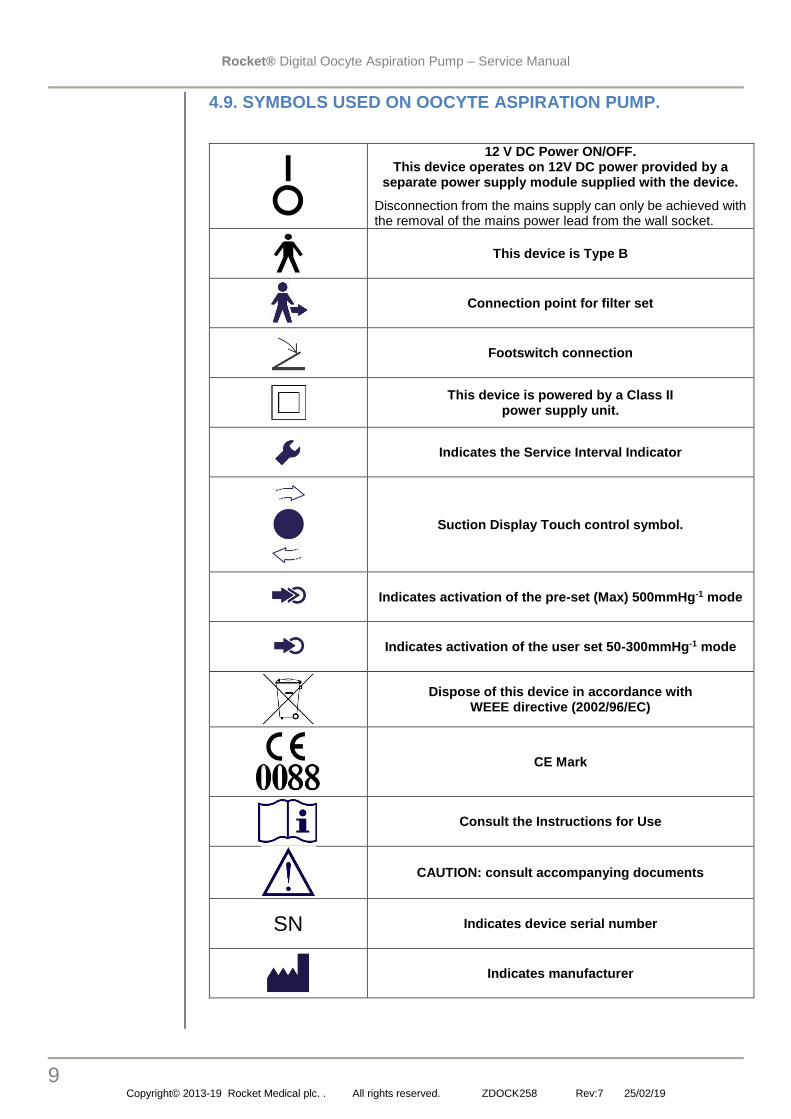
4.9. SYMBOLS USED ON OOCYTE ASPIRATION PUMP.
12 V DC Power ON/OFF. This device operates on 12V DC power provided by a
separate power supply module supplied with the device.
Disconnection from the mains supply can only be achieved with the removal of the mains power lead from the wall socket.
This device is Type B
Connection point for filter set
Footswitch connection
This device is powered by a Class II power supply unit.
Indicates the Service Interval Indicator
Suction Display Touch control symbol.
Indicates activation of the pre-set (Max) 500mmHg-1 mode
Indicates activation of the user set 50-300mmHg-1 mode
Dispose of this device in accordance with WEEE directive (2002/96/EC)
CE Mark
Consult the Instructions for Use
CAUTION: consult accompanying documents
SN Indicates device serial number
Indicates manufacturer

Rocket® Digital Oocyte Aspiration Pump – Service Manual
10 Copyright© 2013-19 Rocket Medical plc. . All rights reserved. ZDOCK258 Rev:7 25/02/19
4.10. SYMBOLS USED ON POWER SUPPLY UNIT.
Read the manual before connection and use
WARNING: Risk of electric shock. The PSU should not be opened
Device is only for use indoors
Class II Power Supply Unit
12V DC connection polarity
Dispose of this device in accordance with WEEE directive (2002/96/EC)
PSU conforms to EN60601-1 & IEC60601-1
CE Mark
4.11. SYMBOLS USED ON R57686 PATIENT CONNECTION SET.
Read the Instruction for Use before connection and use
Device is for Single Use Only
Batch number for sterile device
Device is sterilised by Ethylene Oxide
The device is not manufactured with natural latex
CE Mark

Rocket® Digital Oocyte Aspiration Pump – Service Manual
11 Copyright© 2013-19 Rocket Medical plc. . All rights reserved. ZDOCK258 Rev:7 25/02/19
WARNING: Observe precautions for handling electrostatic discharge sensitive devices
5. ANNUAL SERVICE
6.1 Replacing the inlet and exhaust filters
1. Lay the pump on a clean surface, protecting the casing from scratches.
2. Remove 3 screws from the rear casing and retain
3. Turn the pump over and remove 3 screws from the front lower casing and retain
4. Remove white silicone retaining ‘O’ ring from vacuum inlet port
5. CAUTION: Avoid the use of sharp tools as these may damage the O’ ring.

Rocket® Digital Oocyte Aspiration Pump – Service Manual
12 Copyright© 2013-19 Rocket Medical plc. . All rights reserved. ZDOCK258 Rev:7 25/02/19
6. Detach ribbon cable from the front panel vacuum controller PCB by lifting the tab
7. Carefully detach the ribbon from the front cover and store securely.
8. Detach patient outlet filter from tube
9. Unclip filter from spring clip, discard and replace filter.

Rocket® Digital Oocyte Aspiration Pump – Service Manual
13 Copyright© 2013-19 Rocket Medical plc. . All rights reserved. ZDOCK258 Rev:7 25/02/19
IMPORTANT
6.2 Replacing the pump valve & diaphragm set
9. Unscrew two securing nuts and lift out chassis to gain access to pump head.
10. Angle chassis to support on casing
11. Unscrew 4 screws form the pump head in a crosswise manner to prevent distortion of the pump head
12. Discard and replace the pump head/valve module
13. Discard and replace the pump head/valve module
Rocket® Digital Oocyte Aspiration Pump – Service Manual
14 Copyright© 2013-19 Rocket Medical plc. . All rights reserved. ZDOCK258 Rev:7 25/02/19
IMPORTANT
IMPORTANT
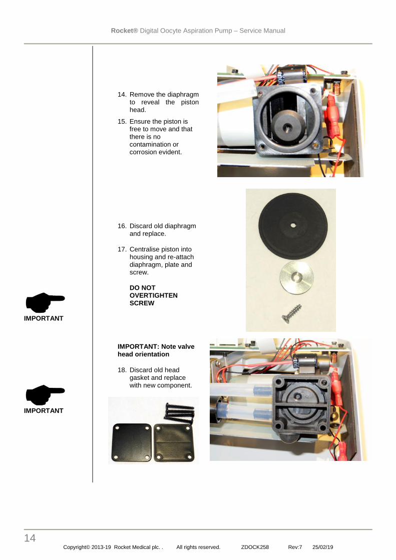
14. Remove the diaphragm to reveal the piston head.
15. Ensure the piston is free to move and that there is no contamination or corrosion evident.
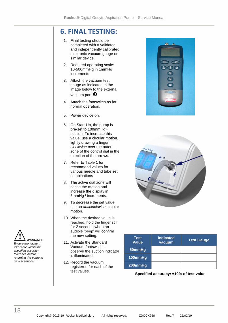
16. Discard old diaphragm and replace.
17. Centralise piston into housing and re-attach diaphragm, plate and screw.
DO NOT OVERTIGHTEN SCREW
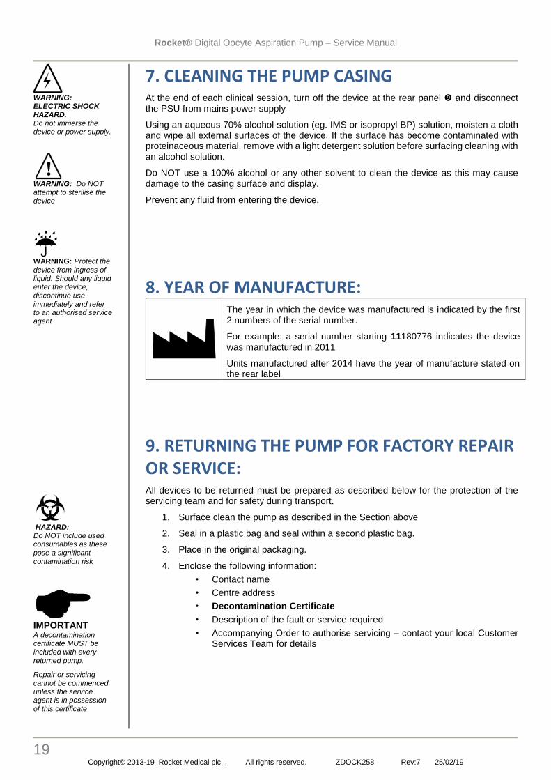
IMPORTANT: Note valve head orientation
18. Discard old head gasket and replace with new component.

Rocket® Digital Oocyte Aspiration Pump – Service Manual
15 Copyright© 2013-19 Rocket Medical plc. . All rights reserved. ZDOCK258 Rev:7 25/02/19
IMPORTANT
19. Re-attach inlet vacuum tubing to TOP port
20. Re-attach exhaust filter to BOTTOM port.
21. Relocate exhaust filter in bottom of case
22. Tighten screws in a crosswise fashion to avoid distorting the pump head.
DO NOT OVER TIGHTEN
23. Return chassis into casing
24. Re-tighten two securing nuts.

Rocket® Digital Oocyte Aspiration Pump – Service Manual
16 Copyright© 2013-19 Rocket Medical plc. . All rights reserved. ZDOCK258 Rev:7 25/02/19
VERY IMPORTANT
6.3 Reassembling the chassis into the casing
25. Pass patient outlet filter underneath tubing and re- attach filter to patient connection port tube.
26. Re-clip filter into spring clip
27. Ensure tubing is not trapped by spring clip and correctly routed to avoid occlusion
28. Re-attach ribbon cable from PCB to the front panel vacuum controller PCB by lifting the tab
29. Carefully inserting the ribbon and closing the tab securely.

Rocket® Digital Oocyte Aspiration Pump – Service Manual
17 Copyright© 2013-19 Rocket Medical plc. . All rights reserved. ZDOCK258 Rev:7 25/02/19
IMPORTANT DO NOT OVER TIGHTEN THE SCREWS
CAUTION: Avoid the use of sharp tools as these may damage the O’ ring.
30. Lay the pump on a clean surface, protecting the casing from scratches.
31. After re-assembling the upper casing to the lower frame, re-install 3 screws to the rear casing
32. Turn the pump over and re-install 3 screws to the front lower casing.
33. Re-install the white silicone retaining ‘O’ ring to the vacuum inlet port.
Rocket® Digital Oocyte Aspiration Pump – Service Manual
18 Copyright© 2013-19 Rocket Medical plc. . All rights reserved. ZDOCK258 Rev:7 25/02/19
WARNING: Ensure the vacuum levels are within the specified accuracy tolerance before returning the pump to clinical service.
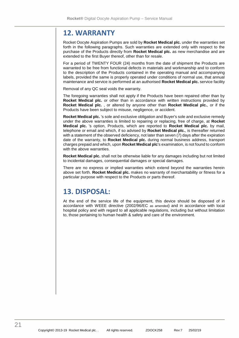
6. FINAL TESTING: 1. Final testing should be
completed with a validated and independently calibrated electronic vacuum gauge or similar device.
2. Required operating scale: 10-500mmHg in 1mmHg increments
3. Attach the vacuum test gauge as indicated in the image below to the external
vacuum port
4. Attach the footswitch as for normal operation.
5. Power device on.
6. On Start-Up, the pump is pre-set to 100mmHg-1 suction. To increase this value, use a circular motion, lightly drawing a finger clockwise over the outer zone of the control dial in the direction of the arrows.
7. Refer to Table 1 for recommend values for various needle and tube set combinations
8. The active dial zone will sense the motion and increase the display in 5mmHg-1 increments.
9. To decrease the set value, use an anticlockwise circular motion.
10. When the desired value is reached, hold the finger still for 2 seconds when an audible ‘beep’ will confirm the new setting.
11. Activate the Standard Vacuum footswitch – observe the suction indicator is illuminated.
12. Record the vacuum registered for each of the test values.
Test Value
Indicated vacuum
Test Gauge
50mmHg
100mmHg
200mmHg
Specified accuracy: ±10% of test value
Rocket® Digital Oocyte Aspiration Pump – Service Manual
19 Copyright© 2013-19 Rocket Medical plc. . All rights reserved. ZDOCK258 Rev:7 25/02/19
WARNING: ELECTRIC SHOCK HAZARD. Do not immerse the device or power supply.
WARNING: Do NOT attempt to sterilise the device
WARNING: Protect the device from ingress of liquid. Should any liquid enter the device, discontinue use immediately and refer to an authorised service agent
HAZARD: Do NOT include used consumables as these pose a significant contamination risk
IMPORTANT A decontamination certificate MUST be included with every returned pump.
Repair or servicing cannot be commenced unless the service agent is in possession of this certificate
7. CLEANING THE PUMP CASING At the end of each clinical session, turn off the device at the rear panel and disconnect the PSU from mains power supply
Using an aqueous 70% alcohol solution (eg. IMS or isopropyl BP) solution, moisten a cloth and wipe all external surfaces of the device. If the surface has become contaminated with proteinaceous material, remove with a light detergent solution before surfacing cleaning with an alcohol solution.
Do NOT use a 100% alcohol or any other solvent to clean the device as this may cause damage to the casing surface and display.
Prevent any fluid from entering the device.
8. YEAR OF MANUFACTURE:
The year in which the device was manufactured is indicated by the first 2 numbers of the serial number.
For example: a serial number starting 11180776 indicates the device was manufactured in 2011
Units manufactured after 2014 have the year of manufacture stated on the rear label
9. RETURNING THE PUMP FOR FACTORY REPAIR OR SERVICE: All devices to be returned must be prepared as described below for the protection of the servicing team and for safety during transport.
1. Surface clean the pump as described in the Section above
2. Seal in a plastic bag and seal within a second plastic bag.
3. Place in the original packaging.
4. Enclose the following information:
• Contact name
• Centre address
• Decontamination Certificate
• Description of the fault or service required
• Accompanying Order to authorise servicing – contact your local Customer Services Team for details

Rocket® Digital Oocyte Aspiration Pump – Service Manual
20 Copyright© 2013-19 Rocket Medical plc. . All rights reserved. ZDOCK258 Rev:7 25/02/19
10. STORAGE & TRANSPORTATION:
The device must be transported/stored at temperatures between -10°C to + 50°C
The device must be transported/stored at relative humidity levels between 20% to 95%
The device must be stored in a clean, dry condition, ideally in its original packaging which should be retained to return the unit for servicing
Protect the device from ingress of liquid. Should any liquid enter the device, discontinue use immediately and refer to an authorised service agent
11. OPERATING:
The device’s operating temperature range: +5°C to + 40°C
The device must be operated at relative humidity levels between 15% to 93%
The device must be operated at ambient pressure levels between 70kPa to 106kPa.
The device is FRAGILE and must be transported in its original packaging to ensure protection.
If the original packaging is not available please contact your local Customer Services Agent who will provide replacement packaging.
Dimensions:
W - 248mm H - 86mm D - 194mm
Weight:
Unit – 2.56Kg Footswitch – 0.51Kg
Protect the device from ingress of liquid. Should any liquid enter the device, discontinue use immediately and refer to an authorised service agent
Altitude This device is intended for use below 2000 meters.
Rocket® Digital Oocyte Aspiration Pump – Service Manual
21 Copyright© 2013-19 Rocket Medical plc. . All rights reserved. ZDOCK258 Rev:7 25/02/19
12. WARRANTY Rocket Oocyte Aspiration Pumps are sold by Rocket Medical plc. under the warranties set forth in the following paragraphs. Such warranties are extended only with respect to the purchase of the Products directly from Rocket Medical plc. as new merchandise and are extended to the first Buyer thereof, other than for resale.
For a period of TWENTY FOUR (24) months from the date of shipment the Products are warranted to be free from functional defects in materials and workmanship and to conform to the description of the Products contained in the operating manual and accompanying labels, provided the same is properly operated under conditions of normal use, that annual maintenance and service is performed at an authorised Rocket Medical plc. service facility
Removal of any QC seal voids the warranty.
The foregoing warranties shall not apply if the Products have been repaired other than by Rocket Medical plc. or other than in accordance with written instructions provided by Rocket Medical plc. , or altered by anyone other than Rocket Medical plc., or if the Products have been subject to misuse, negligence, or accident.
Rocket Medical plc. 's sole and exclusive obligation and Buyer's sole and exclusive remedy under the above warranties is limited to repairing or replacing, free of charge, at Rocket Medical plc. 's option, Products, which are reported to Rocket Medical plc. by mail, telephone or email and which, if so advised by Rocket Medical plc., is thereafter returned with a statement of the observed deficiency, not later than seven (7) days after the expiration date of the warranty, to Rocket Medical plc. during normal business address, transport charges prepaid and which, upon Rocket Medical plc's examination, is not found to conform with the above warranties.
Rocket Medical plc. shall not be otherwise liable for any damages including but not limited to incidental damages, consequential damages or special damages.
There are no express or implied warranties which extend beyond the warranties herein above set forth. Rocket Medical plc. makes no warranty of merchantability or fitness for a particular purpose with respect to the Products or parts thereof.
13. DISPOSAL: At the end of the service life of the equipment, this device should be disposed of in accordance with WEEE directive (2002/96/EC as amended) and in accordance with local hospital policy and with regard to all applicable regulations, including but without limitation to, those pertaining to human health & safety and care of the environment.

Rocket® Digital Oocyte Aspiration Pump – Service Manual
22 Copyright© 2013-19 Rocket Medical plc. . All rights reserved. ZDOCK258 Rev:7 25/02/19
14. TECHNICAL SPECIFICATIONS
14.1. CLASSIFICATION
IEC 60601-1
Type of protection against electric shock: Class II
Degree of protection against electric shock: Type B
Vacuum type: high vacuum/low volume
Suitable for continuous operation.
Not suitable for use in the presence of flammable gases.
Not suitable for use in conditions which expose the device to the ingress of water.
Not suitable for sterilisation
14.2. SPECIFICATIONS
Power Input to Pump: 12VDC
Universal Power Supply: 100 - 240VAC
Frequency: 50/60 Hz
Maximum current: 2.5A @ 12V
Environmental conditions: +5°C to +40°C
Service interval: 1000hrs of pump operation.
Dimensions:
W - 248mm
H - 86mm
D - 194mm
Weight:
Unit - 2.56Kg
Foot Switch 0.51Kg
Suction Ranges:
User Set: -50mmHg to -300mmHg-1 in 5mmHg increments
Pre-set: -500mmHg - nominal
Suction Range Accuracy: ±10% at operating range: 100-500mmHg-1

Rocket® Digital Oocyte Aspiration Pump – Service Manual
23 Copyright© 2013-19 Rocket Medical plc. . All rights reserved. ZDOCK258 Rev:7 25/02/19
15. DRAWINGS
15.1. Set-up Flow Chart
Rocket® Digital Oocyte Aspiration Pump – Service Manual
24 Copyright© 2013-19 Rocket Medical plc. . All rights reserved. ZDOCK258 Rev:7 25/02/19
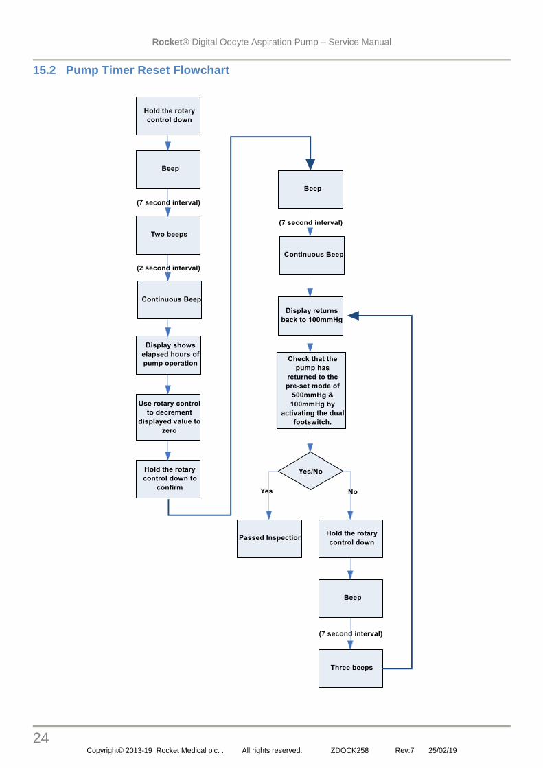
15.2 Pump Timer Reset Flowchart

Rocket® Digital Oocyte Aspiration Pump – Service Manual
25 Copyright© 2013-19 Rocket Medical plc. . All rights reserved. ZDOCK258 Rev:7 25/02/19
15.3 Service Mode Reset Flowchart

Rocket® Digital Oocyte Aspiration Pump – Service Manual
26 Copyright© 2013-19 Rocket Medical plc. . All rights reserved. ZDOCK258 Rev:7 25/02/19
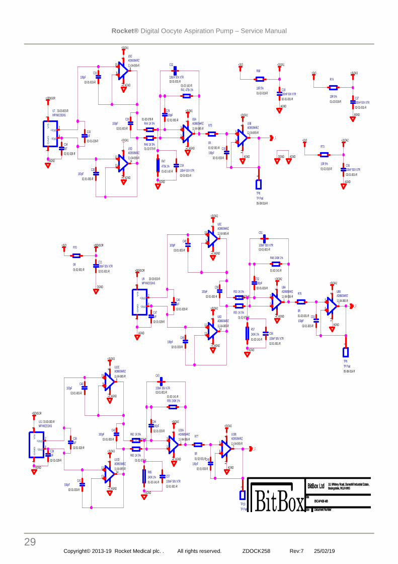
16. Circuit Diagram
5
5
4
4
3
3
2
2
1
1
D D
C C
B B
A A
DRDYSPCKMOSI
NPCS0
CHANGE
MISO
PWR_LEDBLUE_LED
ORNG_LED
DBG_TXD
DBG_TXDDBG_RXD
DBG_RXD
DGND
DGND
+3V3
+Vcore+3V3
DGND
DGND
DGND
+3V3
DGND
+3V3
DGND
DGND
+3V3
DGND
DGND
+3V3
+3V3
DGND
+12V
+12V
+3V3
DGND
+3V3
DGND DGND
DGND
+3V3 +Vcore
SEG_ASEG_BSEG_CSEG_DSEG_ESEG_FSEG_G
DIG_1DIG_2DIG_3
P_1P_2P_3
MOTORVALVE1VALVE2
Title
Size Document Number Rev
Date: Sheet of
10, Whitney Road, Daneshill Industrial Estate,Basingstoke, RG24 8NSBitBox Ltd
09CAP436-MB D
09CAP436-MB
A3
2 6Friday, October 26, 2012
Title
Size Document Number Rev
Date: Sheet of
10, Whitney Road, Daneshill Industrial Estate,Basingstoke, RG24 8NSBitBox Ltd
09CAP436-MB D
09CAP436-MB
A3
2 6Friday, October 26, 2012
Title
Size Document Number Rev
Date: Sheet of
10, Whitney Road, Daneshill Industrial Estate,Basingstoke, RG24 8NSBitBox Ltd
09CAP436-MB D
09CAP436-MB
A3
2 6Friday, October 26, 2012
U1A74HC0408-03-006-R
1 2
14
7
+
SU1
ABI-001-RC
27-01-006-R
P
N
R12 100R 5%01-02-101-R
TP1
TP Pad
05-08-016-R
1
C20100nF 50V X7R
02-01-001-RC2
2.2
uF
1
6V
X
7R
02
-0
2-0
11
-R
C1
10
0n
F 5
0V
X
7R
02
-0
1-0
01
-R
R4 100R 5%01-02-101-R
TP4
TP Pad
05-08-016-R
1
C710nF 50V X7R
02-01-007-R
U1B74HC0408-03-006-R
3 4
14
7
R5
10
K 5
%
01
-0
2-0
05
-R
LED1
04-01-014-R
0805 LED orange
AC
R13820R
01-02-027-R
C54100nF 50V X7R
02-01-001-R
C56100nF 50V X7R
02-01-001-RC3
2.2
uF
1
6V
X
7R
02
-0
2-0
11
-R
J1
14W 1mm horiz BC FFC
05-28-025-R
123456789
1011121314
Q6
2N7002
07-02-006-R
D
G
S
C5
10
0n
F 5
0V
X
7R
02
-0
1-0
01
-R
R6
10
K 5
%
01
-0
2-0
05
-R
SW1
14-01-013-RB3F-1000
2
4
1
3
R2
10
0R
5
%
01
-0
2-1
01
-R
C61nF X7R02-01-004-R
R9
10
K 5
%
01
-0
2-0
05
-R
R3
100R 5%01-02-101-R
Q4
2N7002
07-02-006-R
D
G
S
R10 10K 5%01-02-005-R
R8 100R 5%01-02-101-R
U2AT91SAM7S64B-AU
09-04-010-R
ADVref1
GN
D1
2
AD43
AD54
AD65
AD76
VD
Din
7
VD
Do
ut
8
PA17/AD0/TD/PCK19
PA18/AD1/RD/PCK210
PA21/RXD1/PCK111
VD
Dcore1
12
PA19/AD2/RK/FIQ13
PA22/TXD1/NPCS314
PA23/SCK1/PWM015
PA20/AD3/RF/IRQ016
GN
D2
17
VD
Dio1
18
PA16/TK/TIOB119PA15/TF/TIOA120PA14/SPCK/PWM321PA13/MOSI/PWM222
PA24/RTS1/PWM123
VD
Dcore2
24
PA25/CTS1/PWM225
PA26/DCD1/TIOA226
PA12/MISO/PWM127PA11/NPCS0/PWM028
PA10/DTXD/NPCS229 PA9/DRXD/NPCS130
PA8/CTS0/ADTRG31PA7/RTS0/PWM332
TDI33
PA6/TXD0/PCK034PA5/RXD0/NPCS335PA4/TWCK/TCLK036
PA27/DTR1/TIOB237
PA28/DSR1/TCLK138NRST
39
TST40
PA29/RI1/TCLK241
PA30/IRQ1/NPCS242
PA3/TWD/NPCS343PA2/PWM2/SCK044
VD
Dio2
45
GN
D3
46
PA1/PWM1/TIOB047PA0/PWM0/TIOA048
TDO49
JTAGSEL50
TMS51
PA31/NPCS1/PCK252
TCK53
VD
Dcore3
54
ERASE55 DDM
56
DDP57
VD
Dio3
58
VD
Dflash
59
GN
D4
60
XOUT61
XIN62
PLLRC63
VD
Dp
ll
64
J3
01-02-044-R
0R Option 1-2
123
R11 10K 5%
01-02-005-R
C55100nF 50V X7R
02-01-001-R
C19100nF 50V X7R
02-01-001-R
TP2
TP Pad
05-08-016-R
1
R7
10
K 5
%
01
-0
2-0
05
-R
J2
JTAG+SER 1mm
05-08-015-R
JTAG-TCK1
GND12
JTAG-TDO3
JTAG-VIO4
JTAG-TMS5
SER-TXD6
SER-RXD7
JTAG-TRST8
JTAG-TDI9
GND210
Q5 20MHz13-02-004-R
C4
1n
F X
7R
02
-0
1-0
04
-R
R1
10
K 5
%
01
-0
2-0
05
-R
TP3
TP Pad
05-08-016-R
1

Rocket® Digital Oocyte Aspiration Pump – Service Manual
27 Copyright© 2013-19 Rocket Medical plc. . All rights reserved. ZDOCK258 Rev:7 25/02/19
55
44
33
22
11
DD
CC
BB
AA
Forward voltage
6.6 - 7.6 Volts
DG
ND
DG
ND
DG
ND
DG
ND
+12V+12V
+12V
+12V
+3V3DG
ND
+3V3DG
ND
+3V3DG
ND
+3V3DG
ND
SEG_A
SEG_B
SEG_C
SEG_D
SEG_E
SEG_F
SEG_G
DIG
_1D
IG_3
DIG
_2
Title
SizeD
ocument N
umber
Rev
Date:
Sheetof
10, Whitney R
oad, Daneshill Industrial Estate,
Basingstoke, RG
24 8NS
BitBox Ltd
09CAP436-M
BD
09CAP436-M
B
A3
36
Friday, October 26, 2012
Title
SizeD
ocument N
umber
Rev
Date:
Sheetof
10, Whitney R
oad, Daneshill Industrial Estate,
Basingstoke, RG
24 8NS
BitBox Ltd
09CAP436-M
BD
09CAP436-M
B
A3
36
Friday, October 26, 2012
Title
SizeD
ocument N
umber
Rev
Date:
Sheetof
10, Whitney R
oad, Daneshill Industrial Estate,
Basingstoke, RG
24 8NS
BitBox Ltd
09CAP436-M
BD
09CAP436-M
B
A3
36
Friday, October 26, 2012
R32 470R 5% 01-02-017-R
R28 470R 5% 01-02-017-R
R24 470R 5% 01-02-017-R
ab
cd
ef
gDP
abc
de f
g
DP
LED4
7 Seg 25mm
Blue CA
04-07-006-R
7
83
10
9
13
1
6
2
11
14
Q3A
SI4599DY
07-02-047-R
7
2
18
R20 470R 5% 01-02-017-R
R35 470R 5% 01-02-017-R
R17 470R 5% 01-02-017-R
R33 470R 5% 01-02-017-R
R29 470R 5% 01-02-017-R
TP7
TP Pad
05-08-016-R
1
R25 470R 5% 01-02-017-R
Q3B
SI4599DY
07-02-047-R
3
4
5 6
R36 470R 5% 01-02-017-R
TP6
TP Pad
05-08-016-R
1
R21 470R 5% 01-02-017-R
U1C
74HC
0408-03-006-R
56
147
Q1A
SI4599DY
07-02-047-R
7
2
18
U1F
74HC
0408-03-006-R
1312
147
TP5
TP Pad
05-08-016-R
1
ab
cd
ef
gDP
abc
de f
g
DP
LED2
7 Seg 25mm
Blue CA
04-07-006-R
7
83
10
9
13
1
6
2
11
14
R19 470R 5% 01-02-017-R
U1E
74HC
0408-03-006-R
1110
147
Q2A
SI4599DY
07-02-047-R
7
2
18
R30 470R 5% 01-02-017-R
U1D
74HC
0408-03-006-R
98
147
R26 470R 5% 01-02-017-R
R16
10K 5%01-02-005-R
R22 470R 5% 01-02-017-R
R37 470R 5% 01-02-017-R
Q1B
SI4599DY
07-02-047-R
3
4
5 6
Q2B
SI4599DY
07-02-047-R
3
4
5 6
ab
cd
ef
gDP
abc
de f
g
DP
LED3
7 Seg 25mm
Blue CA
04-07-006-R
7
83
10
9
13
1
6
2
11
14
R31 470R 5% 01-02-017-R
R18 470R 5% 01-02-017-R
R27 470R 5% 01-02-017-R
R23 470R 5% 01-02-017-R
R14
10K 5%01-02-005-R
R34 470R 5% 01-02-017-R
U3
07-01-002-R
ULN
2003 GN
D8
IN 1
1O
UT1
16
IN 2
2O
UT2
15
IN 3
3O
UT3
14
IN 4
4O
UT4
13
IN 5
5
IN 6
6
IN 7
7
OU
T512
OU
T611
OU
T710
CO
M9
R15
10K 5%01-02-005-R

Rocket® Digital Oocyte Aspiration Pump – Service Manual
28 Copyright© 2013-19 Rocket Medical plc. . All rights reserved. ZDOCK258 Rev:7 25/02/19
55
44
33
22
11
DD
CC
BB
AA
DG
ND
+12V
DG
ND
+12V
DG
ND
+12V
+3V3D
GN
D
+3V3D
GN
D
+3V3D
GN
D
DG
ND
+3V3D
GN
D
+3V3D
GN
D
+3V3D
GN
D
MO
TOR
VA
LVE
1
VA
LVE
2
Title
Size
Docum
ent Num
berR
ev
Date:
Sheet
of
10, Whitney R
oad, Daneshill Industrial E
state,B
asingstoke, RG
24 8NS
BitB
ox Ltd
09CA
P436-M
BD
09CA
P436-M
B
A4
46
Friday, October 26, 2012
Title
Size
Docum
ent Num
berR
ev
Date:
Sheet
of
10, Whitney R
oad, Daneshill Industrial E
state,B
asingstoke, RG
24 8NS
BitB
ox Ltd
09CA
P436-M
BD
09CA
P436-M
B
A4
46
Friday, October 26, 2012
Title
Size
Docum
ent Num
berR
ev
Date:
Sheet
of
10, Whitney R
oad, Daneshill Industrial E
state,B
asingstoke, RG
24 8NS
BitB
ox Ltd
09CA
P436-M
BD
09CA
P436-M
B
A4
46
Friday, October 26, 2012
C9
100pF
02-01-003-R
R71
01-02-055-R
270R 1%
J73.5mm
pad 1.5mm
hole plated05-17-010-R
1
U4C
74HC
0408-03-006-R
56
147
+
C21
100uF 10V 0.1R ESR
02-04-021-R
J53.5mm
pad 1.5mm
hole plated05-17-010-R
1
D1
03-09-001-R
SS
13
Q8
STD
12NF06L
07-02-040-R
D
G
S
R40
100R 5%
01-02-101-R
C22
100nF 50V X
7R
02-01-001-R
U4E
74HC
0408-03-006-R
1110
147
+C
23
02-04-009-R
10uF 16V B
case
D3
03-09-001-R
SS
13
U4B
74HC
0408-03-006-R
34
147
Q7
STD
12NF06L
07-02-040-R
D
G
S
C26
100nF 50V X
7R
02-01-001-R
J8 3.5mm
pad 1.5mm
hole plated05-17-010-R
1
C8
100pF
02-01-003-R
C24
100nF 50V X
7R
02-01-001-R
R38
100R 5%
01-02-101-R
J4 3.5mm
pad 1.5mm
hole plated05-17-010-R
1
D6
03-01-001-RG
F1D
C10
100pF
02-01-003-R
U13
12-01-043-R
LM317D
2T
VIN
3
GND1
VO
UT
2
R39
100R 5%
01-02-101-R
D7
03-01-001-R
GF1D
C25
100nF 50V
X7R
02-01-001-R
J93.5mm
pad 1.5mm
hole plated05-17-010-R
1
U4D
74HC
0408-03-006-R
98
147
D2
03-09-001-R
SS
13
U4F
74HC
0408-03-006-R
1312
147
U4A
74HC
0408-03-006-R
12
147
C27
100nF 50V
X7R
02-01-001-R
Q9
ST
D12N
F06L
07-02-040-R
D
G
S
J6 3.5mm
pad 1.5mm
hole plated05-17-010-R
1
R72
01-02-070-R
1K8
Rocket® Digital Oocyte Aspiration Pump – Service Manual
29 Copyright© 2013-19 Rocket Medical plc. . All rights reserved. ZDOCK258 Rev:7 25/02/19
5
5
4
4
3
3
2
2
1
1
D D
C C
B B
A A
+3V3A1
AGND
AGND
AGND
AGND
AGND
AGND
AGND
AGND
AGND
AGND
AGND
AGND
AGND
AGND
AGND
AGND
+SENSOR
AGND
+3V3A1+3V3A1
+3V3A2
+3V3A2
+3V3A2+3V3A2
+3V3A3
+3V3A3
+3V3A3+3V3A3
+3V3A1
+3V3
DGND
+SENSOR
+SENSOR
+SENSOR
DGND AGND
AGND
+3V3A1+3V3
AGND
+3V3A2+3V3
AGND
+3V3A3+3V3
AGND
P_1
P_2
P_3
Title
Size Document Number Rev
Date: Sheet of
10, Whitney Road, Daneshill Industrial Estate,Basingstoke, RG24 8NSBitBox Ltd
09CAP436-MB D
09CAP436-MB
A3
5 6Friday, October 26, 2012
Title
Size Document Number Rev
Date: Sheet of
10, Whitney Road, Daneshill Industrial Estate,Basingstoke, RG24 8NSBitBox Ltd
09CAP436-MB D
09CAP436-MB
A3
5 6Friday, October 26, 2012
Title
Size Document Number Rev
Date: Sheet of
10, Whitney Road, Daneshill Industrial Estate,Basingstoke, RG24 8NSBitBox Ltd
09CAP436-MB D
09CAP436-MB
A3
5 6Friday, October 26, 2012
C34N/F
02-01-028-R
C42100pF
02-01-003-R
TP10
TP Pad
05-08-016-R
1
R41 470k 1%01-02-142-R
C30100pF
02-01-003-R
C52100pF
02-01-003-R
TP9
TP Pad
05-08-016-R
1
R49 240K 1%
01-02-141-R
C59
100nF 50V X7R
02-01-001-R
R75
01-02-001-R
0R
R59 240K 1%01-02-141-R
-
+
U8BAD8609ARZ
11-04-065-R5
67
41
1
-
+
U5AAD8609ARZ
11-04-065-R3
21
41
1
C31100pF
02-01-003-R
-
+
U10BAD8609ARZ
11-04-065-R5
67
41
1
C35100pF
02-01-003-R
R44 1K 5%01-02-078-R
R53 1K 5%
01-02-078-R
C18100nF 50V X7R
02-01-001-R
C36100nF 50V X7R
02-01-001-R
R62 1K 5%
01-02-078-R
C58
100nF 50V X7R
02-01-001-R
C44100pF
02-01-003-R
C37100nF 50V X7R
02-01-001-R
R77
01-02-001-R
0R
-
+
U5BAD8609ARZ
11-04-065-R5
67
41
1
C45100pF
02-01-003-R
R57
240K 1%
01-02-141-R
-
+
U8CAD8609ARZ
11-04-065-R10
98
41
1
U7MPXM2202AS
33-03-003-R
VS
3G
ND
1
+Vout2
-Vout4
C48100pF
02-01-003-R
U11MPXM2202AS
33-03-003-R
VS
3G
ND
1
+Vout2
-Vout4
R65
240K 1%
01-02-141-R
C32
100nF 50V X7R02-01-001-R
-
+
U10CAD8609ARZ
11-04-065-R10
98
41
1
C40100pF
02-01-003-R
R55 1K 5%
01-02-078-R
C46N/F
02-01-028-R
R63 1K 5%
01-02-078-R
-
+
U8DAD8609ARZ
11-04-065-R12
1314
41
1
C28100pF
02-01-003-R
C57
100nF 50V X7R
02-01-001-R
C53100pF
02-01-003-R
C49100pF
02-01-003-R
R70
01-02-001-R
0R
C38N/F
02-01-028-R
R68
10R 5%
01-02-018-R
U9MPXM2202AS
33-03-003-R
VS
3G
ND
1
+Vout2
-Vout4
-
+
U5CAD8609ARZ
11-04-065-R10
98
41
1
R47
470k 1%
01-02-142-R
-
+
U10DAD8609ARZ
11-04-065-R12
1314
41
1
C43
100nF 50V X7R02-01-001-R
R76
01-02-001-R
0RC47N/F
02-01-028-R
R73
10R 5%
01-02-018-R
C33N/F
02-01-028-R
C41100pF
02-01-003-R
C29100pF
02-01-003-R
C51
100nF 50V X7R02-01-001-R
R74
10R 5%
01-02-018-R
-
+
U8AAD8609ARZ
11-04-065-R3
21
41
1
C11100nF 50V X7R
02-01-001-R
C50100pF
02-01-003-R
C39N/F
02-01-028-R
R46 1K 5%01-02-078-R
-
+
U10AAD8609ARZ
11-04-065-R3
21
41
1
TP8
TP Pad
05-08-016-R
1
-
+
U5DAD8609ARZ
11-04-065-R12
1314
41
1

Rocket® Digital Oocyte Aspiration Pump – Service Manual
30 Copyright© 2013-19 Rocket Medical plc. . All rights reserved. ZDOCK258 Rev:7 25/02/19
16.1. Parts List – Main Assembly
Stock Code Name Quantity Unit of Measure Type
X26-901 D5 CASE PUMP - ROCKET Bill of Materials
1 C03-096 D: CON-ROD D5 MOULDED 1.00000 Each Subassembly
P08-034 Polyamide 6Gf 30H Black 0.02000 Kg Component
2 D01-130 D01L: DIAPHRAGM EPDM/NYLON D5 1.00000 Each Component
3 D02-057 D: DIA PLATE UPPER D5 316 S/S 1.00000 Each Subassembly
S14-013 S/S T316 BRIGHT DRAWN 3/4" DIA 0.00500 MTR Component
4 S01-165 SCREW ST 3 x 12 CSK PH S/S 1.00000 Each Component
E01-385 D: ECCENTRIC 1.8 x 3.18 D5 1.00000 Each Subassembly
B06-010 BRASS ROD 3/4 DIA CZ121 0.01818 MTR Component
5 B01-046 BEARING 6900-ZZ BEACON 325 1.00000 Each Component
6 S01-178 D: BALANCE SCREW HEX M3 1.00000 Each Component
7 C14-068 CAPACITOR 1000UF 35V 1.00000 Each Component
8 C13-168 WIRE UL 1061 22AWG RED 0.10000 MTR Component
9 C13-169 WIRE UL 1061 22AWG BLACK 0.16000 MTR Component
10 S13-047 HEAT SHRINK 3/1 RED 0.04000 MTR Component
11 S13-055 HEAT SHRINK 3/1 BLACK 0.04000 MTR Component
12 M01-217 MOTOR 12VDC JEI HC685LG 1.00000 Each Component
13 A01-060 D: ADAPTER PLATE D5 - M01-217 1.00000 Each Subassembly
A02-021 ALI SIGMACHIP 6ALI 6026 15/8 0.00800 MTR Component
14 C02-204 CRANKCASE C02-202 + INSERTS 1.00000 Each Subassembly
R01-216 Rivet Bush - M4 X 16Swg Znc&Pass 2.00000 Each Component
C02-202 D Crankcase D5 Moulded 1.00000 Each Subassembly
P08-034 Polyamide 6Gf 30H Black 0.02000 Kg Component
15 S01-051 SCREW M3 x 10 CSK POZI ZCLR 2.00000 Each Component
16 H01-260 H01Z:HEAD D5 NYLON -HI VAC 1.00000 Each Subassembly
P08-046 Grilon Bg30.2 Wras App'D 0.03000 Kg Component
17 V01-100 V01F: VALVE D5 0.6mm EPDM 2.00000 Each Subassembly
E11-002 Epdm Sheet 150X150X0.6&0.15/-0.1 0.00600 Each Component
18 P12-025 P12A: PIN D5 RETAINER PVDF (FDA) 2.00000 Each Component
19 G01-031 G01C: GASKET NIT/NYLON -D5 HEAD 1.00000 Each Component
20 H01-266 D: HEAD TOP PLATE D5 1.00000 Each Component
21 S01-164 SCREW ST 3.5 x 30 PAN POZI B BLK 4.00000 Each Component
22 F02-031 D: FRONT COVER D5 1.00000 Each Subassembly
P08-034 Polyamide 6Gf 30H Black 0.02000 Kg Component
23 C07-119 CLIP: CAPACITOR FIXING CLIP 12.7mm 102-5432 1.00000 Each Component
24 A04-018 LOCTITE PRISM 406 20gm 0.00010 LTR Component
25 A03-011 AVM 120/15 BLUE SPOT M4x9-M4x6 2.00000 Each Component
26 S04-001 SELF-ADHESIVE BUMPON SJ5017 BLACK 1.00000 Each Component
27 S18-025 12V LOW CURRENT ROCKET SOLENOID 1.00000 Each Component
28 S18-026 12V LOW CURRENT SOLENOID 3 WAY 1.00000 Each Component
29 P14-001 PAD - VELCRO LOOPS/ADHESIVE 2.00000 Each Component
30 C01-092 NORMA STRAIGHT GES6R 1/8 BSP 4.00000 Each Component
31 A04-017 LOCTITE MULTI GASKET 574 50ml 0.00001 Each Component
32 A03-059 AVM M3x5-M3x5 2.00000 Each Component
33 F04-081 ASSY:FILTER D5 (KEELER) 2.00000 Each Phantom
F04-006 D: FILTER BODY 1.00000 Each Subassembly
P08-004 PPH 100-GB06 BK -RP12212 0.00600 Kg Component
E05-004 D: FILTER PAD (DYMAX) 2.00000 Each Subassembly
F07-007 Foam Sheet 4Mm Black 1830 X 1260 0.00020 Each Component
S22-003 SILICA GEL DESICCANT 10g 0.20000 Each Component
F04-005 F04A: FILTER COVER 1.00000 Each Subassembly
P08-004 PPH 100-GB06 BK -RP12212 0.00600 Kg Component
34 C12-005 CHASSIS - Oocyte Case 1.00000 Each Component
35 G02-001 GROMMET PV751 2.00000 Each Component
36 C07-116 20mm TOOL CLIP 1.00000 Each Component
37 R01-005 RIVET ALI (F) M3 x 8mm 3.00000 Each Component
38 A03-058 RUBBER PAD 11.5 X 17.5 6 HOLE 4.00000 Each Subassembly
A03-051 D Ava Mount 17.5X11.5X2.0 SA 1.00000 Each Component
39 W01-041 WASHER INT S/P M3 BLK 10.00000 Each Component
40 N01-051 NUT FULL M3 BLK NICK 8.00000 Each Component
41 S01-935 SCREW M3 x 5 PAN POZI TRI 2.00000 Each Component
42 W01-051 WASHER INT S/P M4 BLK NI 2.00000 Each Component
43 N01-061 NUT FULL M4 BLK NIK 2.00000 Each Component
44 S09-001 D: SILENCER ASSY 1.00000 Each Subassembly
45 C16-000 D Silencer Cap Blk 1.00000 Each Subassembly
46 P08-004 PPH 100-GB06 BK -RP12212 0.00600 Kg Component
47 B10-000 B10A Filtr Bdy Drld Blk 1.00000 Each Subassembly
48 P08-004 PPH 100-GB06 BK -RP12212 0.01660 Kg Component
49 S01-112 SCREW No6 x3/8 PAN POZ B BLK N 2.00000 Each Component
50 T01-014 TUBE: PVC 0.8mm x 2.4mm GL-0240-008 0.33500 MTR Component
Royston Road
Byfleet
Surrey, KT14 7NY
United Kingdom
Rocket® Digital Oocyte Aspiration Pump – Service Manual
31 Copyright© 2013-19 Rocket Medical plc. . All rights reserved. ZDOCK258 Rev:7 25/02/19
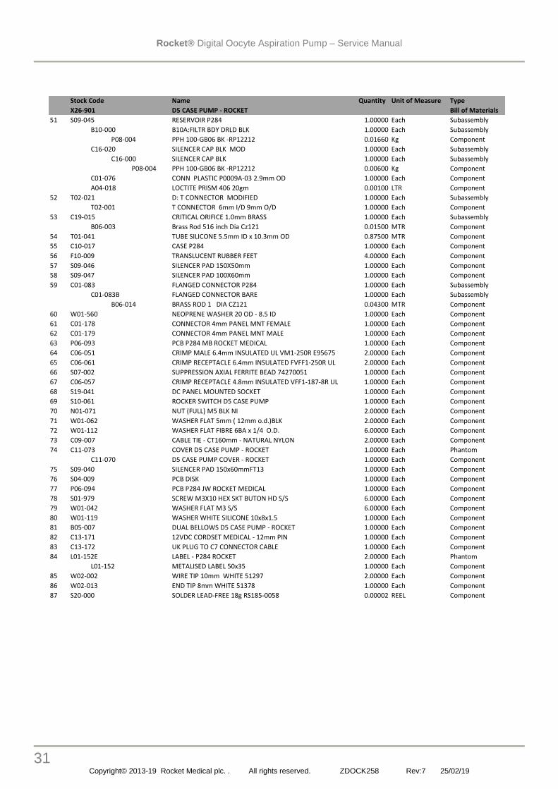
Stock Code Name Quantity Unit of Measure Type
X26-901 D5 CASE PUMP - ROCKET Bill of Materials
51 S09-045 RESERVOIR P284 1.00000 Each Subassembly
B10-000 B10A:FILTR BDY DRLD BLK 1.00000 Each Subassembly
P08-004 PPH 100-GB06 BK -RP12212 0.01660 Kg Component
C16-020 SILENCER CAP BLK MOD 1.00000 Each Subassembly
C16-000 SILENCER CAP BLK 1.00000 Each Subassembly
P08-004 PPH 100-GB06 BK -RP12212 0.00600 Kg Component
C01-076 CONN PLASTIC P0009A-03 2.9mm OD 1.00000 Each Component
A04-018 LOCTITE PRISM 406 20gm 0.00100 LTR Component
52 T02-021 D: T CONNECTOR MODIFIED 1.00000 Each Subassembly
T02-001 T CONNECTOR 6mm I/D 9mm O/D 1.00000 Each Component
53 C19-015 CRITICAL ORIFICE 1.0mm BRASS 1.00000 Each Subassembly
B06-003 Brass Rod 516 inch Dia Cz121 0.01500 MTR Component
54 T01-041 TUBE SILICONE 5.5mm ID x 10.3mm OD 0.87500 MTR Component
55 C10-017 CASE P284 1.00000 Each Component
56 F10-009 TRANSLUCENT RUBBER FEET 4.00000 Each Component
57 S09-046 SILENCER PAD 150X50mm 1.00000 Each Component
58 S09-047 SILENCER PAD 100X60mm 1.00000 Each Component
59 C01-083 FLANGED CONNECTOR P284 1.00000 Each Subassembly
C01-083B FLANGED CONNECTOR BARE 1.00000 Each Subassembly
B06-014 BRASS ROD 1 DIA CZ121 0.04300 MTR Component
60 W01-560 NEOPRENE WASHER 20 OD - 8.5 ID 1.00000 Each Component
61 C01-178 CONNECTOR 4mm PANEL MNT FEMALE 1.00000 Each Component
62 C01-179 CONNECTOR 4mm PANEL MNT MALE 1.00000 Each Component
63 P06-093 PCB P284 MB ROCKET MEDICAL 1.00000 Each Component
64 C06-051 CRIMP MALE 6.4mm INSULATED UL VM1-250R E95675 2.00000 Each Component
65 C06-061 CRIMP RECEPTACLE 6.4mm INSULATED FVFF1-250R UL 2.00000 Each Component
66 S07-002 SUPPRESSION AXIAL FERRITE BEAD 74270051 1.00000 Each Component
67 C06-057 CRIMP RECEPTACLE 4.8mm INSULATED VFF1-187-8R UL 1.00000 Each Component
68 S19-041 DC PANEL MOUNTED SOCKET 1.00000 Each Component
69 S10-061 ROCKER SWITCH D5 CASE PUMP 1.00000 Each Component
70 N01-071 NUT (FULL) M5 BLK NI 2.00000 Each Component
71 W01-062 WASHER FLAT 5mm ( 12mm o.d.)BLK 2.00000 Each Component
72 W01-112 WASHER FLAT FIBRE 6BA x 1/4 O.D. 6.00000 Each Component
73 C09-007 CABLE TIE - CT160mm - NATURAL NYLON 2.00000 Each Component
74 C11-073 COVER D5 CASE PUMP - ROCKET 1.00000 Each Phantom
C11-070 D5 CASE PUMP COVER - ROCKET 1.00000 Each Component
75 S09-040 SILENCER PAD 150x60mmFT13 1.00000 Each Component
76 S04-009 PCB DISK 1.00000 Each Component
77 P06-094 PCB P284 JW ROCKET MEDICAL 1.00000 Each Component
78 S01-979 SCREW M3X10 HEX SKT BUTON HD S/S 6.00000 Each Component
79 W01-042 WASHER FLAT M3 S/S 6.00000 Each Component
80 W01-119 WASHER WHITE SILICONE 10x8x1.5 1.00000 Each Component
81 B05-007 DUAL BELLOWS D5 CASE PUMP - ROCKET 1.00000 Each Component
82 C13-171 12VDC CORDSET MEDICAL - 12mm PIN 1.00000 Each Component
83 C13-172 UK PLUG TO C7 CONNECTOR CABLE 1.00000 Each Component
84 L01-152E LABEL - P284 ROCKET 2.00000 Each Phantom
L01-152 METALISED LABEL 50x35 1.00000 Each Component
85 W02-002 WIRE TIP 10mm WHITE 51297 2.00000 Each Component
86 W02-013 END TIP 8mm WHITE 51378 1.00000 Each Component
87 S20-000 SOLDER LEAD-FREE 18g RS185-0058 0.00002 REEL Component
Royston Road
Byfleet
Surrey, KT14 7NY
United Kingdom

Rocket® Digital Oocyte Aspiration Pump – Service Manual
32 Copyright© 2013-19 Rocket Medical plc. . All rights reserved. ZDOCK258 Rev:7 25/02/19
17. Parts List – PCB Assembly Main PCB
Front Panel PCB (Jocky Wheel)


