U-Line Corporation www.U-LineService.com Phone (414) 354-0300 • FAX (414) 354-7905 Service & Parts Tech Lines Phone (800) 779-2547 • FAX (414) 354-5696 U-Line Corporation PO Box 245040 Milwaukee, WI 53224-9540 U-Line Corporation 8900 North 55th Street Milwaukee, WI 53223 SERVICE AND P ARTS MANUAL Models 95 Icemaker 98 Icemaker BI15 Icemaker 15R 15 Wine Captain Combo 75 Frost Free Combo 75A 75AD 75 Wine Captain 75 Freezer 75R 75RF 75 Bev Combo 29 Frost Free Combo 29A 29AD 29R 29 Wine Captain SP18 M A D E I N T H E U S A R R C
This Service Manual has been written to cover product manufactured with HFC-134a.Units previously manufactured with CFC-12 will, however, be in service for many years.
SERVICING CFC-12 SYSTEMSU-Line Corporation has not approved the use of any “drop in” replacements for CFC-12.U-Line has also not approved the process of converting a CFC-12 system to any othertype of refrigerant.
POTENTIAL PROBLEMS WITH HFC-134AHFC-134A compressors will be received with a synthetic based ester oil charge. Thehygroscopic (water attraction) property of ester oil is many times greater than that ofthe mineral oils previously used with CFC-12. High system moisture causes the forma-tion of acids and alcohol which can damage the compressor. Systems should not be leftopen for more than fifteen (15) minutes at any time as humidity from the air will entersystem. To assure system dehydration, the system should be pulled down to 100microns and vacuum pump oil (mineral oil) must not be allowed to enter then system.
Cleanliness of the system will be extremely important. The presence of residues (chlori-nated or greasy residues, mineral oil, or impurities) can lead to capillary tube restric-tions, oil return problems and compressor damage. Flux must not be used on brazedjoints.
Warranty StatementOn 11-1-98, U-Line Corporation modified the warranty provided with our units. We havesignificantly improved the coverage of the sealed system in years two through five of theunit’s life. The new warranty covers parts and labor for one year from the date of pur-chase. In years two through five, from the date of purchase, the warranty covers partsand labor for the entire sealed system. The sealed system consists of the compressor,condenser, evaporator, heat exchanger, dryer, hot gas bypass-valve and all connectingtubing.
This decision reflects our continuing commitment to strive to maintain the leadershipposition within the under counter refrigeration and ice making industry whether that bethrough design, product innovation, or enhanced consumer warranties. This decisionreinforces the confidence that U-Line has in the performance and reliability of our prod-ucts.
Our previous warranty covered parts and labor for one year from the date of purchaseplus four additional years for the compressor, part only.
The new, modified warranty applies only to units shipped after 11-1-98. All unitsshipped before 11-1-98 have the previous warranty.
PRODUCTS SHIPPED BEFORE 11-1-98 - Warranty covers parts and labor for one yearfrom the date of purchase, plus four additional years for the compressor (part only).
PRODUCTS SHIPPED AFTER 11-1-98 - Warranty covers parts and labor for one yearfrom the date of purchase and covers parts and labor for the entire sealed system forfive years.
DETERMINING SHIP DATESIn order to assure that U-Line is Y2K compliant, we have recently completed a majorcomputer system modification. The new computer system has lead to changes in theway we operate in most areas of the company. You’ll soon notice that our packing listsare different, our invoices are different, our checks are different, and more. The changethat will impact you the most is the change in serial numbers.
With the new computer system, our serial number format has changed. There are somedefinite advantages that go with the new format, such as being able to tell the monthand year in which the unit was produced.
The new serial number format breaks the number down into four segments. A typicalserial number is 047413-06-0100. The first segment 04, represents the year that theunit was made. The second segment 7413, represents the shop order number. Thiscan be a three or four digit number. Order number 7413 is assigned for ModelWH95TP units. The third segment – 06 represents the month that the unit was made.The forth segment – 0100 represents a sequence of numbers that is used internally atU-Line Corporation.
5
U-Line Corporation warrants each U-Line product to be free from defects in materialsand workmanship for a period of one year from the date of purchase; and warrants thesealed system (consisting of the compressor, the condenser, the evaporator, the hot gasbypass valve, the dryer and the connecting tubing) in each U-Line product to be free fromdefects in materials and workmanship for a period of five years from the date of pur-chase. During the initial one-year warranty period for all U-Line products U-Line shall: (1)at U-Line’s option, repair any product or replace any part of a product that breaches thiswarranty; and (2) for all Marine, RV and Domestic U-Line products sold and serviced inthe United States (including Alaska and Hawaii)and Canada, U-Line shall cover the laborcosts incurred in connection with the replacement of any defective part. During yearstwo through five of the warranty period for the sealed system, U-Line shall:. (1) repairor replace any part of the sealed system that breaches this warranty; and (2) for allMarine, RV and Domestic U-Line products sold and serviced in the United States (includ-ing Alaska and Hawaii)and Canada, U-Line shall cover the labor costs incurred in connec-tion with the replacement of any defective part of the sealed system. All other charges,including transportation charges for replacements under this warranty and labor costsnot specifically covered by this warranty, shall be borne by you. This warranty is extend-ed only to the original purchaser of the U-Line product. The Product Registration Cardincluded with the product should be promptly completed by you and mailed back toU-Line or you can register on-line at www.U-LineService.com.
The following are excluded from this limited warranty: installation charges; damagescaused by disasters or acts of God, such as fire, floods, wind and lightening; damagesincurred or resulting from shipping, improper installation, unauthorized modification, ormisuse/abuse of the product; customer education calls; food loss/spoilage; door andwater level adjustments (except during the first 90 days from the date of purchase);defrosting the product; adjusting the controls; door reversal; or cleaning the condenser.
If a product defect is discovered during the applicable warranty period, you must prompt-ly notify either the dealer from whom you purchased the product or U-Line at P.O. Box23220, Milwaukee, Wisconsin 53223 or at 414-354-0300. In no event shall suchnotification be received later than 30 days after the expiration of the applicable warrantyperiod. U-Line may require that defective parts be returned, at your expense, to U-Line’sfactory in Milwaukee, Wisconsin, for inspection. Any action by you for breach of warran-ty must be commenced within one year after the expiration of the applicable warrantyperiod.
This limited warranty is in lieu of any other warranty, express or implied, including, butnot limited to any implied warranty of merchantability or fitness for a particular pur-pose; provided however, that to the extent required by law, implied warranties areincluded but do not extend beyond the duration of the express warranty first set forthabove. U-Line’s sole liability and your exclusive remedy under this warranty is set forthin the initial paragraph above. U-Line shall have no liability whatsoever for any inciden-tal, consequential or special damages arising from the sale, use or installation of theproduct or from any other cause whatsoever, whether based on warranty (express orimplied) or otherwise based on contract, tort or any other theory of liability.
Some states do not allow limitations on how long an implied warranty lasts or the exclu-sion or limitation of incidental or consequential damages, so the above limitations maynot apply to you. This warranty gives you specific legal rights, and you may also haveother rights which vary from state to state.
LIMITED WARRANTY
Service and Parts Manual
6
This is the safety alert symbol. It is used to alert you to potential personalinjury hazards. Obey all safety messages that follow this symbol to avoid possible injury or death.
!
DANGER indicates an imminently hazardous situation which, if not avoided,will result in death or serious injury.
DANGER !!
WARNING indicates a potentially hazardous situation which, if not avoided,could result in death or serious injury.
! !
CAUTION indicates a potentially hazardous situation which, if not avoided,may result in minor or moderate injury.
!
CAUTION used without the safety alert symbol indicates a potentially hazardous situation which, if not avoided, may result in property damage.
IMPORTANT indicates installation, operation or maintenance informationwhich is important but not hazard-related.
7
Do not attempt to service or repair the unit until you have read the entire procedure.Safety items throughout this manual are labeled with Warning or Caution.
SAFETY PRECAUTIONS
Risk of child entrapment. Before you throw away an old refrigerator or freezer: Take off the doors, leave shelves in place so that children may noteasily climb inside.
DANGER !!
• Never attempt to repair or perform maintenance on the unituntil the electricity has been disconnected.
• Altering, cutting of power cord, removal of power cord, removalof power plug, or direct wiring can cause serious injury, fireand/or loss of property and/or life and will void the warranty.
DANGER !!
• Do not lift unit by door handle.• Never use an ice pick or other sharp instrument to help speed up defrost-
ing. These instruments can puncture the inner lining or damage the cool-ing unit.
• Failure to clean the condenser every three months can cause the unit tomalfunction. This could void the warranty.
• Never install the unit behind closed doors. Be sure front grille is free ofobstruction. Obstructing free air flow can cause the unit to malfunction,and may void the warranty.
Service and Parts Manual
8
When submitting claims for warranty payment, please follow these guidelines.
You can use any form you would normally use to bill your customer (your own computergenerated form, Narda, USA, etc.).
The model and serial number MUST be on the claims. Claims will not be paid without amodel and serial number.
If you work on more than one unit per service call please submit a separate claim foreach unit.
We track all defects through warranty claims, so please be specific on what the repairwas. If it is a system leak, please specify where the leak was.
Please be sure the claim is legible. If the claim form cannot be read, it will be returned,unpaid.
U-Line will not cover part or labor claims for the replacement of a complete ice makerassembly. All ice maker parts are available as replacement parts and are stocked in ourinventory. Remember: we do not pay customer education calls. Door and water leveladjustments are 90 day warranties only.
If you are changing out a unit please supply the model and serial number of both units(the unit being replaced and the new unit) and the R.A. number.
If a copy of the Proof of Purchase/Install is not available at the site, the technicianshould record he following information on the Labor Invoice:
• The name of the selling Dealer
• The date of purchase/installation
• The Order or Invoice number (if available)
• The type of document the technician saw i.e. Store Receipt, Closing Papers,Sign-Off of Building Permit, Final Walk Through, etc.
At U-Line, parts and labor claims are paid separately. Included in labor would be freonand recovery charges, all other parts are handled by the parts department. We requirethat some parts be returned to us, so we may return them to our vendor. It will benoted on your packing list if we require you to return the part. If a part is to be returnedplease include a copy of the packing list and a copy of your claim. If the part was pur-chased at one of our part distributors, you must handle the part warranty with that com-pany. For labor payment please send a readable copy of your claim to U-LineCorporation, P.O. Box 245040, Milwaukee WI, 53224-9540, for warranty payment.
WARRANTY CLAIMS PROCEDURE
9
U-line’s warranty does not cover customer education calls. It has been reported that ashigh as 50% of all service calls performed, are customer education calls.
The following guide has been developed to help screen calls on the most common cus-tomer education issues. It can be used by persons scheduling service calls.
The unit is not cold enough!Questions to ask before scheduling a service call —
• Are you familiar with the factory specifications for this unit? (many factors can causethese figures to vary. Ambient temperature, application, amount of use etc.)
• Is the door sealing properly? If the door is not sealed properly, it allows heat into theunit. U-Line's warranty is 90 days for door adjustments.
• Is the condenser clean? U-Line's warranty does not cover cleaning the condenser.• Is the unit behind closed doors? The unit must have free air flow to the front grille.• Did you try turning the temperature control colder? Turning the control knob clock-
wise is colder. Be sure to allow 24 hrs. between temperature control adjustments.• For model 29AD only. Is the defrost timer set to the time of day? When set properly,
the unit will be off, defrosting, between midnight and 3:30 a.m.• For Wine Captain Units and 75 Bev. Is the light on constantly to display the wine?
If the light is on constantly, this could cause the unit to run warmer.
The ice cubes are sticking together!Questions to ask before scheduling a service call —
• Does the unit need to be defrosted? • Is the door sealing properly? This could cause the ice cubes to stick together.• Have you tried to ruffle the the ice bucket? If the ice sits without being used, it will
tend to stick together. Shaking the bucket will usually break apart the ice cubes. Ifthe ice has been sitting for a long time, we recommend dumping the bucket and mak-ing fresh ice.
CUSTOMERCOMPLAINT
CUSTOMERCOMPLAINT
GUIDE FOR SCREENING CALLS
Service and Parts Manual
10
No ice or not enough ice!Questions to ask before scheduling a service call —
• Is the temperature control set to the warmest setting? The unit will produce the mostice when set at the warmest setting. Let the unit run overnight.
• Is the ice maker bin arm down? When the arm is up, it will not make ice.• Is the door sealing properly? U-Line's warranty is 90 days for door adjustments.• Does the water level need to be adjusted? U-Line's warranty is 90 days for water level
adjustments.
The unit is frosting up!Questions to ask before scheduling a service call —
• Are you familiar with the defrost technology of the unit?Defrost Technology Model NumbersManual Defrost Combo 75A, Combo 29A, 95, 98, 75, BI15Cycle Defrost 75R, 29R, 15R, 75WC, 29WC, 15WC, BC85DTAuto Defrost 29AD, 75AD, 75 Bev (periodic manual defrost may be needed)Frost Free Combo 75FF, Combo 29FF
• Is the door sealing properly? U-Line's warranty is 90 days for door adjustments.• Has the door been left open?• Is the unit in an application of heavy usage? Heavy usage or high ambient tempera-
tures will cause a unit to frost up.
Water is leaking out of the back of the unit!Questions to ask before scheduling a service call —
• Have you checked the connection at the water solenoid valve? U-Line's warranty doesnot cover installation adjustments.
The light on my Wine Captain/75 Bev never shuts off!Questions to ask before scheduling a service call —
• Did you turn the on/off switch near the base of the unit? The on/off switch is for thelight operation only. When the switch is in the off position, the light will turn on onlywhen the door is open. When the switch is in the on position, the light will be on con-stantly to display the wine. To shut the unit off, turn the temperature control all theway counterclockwise.
CUSTOMERCOMPLAINT
CUSTOMERCOMPLAINT
CUSTOMERCOMPLAINT
CUSTOMERCOMPLAINT
11
Normal Vapor/Compression Cycle Refrigeration• Refrigerant is pumped from the compressor to the condenser as a high pressure,
high temperature vapor.
• As the refrigerant cools in the high pressure condenser, the vapor condenses to liquid.During this phase change, a great amount of heat is rejected with the help of the con-denser fan.
• The liquid then flows to the dryer where it is strained and filtered.
• From the dryer, the refrigerant flows through the capillary tube which meters the liquidrefrigerant to the evaporator. The pressure of the refrigerant is reduced to the evapo-rating or low side pressure.
• The reduction of pressure on the liquid refrigerant causes it to boil or vaporize until itreaches saturation temperature. As the low temperature refrigerant passes throughthe evaporator coil, it continues to absorb a lot of heat, causing the boiling action tocontinue until the refrigerant is completely vaporized. It is during this phase changethat the most heat is absorbed (the cooling takes place) in the refrigerator.
• The refrigerant vapor leaving the evaporator travels through the suction line to thecompressor inlet. The compressor takes the low pressure vapor and compresses it,increasing both pressure and temperature. The hot high pressure gas is pumped outthe discharge line and into the condenser. The cycle continues.
CAPILLARY TUBE
DRYER
CONDENSER
COMPRESSOR
EVAPORATOR
UL183-1
REFRIGERATION SYSTEMS
Service and Parts Manual
12
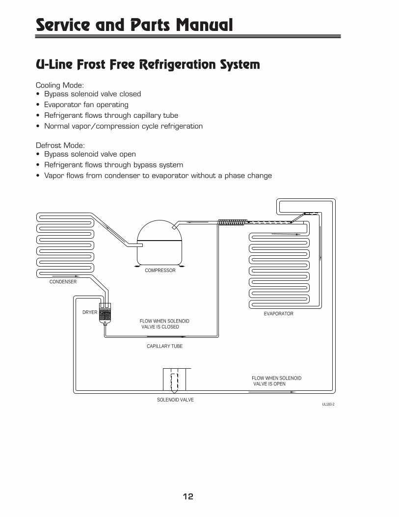
U-Line Frost Free Refrigeration SystemCooling Mode:• Bypass solenoid valve closed• Evaporator fan operating• Refrigerant flows through capillary tube• Normal vapor/compression cycle refrigeration
Defrost Mode:• Bypass solenoid valve open• Refrigerant flows through bypass system• Vapor flows from condenser to evaporator without a phase change
SOLENOID VALVE
CAPILLARY TUBE
VALVE IS CLOSEDFLOW WHEN SOLENOID
DRYER
CONDENSER
COMPRESSOR
EVAPORATOR
VALVE IS OPENFLOW WHEN SOLENOID
UL183-2
13
Compressor/Electrical Specifications
Compressor PinsTo measure start winding resistance, measure across the C-S pins.To measure run winding resistance, measure across the C-R pins. These pins shouldnever measure any resistance to ground. This would indicate a shorted compressor.
115 VOLT Ice Maker Heater Resistance: 80 OHMS115 VOLT Water Valve Coil Resistance: 335 OHMS
C
S R
OVERLOAD PROTECTOR
STARTING RELAY
RELAY COVERUL183-3
EMI ER
Service and Parts M
anual
14
System Suction Suction Compressor Condenser Capillary Evaporator WattageCondition Pressure Line Discharge Tube
Normal Normal Slightly below Very hot Very hot Warm Cold Normalroom
temperature
Overcharge Higher than Very cold Slightly warm Hot to warm Cool Cold Higher thannormal may frost to hot normal
heavily
Undercharge Lower than Warm - near Hot Warm Warm Extremely cold Lower thannormal room near inlet - normal
temperature Outletbelow roomtemperature
Partial Somewhat Warm - near Very hot Top passes Room Extremely cold Lower thanRestriction lower than room warm - temperature near inlet - normal
normal-in temperature Lower passes (cool) or Outletvacuum cool colder below room
(near room temperaturetemperature) backing updue to liquid
Complete In deep Room Room Room Room No Lower thanRestriction vacuum temperature temperature temperature temperature refrigeration normal
(cool) (cool) (cool) (cool)
No 0 PSIG Room Cool Room Room No Lower thanGas to temperature to temperature temperature refrigeration normal
25" (cool) hot (cool) (cool)
Refrigeration System Diagnosis Guide
15
Ice Maker Operating Cycles1. FREEZE CYCLE
A. Temperature control terminals 2 and 3 are closedB. Power to the compressorC. Power to the condenser fan
2. HARVEST-1 CYCLE
A. Temperature control terminals 2 and 3 are open - 2 and 1 closeB. No power to the compressor or condenser fanC. If bin arm is down, power goes through bin arm switch to ice maker motorand mold heater. If bin arm is up, the ice maker will not harvest.
3. HARVEST-2 CYCLE
A. Ice maker ejector blades reach approximately 2:00 position and camdepresses the hold switch. Power goes through the hold switch to the icemaker motor and mold heater.
B. Ejector blades stall on ice and ice maker motor pulsates until mold heater warms and ice releases.
4. WATER FILL CYCLE
A. Ice maker ejector blades reach approximately 10:00 position and camdepresses the water fill switch.
B. Power to the water valve. Ice maker mold fills.
5. EJECT CYCLE
A. Ejector blades push ice into bucket and stop at 12:00 position.B. Temperature control terminals 2 and 3 have closed during harvest cycle.C. Next freeze cycle begins with power to the compressor and condenser fan.
ICE MAKER OPERATION
Service and Parts Manual
16
Cycle Schematics
HARVEST-1 CYCLE(Hold Switch In Normal Position)
SWITCHLIMIT
orange
black
black black
MOTORMAKER ICE
MOLD HEATER
WATER
SWITCH FILLC NC
MOTOR FAN
LOADOVER
black RELAYSTARTCOMP.
SWITCH OFFON
black
black
blue
black
CONTROL TEMP.
NC
black
orange
3
yellow
2
orange
SWITCH BIN
red NO
1
C
NO
brown
black
white
CSWITCH HOLD
VALVEWATER
ground
UL183-5
FREEZE CYCLE
SWITCHLIMIT
orange
black
black black
MOTORMAKER ICE
MOLD HEATER
WATER
SWITCH FILLC NC
MOTOR FAN
LOADOVER
black RELAYSTARTCOMP.
SWITCH OFF ON
black
black
blue
black
CONTROL TEMP.
NC
black
orange
3
yellow
2
orange
SWITCH BIN
red NO
1
C
NO
brown
black
white
CSWITCH HOLD
VALVEWATER
ground
UL183-4
17
Cycle Schematics
WATER FILL CYCLE
SWITCHLIMIT
orange
black
black black
MOTORMAKER ICE
MOLD HEATER
WATER
SWITCH FILLC NC
MOTOR FAN
LOADOVER
black RELAYSTARTCOMP.
SWITCH OFF ON
black
black
blue
black
CONTROL TEMP.
NC
black
orange
3
yellow
2
orange
SWITCH BIN
red NO
1
C
NO
brown
black
white
CSWITCH HOLD
VALVEWATER
ground
UL183-7
HARVEST-2 CYCLE(Hold Switch In Switched Position)
SWITCHLIMIT
orange
black
black black
MOTORMAKER ICE
MOLD HEATER
WATER
SWITCH FILLC NC
MOTOR FAN
LOADOVER
black RELAYSTARTCOMP.
SWITCH OFF ON
black
black
blue
black
CONTROL TEMP.
NC
black
orange
3
yellow
2
orange
SWITCH BIN
red NO
1
C
NO
brown
black
white
CSWITCH HOLD
VALVEWATER
ground
UL183-6
Service and Parts Manual
18
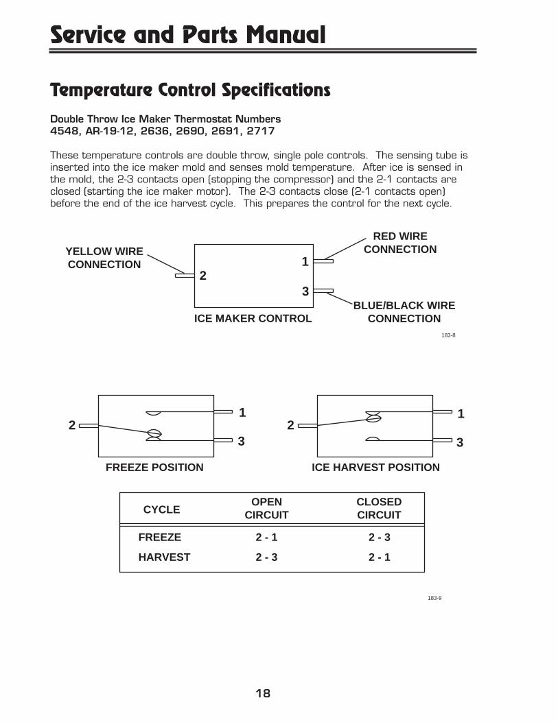
Temperature Control SpecificationsDouble Throw Ice Maker Thermostat Numbers4548, AR-19-12, 2636, 2690, 2691, 2717
These temperature controls are double throw, single pole controls. The sensing tube isinserted into the ice maker mold and senses mold temperature. After ice is sensed inthe mold, the 2-3 contacts open (stopping the compressor) and the 2-1 contacts areclosed (starting the ice maker motor). The 2-3 contacts close (2-1 contacts open)before the end of the ice harvest cycle. This prepares the control for the next cycle.
The function of this switch is to open in the event of an overheating condition. Thisbi-metal thermostat is normally closed and does not initiate the ice harvest cycle.The ice harvest cycle is initiated by a double throw, single pole switch located remote-ly from the ice maker assembly.
28.12
3.00
183-10
Service and Parts Manual
20
Ice Maker Diagnosis Flow Chart
DOES THE UNIT REFRIGERATE?
Sealed System Leak�Electrical Failure�Compressor Failure�Fan Motor Failure�Defrost System Failure
Low Voltage�Voltage Drop�Wiring
Temperature Control Failure�Water Adjustment�Bin Switch Failure
NO
NO
EVERYWHERE
INTERMITTENT
AT 3:00
YE
SN
OA
T 1
2:00
DOES THE UNIT HARVEST ICE�IF THE EJECTOR BLADES ARE�MOVED BY HAND OR WITH A �
WRENCH ?
WHERE DO THE �EJECTOR BLADES�
STOP?
Mold Heater Failure
Solenoid Valve Failure
Ice Motor Failure�Hold Switch Failure�Limit Switch Failure�Binding Cam/Ejector
Water Switch Failure
���IS THERE VOLTAGE AT THE �SOLENOID VALVE TERMINALS�
DURING HARVEST?���
UL183-11
YES
YES
�
21
Redesign DifferentiationThrough our continuous efforts to improve our product line, U-Line Corporation hasmade some changes to the design of Models Combo 29FF and Combo 75FF.
The objective of this section is to assist the service technician in differentiating betweenthe previous design product and the new redesign.
The redesign involves a new compressor, evaporator and heat exchanger, condenser fanmotor, evaporator fan motor, drain trough, timer and power cord.
To address service problems which may exist in earlier designs, we developed a “Field FixKit.” It involves replacing the compressor, dryer, and hot gas valve. It also includesmounting a sheet of insulation to the back panel. Before installing the new compressor,hot gas bypass valve, and dryer, it is imperative that the entire refrigeration system beblown out with nitrogen to remove any excess oil. This kit is to be installed in units withR-134a only starting with serial number 7CF300000 or 2CF300000. Installationinstructions are included in each kit ordered.
The new compressor, a Matsushita Model SD39C replaces the previous compressor, anEmbraco EMI 50 HER.
Both the previous design and the new redesign are detailed in this manual. New designunits and previous design units can be differentiated by the serial numbers. All serialnumbers for the new redesigned units start with a number higher than 600000.(Example: 2CF600001 is a new redesigned Combo 29FF.) Previous design units haveserial numbers which start with 300001, 400001, or 500001. (Example:7CF400001 is a previous design Combo 75FF.)
Pages 45-46 show the parts breakdown for the previous design of the Combo29FF. The parts replaced with the kit are denoted. The wiring diagram for thismodel is on page 36.
Pages 41-42 show the parts breakdown for the previous design of the Combo75FF. The parts replaced with the kit are denoted. The wiring diagram for thismodel is on page 36.
Pages 47-48 show the parts breakdown for the new, redesign of the Combo29FF. The wiring diagram for this model is on page 37. The information for thehybrid redesign of the Combo 29FF can be found in the Échelon Service Manual.
Pages 43-44 show the parts breakdown for the new, redesign of the Combo75FF. The wiring diagram for this model is on page 37.
FROST FREE UNITS
Service and Parts Manual
22
Typical Frost Free Airflow Configuration
Air Flow In At�Evaporator Blade
Air Flow Out At�Evaporator Outlet
Air Passes�Through Fin/Tube�Evaporator
�
Condensate Drains Down Trough Under Evaporator,�Into Drain Cup, And Into Condensate Pan Through�Drain Hose. The Drain Trough Is Warmed During�Defrost By Contact with Evaporator Fins.
UL183-12
23
Disassembly ProceduresModel Combo C075FF1. Disconnect from power source.2. Disconnect ice maker wires in back of unit.3. Remove screws (6) from freezer housing.4. Slide out freezer housing with ice maker unit
attached.5. Remove screws (4) from evaporator cover.6. Slide evaporator cover out of clips (2).
To remove fan blade/motor:1. Disconnect fan wires in the back of unit.2. Remove fan blade by sliding off fan motor
shaft.3. Remove screws (2) from fan motor mount-
ing bracket.4. Remove mounting nuts (2) from fan motor
studs.
To remove evaporator:1. Disconnect copper tubing. Be sure to
reclaim, recycle or recover refrigerant.2. Remove screw from evaporator clip (2).3. Slide out evaporator.
HOUSINGFREEZER
SCREWS (2)
SCREWS (2)
UNITICE MAKER
UL183-13
COVEREVAPORATOR
SCREWS (4)
CLIP
UL183-14
EVAPORATOR
SCREWS (2)
CLIP (2)EVAPORATOR
AND BLADEFAN MOTOR
NUTS (2)FAN MOTOR
UL183-15
Service and Parts Manual
24
Model Combo C029FF1. Disconnect from power source.2. Disconnect ice maker wires in back of unit.3. Remove screws (3) from freezer housing.4. Slide out freezer housing with ice maker unit
attached.5. Remove screws (4) from evaporator cover.6. Slide evaporator cover out of clips (2).
To remove fan blade/motor:1. Disconnect fan wires in the back of unit.2. Remove fan blade by sliding off fan motor
shaft.3. Remove screws (2) from fan motor mount-
ing bracket.4. Remove mounting nuts (2) from fan motor
studs.
To remove evaporator:1. Disconnect copper tubing. Be sure to
reclaim, recycle or recover refrigerant.2. Remove screw from evaporator clip (2).3. Slide out evaporator.
HOUSINGFREEZER
UNITICE MAKER
SCREWS (2)
UL183-16
COVEREVAPORATOR
CLIP
SCREWS (4)
UL183-17
NUTS (2)FAN MOTOR
CLIP (2)EVAPORATOR
EVAPORATOR
SCREWS (2)
AND BLADEFAN MOTOR
UL183-18
25
Model Combo 75RF1. Disconnect from power source.2. Remove freezer door.3. Slide out mullion.4. Remove screws.
To remove fan blade/motor:1. Disconnect fan wires in the back of unit.2. Remove fan blade by sliding off motor shaft.3. Remove screws (2) from mounting bracket.4. Remove nuts from fan motor studs.
To remove evaporator:1. Recover all refrigerant.2. Disconnect copper tubing.3. Remove mounting screws (4) from
evaporator.4. Slide out evaporator.
EVAPORATOR COVER
MULLION
UL183-19
EVAPORATOR
FAN & MOTOR
UL183-20
Service and Parts Manual
26
NEVER attempt to repair or perform maintenance on the unit until the mainelectrical power has been disconnected.
1. Will not eject ice (water frozen)Cause Remedy
■ Control setting too cold ■ Adjust control warmer (counterclockwise)■ Control defective (1-2 contacts open) ■ Replace control■ Bin switch defective ■ Replace bin switch■ Limit switch defective (open) ■ Replace limit switch■ Ice maker assembly motor stalled ■ Replace motor■ Broken wire in ice maker circuit ■ Repair or replace wiring■ Water soaked cabinet insulation ■ Replace foamed cabinet assembly■ Dirty condenser ■ Clean condenser
2. Will not fill with waterCause Remedy
■ Water supply valve closed ■ Open water supply valve■ Water switch defective (open) ■ Replace water switch■ Solenoid valve defective ■ Replace solenoid valve■ Fill tube outlet frozen ■ Replace solenoid valve and defrost fill tube■ Broken wire in water fill circuit ■ Repair or replace wiring
3. Will not stop making iceCause Remedy
■ Bin switch defective (closed) ■ Replace bin switch■ Bin arm binding ■ Lubricate bin arm pivot points or loosen
bin arm lever screw
4. Water will not stop fillingCause Remedy
■ Water switch defective (closed) ■ Replace water switch■ Solenoid valve defective ■ Replace solenoid valve■ Stalled ice maker motor ■ Replace motor■ Temperature control defective. ■ Replace temperature control
Ice maker is in continuous harvestcycle (contacts 1-2 closed)
5. Ejector blades will not stop turningCause Remedy
■ Control defective (1-2 contacts will ■ Replace controlnot open)
■ Hold switch defective ■ Replace hold switch■ Defective wiring ■ Repair or replace wiring■ Short in mold heater ■ Replace heater
DANGER !!
TROUBLESHOOTING
27
6. Low ice productionCause Remedy
■ Control set too cold ■ Adjust control warmer (counterclockwise)■ Fan motor stalled ■ Replace fan motor■ Ice cubes too large ■ Lower water fill adjustment■ Dirty condenser ■ Clean condenser■ Bypass valve stuck open ■ Replace bypass valve
7. Not freezing (compressor and fan motors operating)Cause Remedy
■ Little or no frost pattern on evaporator ■ Check for sealed system leak or restriction■ Bypass valve stuck open ■ Replace bypass valve
8. Not freezing (compressor not operating - fans operating)Cause Remedy
9. Not freezing (compressor and fans not operating)Cause Remedy
■ On-Off switch defective (open) ■ Replace On-Off switch■ Hold switch defective (open) ■ Replace hold switch■ Control defective (2-3 contacts open) ■ Replace control■ Broken wire in freeze circuit ■ Repair or replace wiring■ Power cord not plugged in ■ Plug in power cord■ On-Off switch in off position ■ Put switch in on position■ Ejector blades not in the freeze ■ Manually advance ejector blades to the
position (12:00) 12:00 position (test ice maker andlimit switch)
10. Compressor overheatingCause Remedy
■ Condenser air flow restricted ■ Remove restriction (clean condenser and grille)
■ Condenser fan blade obstructed ■ Remove blade restriction■ Condenser fan motor stalled ■ Replace fan motor■ Defective compressor ■ Replace compressor
11. Compressor will not stop operatingCause Remedy
■ Control set too cold ■ Adjust control warmer (counterclockwise)■ Control defective (2-3 contacts will not ■ Replace control
open)■ Control sensing bulb not sensing ■ Fully insert bulb into ice maker tube,
mold temperature routing bulb away from compressordischarge tube
■ Evaporator fan stalled ■ Remove obstruction or replace motor
12. Water leak (under unit)Cause Remedy
■ Water supply line leaking at solenoid ■ Tighten or replace fittingvalve inlet
■ Water line leaking at solenoid valve outlet ■ Replace water line and fitting
Service and Parts Manual
28
■ Water line leaking at fill tube ■ Tighten clamp or fill tube replace fill tube assembly
■ Defrost drain line not in drain pan ■ Position drain line in drain pan■ Crack in water line ■ Replace water line
13. Water leak (inside unit)Cause Remedy
■ Ice maker assembly fill cup obstructed ■ Remove obstruction. ■ Fill ice cup and fill tube out of alignment ■ Align fill tube and fill cup■ Water level too high ■ Adjust water level■ Defrost drain plugged ■ Ice in drain trough (refer to #16)
14. Excessive frost build-upCause Remedy
■ Door gasket not sealing properly ■ Adjust door hinges or replace door gasket■ Door out of alignment ■ Adjust door hinges■ Water soaked cabinet insulation ■ Replace foamed cabinet assembly
(factory repair only)■ Light stays on when door is closed ■ Repair or adjust light bracket
15. NoisyCause Remedy
■ Copper refrigeration tube touching cabinet ■ Carefully adjust tubing■ Fan blade touching shroud ■ Adjust fan mounting or shroud■ Fan blade obstruction (wiring, foam ■ Remove obstruction
insulation, packaging material)
16. Ice build-up in drain trough or drainage problem (see page 20)Cause Remedy
■ Obstructed drain cup or tube ■ Clear obstruction■ Evaporator not touching drain trough ■ Reposition evaporator to contact drain
trough along entire length■ Kinked drain tube ■ Reroute drain tube■ Drain trough spout and drain cup ■ Align drain trough and drain cup
■ Ice bucket not fully inserted ■ Push ice bucket in place■ Temperature control set too cold ■ Adjust control to warmer setting
(counterclockwise)■ Air leak at evaporator cover ■ Seal cover with RTV
REPLACEMENT PARTS: Use only genuine U-Line replacement parts. The use of nonU-Line parts can reduce ice rate, cause water to overflow from ice maker mold, dam-age the unit, and may void the warranty.
29
EMBRACO
MATSUSHITA
ASSEMBLY
POWER CORD
KGS
BLUE
GREEN
WHITE
BLUE
CAPACITOR
GREEN
BLUE
BLUE
WHITE
COMPRESSOR
8
RELAY
3
OVERLOAD
BLUE
RELAY
OVERLOAD 2
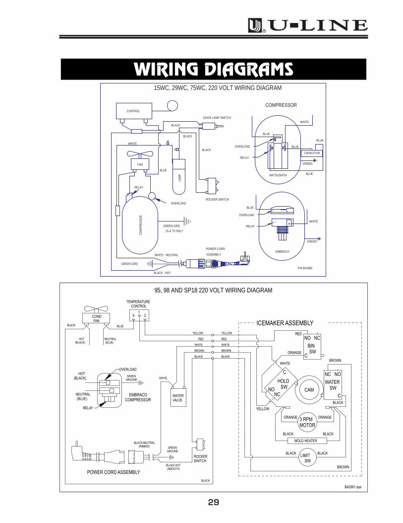
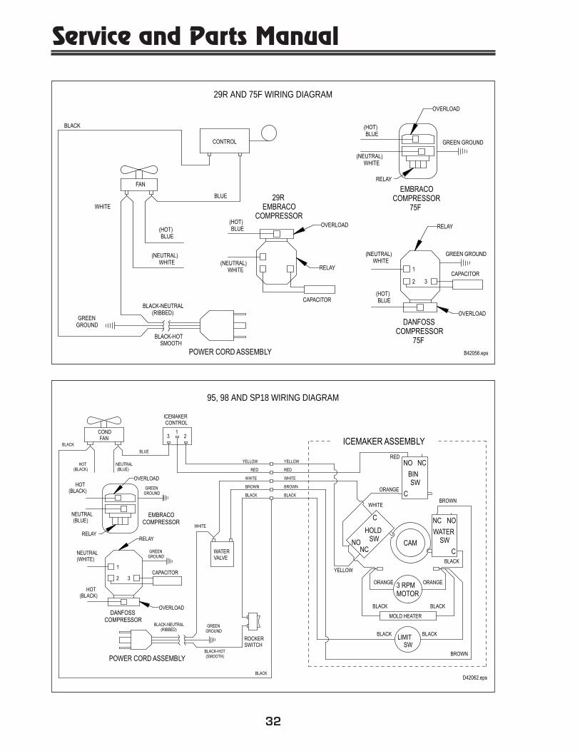
15WC, 29WC, 75WC, 220 VOLT WIRING DIAGRAM
CO
MPR
ESSO
R
15 & 75 ONLY
GREEN GRD.
WHITE - NEUTRAL
GREEN GRD.
BLACK - HOT
OVERLOAD
BLACK
LAM
P
BLACK
RELAY
BLUE
FAN
WHITE
BLACK
P/N B41885
ROCKER SWITCH
DOOR LAMP SWITCH
CONTROL
B42061.eps
BLACK
POWER CORD ASSEMBLY
GREENGROUND
BLACK-HOT(SMOOTH)
BLACK-NEUTRAL(RIBBED)
ROCKERSWITCH
BLACK
RED
YELLOW
BROWN
WHITE
WATERVALVE
BLACK
BLACK
3 RPMMOTOR
LIMITSW
MOLD HEATER
C
NO NC
BINSW
NC NO
WATERSW
CCAM
NCNO
C
HOLDSW
ORANGE
RED
BLACK BLACK
BLACK
ORANGE ORANGE
YELLOW
WHITEBROWN
ICEMAKER ASSEMBLY
RED
YELLOW
BROWN
WHITE
BLACK
BLUE
BROWN
WHITE
TEMPERATURECONTROL
BLACK
CONDFAN
123
NEUTRAL(BLUE)
HOT(BLACK)
HOT(BLACK)
RELAY
EMBRACOCOMPRESSOR
OVERLOAD
NEUTRAL(BLUE)
GREENGROUND
95, 98 AND SP18 220 VOLT WIRING DIAGRAM
WIRING DIAGRAMS
Service and Parts Manual
30
YELLOW
BROWN
WHITE
WHITE
BLACK
RED
WHITE
LOADOVER RELAY
COMPRESSOR
BLACK
GREEN
GREEN
BLACK
SWITCHDOOR
CONDENSER
CONTROLTEMPERATURE
FAN
WHITE
BLACK
BLACK
ON/OFF SWITCH
BLACK
BLACK
BLACK
BLU
E
LAMP
BLACK WHITE
SOLENOIDWATER
WHITE
2
1
3 BLACK
ICEMAKER ASSEMBLY
SWLIMIT
BLACK
WHITE (RIBBED)
KGS
BLACK BLACK
MOLD HEATER
MOTOR3 RPM
RED
BROWN
OR
ANG
EBL
ACK
NO
YELL
OW
SWHOLD
CAMNC
C
WHITE
BLACK
RED
YELLOW
ORANGE
BLAC
KO
RAN
GE
BLACK
BROWN
SWWATER
C
NC NO
SWBIN
NC
C
NO
COMBO 75A 220 VOLT WIRING DIAGRAM (WITH BASE MOUNTED CONTROL)
P/N 41886
NO
ICEMAKER ASSEMBLY
BLACK
LOADOVER
COMPRESSOR
GREEN
BLACK
BLACK WHITE
GREEN
ON/OFF SWITCH
RELAY
CONDENSER
BLACK
WHITE
FAN
BLACK
BLU
E
BLACK
SWITCHDOOR
BLACK WHITE
LAMP
1BLACK
CONTROLTEMPERATURE 2
BLACK
3
SOLENOIDWATER
BLAC
K
YELL
OW
BLACK
BROWN
WHITE
WHITE
YELLOW
BLACK
RED
YELLOW
WHITE
BROWN
RED
BLACK
BLAC
K
EMBRACO
WHITE (RIBBED)
BLACK
MOLD HEATER
SWLIMIT BLACK
GREEN
WHITE
MATSUSHITA
BLACK
SWBIN
BROWN
BLACK
MOTOR
3 RPM
OR
ANG
E
OR
ANG
E
ORANGE
C
CAMNC
SWHOLD
C SWWATER
NONC
C
RED
NO NC
BLUE
CAPACITOR
BLUE
GREEN
BLUE
WHITE
RELAY
COMPRESSOR
OVERLOAD
BLACK
RELAY
OVERLOAD
8
23
COMBO 75A WIRING DIAGRAM
P/N A41881
31
MATSUSHITA
EMBRACO
WHITE
WHITE
WHITE
WHITE
WHITE
BLACK
BLUE
BLUE
GREEN
WHITE
BLUE
GREEN
CAPACITOR
BLUE
WHITE
BLUE
COMPRESSOR
8
RELAY
3
OVERLOAD
BLUE
RELAY
OVERLOAD 2
ASSEMBLY POWER CORD
Com
pres
sor
JunctionMolded WHITE (NEUTRAL)
GREEN
BLACK (HOT)
RELAY
OVERLOAD
Fan
Control
BLACK
BLACK
MOTOR
TIMER
DEFROST
43 2 1
P/N A41857
MODEL 29AD WIRING DIAGRAM WITH MALLORY DEFROST TIMER
COMBO 75FF (New Design; starting S/N 7CF600000) WIRING DIAGRAM
BLACK
WHITE (RIBBED)
BLACK
SOLENOIDBYPASS
TIMER
BLACK GREEN
WHITE
GREEN
BLACK
ON/OFF SWITCH
OVERLOAD
COMPRESSOR
WH
ITE
WHITE
RELAY
PURPLE
BLACK
FAN
BLACK
2 3
1
BLACK
BLACK
SOLENOIDWATER
13 4 2
BLACK
PURPLE
FAN
WHITE
WHITE
BLUE
WHITEWHITE
BROWN BROWN
BLACK
REDYELLOW
BLACK
REDYELLOW
SWLIMIT BLACKBLACK
POWER CORD
ICEMAKER ASSEMBLY
P/N 41969
YELL
OW BROWN
MOTOR3 RPM
MOLD HEATER
OR
ANG
EBL
ACK
NO
CNC
SWHOLD
CAM
OR
ANG
EBL
ACK
BLACK
NONC
C SWWATER
RED
ORANGE SWBIN
C
NCNO
BLUE
WHITE
EMBRACO
MATSUSHITA
CAPACITOR
BLACK
BLUE
WHITE
COMBO 29FF (New Design; starting S/N 2CF600000) WIRING DIAGRAM
OVERLOAD
RELAY
BLACK
COMPRESSOR
Service and Parts Manual
38
ASSEMBLY
POWER CORD
OVERLOAD
OVERLOAD
CAPACITOR
GREEN GROUND15WC & 75WC ONLY
GREEN GROUND15WC & 75WC ONLY
RELAY
RELAY
NEUTRAL(WHITE)
NEUTRAL(WHITE)
HOT(BLUE)
HOT(BLUE)
DANFOSSCOMPRESSOR
EMBRACOCOMPRESSOR
15WC, 29WC, 75WC, 75 BEV WIRING DIAGRAM
WHITE - NEUTRAL
NEUTRAL(WHITE)
WHITE
Fan
BLUE
Control
BLACK
BLACK
BLACKWHITE
HOT(BLUE)
BLACK - HOT
GREEN GRD.BLACK
BLACK
RockerSwitch
Lam
p
P/N B41860_E
DoorLampSwitch
39
220 Volt Part Conversion ListAll parts listed in the SERVICE and PARTS MANUAL are 110/115 volt. This documentis a conversion list for the applicable 220 volt part.
These 220 volt parts are used on the 95, 98 and BI15 Ice makers, the PBCM 95/98Tank Model Ice Makers, Combo 29A, Combo 75A plus the 75WC, 29WC, and 15WCWine Captains.
1847-1-SS Hinge Plate Top X X X1847-2-SS Hinge Plate Bottom X X X1848A-S-SS Top Hinge X X X11624-1-S-BLK* Bottom Hinge X X X42021 Handle X X42019 Handle X X X41995-1 Handle X41995-3 Handle X242-1-SS Top Hinge Right X X X X X245-1-SS Bottom Hinge Right X X X X X
Service and Parts Manual
40
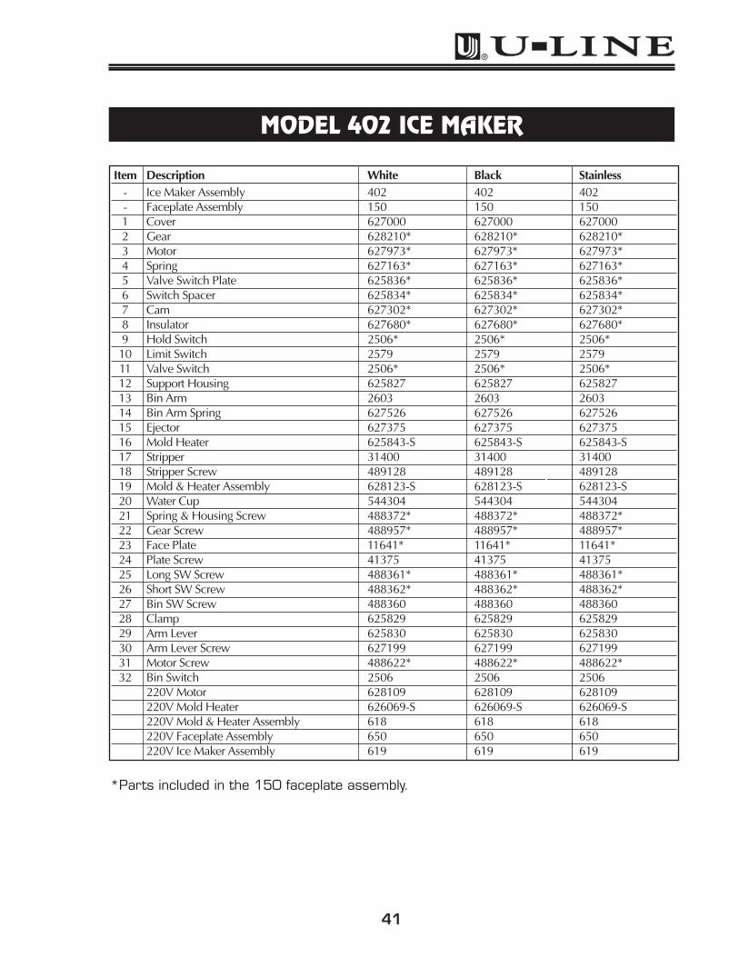
MODEL 402 ICE MAKER
402ICEMAKER
20
18
17
15
3219
16
14
2712
13
21
26
25 21
2930
10
11
7
9
4
5
28
8
2422
6
31
23
3
2
1
402ICEMAKER
Use only genuine U-Line replacement parts. U-Line ice maker parts are notthe same as standard FSP Whirlpool parts. Using non U-Line parts canreduce ice rate, cause water to overflow from ice maker mold, damage theunit, and may void the warranty.
41
*Parts included in the 150 faceplate assembly.
Item Description White Black Stainless- Ice Maker Assembly 402 402 402- Faceplate Assembly 150 150 1501 Cover 627000 627000 6270002 Gear 628210* 628210* 628210*3 Motor 627973* 627973* 627973*4 Spring 627163* 627163* 627163*5 Valve Switch Plate 625836* 625836* 625836*6 Switch Spacer 625834* 625834* 625834*7 Cam 627302* 627302* 627302*8 Insulator 627680* 627680* 627680*9 Hold Switch 2506* 2506* 2506*10 Limit Switch 2579 2579 257911 Valve Switch 2506* 2506* 2506*12 Support Housing 625827 625827 62582713 Bin Arm 2603 2603 260314 Bin Arm Spring 627526 627526 62752615 Ejector 627375 627375 62737516 Mold Heater 625843-S 625843-S 625843-S17 Stripper 31400 31400 3140018 Stripper Screw 489128De 489128Description 489128 Part No.19 Mold & Heater Assembly 628123-S 628123-S 628123-S20 Water Cup 544304 544304 54430421 Spring & Housing Screw 488372* 488372* 488372*22 Gear Screw 488957* 488957* 488957*23 Face Plate 11641* 11641* 11641*24 Plate Screw 41375 41375 4137525 Long SW Screw 488361* 488361* 488361*26 Short SW Screw 488362* 488362* 488362*27 Bin SW Screw 488360 488360 48836028 Clamp 625829 625829 62582929 Arm Lever 625830 625830 62583030 Arm Lever Screw 627199 627199 62719931 Motor Screw 488622* 488622* 488622*32 Bin Switch 2506 2506 2506
COMBO 75FF (1 of 2)Previous Design Starting With Serial Numbers
7CF300000, 7CF400000 or 7CF500000
For Item #10, see Model 402 Ice Maker (page 40) for separate breakdown.
Item Description Part No.
1 Handle 31489-4*2 Door Gasket 31493-4*3 Door Shelf Retainers (3) 31521-14 Shelf Retainer Rivet (6) 418245 Door Switch 19166 Door Ass’y 75-DOOR*7 Hinge, Top, 3 Hole 11697-ST*
Hinge, Top, 4 Hole 11849-ST*8 Pivot Screw, Top 41785-SS*9 Dr Switch Brkt 1171210 Ice Maker Ass’y 40211 Ice Bucket 3150112 Control 271713 Control Knob 4149214 Switch On-Off 205315 Lamp Bulb 3131716 Ice Bin Door 31523-S
Item Description Part No.
17 Glass Shelf (1) 31427-118 Glass Half Shelf (1) 3143519 Grille 11664*20 Glass Short Shelf (2) 31423-121 Trim Strip, Front Long (2) 31443-422 Trim Strip, Front Short (2) 31443-223 **Timer 2632-124 Fan Motor, Evaporator 5299-125 Fan Blade, Evaporator 3165626 Hinge, Bottom, 3 Hole 11697-SB*
Hinge, Bottom, 4 Hole 11849-SB*27 Pivot Screw, Bottom 41747-SS*28 Freezer Housing 11537-S29 Ice Bin Door Hinge 3146330 Evaporator & Heat Exchange 2631-S7531 Light Cover 3131432 Lamp Holder NLA
*Please indicate color.**Replaces P/N 2595 or 2632 through installation of kit.
1
11
2627
9
43
872
1923513
1214
617
1531
32
22
7
1821
20
28
2524
16
10
29
COMBO75FFa
43
COMBO 75FF (2 of 2)Previous Design Starting With Serial Numbers
7CF300000, 7CF400000 or 7CF500000
Item Description Part No.
1 Water Line 404FF2 Water Line Connection 418263 Plastic Nut & Sleeve Ass’y 412547 Cabinet Foot (4) 413198 Dryer 269210 Fan Motor, Condenser 526311 Fan Blade, Condenser 518812 Condenser 1951-FFS13 Back Panel 11769
* Replaces P/N 5402-FFS through installation of kit.** New part added through installation of kit.*** Replaces P/N's 5413 & 5414 through installation of kit.
PTC RELAY
RUNNING CAPACITOR
MS
C
188 24
12 21 7
16
10
112613
2
1
3
17
19
25
COMBO75FFb
Service and Parts Manual
44
COMBO 75FF (1 of 2)New Design Starting With Serial Numbers
7CF600000
For Item #10, see Model 402 Ice Maker (page 40) for separate breakdown.For Stainless Steel Models, see page 39 for handles and hinges.
Item Description Part No.
1 Handle 31489-4*2 Door Gasket 31493-4*3 Door Shelf Retainers (3) 31521-14 Shelf Retainer Rivet (6) 418245 Door Switch 19166 Door Ass’y 75-DOOR*7 Hinge, Top 11849-ST*8 Pivot Screw, Top 41785-SS*9 Dr Switch Brkt 1171210 Ice Maker Ass’y 40211 Ice Bucket 3150112 Control 271713 Control Knob 4149214 Switch On-Off 205315 Lamp Bulb 3131716 Ice Bin Door 31523-S
`Item Description Part No.
17 Glass Shelf (1) 31427-118 Glass Half Shelf (1) 3143519 Grille 11664*20 Glass Short Shelf (2) 31423-121 Trim Strip, Front Long (2) 31443-422 Trim Strip, Front Short (2) 31443-223 Timer 2632-2-S24 Fan Motor, Evaporator 5299-125 Fan Blade, Evaporator 3165626 Hinge, Bottom 11849-SB*27 Pivot Screw, Bottom 41747-SS*28 Freezer Housing 11537-S29 Ice Bin Door Hinge 3146330 Evaporator & Heat Exchanger 2631-57531 Light Cover 3131432 Lamp Holder NLA
*Please indicate color
9
1
11
2627
43
872
1923513
1214
617
22
7
18
21
20
28
2524
16
10
29
1531
32
COMBO75FFc
45
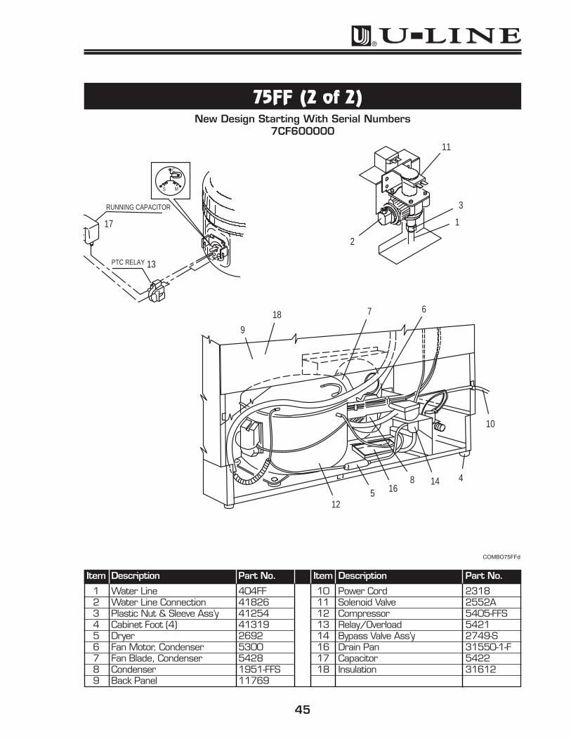
75FF (2 of 2)New Design Starting With Serial Numbers
7CF600000
Item Description Part No.
1 Water Line 404FF2 Water Line Connection 418263 Plastic Nut & Sleeve Ass’y 412544 Cabinet Foot (4) 413195 Dryer 26926 Fan Motor, Condenser 53007 Fan Blade, Condenser 54288 Condenser 1951-FFS9 Back Panel 11769
For Item #9, see Model 402 Ice Maker (page 40) for separate breakdown.
Item Description Part No.
1 Handle 31489-3*2 Door Gasket 31493-3*3 Door Shelf Retainer (Long) 31521-24 Door Shelf Retainer (Short) 31521-35 Fan Blade, Evaporator 316566 Pivot Hinge, Top 11697-ST*7 Pivot Hinge, Bottom 11695-S*9 Ice Maker Ass’y 40210 Ice Bucket 3150111 Complete Door Ass’y 29-DOOR*12 Control 271713 Grille 11663*14 Ice Bin Door 31523-S
Item Description Part No.
15 Glass Shelf (2) Short 31425-116 Switch On-Off 205317 Ice Bin Door Hinge (2) 3146318 Shelf Retainer Rivet (6) 4182419 Trim Strip, Front Short (2) 31443-120 Pivot Screw, Top 41785-SS*21 Condenser 1893-FFS22 **Timer 2632-123 Fan Motor, Evaporator 5299-124 Pivot Screw, Bottom 41747-SS*25 Freezer Housing 11471-S26 Control Knob 4149227 Evaporator & Heat Exchanger 2631-S29
*Please indicate color.**Replaces P/N 2595 or 2632 through installation of kit.
7
2
4
1626
15
19
9
17
206
24
1
18
14
52327
11
13
1221
25
310
COMBO29FFa
47
COMBO ULN-CO29FF (2 of 2)Serial Numbers
2CF300000, 2CF400000 or 2CF500000
Item Description Part No.
1 Water Line 404FF2 Water Line Connection 418263 Plastic Nut & Ass’y 4125412 Cabinet Foot (4) 4112513 Dryer 269215 Fan Motor, Condenser 526316 Fan Blade, Condenser 518818 Back Panel 11545-1
* Replaces P/N 5402-FFs through installation of kit.** New part added through installation of kit.*** Replaces P/N's 5413 and 5414 through installation of kit.
C
S M
PTC RELAY
RUNNING CAPACITOR
12
25
19
1328
16
30
24
18
1
3
20
2
15
22
29
COMBO29FFb
Service and Parts Manual
48
COMBO ULN-CO29FF (1 of 2)Serial Number 2CF600000
For Item #9, see Model 402 Ice Maker (page 40) for separate breakdown.
Item Description Part No.
1 Handle 31489-3*2 Door Gasket 31493-3*3 Door Shelf Retainer (Long) 31521-24 Door Shelf Retainer (Short) 31521-35 Fan Blade, Evaporator 316566 Pivot Hinge, Top 11697-ST*7 Pivot Hinge, Bottom 11695-S*9 Ice Maker Ass’y 40210 Ice Bucket 3150112 Complete Door Ass’y 29-DOOR*13 Control 271714 Grille 11663*15 Ice Bin Door 31523-S
Item Description Part No.
16 Glass Shelf (2) Short 31425-117 Switch On-Off 205318 Ice Bin Door Hinge (2) 3146319 Shelf Retainer Rivet (6) 4182420 Trim Strip, Front Short (2) 31443-121 Pivot Screw, Top 41785-SS*22 Condenser 1893-FFS23 Timer 2632-2-S24 Fan Motor, Evaporator 5299-125 Pivot Screw, Bottom 41747-SS*26 Freezer Housing 11471-S27 Control Knob 4149228 Evaporator & Heat Exchanger 2631-S29
*Please indicate color.
23
21
6
25
4
1
18
245
15
9
3
212
20
7
16
1322
10
26
141727
28 19
COMBO29FFc
49
COMBO ULN-CO29FF (2 of 2)Serial Number 2CF600000
Item Description Part No.
1 Water Line 404FF2 Water Line Connection 418263 Plastic Nut & Sleeve Ass’y 4125412 Cabinet Foot (4) 4112513 Dryer 269215 Fan Motor, Condenser 530016 Fan Blade, Condenser 542818 Back Panel 11545-1
( COMBO 75A MANUAL DEFROST HYBRID (1 OF 2)Serial Numbers
U-Combo 75A 2004 Design
14
12
15
13
16
8, 97 10, 11
6
5
4
3
1, 2 17
18
19
20
21, 22
23
CO75A_001
51
Item Description Black Stainless Steel1 Glass Shelf (Full) 40003 400032 Front Edge Trim 31443-9 31443-93 Ice Bucket 31687 316874 Bin Door Assembly 11957-S 11957-S5 Ice Maker Assembly 402-C75A 402-C75A6 Back Panel 11769 117697 Ice Bin Door Hinge 31463 314638 Lamp Cover 11859 118599 Lamp Bulb 31317 3131710 Glass Shelf (Narrow) 40002 4000211 Front Edge Trim 31443-8 31443-812 Top Hinge Assembly 11849-ST BLK 242-1-SS13 Top Pivot Screw 41785-SSB N/A14 Bottom Hinge Assembly 11849-SB BLK 245-1-SS15 Bottom Pivot Screw 41747-SSB N/A16 Door Assembly 75-DOORBLK 75-DOORSS17 Grille 11664 1166418 Control Knob 42067 4206719 Door Handle 31489-4-BLK 4201920 Door Gasket 31493-4-GRY 31493-4-GRY21 Door Shelf Retainer 31521-1 31521-122 Shelf Retainer Rivet 41824 4182423 Door Switch Actuator 11712 11712
COMBO 75A MANUAL DEFROST HYBRID (1 OF 2)
Service and Parts Manual
52
(COMBO 75A MANUAL DEFROST HYBRID (2 OF 2)Serial Numbers
U-Combo 75A 2004 Design
6
3
5
4
11
10
9
7
8
13
12
1415
1617
2
1
CO75A_002
53
Item Description Black Stainless Steel1 Fan Blade 5188 51882 Fan Motor 5263 52633 Water Line Connection 41826 418264 Water Line Assembly 404 4045 Plastic Nut & Sleeve Assembly 41254 412546 Water Valve 2552A 2552A7 Dryer 2694 26948 Evaporator & Heat Exchanger 74000-75/29 74000-75/299 Compressor Assembly 5402-S 5402-S10 Relay 5414 541411 Overload 5413 541312 Power Cord 2913 291313 Control 2781 278114 Light Switch 1916 191615 On / Off Switch 2053 205316 Condensor Assembly 1951-S 1951-S17 Cabinet Feet 41319 41319
COMBO 75A MANUAL DEFROST HYBRID (2 OF 2)
Service and Parts Manual
54
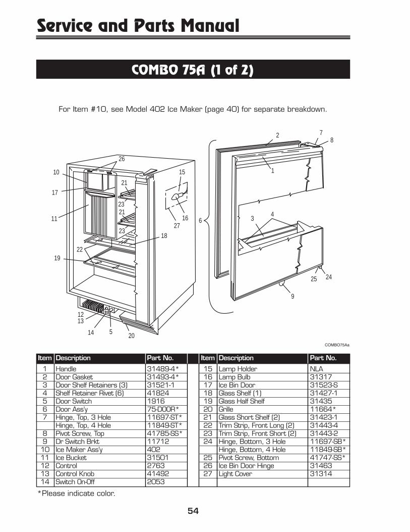
COMBO 75A (1 of 2)
For Item #10, see Model 402 Ice Maker (page 40) for separate breakdown.
Item Description Part No.
1 Handle 31489-4*2 Door Gasket 31493-4*3 Door Shelf Retainers (3) 31521-14 Shelf Retainer Rivet (6) 418245 Door Switch 19166 Door Ass’y 75-DOOR*7 Hinge, Top, 3 Hole 11697-ST*
Hinge, Top, 4 Hole 11849-ST*8 Pivot Screw, Top 41785-SS*9 Dr Switch Brkt 1171210 Ice Maker Ass’y 40211 Ice Bucket 3150112 Control 276313 Control Knob 4149214 Switch On-Off 2053
Item Description Part No.
15 Lamp Holder NLA16 Lamp Bulb 3131717 Ice Bin Door 31523-S18 Glass Shelf (1) 31427-119 Glass Half Shelf 3143520 Grille 11664*21 Glass Short Shelf (2) 31423-122 Trim Strip, Front Long (2) 31443-423 Trim Strip, Front Short (2) 31443-224 Hinge, Bottom, 3 Hole 11697-SB*
Hinge, Bottom, 4 Hole 11849-SB*25 Pivot Screw, Bottom 41747-SS*26 Ice Bin Door Hinge 3146327 Light Cover 31314
*Please indicate color.
COMBO75Aa
9
16 627
21
2123
15
23
1213
1
11
2425
43
872
20514
18
1922
17
10
26
COMBO75Aa
55
COMBO 75A (2 of 2)
Item Description Part No.
1 Water Line 4042 Water Line Connection 418263 Plastic Nut & Sleeve Ass’y 412544 Cabinet Feet (4) 413195 Dryer 26946 Evaporator & Heat Exchanger 2189-757 Fan Motor 52638 Fan Blade 5188
Item Description Part No.
9 Condenser 1951-S10 Back Panel 1176911 Power Cord 1855-112 Solenoid Valve 2552A13 Compressor 5402-S14 Relay 541415 Overload 5413
6
9
13
2
12
15
14
11
4
7
513
8
10
COMBO75Ab
*Please indicate color.
COMBO75Ab
Service and Parts Manual
56
COMBO 29A MANUAL DEFROST HYBRIDSerial Numbers
U-Combo 29A 2004 Design
2
3
4
5
6 7, 89
10
11
12
13
14
1516
18
17
19
30
27
29
28
36
35
26
25
31
3233
24
2021
2223
34
1
CO29ACO29A
57
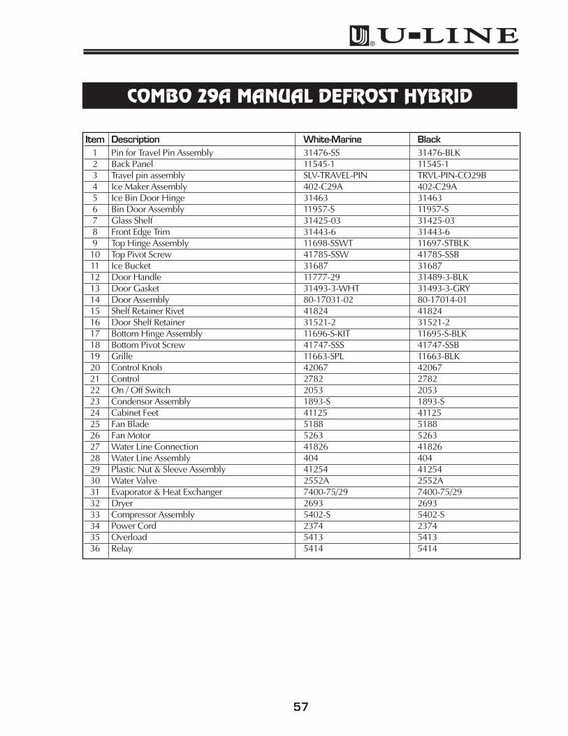
Item Description White-Marine Black1 Pin for Travel Pin Assembly 31476-SS 31476-BLK2 Back Panel 11545-1 11545-13 Travel pin assembly SLV-TRAVEL-PIN TRVL-PIN-CO29B4 Ice Maker Assembly 402-C29A 402-C29A5 Ice Bin Door Hinge 31463 314636 Bin Door Assembly 11957-S 11957-S7 Glass Shelf 31425-03 31425-038 Front Edge Trim 31443-6 31443-69 Top Hinge Assembly 11698-SSWT 11697-STBLK10 Top Pivot Screw 41785-SSW 41785-SSB11 Ice Bucket 31687 3168712 Door Handle 11777-29 31489-3-BLK13 Door Gasket 31493-3-WHT 31493-3-GRY14 Door Assembly 80-17031-02 80-17014-0115 Shelf Retainer Rivet 41824 4182416 Door Shelf Retainer 31521-2 31521-217 Bottom Hinge Assembly 11696-S-KIT 11695-S-BLK18 Bottom Pivot Screw 41747-SSS 41747-SSB19 Grille 11663-SPL 11663-BLK20 Control Knob 42067 4206721 Control 2782 278222 On / Off Switch 2053 205323 Condensor Assembly 1893-S 1893-S24 Cabinet Feet 41125 4112525 Fan Blade 5188 518826 Fan Motor 5263 526327 Water Line Connection 41826 4182628 Water Line Assembly 404 40429 Plastic Nut & Sleeve Assembly 41254 4125430 Water Valve 2552A 2552A31 Evaporator & Heat Exchanger 7400-75/29 7400-75/2932 Dryer 2693 269333 Compressor Assembly 5402-S 5402-S34 Power Cord 2374 237435 Overload 5413 541336 Relay 5414 5414
COMBO 29A MANUAL DEFROST HYBRID
Service and Parts Manual
58
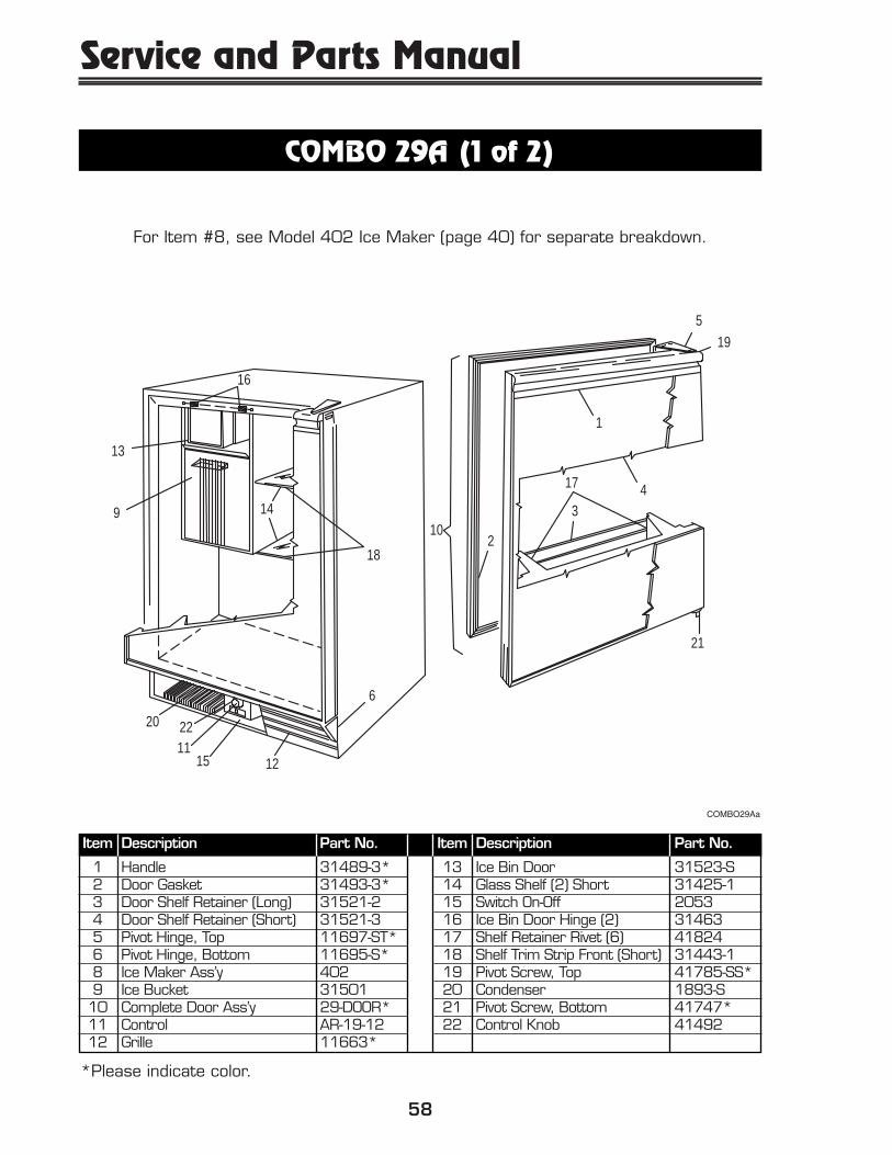
COMBO 29A (1 of 2)
For Item #8, see Model 402 Ice Maker (page 40) for separate breakdown.
Item Description Part No.
1 Handle 31489-3*2 Door Gasket 31493-3*3 Door Shelf Retainer (Long) 31521-24 Door Shelf Retainer (Short) 31521-35 Pivot Hinge, Top 11697-ST*6 Pivot Hinge, Bottom 11695-S*8 Ice Maker Ass’y 4029 Ice Bucket 3150110 Complete Door Ass’y 29-DOOR*11 Control AR-19-1212 Grille 11663*
Item Description Part No.
13 Ice Bin Door 31523-S14 Glass Shelf (2) Short 31425-115 Switch On-Off 205316 Ice Bin Door Hinge (2) 3146317 Shelf Retainer Rivet (6) 4182418 Shelf Trim Strip Front (Short) 31443-119 Pivot Screw, Top 41785-SS*20 Condenser 1893-S21 Pivot Screw, Bottom 41747*22 Control Knob 41492
*Please indicate color.
19
5
21
4
1
16
13
3
210
18
6
14
2220
9
121511
17
COMBO29Aa
COMBO29Aa
59
COMBO 29A (2 of 2)
Item Description Part No.
1 Water Line 4042 Water Line Connection 418263 Plastic Nut & Sleeve Ass’y 412544 Cabinet Foot (4) 411255 Dryer 26946 Evaporator & Heat Exchanger 2189-297 Fan Motor 5263
Item Description Part No.
8 Fan Blade 51889 Back Panel 11545-110 Power Cord 1855-111 Solenoid Valve 2552A12 Relay 541413 Compressor 5402-S14 Overload 5413
DETAIL "A"
SEE DETAIL "A"
13
11
2
14
12 4
9
8
7
13
56
10
COMBO29Ab
Service and Parts Manual
60
MODEL 95 (1 of 2)
For Item #9, see Model 402 Ice Maker (page 40) for separate breakdown.
Hinge, Bottom, 4 Hole 245-1*15 Door Gasket 31493-4*
Item Description Part No.
16 Door Handle 41984-3*17 Compressor 5400-S18 Glass Half Shelf (1) 3143519 Door Ass’y 75WC-DOOR*20 Light On-Off Switch 205321 Lamp Holder NLA22 Overload 541123 Back Panel 1176924 Light Cover 3131425 Dryer 269426 Fan Motor 526327 Fan Blade 518828 Power Cord 231529 Evaporator & Heat Exchanger 2186-S30 Leveler Feet (4) 4131931 Lock Ass’y 41734-S32 Relay 5412
19
3029
2511
26
27281723
14
3116
13
15
10
12
256
720
4
18
39
24821
22
32
1
*Please indicate color.
MODEL75WC
Service and Parts Manual
70
MODEL 75F
Item Description Part No.
2 Grille 11664*3 Glass Shelves (2) 31427-14 Condenser 1951-S5 Control 25806 Control Knob-Silver 417157 Glass Half Shelf (1) 314358 Pivot Screw, Top 41785-SS*9 Hinge, Top 11697-ST*
Hinge, Top, 4 Hole 11849-ST*10 Door Gasket 31493-4*11 Door Handle 31489-4*12 Door Shelf Retainers (3) 31521-113 Compressor 5402-S14 Shelf Retainer Rivet (6) 41824
Item Description Part No.
15 Door Ass’y 75-DOOR*16 Overload 541317 Pivot Screw, Bottom 41747-SS*18 Back Panel 1176919 Dryer 269420 Fan Motor 526321 Fan Blade 518822 Power Cord 223423 Leveler Feet (4) 4131924 Trim Strip (4) 31443-425 Evaporator 2187-FS26 Hinge, Bottom 11697-SB*
Hinge, Bottom, 4 Hole 11849-SB*27 Relay 5414
16
2723
19
222120413
18
10
7
24
3
25
1726
98
11
12
14
25
6
4
15
*Please indicate color.
MODEL75F
71
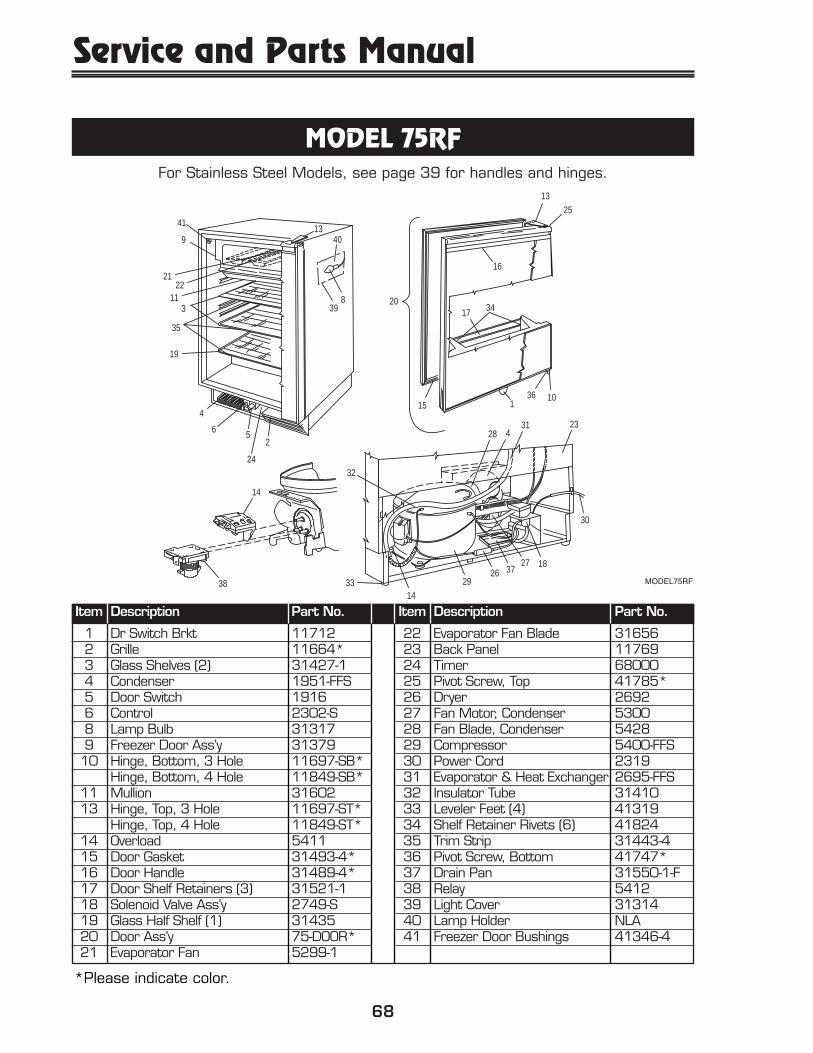
MODEL 75RFor Stainless Steel Models, see page 39 for handles and hinges.
Item Description Part No.
1 Dr Switch Brkt 117122 Grille 11664*3 Glass Shelves (2) 31427-14 Condenser 1951-S5 Door Switch 19166 Control 2923-S8 Lamp Bulb 313179 Glass Half Shelf (1) 3143510 Drain Cup 1150811 Drain Pan 31550-1-F12 Drain Trough 31391-113 Hinge, Top, 3 Hole 11697-ST*
Hinge, Top, 4 Hole 11849-ST*14 Pivot Screw, Top 41785-SS*15 Door Gasket 31493-4*16 Door Handle 31489-4*17 Door Shelf Retainers (3) 31521-118 Compressor 5400-S
Item Description Part No.
19 Shelf Retainer Rivets (6) 4182420 Door Ass’y 75-DOOR*22 Overload 541123 Back Panel 1176924 Trim Strips, Front Long (3) 31443-425 Trim Strips, Rear Long (2) 31444-426 Dryer 269427 Fan Motor 526328 Fan Blade 518830 Power Cord 230631 Evaporator & Heat Exchanger 2333-S33 Leveler Feet (4) 4131934 Hinge, Bottom, 3 Hole 11697-SB*
Hinge, Top, 4 Hole 11849-ST*15 Door Gasket 31493-4*16 Door Handle 31489-4*17 Door Shelf Retainers (3) 31521-118 Solenoid Valve Ass’y 2749-S19 Glass Half Shelf (1) 3143520 Door Ass’y 75-DOOR*
Item Description Part No.
22 Overload 541123 Back Panel 1176924 Timer 2632-125 Pivot Screw, Top 41785*26 Dryer (75AD) 269227 Fan Motor 526328 Fan Blade 518829 Compressor 5400-FFS30 Power Cord 224331 Evaporator & Heat Exchanger 2188-FFS32 Insulator Tube 3141033 Leveler Feet (4) 4131934 Shelf Retainer Rivets (6) 4182435 Trim Strip 31443-436 Pivot Screw, Bottom 41747*37 Drain Pan 31550-1-F38 Relay 541239 Light Cover 3131440 Light Holder NLA41 Freezer Door Bushings 41346-4
31
33
234
151036
2513
224
5
764
19
35
311
913
30
26 3729
27 18
28
32
22
38
16
8
17 34
1
20
40
39
41
*Please indicate color.
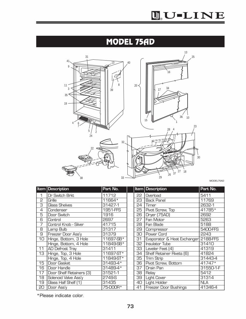
MODEL75AD
Service and Parts Manual
74
MODEL 29AD
Item Description Part No.
2 Grille 11663*3 Glass Shelves (3) 31426-14 Condenser 1893-S5 Control 26966 Control Knob 417157 Shelf Retainer Rivets (6) 418248 Auto Timer 26849 Drain Pan 31550-1-F10 Drip Tray 31360-F11 Door Gasket 31493-3*12 Door Handle 31489-3*13 Door Shelf Retainers (Long) (2) 31521-214 Door Hinge, Upper 11697-ST*15 Door Shelf Retainer (Short) (1) 31521-316 Compressor 5400-S17 Relay 5412
Item Description Part No.
18 Door Ass’y 29-DOOR*19 Back Panel 11545-120 Dryer 269321 Fan Motor 526322 Fan Blade 518823 Power Cord 231424 Evaporator & Heat Exchanger 2018-S25 Cabinet Feet (4) 4112526 Drain Tube 41615-127 Evaporator Door 31659-S28 Shelf Trim Strip Front (Long) (3) 31443-329 Hinge Support, Bottom 11695-S*30 Pivot Screw, Top 41785*31 Overload 541132 Pivot Screw, Bottom 41747*
32
9
26
22
1948
11
18
29
26
54
3
2628
1024
27
21
2025
16
24
23
1430
12
713-15
31
17
*Please indicate color.
MODEL29AD
75
MODEL 29R
Item Description Part No.
2 Grille 11663*3 Glass Shelves (3) 31426-14 Condenser 1893-S5 Control 2766-S7 Door Shelf Retainer (Short) (1) 31521-38 Drain Cup 115089 Drain Pan 31550-1-F10 Drain Trough 3139111 Door Gasket 31493-3*12 Door Handle 31489-3*13 Door Shelf Retainers (Long) (2) 31521-214 Door Hinge, Upper 11697-ST*15 Door Hinge, Lower 11695-S*16 Compressor 5400-S17 Relay 5412
Item Description Part No.
17 Relay 541218 Door Ass’y 29-DOOR*19 Back Panel 11545-120 Dryer 269321 Fan Motor 526322 Fan Blade 518823 Power Cord 223424 Evaporator & Heat Exchanger 1960-S25 Cabinet Feet (4) 4112526 Shelf Retainer Rivet (6) 4182427 Shelf Trim Strip (Long) Front (3) 31443-328 Shelf Trim Strip (Long) Rear (3) 31444-329 Pivot Screw, Top 41785*30 Overload 541131 Pivot Screw, Bottom 41747*
23
9 20 25
21
2216
19
13 (7)
2626
12
8
10
24
28
3
27
18
1429
11
25
4
30
17
31
15
*Please indicate color.
MODEL29R
Service and Parts Manual
76
MODEL 29WC
Item Description Part No.
1 Dr Switch Brkt 117122 Grille 11663*3 Condenser 1893-S4 Control 2767-S6 Drain Cup 115087 Drain Pan 31550-1-F8 Drain Trough 313919 Door Gasket 31493-3*10 Door Handle 41984-2-BLK11 Wire Wine Rack 229913 Light Bulb 3131714 Light Socket NLA15 Door Hinge, Upper 1848A-S*16 Hinge Plate, Lower Right 1847-2-S*17 Compressor 5400-S18 Relay 5412
Item Description Part No.
18 Relay 541219 Door Ass’y WC29-DOOR20 Back Panel 11545-121 Dryer 269422 Fan Motor 526323 Fan Blade 518824 Power Cord 231525 Evaporator & Heat Exchanger 1960-S26 Cabinet Feet (4) 4112527 Light Door Switch 191628 Light On-Off Switch 205329 Light Cover 3131431 Lower Hinge Support 11624-1-S*32 Lock Ass’y 41734-S33 Hinge Plate, Top Right 1847-1-S*34 Overload 5411
33
25
3312274
283
6
8
11
29
1314
20
23
22
2621
17
7
24
34
18
19
161
3210
15
9
*Please indicate color.
MODEL29WC
77
MODEL 15RFor Stainless Steel Models, see page 39 for handles and hinges.
Item Description Part No.
1 Dr Switch Brkt 117122 Grille 31543*3 Back Panel 418024 Feet Leveler (4) 413195 Door Shelf Retainers (3) 31521-36 Glass Shelf (3) 117717 Glass Shelf (1) 117708 Drain Cup 115089 Drain Pan 31550-1-F10 Drain Trough 31391-211 Hinge Bracket, Top 11697-ST*12 Hinge Bracket, Bottom 11695-S*13 Hinge Pin, Top 41785-SS*14 Hinge Pin, Bottom 41747-SS*15 Door Ass’y 15R-DOOR*16 Door Handle 31489-2*17 Door Gasket 31493-6*
Item Description Part No.
18 Shelf Retainer Rivet (6) 4182420 Control 2766-S21 Door Switch (Plunger) 191622 Lamp Cover 3131423 Lamp Holder NLA24 Lamp Bulb 3131725 Compressor 5400-S26 Condenser 2223-S27 Relay 541228 Evaporator & Heat Exchanger 2878-01-S29 Dryer 269430 Fan Motor, Condenser 526331 Fan Blade, Condenser 518832 Power Cord 230733 Glass Trim Strip, Front (4) 31443-534 Glass Trim Strip, Rear (3) 31444-535 Overload 5411
1
175
18
131116
15
331
2825
293094
32
35
27
25
2026
21
2
7
8
10
33
6
34
3
22, 23, 24
14
12
*Please indicate color.
MODEL15R
Service and Parts Manual
78
MODEL 15WCFor Stainless Steel Models, see page 39 for handles and hinges.
Item Description Part No.
1 Dr Switch Brkt 117122 Grille 31543*3 Back Panel 418024 Feet Leveler (4) 413195 Wine Rack 23016 Wine Rack Clip 316487 Glass Half Shelf (1) 117708 Drain Cup 115089 Drain Pan 31550-1-F10 Drain Trough 31391-211 Hinge Bracket Ass’y, Top 1848A-S*12 Hinge Bracket, Bottom 11624-1-S*13 Pivot Hinge, Top 1847-1-S*14 Pivot Hinge, Bottom 1847-2-S*15 Door Ass’y 15WC-DOOR*16 Door Handle 41984-1*17 Door Gasket 31493-6
Item Description Part No.
18 Lock Ass’y 41734-S20 Control 2767-S21 Door Switch - Plunger 191622 Lamp On-Off Switch 205323 Lamp Cover 3131424 Lamp Holder NLA25 Lamp Bulb 3131726 Compressor 5400-S27 Condenser 2223-S28 Relay 541229 Evaporator & Heat Exchanger 2649-S30 Dryer 269431 Fan Motor, Condenser 526332 Fan Blade, Condenser 518833 Power Cord 231534 Glass Trim Strip Front 31443-535 Overload 5411
1
22
12
18
28
34
7
8
10
5
6
1311
14
3
29
15
17
3
1623, 24, 25
3226
33
3026
94 31
35
27
21
2
20
�
*Please indicate color.
MODEL15WC
79
How to Order Replacement Parts
1. Locate the illustration(s) for the model you are servicing.
2. Refer to the area where the desired part would be installed, locate the part and notethe item number assigned to it.
3. Locate the item number in the left column of the parts listing which is on the nextpage from the product illustration. Note the full description and the correspondingpart number. If this is for a warranty unit, please indicate and record the model andserial numbers.
4. When ordering parts, it will be necessary to supply us with Model Number, SerialNumber, Part Number, Part Description and in some cases Color or Voltage.
5. U-Line requires the return of the parts listed below if replaced under warranty.
• Fan motors (condenser and evaporator)• Temperature controls• Water solenoid valves• Pumps• Control boards
• Ice maker motors• Bypass solenoids• Compressors (two years old or less -
lines soldered closed)
All warranty parts will be shipped at no charge as long as warranty status has been confirmed. We require that some parts be returned to us, so we may return them toour vendor. It will be noted on your packing list if we require you to return a part or if youmay field scrap it. If U-Line requires a defective part to be returned, a prepaid shippinglabel will be included with your new replacement part. When returning parts pleaseenclose a copy of your packing list and a copy of your labor claim, showing the model andserial number, and tag or label the part with the nature of the defect.
Our warranty records may not match the customer’s information. In this case a proof ofpurchase will be required. If you do not have the proof of purchase at the time the orderis placed, the part will be sent net 15 days (COD if you don’t have an open account withU-Line Corporation). When the proof of purchase is provided we will credit your account(a check will be sent if the part was sent COD).
6. Parts may be ordered by FAX, phone or on-line:
FAX Number (414) 354-7905Phone Number (414) 354-0300 or (414) 354-7885; press 3www.U-LineService.com
To expedite parts shipments, FAX all parts orders to: (414) 354-7905. Copy the FAXParts Order Form, located in the back of this manual, when placing an order.
7. Effective immediately, U-Line will not pay warranty claims for the replacement of acomplete ice maker assembly. Complete ice maker assembly replacement is not necessary because all ice maker parts are available as replacement parts and arestocked in our inventory.
REPLACEMENT PARTS: Use only genuine U-Line replacement parts. The use of non-U-Line parts can reduce ice rate, cause water to overflow from ice maker mold,damage the unit, and may void the warranty.
PARTS LISTING
80
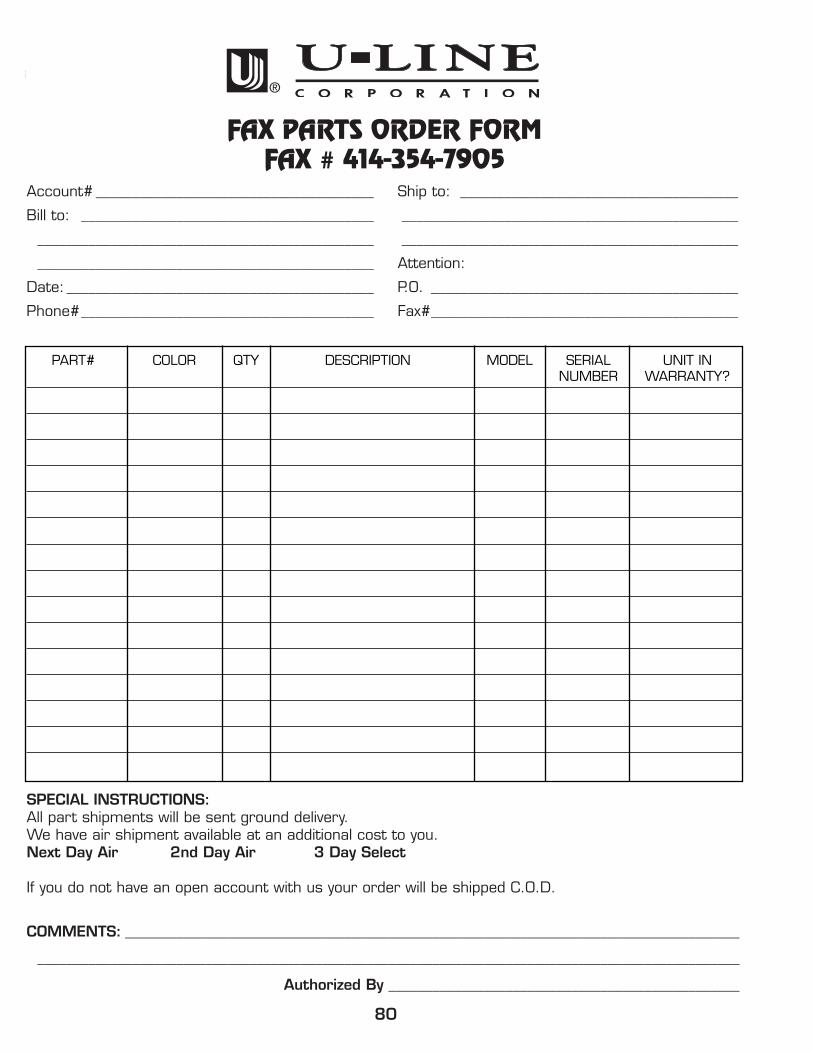
FAX PARTS ORDER FORMFAX # 414-354-7905
Account# ______________________________________ Ship to: ______________________________________
Bill to: ________________________________________ ______________________________________________
PART# COLOR QTY DESCRIPTION MODEL SERIAL UNIT INNUMBER WARRANTY?
SPECIAL INSTRUCTIONS:All part shipments will be sent ground delivery.We have air shipment available at an additional cost to you.Next Day Air 2nd Day Air 3 Day Select
If you do not have an open account with us your order will be shipped C.O.D.