174
Service and Maintenance Manual Model E300A E300AJ E300AJP P/N - 3120772 January 23, 2009

Service and Maintenance Manual
ModelE300AE300AJ
E300AJP
P/N - 3120772
January 23, 2009


INTRODUCTION
SECTION A. INTRODUCTION - MAINTENANCE SAFETY PRECAUTIONS
A GENERALThis section contains the general safety precautionswhich must be observed during maintenance of the aerialplatform. It is of utmost importance that maintenance per-sonnel pay strict attention to these warnings and precau-tions to avoid possible injury to themselves or others, ordamage to the equipment. A maintenance program mustbe followed to ensure that the machine is safe to operate.
MODIFICATION OF THE MACHINE WITHOUT CERTIFICATION BY ARESPONSIBLE AUTHORITY THAT THE MACHINE IS AT LEAST ASSAFE AS ORIGINALLY MANUFACTURED, IS A SAFETY VIOLATION.
The specific precautions to be observed during mainte-nance are inserted at the appropriate point in the manual.These precautions are, for the most part, those that applywhen servicing hydraulic and larger machine componentparts.
Your safety, and that of others, is the first considerationwhen engaging in the maintenance of equipment. Alwaysbe conscious of weight. Never attempt to move heavyparts without the aid of a mechanical device. Do not allowheavy objects to rest in an unstable position. When raisinga portion of the equipment, ensure that adequate supportis provided.
SINCE THE MACHINE MANUFACTURER HAS NO DIRECT CON-TROL OVER THE FIELD INSPECTION AND MAINTENANCE, SAFETYIN THIS AREA RESPONSIBILITY OF THE OWNER/OPERATOR.
B HYDRAULIC SYSTEM SAFETYIt should be noted that the machines hydraulic systemsoperate at extremely high potentially dangerous pres-sures. Every effort should be made to relieve any systempressure prior to disconnecting or removing any portion ofthe system.
Relieve system pressure by cycling the applicable controlseveral times with the engine stopped and ignition on, todirect any line pressure back into the reservoir. Pressurefeed lines to system components can then be discon-nected with minimal fluid loss.
C MAINTENANCE
FAILURE TO COMPLY WITH SAFETY PRECAUTIONS LISTED INTHIS SECTION MAY RESULT IN MACHINE DAMAGE, PERSONNELINJURY OR DEATH AND IS A SAFETY VIOLATION.
• ENSURE REPLACEMENT PARTS OR COMPONENTSARE IDENTICAL OR EQUIVALENT TO ORIGINAL PARTSOR COMPONENTS.
• NO SMOKING IS MANDATORY. NEVER REFUEL DUR-ING ELECTRICAL STORMS. ENSURE THAT FUEL CAPIS CLOSED AND SECURE AT ALL OTHER TIMES.
• REMOVE ALL RINGS, WATCHES AND JEWELRY WHENPERFORMING ANY MAINTENANCE.
• DO NOT WEAR LONG HAIR UNRESTRAINED, ORLOOSE-FITTING CLOTHING AND NECKTIES WHICHARE APT TO BECOME CAUGHT ON OR ENTANGLEDIN EQUIPMENT.
• OBSERVE AND OBEY ALL WARNINGS AND CAUTIONSON MACHINE AND IN SERVICEMANUAL.
• KEEP OIL, GREASE, WATER, ETC. WIPED FROMSTANDING SURFACES AND HAND HOLDS.
• USE CAUTION WHEN CHECKING A HOT, PRESSUR-IZED COOLANT SYSTEM.
• NEVER WORK UNDER AN ELEVATED BOOM UNTILBOOM HAS BEEN SAFELY RESTRAINED FROM ANYMOVEMENT BY BLOCKING OR OVERHEAD SLING, ORBOOM SAFETY PROP HAS BEEN ENGAGED.
• BEFORE MAKING ADJUSTMENTS, LUBRICATING ORPERFORMING ANY OTHER MAINTENANCE, SHUTOFF ALL POWER CONTROLS.
• BATTERY SHOULD ALWAYS BE DISCONNECTEDDUR-ING REPLACEMENT OF ELECTRICAL COMPONENTS.
• KEEP ALL SUPPORT EQUIPMENT AND ATTACH-MENTS STOWED IN THEIR PROPER PLACE.
• USE ONLY APPROVED, NONFLAMMABLE CLEANINGSOLVENTS.
3120772 – JLG Lift – A-1

INTRODUCTION
REVISON LOG
Original Issue November 15, 2000Revised October 1, 2001Revised April 10, 2002Revised June 4, 2002Revised November 3, 2006Revised January 14, 2008Revised January 23, 2009
A-2 – JLG Lift – 3120772

3120772 – JLG Lift – i
TABLE OF CONTENTS
SECTION NO. TITLE PAGE NO.
SECTION A - INTRODUCTION - MAINTENANCE SAFETY PRECAUTIONS
A General . . . . . . . . . . . . . . . . . . . . . . . . . . . . . . . . . . . . . . . . . . . . . . . . . . . . . . . . . . . . . . . . . . . . . .A-1B Hydraulic System Safety . . . . . . . . . . . . . . . . . . . . . . . . . . . . . . . . . . . . . . . . . . . . . . . . . . . . . . . . .A-1C Maintenance . . . . . . . . . . . . . . . . . . . . . . . . . . . . . . . . . . . . . . . . . . . . . . . . . . . . . . . . . . . . . . . . . .A-1
SECTION 1 - SPECIFICATIONS
1.1 Capacities . . . . . . . . . . . . . . . . . . . . . . . . . . . . . . . . . . . . . . . . . . . . . . . . . . . . . . . . . . . . . . . . . . . .1-11.2 Operating specifications . . . . . . . . . . . . . . . . . . . . . . . . . . . . . . . . . . . . . . . . . . . . . . . . . . . . . . . . .1-11.3 Battery Charger . . . . . . . . . . . . . . . . . . . . . . . . . . . . . . . . . . . . . . . . . . . . . . . . . . . . . . . . . . . . . . . .1-21.4 Drive System . . . . . . . . . . . . . . . . . . . . . . . . . . . . . . . . . . . . . . . . . . . . . . . . . . . . . . . . . . . . . . . . . .1-21.5 Tires . . . . . . . . . . . . . . . . . . . . . . . . . . . . . . . . . . . . . . . . . . . . . . . . . . . . . . . . . . . . . . . . . . . . . . . . .1-21.6 Hydraulic Filter. . . . . . . . . . . . . . . . . . . . . . . . . . . . . . . . . . . . . . . . . . . . . . . . . . . . . . . . . . . . . . . . .1-21.7 Hydraulic Pump/Electric Motor Assembly . . . . . . . . . . . . . . . . . . . . . . . . . . . . . . . . . . . . . . . . . . .1-21.8 Dimensional Data . . . . . . . . . . . . . . . . . . . . . . . . . . . . . . . . . . . . . . . . . . . . . . . . . . . . . . . . . . . . . .1-21.9 Function Speeds . . . . . . . . . . . . . . . . . . . . . . . . . . . . . . . . . . . . . . . . . . . . . . . . . . . . . . . . . . . . . . .1-31.10 Torque Specifications . . . . . . . . . . . . . . . . . . . . . . . . . . . . . . . . . . . . . . . . . . . . . . . . . . . . . . . . . . .1-31.11 Pressure Settings . . . . . . . . . . . . . . . . . . . . . . . . . . . . . . . . . . . . . . . . . . . . . . . . . . . . . . . . . . . . . .1-31.12 Cylinder Specifications . . . . . . . . . . . . . . . . . . . . . . . . . . . . . . . . . . . . . . . . . . . . . . . . . . . . . . . . . .1-41.13 Major Component Weights . . . . . . . . . . . . . . . . . . . . . . . . . . . . . . . . . . . . . . . . . . . . . . . . . . . . . . .1-4
Critical Stability Weights . . . . . . . . . . . . . . . . . . . . . . . . . . . . . . . . . . . . . . . . . . . . . . . . . . . . 1-51.14 Serial Number Locations. . . . . . . . . . . . . . . . . . . . . . . . . . . . . . . . . . . . . . . . . . . . . . . . . . . . . . . . .1-51.15 Hydraulic Oil . . . . . . . . . . . . . . . . . . . . . . . . . . . . . . . . . . . . . . . . . . . . . . . . . . . . . . . . . . . . . . . . . .1-51.16 Lubrication. . . . . . . . . . . . . . . . . . . . . . . . . . . . . . . . . . . . . . . . . . . . . . . . . . . . . . . . . . . . . . . . . . . .1-7
SECTION 2 - GENERAL
2.1 Machine Preparation, Inspection, and Maintenance . . . . . . . . . . . . . . . . . . . . . . . . . . . . . . . . . . .2-1General. . . . . . . . . . . . . . . . . . . . . . . . . . . . . . . . . . . . . . . . . . . . . . . . . . . . . . . . . . . . . . . . . . 2-1Preparation, Inspection, and Maintenance . . . . . . . . . . . . . . . . . . . . . . . . . . . . . . . . . . . . . . 2-1Pre-Start Inspection . . . . . . . . . . . . . . . . . . . . . . . . . . . . . . . . . . . . . . . . . . . . . . . . . . . . . . . . 2-1Pre-Delivery Inspection and Frequent Inspection . . . . . . . . . . . . . . . . . . . . . . . . . . . . . . . . . 2-1Annual Machine Inspection . . . . . . . . . . . . . . . . . . . . . . . . . . . . . . . . . . . . . . . . . . . . . . . . . . 2-1Preventative Maintenance . . . . . . . . . . . . . . . . . . . . . . . . . . . . . . . . . . . . . . . . . . . . . . . . . . . 2-1
2.2 Service and Guidelines . . . . . . . . . . . . . . . . . . . . . . . . . . . . . . . . . . . . . . . . . . . . . . . . . . . . . . . . . .2-2General. . . . . . . . . . . . . . . . . . . . . . . . . . . . . . . . . . . . . . . . . . . . . . . . . . . . . . . . . . . . . . . . . . 2-2Safety and Workmanship . . . . . . . . . . . . . . . . . . . . . . . . . . . . . . . . . . . . . . . . . . . . . . . . . . . 2-2Cleanliness. . . . . . . . . . . . . . . . . . . . . . . . . . . . . . . . . . . . . . . . . . . . . . . . . . . . . . . . . . . . . . . 2-2Components Removal and Installation . . . . . . . . . . . . . . . . . . . . . . . . . . . . . . . . . . . . . . . . . 2-2Component Disassembly and Reassembly . . . . . . . . . . . . . . . . . . . . . . . . . . . . . . . . . . . . . 2-3Pressure-Fit Parts. . . . . . . . . . . . . . . . . . . . . . . . . . . . . . . . . . . . . . . . . . . . . . . . . . . . . . . . . . 2-3Bearings. . . . . . . . . . . . . . . . . . . . . . . . . . . . . . . . . . . . . . . . . . . . . . . . . . . . . . . . . . . . . . . . . 2-3Gaskets . . . . . . . . . . . . . . . . . . . . . . . . . . . . . . . . . . . . . . . . . . . . . . . . . . . . . . . . . . . . . . . . . 2-3Bolt Usage and Torque Application . . . . . . . . . . . . . . . . . . . . . . . . . . . . . . . . . . . . . . . . . . . 2-3Hydraulic Lines and Electrical Wiring . . . . . . . . . . . . . . . . . . . . . . . . . . . . . . . . . . . . . . . . . . 2-3Hydraulic System. . . . . . . . . . . . . . . . . . . . . . . . . . . . . . . . . . . . . . . . . . . . . . . . . . . . . . . . . . 2-3Lubrication . . . . . . . . . . . . . . . . . . . . . . . . . . . . . . . . . . . . . . . . . . . . . . . . . . . . . . . . . . . . . . . 2-3Battery . . . . . . . . . . . . . . . . . . . . . . . . . . . . . . . . . . . . . . . . . . . . . . . . . . . . . . . . . . . . . . . . . . 2-3Lubrication and Servicing . . . . . . . . . . . . . . . . . . . . . . . . . . . . . . . . . . . . . . . . . . . . . . . . . . . 2-3
2.3 Lubrication and Information . . . . . . . . . . . . . . . . . . . . . . . . . . . . . . . . . . . . . . . . . . . . . . . . . . . . . .2-4Hydraulic System. . . . . . . . . . . . . . . . . . . . . . . . . . . . . . . . . . . . . . . . . . . . . . . . . . . . . . . . . . 2-4Hydraulic Oil . . . . . . . . . . . . . . . . . . . . . . . . . . . . . . . . . . . . . . . . . . . . . . . . . . . . . . . . . . . . . 2-4Changing Hydraulic Oil . . . . . . . . . . . . . . . . . . . . . . . . . . . . . . . . . . . . . . . . . . . . . . . . . . . . . 2-4Lubrication Specifications . . . . . . . . . . . . . . . . . . . . . . . . . . . . . . . . . . . . . . . . . . . . . . . . . . . 2-4
2.4 Cylinder Drift Test . . . . . . . . . . . . . . . . . . . . . . . . . . . . . . . . . . . . . . . . . . . . . . . . . . . . . . . . . . . . . .2-5Platform Drift . . . . . . . . . . . . . . . . . . . . . . . . . . . . . . . . . . . . . . . . . . . . . . . . . . . . . . . . . . . . . 2-5Cylinder Drift . . . . . . . . . . . . . . . . . . . . . . . . . . . . . . . . . . . . . . . . . . . . . . . . . . . . . . . . . . . . . 2-5
2.5 Pins and Composite Bearing Repair Guidelines . . . . . . . . . . . . . . . . . . . . . . . . . . . . . . . . . . . . . .2-52.6 Welding on JLG Equipment . . . . . . . . . . . . . . . . . . . . . . . . . . . . . . . . . . . . . . . . . . . . . . . . . . . . . .2-6

ii – JLG Lift – 3120772
TABLE OF CONTENTS
SECTION NO. TITLE PAGE NO.Do the Following When Welding on JLG Equipment . . . . . . . . . . . . . . . . . . . . . . . . . . . . . . 2-6Do NOT Do the Following When Welding on JLG Equipment . . . . . . . . . . . . . . . . . . . . . . . 2-6
SECTION 3 - CHASSIS & TURNTABLE
3.1 Tires and Wheels. . . . . . . . . . . . . . . . . . . . . . . . . . . . . . . . . . . . . . . . . . . . . . . . . . . . . . . . . . . . . . .3-1Tire Wear and Damage . . . . . . . . . . . . . . . . . . . . . . . . . . . . . . . . . . . . . . . . . . . . . . . . . . . . . 3-1Wheel and Tire Replacement . . . . . . . . . . . . . . . . . . . . . . . . . . . . . . . . . . . . . . . . . . . . . . . . 3-1Wheel Installation. . . . . . . . . . . . . . . . . . . . . . . . . . . . . . . . . . . . . . . . . . . . . . . . . . . . . . . . . . 3-1
3.2 Drive Hub Part No. 2780236 . . . . . . . . . . . . . . . . . . . . . . . . . . . . . . . . . . . . . . . . . . . . . . . . . . . . . .3-2Disassembly. . . . . . . . . . . . . . . . . . . . . . . . . . . . . . . . . . . . . . . . . . . . . . . . . . . . . . . . . . . . . . 3-2Disassembly of Cover . . . . . . . . . . . . . . . . . . . . . . . . . . . . . . . . . . . . . . . . . . . . . . . . . . . . . . 3-2Disassembly of the first stage planetary assembly (7) . . . . . . . . . . . . . . . . . . . . . . . . . . . . . 3-2Disassembly of second stage planet gears (1). . . . . . . . . . . . . . . . . . . . . . . . . . . . . . . . . . . 3-2Assembly of first stage planetary assembly (7) . . . . . . . . . . . . . . . . . . . . . . . . . . . . . . . . . . 3-2Assembly of end cover unit (8) . . . . . . . . . . . . . . . . . . . . . . . . . . . . . . . . . . . . . . . . . . . . . . . 3-3Final Assembly. . . . . . . . . . . . . . . . . . . . . . . . . . . . . . . . . . . . . . . . . . . . . . . . . . . . . . . . . . . . 3-3Initial Start-up And After Repairs . . . . . . . . . . . . . . . . . . . . . . . . . . . . . . . . . . . . . . . . . . . . . . 3-3Oil Change Interval-Gear Drive . . . . . . . . . . . . . . . . . . . . . . . . . . . . . . . . . . . . . . . . . . . . . . . 3-3
3.3 Drive Hub (S/N 115723 to Present). . . . . . . . . . . . . . . . . . . . . . . . . . . . . . . . . . . . . . . . . . . . . . . . .3-5Roll and Leak Testing . . . . . . . . . . . . . . . . . . . . . . . . . . . . . . . . . . . . . . . . . . . . . . . . . . . . . . 3-5Tightening and Torquing Bolts . . . . . . . . . . . . . . . . . . . . . . . . . . . . . . . . . . . . . . . . . . . . . . . 3-5Main Disassembly . . . . . . . . . . . . . . . . . . . . . . . . . . . . . . . . . . . . . . . . . . . . . . . . . . . . . . . . . 3-5Output Carrier Disassembly . . . . . . . . . . . . . . . . . . . . . . . . . . . . . . . . . . . . . . . . . . . . . . . . . 3-8Input Carrier Disassembly . . . . . . . . . . . . . . . . . . . . . . . . . . . . . . . . . . . . . . . . . . . . . . . . . . . 3-10Hub-Spindle Disassembly . . . . . . . . . . . . . . . . . . . . . . . . . . . . . . . . . . . . . . . . . . . . . . . . . . . 3-11Cover Disassembly . . . . . . . . . . . . . . . . . . . . . . . . . . . . . . . . . . . . . . . . . . . . . . . . . . . . . . . . 3-12Input Carrier Assembly . . . . . . . . . . . . . . . . . . . . . . . . . . . . . . . . . . . . . . . . . . . . . . . . . . . . . 3-13Output Planet Gear Assembly . . . . . . . . . . . . . . . . . . . . . . . . . . . . . . . . . . . . . . . . . . . . . . . . 3-13Output Carrier Assembly . . . . . . . . . . . . . . . . . . . . . . . . . . . . . . . . . . . . . . . . . . . . . . . . . . . . 3-14Hub-Spindle Assembly . . . . . . . . . . . . . . . . . . . . . . . . . . . . . . . . . . . . . . . . . . . . . . . . . . . . . 3-14Cover Subassembly . . . . . . . . . . . . . . . . . . . . . . . . . . . . . . . . . . . . . . . . . . . . . . . . . . . . . . . 3-15Main Assembly. . . . . . . . . . . . . . . . . . . . . . . . . . . . . . . . . . . . . . . . . . . . . . . . . . . . . . . . . . . . 3-15
3.4 Drive Brake - Mico . . . . . . . . . . . . . . . . . . . . . . . . . . . . . . . . . . . . . . . . . . . . . . . . . . . . . . . . . . . . . .3-19Disassembly. . . . . . . . . . . . . . . . . . . . . . . . . . . . . . . . . . . . . . . . . . . . . . . . . . . . . . . . . . . . . . 3-19Assembly . . . . . . . . . . . . . . . . . . . . . . . . . . . . . . . . . . . . . . . . . . . . . . . . . . . . . . . . . . . . . . . . 3-19Bleeding. . . . . . . . . . . . . . . . . . . . . . . . . . . . . . . . . . . . . . . . . . . . . . . . . . . . . . . . . . . . . . . . . 3-19
3.5 Speed Sensor Adjustment . . . . . . . . . . . . . . . . . . . . . . . . . . . . . . . . . . . . . . . . . . . . . . . . . . . . . . .3-22Adjustment Procedure. . . . . . . . . . . . . . . . . . . . . . . . . . . . . . . . . . . . . . . . . . . . . . . . . . . . . . 3-22
3.6 Positrac/Tilt module. . . . . . . . . . . . . . . . . . . . . . . . . . . . . . . . . . . . . . . . . . . . . . . . . . . . . . . . . . . . .3-223.7 Swing Bearing . . . . . . . . . . . . . . . . . . . . . . . . . . . . . . . . . . . . . . . . . . . . . . . . . . . . . . . . . . . . . . . . .3-27
Turntable Bearing Mounting Bolt Condition Check . . . . . . . . . . . . . . . . . . . . . . . . . . . . . . . 3-27Wear Tolerance . . . . . . . . . . . . . . . . . . . . . . . . . . . . . . . . . . . . . . . . . . . . . . . . . . . . . . . . . . . 3-28Replacement of Swing Bearing . . . . . . . . . . . . . . . . . . . . . . . . . . . . . . . . . . . . . . . . . . . . . . . 3-28Swing Bearing Torque Value. . . . . . . . . . . . . . . . . . . . . . . . . . . . . . . . . . . . . . . . . . . . . . . . . 3-32Checking Worm Gear End Play. . . . . . . . . . . . . . . . . . . . . . . . . . . . . . . . . . . . . . . . . . . . . . . 3-33Adjusting End Play . . . . . . . . . . . . . . . . . . . . . . . . . . . . . . . . . . . . . . . . . . . . . . . . . . . . . . . . 3-33
3.8 Swing Motor . . . . . . . . . . . . . . . . . . . . . . . . . . . . . . . . . . . . . . . . . . . . . . . . . . . . . . . . . . . . . . . . . .3-33Removal . . . . . . . . . . . . . . . . . . . . . . . . . . . . . . . . . . . . . . . . . . . . . . . . . . . . . . . . . . . . . . . . . 3-33Disassembly. . . . . . . . . . . . . . . . . . . . . . . . . . . . . . . . . . . . . . . . . . . . . . . . . . . . . . . . . . . . . . 3-33Assembly . . . . . . . . . . . . . . . . . . . . . . . . . . . . . . . . . . . . . . . . . . . . . . . . . . . . . . . . . . . . . . . . 3-34Shaft Timing Procedure. . . . . . . . . . . . . . . . . . . . . . . . . . . . . . . . . . . . . . . . . . . . . . . . . . . . . 3-34Installation . . . . . . . . . . . . . . . . . . . . . . . . . . . . . . . . . . . . . . . . . . . . . . . . . . . . . . . . . . . . . . . 3-35
3.9 Helac Rotary actuator . . . . . . . . . . . . . . . . . . . . . . . . . . . . . . . . . . . . . . . . . . . . . . . . . . . . . . . . . . .3-38Theory Of Operation . . . . . . . . . . . . . . . . . . . . . . . . . . . . . . . . . . . . . . . . . . . . . . . . . . . . . . . 3-38Tools Required for Assembly/Disassembly . . . . . . . . . . . . . . . . . . . . . . . . . . . . . . . . . . . . . 3-41Disassembly. . . . . . . . . . . . . . . . . . . . . . . . . . . . . . . . . . . . . . . . . . . . . . . . . . . . . . . . . . . . . . 3-41Inspection . . . . . . . . . . . . . . . . . . . . . . . . . . . . . . . . . . . . . . . . . . . . . . . . . . . . . . . . . . . . . . . 3-45Assembly . . . . . . . . . . . . . . . . . . . . . . . . . . . . . . . . . . . . . . . . . . . . . . . . . . . . . . . . . . . . . . . . 3-45

3120772 – JLG Lift – iii
TABLE OF CONTENTS
SECTION NO. TITLE PAGE NO.
3.10 Battery Maintenance and Charging . . . . . . . . . . . . . . . . . . . . . . . . . . . . . . . . . . . . . . . . . . . . . . . .3-49Battery Maintenance, Quarterly . . . . . . . . . . . . . . . . . . . . . . . . . . . . . . . . . . . . . . . . . . . . . . . 3-49Charging Sequence of Remote LED Card . . . . . . . . . . . . . . . . . . . . . . . . . . . . . . . . . . . . . . 3-49
SECTION 4 - BOOM & PLATFORM
4.1 Boom Maintenance . . . . . . . . . . . . . . . . . . . . . . . . . . . . . . . . . . . . . . . . . . . . . . . . . . . . . . . . . . . . .4-1Removal of the Boom Assembly . . . . . . . . . . . . . . . . . . . . . . . . . . . . . . . . . . . . . . . . . . . . . . 4-1Disassembly of the Main Boom. . . . . . . . . . . . . . . . . . . . . . . . . . . . . . . . . . . . . . . . . . . . . . . 4-1Inspection . . . . . . . . . . . . . . . . . . . . . . . . . . . . . . . . . . . . . . . . . . . . . . . . . . . . . . . . . . . . . . . 4-4Assembly of the Main Boom . . . . . . . . . . . . . . . . . . . . . . . . . . . . . . . . . . . . . . . . . . . . . . . . . 4-4Installation of the Boom Assembly . . . . . . . . . . . . . . . . . . . . . . . . . . . . . . . . . . . . . . . . . . . . 4-5
4.2 Wear Pads . . . . . . . . . . . . . . . . . . . . . . . . . . . . . . . . . . . . . . . . . . . . . . . . . . . . . . . . . . . . . . . . . . . .4-54.3 Articulating Jib (AJ/AJP) . . . . . . . . . . . . . . . . . . . . . . . . . . . . . . . . . . . . . . . . . . . . . . . . . . . . . . . . .4-6
Removal . . . . . . . . . . . . . . . . . . . . . . . . . . . . . . . . . . . . . . . . . . . . . . . . . . . . . . . . . . . . . . . . . 4-64.4 Tilt Indicator Switch Leveling. . . . . . . . . . . . . . . . . . . . . . . . . . . . . . . . . . . . . . . . . . . . . . . . . . . . . .4-64.5 Footswitch Adjustment . . . . . . . . . . . . . . . . . . . . . . . . . . . . . . . . . . . . . . . . . . . . . . . . . . . . . . . . . .4-64.6 Boom Limit Switches. . . . . . . . . . . . . . . . . . . . . . . . . . . . . . . . . . . . . . . . . . . . . . . . . . . . . . . . . . . .4-6
SECTION 5 - HYDRAULICS
5.1 Lubricating O-Rings in the Hydraulic System. . . . . . . . . . . . . . . . . . . . . . . . . . . . . . . . . . . . . . . . .5-1Cup and Brush. . . . . . . . . . . . . . . . . . . . . . . . . . . . . . . . . . . . . . . . . . . . . . . . . . . . . . . . . . . . 5-1Dip Method . . . . . . . . . . . . . . . . . . . . . . . . . . . . . . . . . . . . . . . . . . . . . . . . . . . . . . . . . . . . . . 5-2Spray Method . . . . . . . . . . . . . . . . . . . . . . . . . . . . . . . . . . . . . . . . . . . . . . . . . . . . . . . . . . . . 5-2Brush-on Method . . . . . . . . . . . . . . . . . . . . . . . . . . . . . . . . . . . . . . . . . . . . . . . . . . . . . . . . . . 5-2
5.2 Cylinders - Theory of Operation . . . . . . . . . . . . . . . . . . . . . . . . . . . . . . . . . . . . . . . . . . . . . . . . . . .5-3Systems Incorporating Double Acting Cylinders . . . . . . . . . . . . . . . . . . . . . . . . . . . . . . . . . 5-3
5.3 Cylinder Checking Procedures . . . . . . . . . . . . . . . . . . . . . . . . . . . . . . . . . . . . . . . . . . . . . . . . . . . .5-3Cylinder Without Counterbalance Valves (Steer and Master) . . . . . . . . . . . . . . . . . . . . . . . 5-3Cylinders With Single Counterbalance Valve (Upper Lift Cylinder) . . . . . . . . . . . . . . . . . . . 5-3Cylinders With Dual Counterbalance Valve (Lower Lift, Telescope, and Slave Cylinders) . 5-4
5.4 Cylinder Repair . . . . . . . . . . . . . . . . . . . . . . . . . . . . . . . . . . . . . . . . . . . . . . . . . . . . . . . . . . . . . . . .5-5Disassembly. . . . . . . . . . . . . . . . . . . . . . . . . . . . . . . . . . . . . . . . . . . . . . . . . . . . . . . . . . . . . . 5-5Cleaning and Inspection . . . . . . . . . . . . . . . . . . . . . . . . . . . . . . . . . . . . . . . . . . . . . . . . . . . . 5-7Assembly . . . . . . . . . . . . . . . . . . . . . . . . . . . . . . . . . . . . . . . . . . . . . . . . . . . . . . . . . . . . . . . . 5-15
5.5 Cylinder Removal And Installation . . . . . . . . . . . . . . . . . . . . . . . . . . . . . . . . . . . . . . . . . . . . . . . . .5-18Upper (Main) Boom Lift Cylinder Removal . . . . . . . . . . . . . . . . . . . . . . . . . . . . . . . . . . . . . . 5-18Upper (Main) Boom Lift Cylinder Installation . . . . . . . . . . . . . . . . . . . . . . . . . . . . . . . . . . . . 5-18Lower Lift Cylinder Removal . . . . . . . . . . . . . . . . . . . . . . . . . . . . . . . . . . . . . . . . . . . . . . . . . 5-18Lower Lift Cylinder Installation. . . . . . . . . . . . . . . . . . . . . . . . . . . . . . . . . . . . . . . . . . . . . . . . 5-19Upper Boom Telescope Cylinder Removal. . . . . . . . . . . . . . . . . . . . . . . . . . . . . . . . . . . . . . 5-19Upper Boom Telescope Cylinder Installation . . . . . . . . . . . . . . . . . . . . . . . . . . . . . . . . . . . . 5-20
5.6 Lower Lift Cylinder Bleeding Procedure . . . . . . . . . . . . . . . . . . . . . . . . . . . . . . . . . . . . . . . . . . . . .5-205.7 Pressure Settings . . . . . . . . . . . . . . . . . . . . . . . . . . . . . . . . . . . . . . . . . . . . . . . . . . . . . . . . . . . . . .5-21
Main Relief at Pump. . . . . . . . . . . . . . . . . . . . . . . . . . . . . . . . . . . . . . . . . . . . . . . . . . . . . . . . 5-21Upper Lift Down Relief . . . . . . . . . . . . . . . . . . . . . . . . . . . . . . . . . . . . . . . . . . . . . . . . . . . . . . 5-21Lower Lift Down Relief . . . . . . . . . . . . . . . . . . . . . . . . . . . . . . . . . . . . . . . . . . . . . . . . . . . . . . 5-21Swing Relief . . . . . . . . . . . . . . . . . . . . . . . . . . . . . . . . . . . . . . . . . . . . . . . . . . . . . . . . . . . . . . 5-21Telescope In Relief . . . . . . . . . . . . . . . . . . . . . . . . . . . . . . . . . . . . . . . . . . . . . . . . . . . . . . . . 5-21Platform Level Up Relief. . . . . . . . . . . . . . . . . . . . . . . . . . . . . . . . . . . . . . . . . . . . . . . . . . . . . 5-21Platform Level Down Relief . . . . . . . . . . . . . . . . . . . . . . . . . . . . . . . . . . . . . . . . . . . . . . . . . . 5-22Steer Relief. . . . . . . . . . . . . . . . . . . . . . . . . . . . . . . . . . . . . . . . . . . . . . . . . . . . . . . . . . . . . . . 5-22
5.8 Brake/Steer Valve Hydraulic filter replacement . . . . . . . . . . . . . . . . . . . . . . . . . . . . . . . . . . . . . . .5-23
SECTION 6 - JLG CONTROL SYSTEM
6.1 JLG Control System Analyzer Kit Instructions . . . . . . . . . . . . . . . . . . . . . . . . . . . . . . . . . . . . . . . .6-1Introduction . . . . . . . . . . . . . . . . . . . . . . . . . . . . . . . . . . . . . . . . . . . . . . . . . . . . . . . . . . . . . . 6-1To Connect the JLG Control System Analyzer . . . . . . . . . . . . . . . . . . . . . . . . . . . . . . . . . . . 6-3

iv – JLG Lift – 3120772
TABLE OF CONTENTS
SECTION NO. TITLE PAGE NO.Using the Analyzer. . . . . . . . . . . . . . . . . . . . . . . . . . . . . . . . . . . . . . . . . . . . . . . . . . . . . . . . . 6-3Changing the Access Level of the Hand Held Analyzer . . . . . . . . . . . . . . . . . . . . . . . . . . . . 6-4Adjusting Parameters Using the Hand Held Analyzer . . . . . . . . . . . . . . . . . . . . . . . . . . . . . 6-5Machine Setup. . . . . . . . . . . . . . . . . . . . . . . . . . . . . . . . . . . . . . . . . . . . . . . . . . . . . . . . . . . . 6-6Machine Configuration Programming Information . . . . . . . . . . . . . . . . . . . . . . . . . . . . . . . . 6-7Machine Personality Settings . . . . . . . . . . . . . . . . . . . . . . . . . . . . . . . . . . . . . . . . . . . . . . . . 6-9Level Vehicle Description . . . . . . . . . . . . . . . . . . . . . . . . . . . . . . . . . . . . . . . . . . . . . . . . . . . 6-12Help Descriptions and Fault Flash Codes. . . . . . . . . . . . . . . . . . . . . . . . . . . . . . . . . . . . . . . 6-12Analyzer Diagnostics Menu Structure . . . . . . . . . . . . . . . . . . . . . . . . . . . . . . . . . . . . . . . . . . 6-21System Self Test . . . . . . . . . . . . . . . . . . . . . . . . . . . . . . . . . . . . . . . . . . . . . . . . . . . . . . . . . . 6-22
SECTION 7 - BASIC ELECTRICAL INFORMATION & SCHEMATICS
7.1 General . . . . . . . . . . . . . . . . . . . . . . . . . . . . . . . . . . . . . . . . . . . . . . . . . . . . . . . . . . . . . . . . . . . . . .7-17.2 Multimeter Basics . . . . . . . . . . . . . . . . . . . . . . . . . . . . . . . . . . . . . . . . . . . . . . . . . . . . . . . . . . . . . .7-1
Grounding . . . . . . . . . . . . . . . . . . . . . . . . . . . . . . . . . . . . . . . . . . . . . . . . . . . . . . . . . . . . . . . 7-1Backprobing . . . . . . . . . . . . . . . . . . . . . . . . . . . . . . . . . . . . . . . . . . . . . . . . . . . . . . . . . . . . . 7-1Min/Max . . . . . . . . . . . . . . . . . . . . . . . . . . . . . . . . . . . . . . . . . . . . . . . . . . . . . . . . . . . . . . . . . 7-1Polarity . . . . . . . . . . . . . . . . . . . . . . . . . . . . . . . . . . . . . . . . . . . . . . . . . . . . . . . . . . . . . . . . . . 7-1Scale . . . . . . . . . . . . . . . . . . . . . . . . . . . . . . . . . . . . . . . . . . . . . . . . . . . . . . . . . . . . . . . . . . . 7-1Voltage Measurement . . . . . . . . . . . . . . . . . . . . . . . . . . . . . . . . . . . . . . . . . . . . . . . . . . . . . . 7-1Resistance Measurement . . . . . . . . . . . . . . . . . . . . . . . . . . . . . . . . . . . . . . . . . . . . . . . . . . . 7-2Continuity Measurement . . . . . . . . . . . . . . . . . . . . . . . . . . . . . . . . . . . . . . . . . . . . . . . . . . . . 7-2Current Measurement . . . . . . . . . . . . . . . . . . . . . . . . . . . . . . . . . . . . . . . . . . . . . . . . . . . . . . 7-3
7.3 Applying Silicone Dielectric Compound to Electrical Connections . . . . . . . . . . . . . . . . . . . . . . . .7-37.4 AMP Connector . . . . . . . . . . . . . . . . . . . . . . . . . . . . . . . . . . . . . . . . . . . . . . . . . . . . . . . . . . . . . . . .7-4
Applying Silicone Dielectric Compound to AMP Connectors. . . . . . . . . . . . . . . . . . . . . . . . 7-4Assembly . . . . . . . . . . . . . . . . . . . . . . . . . . . . . . . . . . . . . . . . . . . . . . . . . . . . . . . . . . . . . . . . 7-4Disassembly. . . . . . . . . . . . . . . . . . . . . . . . . . . . . . . . . . . . . . . . . . . . . . . . . . . . . . . . . . . . . . 7-6Wedge Lock. . . . . . . . . . . . . . . . . . . . . . . . . . . . . . . . . . . . . . . . . . . . . . . . . . . . . . . . . . . . . . 7-6Service - Voltage Reading . . . . . . . . . . . . . . . . . . . . . . . . . . . . . . . . . . . . . . . . . . . . . . . . . . . 7-6
7.5 Deutsch Connectors . . . . . . . . . . . . . . . . . . . . . . . . . . . . . . . . . . . . . . . . . . . . . . . . . . . . . . . . . . . .7-8DT/DTP Series Assembly. . . . . . . . . . . . . . . . . . . . . . . . . . . . . . . . . . . . . . . . . . . . . . . . . . . . 7-8DT/DTP Series Disassembly . . . . . . . . . . . . . . . . . . . . . . . . . . . . . . . . . . . . . . . . . . . . . . . . . 7-8HD30/HDP20 Series Assembly . . . . . . . . . . . . . . . . . . . . . . . . . . . . . . . . . . . . . . . . . . . . . . . 7-9HD30/HDP20 Series Disassembly. . . . . . . . . . . . . . . . . . . . . . . . . . . . . . . . . . . . . . . . . . . . . 7-9

3120772 – JLG Lift – v
LIST OF FIGURES
FIGURE NO. TITLE PAGE NO.1-1. Operator Maintenance & Lubrication Diagram. . . . . . . . . . . . . . . . . . . . . . . . . . . . . . . . . . . . . . . .1-71-2. Torque Chart - (In/Lb - Ft/Lb). (For ASTM Fasteners) . . . . . . . . . . . . . . . . . . . . . . . . . . . . . . . . . .1-91-3. Torque Chart (Metric Conversion) - (For ASTM Fasteners) . . . . . . . . . . . . . . . . . . . . . . . . . . . . . .1-101-4. Torque Chart - (N, m) - (For Metric Class Fasteners). . . . . . . . . . . . . . . . . . . . . . . . . . . . . . . . . . .1-113-1. Drive Hub. . . . . . . . . . . . . . . . . . . . . . . . . . . . . . . . . . . . . . . . . . . . . . . . . . . . . . . . . . . . . . . . . . . . .3-43-2. Main Disassembly Drawing 1 . . . . . . . . . . . . . . . . . . . . . . . . . . . . . . . . . . . . . . . . . . . . . . . . . . . . .3-63-3. Main Disassembly Drawing 2 . . . . . . . . . . . . . . . . . . . . . . . . . . . . . . . . . . . . . . . . . . . . . . . . . . . . .3-73-4. Output Carrier . . . . . . . . . . . . . . . . . . . . . . . . . . . . . . . . . . . . . . . . . . . . . . . . . . . . . . . . . . . . . . . . .3-83-5. Planet Gear . . . . . . . . . . . . . . . . . . . . . . . . . . . . . . . . . . . . . . . . . . . . . . . . . . . . . . . . . . . . . . . . . . .3-93-6. Input Carrier. . . . . . . . . . . . . . . . . . . . . . . . . . . . . . . . . . . . . . . . . . . . . . . . . . . . . . . . . . . . . . . . . . .3-103-7. Hub Spindle. . . . . . . . . . . . . . . . . . . . . . . . . . . . . . . . . . . . . . . . . . . . . . . . . . . . . . . . . . . . . . . . . . .3-113-8. Cover Assembly . . . . . . . . . . . . . . . . . . . . . . . . . . . . . . . . . . . . . . . . . . . . . . . . . . . . . . . . . . . . . . .3-123-9. Hub Assembly - Sheet 1 of 2. . . . . . . . . . . . . . . . . . . . . . . . . . . . . . . . . . . . . . . . . . . . . . . . . . . . . .3-163-10. Hub Assembly - Sheet 1 of 2. . . . . . . . . . . . . . . . . . . . . . . . . . . . . . . . . . . . . . . . . . . . . . . . . . . . . .3-173-11. Cup Pressing Tool. . . . . . . . . . . . . . . . . . . . . . . . . . . . . . . . . . . . . . . . . . . . . . . . . . . . . . . . . . . . . .3-183-12. Cup Pressing Tool. . . . . . . . . . . . . . . . . . . . . . . . . . . . . . . . . . . . . . . . . . . . . . . . . . . . . . . . . . . . . .3-183-13. Drive Brake . . . . . . . . . . . . . . . . . . . . . . . . . . . . . . . . . . . . . . . . . . . . . . . . . . . . . . . . . . . . . . . . . . .3-203-14. Speed Sensor Orientation. (E300) . . . . . . . . . . . . . . . . . . . . . . . . . . . . . . . . . . . . . . . . . . . . . . . . .3-233-15. Frame Mounted Electrical Components . . . . . . . . . . . . . . . . . . . . . . . . . . . . . . . . . . . . . . . . . . . . .3-243-16. Steering Components and Spindle. . . . . . . . . . . . . . . . . . . . . . . . . . . . . . . . . . . . . . . . . . . . . . . . .3-253-17. Drive Components. . . . . . . . . . . . . . . . . . . . . . . . . . . . . . . . . . . . . . . . . . . . . . . . . . . . . . . . . . . . . .3-263-18. Swing Bearing Feeler Gauge Check. . . . . . . . . . . . . . . . . . . . . . . . . . . . . . . . . . . . . . . . . . . . . . . .3-273-19. Swing Bearing Tolerance Measuring Point. . . . . . . . . . . . . . . . . . . . . . . . . . . . . . . . . . . . . . . . . . .3-283-20. Swing Bearing Tolerance Boom Placement. . . . . . . . . . . . . . . . . . . . . . . . . . . . . . . . . . . . . . . . . .3-293-21. Swing Bearing Tolerance Boom Placement . . . . . . . . . . . . . . . . . . . . . . . . . . . . . . . . . . . . . . . . . .3-303-22. Swing Bearing Torquing Sequence . . . . . . . . . . . . . . . . . . . . . . . . . . . . . . . . . . . . . . . . . . . . . . . .3-323-23. Seal Orientation. . . . . . . . . . . . . . . . . . . . . . . . . . . . . . . . . . . . . . . . . . . . . . . . . . . . . . . . . . . . . . . .3-343-24. Notch Alignment . . . . . . . . . . . . . . . . . . . . . . . . . . . . . . . . . . . . . . . . . . . . . . . . . . . . . . . . . . . . . . .3-353-25. Timing Mark. . . . . . . . . . . . . . . . . . . . . . . . . . . . . . . . . . . . . . . . . . . . . . . . . . . . . . . . . . . . . . . . . . .3-353-26. Swing Motor . . . . . . . . . . . . . . . . . . . . . . . . . . . . . . . . . . . . . . . . . . . . . . . . . . . . . . . . . . . . . . . . . .3-363-27. Swing Components. . . . . . . . . . . . . . . . . . . . . . . . . . . . . . . . . . . . . . . . . . . . . . . . . . . . . . . . . . . . .3-373-28. Rotary Actuator (Exploded View) . . . . . . . . . . . . . . . . . . . . . . . . . . . . . . . . . . . . . . . . . . . . . . . . . .3-393-29. Rotary Actuator (Cutaway View) . . . . . . . . . . . . . . . . . . . . . . . . . . . . . . . . . . . . . . . . . . . . . . . . . . .3-403-30. Remote LED Card . . . . . . . . . . . . . . . . . . . . . . . . . . . . . . . . . . . . . . . . . . . . . . . . . . . . . . . . . . . . . .3-493-31. Battery Installation . . . . . . . . . . . . . . . . . . . . . . . . . . . . . . . . . . . . . . . . . . . . . . . . . . . . . . . . . . . . . .3-503-32. Battery Cable Connections . . . . . . . . . . . . . . . . . . . . . . . . . . . . . . . . . . . . . . . . . . . . . . . . . . . . . . .3-51

vi – JLG Lift – 3120772
LIST OF FIGURES
FIGURE NO. TITLE PAGE NO.4-1. Boom Assembly . . . . . . . . . . . . . . . . . . . . . . . . . . . . . . . . . . . . . . . . . . . . . . . . . . . . . . . . . . . . . . .4-24-2. Tower Boom Assembly . . . . . . . . . . . . . . . . . . . . . . . . . . . . . . . . . . . . . . . . . . . . . . . . . . . . . . . . . .4-34-3. Location of wear Pads. . . . . . . . . . . . . . . . . . . . . . . . . . . . . . . . . . . . . . . . . . . . . . . . . . . . . . . . . . .4-54-4. Jib - E300AJ . . . . . . . . . . . . . . . . . . . . . . . . . . . . . . . . . . . . . . . . . . . . . . . . . . . . . . . . . . . . . . . . . .4-74-5. Jib - E300AJP . . . . . . . . . . . . . . . . . . . . . . . . . . . . . . . . . . . . . . . . . . . . . . . . . . . . . . . . . . . . . . . . .4-74-6. Platform Support Torque Values. . . . . . . . . . . . . . . . . . . . . . . . . . . . . . . . . . . . . . . . . . . . . . . . . . .4-84-7. Boom Limit Switches. . . . . . . . . . . . . . . . . . . . . . . . . . . . . . . . . . . . . . . . . . . . . . . . . . . . . . . . . . . .4-95-1. Boom Positioning and Support, Cylinder Repair . . . . . . . . . . . . . . . . . . . . . . . . . . . . . . . . . . . . . .5-55-2. Cylinder Barrel Support. . . . . . . . . . . . . . . . . . . . . . . . . . . . . . . . . . . . . . . . . . . . . . . . . . . . . . . . . .5-65-3. Capscrew Removal . . . . . . . . . . . . . . . . . . . . . . . . . . . . . . . . . . . . . . . . . . . . . . . . . . . . . . . . . . . . .5-65-4. Cylinder Rod Support . . . . . . . . . . . . . . . . . . . . . . . . . . . . . . . . . . . . . . . . . . . . . . . . . . . . . . . . . . .5-65-5. Tapered Bushing Removal . . . . . . . . . . . . . . . . . . . . . . . . . . . . . . . . . . . . . . . . . . . . . . . . . . . . . . .5-65-6. Gar-Max Bearing installation . . . . . . . . . . . . . . . . . . . . . . . . . . . . . . . . . . . . . . . . . . . . . . . . . . . . . .5-75-7. Jib Cylinder . . . . . . . . . . . . . . . . . . . . . . . . . . . . . . . . . . . . . . . . . . . . . . . . . . . . . . . . . . . . . . . . . . .5-85-8. Level Cylinder . . . . . . . . . . . . . . . . . . . . . . . . . . . . . . . . . . . . . . . . . . . . . . . . . . . . . . . . . . . . . . . . .5-95-9. Main Boom Lift Cylinder . . . . . . . . . . . . . . . . . . . . . . . . . . . . . . . . . . . . . . . . . . . . . . . . . . . . . . . . .5-105-10. Tower Boom Lift Cylinder . . . . . . . . . . . . . . . . . . . . . . . . . . . . . . . . . . . . . . . . . . . . . . . . . . . . . . . .5-115-11. Master Cylinder . . . . . . . . . . . . . . . . . . . . . . . . . . . . . . . . . . . . . . . . . . . . . . . . . . . . . . . . . . . . . . . .5-125-12. Steer Cylinder . . . . . . . . . . . . . . . . . . . . . . . . . . . . . . . . . . . . . . . . . . . . . . . . . . . . . . . . . . . . . . . . .5-135-13. Telescope Cylinder . . . . . . . . . . . . . . . . . . . . . . . . . . . . . . . . . . . . . . . . . . . . . . . . . . . . . . . . . . . . .5-145-14. Rod Seal Installation . . . . . . . . . . . . . . . . . . . . . . . . . . . . . . . . . . . . . . . . . . . . . . . . . . . . . . . . . . . .5-155-15. Wiper Seal Installation. . . . . . . . . . . . . . . . . . . . . . . . . . . . . . . . . . . . . . . . . . . . . . . . . . . . . . . . . . .5-155-16. Installation of Head Seal Kit . . . . . . . . . . . . . . . . . . . . . . . . . . . . . . . . . . . . . . . . . . . . . . . . . . . . . .5-155-17. Piston Seal Kit Installation . . . . . . . . . . . . . . . . . . . . . . . . . . . . . . . . . . . . . . . . . . . . . . . . . . . . . . . .5-165-18. Tapered Bushing Installation . . . . . . . . . . . . . . . . . . . . . . . . . . . . . . . . . . . . . . . . . . . . . . . . . . . . .5-165-19. Seating the Tapered Bearing . . . . . . . . . . . . . . . . . . . . . . . . . . . . . . . . . . . . . . . . . . . . . . . . . . . . .5-165-20. Poly-Pak Piston Seal Installation. . . . . . . . . . . . . . . . . . . . . . . . . . . . . . . . . . . . . . . . . . . . . . . . . . .5-175-21. Rod Assembly Installation. . . . . . . . . . . . . . . . . . . . . . . . . . . . . . . . . . . . . . . . . . . . . . . . . . . . . . . .5-175-22. Upper Boom Lift Cylinder Removal . . . . . . . . . . . . . . . . . . . . . . . . . . . . . . . . . . . . . . . . . . . . . . . .5-185-23. Lower Lift Cylinder Removal . . . . . . . . . . . . . . . . . . . . . . . . . . . . . . . . . . . . . . . . . . . . . . . . . . . . . .5-195-24. Upper Telescope Cylinder Removal . . . . . . . . . . . . . . . . . . . . . . . . . . . . . . . . . . . . . . . . . . . . . . . .5-205-25. Brake/Steer Valve Components . . . . . . . . . . . . . . . . . . . . . . . . . . . . . . . . . . . . . . . . . . . . . . . . . . .5-235-26. Control Valve Installation. . . . . . . . . . . . . . . . . . . . . . . . . . . . . . . . . . . . . . . . . . . . . . . . . . . . . . . . .5-245-27. Main Valve Components - Prior to S/N 0300063313 . . . . . . . . . . . . . . . . . . . . . . . . . . . . . . . . . . .5-255-28. Main Valve Components - S/N 0300063313 to Present . . . . . . . . . . . . . . . . . . . . . . . . . . . . . . . . .5-265-29. HydraForce Cartridge Torque Value Chart. . . . . . . . . . . . . . . . . . . . . . . . . . . . . . . . . . . . . . . . . . .5-27

3120772 – JLG Lift – vii
LIST OF FIGURES
FIGURE NO. TITLE PAGE NO.6-1. Control Module Location. . . . . . . . . . . . . . . . . . . . . . . . . . . . . . . . . . . . . . . . . . . . . . . . . . . . . . . . .6-16-2. Power Module . . . . . . . . . . . . . . . . . . . . . . . . . . . . . . . . . . . . . . . . . . . . . . . . . . . . . . . . . . . . . . . . .6-26-3. Analyzer Flow Chart - Sheet 1 of 2 . . . . . . . . . . . . . . . . . . . . . . . . . . . . . . . . . . . . . . . . . . . . . . . . .6-196-4. Analyzer Flow Chart - Sheet 2 of 2 . . . . . . . . . . . . . . . . . . . . . . . . . . . . . . . . . . . . . . . . . . . . . . . . .6-207-1. Voltage Measurement (DC). . . . . . . . . . . . . . . . . . . . . . . . . . . . . . . . . . . . . . . . . . . . . . . . . . . . . . .7-17-2. Resistance Measurement . . . . . . . . . . . . . . . . . . . . . . . . . . . . . . . . . . . . . . . . . . . . . . . . . . . . . . . .7-27-3. Continuity Measurement . . . . . . . . . . . . . . . . . . . . . . . . . . . . . . . . . . . . . . . . . . . . . . . . . . . . . . . . .7-27-4. Current Measurement (DC). . . . . . . . . . . . . . . . . . . . . . . . . . . . . . . . . . . . . . . . . . . . . . . . . . . . . . .7-37-5. Connector Assembly Figure 1. . . . . . . . . . . . . . . . . . . . . . . . . . . . . . . . . . . . . . . . . . . . . . . . . . . . .7-47-6. AMP Connector . . . . . . . . . . . . . . . . . . . . . . . . . . . . . . . . . . . . . . . . . . . . . . . . . . . . . . . . . . . . . . . .7-47-7. Connector Assembly Figure 2. . . . . . . . . . . . . . . . . . . . . . . . . . . . . . . . . . . . . . . . . . . . . . . . . . . . .7-57-8. Connector Assembly Figure 3. . . . . . . . . . . . . . . . . . . . . . . . . . . . . . . . . . . . . . . . . . . . . . . . . . . . .7-57-9. Connector Assembly Figure 4. . . . . . . . . . . . . . . . . . . . . . . . . . . . . . . . . . . . . . . . . . . . . . . . . . . . .7-57-10. Connector Disassembly . . . . . . . . . . . . . . . . . . . . . . . . . . . . . . . . . . . . . . . . . . . . . . . . . . . . . . . . .7-67-11. Connector Installation . . . . . . . . . . . . . . . . . . . . . . . . . . . . . . . . . . . . . . . . . . . . . . . . . . . . . . . . . . .7-77-12. DT/DTP Contact Installation . . . . . . . . . . . . . . . . . . . . . . . . . . . . . . . . . . . . . . . . . . . . . . . . . . . . . .7-87-13. DT/DTP Contact Removal . . . . . . . . . . . . . . . . . . . . . . . . . . . . . . . . . . . . . . . . . . . . . . . . . . . . . . . .7-87-14. HD/HDP Contact Installation. . . . . . . . . . . . . . . . . . . . . . . . . . . . . . . . . . . . . . . . . . . . . . . . . . . . . .7-97-15. HD/HDP Locking Contacts Into Position . . . . . . . . . . . . . . . . . . . . . . . . . . . . . . . . . . . . . . . . . . . .7-97-16. HD/HDP Contact Removal . . . . . . . . . . . . . . . . . . . . . . . . . . . . . . . . . . . . . . . . . . . . . . . . . . . . . . .7-97-17. HD/HDP Unlocking Contacts . . . . . . . . . . . . . . . . . . . . . . . . . . . . . . . . . . . . . . . . . . . . . . . . . . . . .7-97-18. Electrical Components - Sheet 1 of 2 . . . . . . . . . . . . . . . . . . . . . . . . . . . . . . . . . . . . . . . . . . . . . . .7-107-19. Electrical Components - Sheet 2 of 2 . . . . . . . . . . . . . . . . . . . . . . . . . . . . . . . . . . . . . . . . . . . . . . .7-117-20. Electrical Schematic - Sheet 1 of 2 . . . . . . . . . . . . . . . . . . . . . . . . . . . . . . . . . . . . . . . . . . . . . . . . .7-127-21. Electrical Schematic - Sheet 2 of 2 . . . . . . . . . . . . . . . . . . . . . . . . . . . . . . . . . . . . . . . . . . . . . . . . .7-137-22. Hydraulic Schematic - 300A - Sheet 1 of 2 . . . . . . . . . . . . . . . . . . . . . . . . . . . . . . . . . . . . . . . . . . .7-147-23. Hydraulic Schematic - 300A - Sheet 2 of 2 . . . . . . . . . . . . . . . . . . . . . . . . . . . . . . . . . . . . . . . . . . .7-157-24. Hydraulic Schematic - 300AJ - Sheet 1 of 2 . . . . . . . . . . . . . . . . . . . . . . . . . . . . . . . . . . . . . . . . . .7-167-25. Hydraulic Schematic - 300AJ - Sheet 2 of 2 . . . . . . . . . . . . . . . . . . . . . . . . . . . . . . . . . . . . . . . . . .7-177-26. Hydraulic Schematic - 300AJP - Sheet 2 of 2 . . . . . . . . . . . . . . . . . . . . . . . . . . . . . . . . . . . . . . . . .7-187-27. Hydraulic Schematic - 300AJP - Sheet 2 of 2 . . . . . . . . . . . . . . . . . . . . . . . . . . . . . . . . . . . . . . . . .7-19

viii – JLG Lift – 3120772
LIST OF TABLES
TABLE NO. TITLE PAGE NO.1-1 Capacities . . . . . . . . . . . . . . . . . . . . . . . . . . . . . . . . . . . . . . . . . . . . . . . . . . . . . . . . . . . . . . . . . . . .1-11-2 Operating Specifications - E300A . . . . . . . . . . . . . . . . . . . . . . . . . . . . . . . . . . . . . . . . . . . . . . . . . .1-11-3 Operating Specifications - E300AJ . . . . . . . . . . . . . . . . . . . . . . . . . . . . . . . . . . . . . . . . . . . . . . . . .1-11-4 Operating Specifications - E300AJP. . . . . . . . . . . . . . . . . . . . . . . . . . . . . . . . . . . . . . . . . . . . . . . .1-11-5 Battery Charger . . . . . . . . . . . . . . . . . . . . . . . . . . . . . . . . . . . . . . . . . . . . . . . . . . . . . . . . . . . . . . . .1-21-6 Drive System . . . . . . . . . . . . . . . . . . . . . . . . . . . . . . . . . . . . . . . . . . . . . . . . . . . . . . . . . . . . . . . . . .1-21-7 Tire Specifications . . . . . . . . . . . . . . . . . . . . . . . . . . . . . . . . . . . . . . . . . . . . . . . . . . . . . . . . . . . . . .1-21-8 Hydraulic Filter . . . . . . . . . . . . . . . . . . . . . . . . . . . . . . . . . . . . . . . . . . . . . . . . . . . . . . . . . . . . . . . .1-21-9 Hydraulic Pump/Electric Motor . . . . . . . . . . . . . . . . . . . . . . . . . . . . . . . . . . . . . . . . . . . . . . . . . . . .1-21-10 Dimensional Data . . . . . . . . . . . . . . . . . . . . . . . . . . . . . . . . . . . . . . . . . . . . . . . . . . . . . . . . . . . . . .1-21-11 Function Speeds . . . . . . . . . . . . . . . . . . . . . . . . . . . . . . . . . . . . . . . . . . . . . . . . . . . . . . . . . . . . . . .1-31-12 Torque Requirements . . . . . . . . . . . . . . . . . . . . . . . . . . . . . . . . . . . . . . . . . . . . . . . . . . . . . . . . . . .1-31-13 Pressure Settings - Prior to S/N 0300063313 . . . . . . . . . . . . . . . . . . . . . . . . . . . . . . . . . . . . . . . . .1-31-14 Pressure Settings - S/N 0300063313 to Present . . . . . . . . . . . . . . . . . . . . . . . . . . . . . . . . . . . . . .1-41-15 Cylinder Specifications . . . . . . . . . . . . . . . . . . . . . . . . . . . . . . . . . . . . . . . . . . . . . . . . . . . . . . . . . .1-41-16 Major Component Weights . . . . . . . . . . . . . . . . . . . . . . . . . . . . . . . . . . . . . . . . . . . . . . . . . . . . . . .1-41-17 Critical Stability Weights . . . . . . . . . . . . . . . . . . . . . . . . . . . . . . . . . . . . . . . . . . . . . . . . . . . . . . . . .1-51-18 Hydraulic Oil . . . . . . . . . . . . . . . . . . . . . . . . . . . . . . . . . . . . . . . . . . . . . . . . . . . . . . . . . . . . . . . . . .1-51-19 Mobil DTE 11M Specs. . . . . . . . . . . . . . . . . . . . . . . . . . . . . . . . . . . . . . . . . . . . . . . . . . . . . . . . . . .1-61-20 Mobilfluid 424 Specs. . . . . . . . . . . . . . . . . . . . . . . . . . . . . . . . . . . . . . . . . . . . . . . . . . . . . . . . . . . .1-61-21 Mobil EAL 224H Specs . . . . . . . . . . . . . . . . . . . . . . . . . . . . . . . . . . . . . . . . . . . . . . . . . . . . . . . . . .1-61-22 Lubrication Specifications. . . . . . . . . . . . . . . . . . . . . . . . . . . . . . . . . . . . . . . . . . . . . . . . . . . . . . . .1-72-1 Inspection and Maintenance. . . . . . . . . . . . . . . . . . . . . . . . . . . . . . . . . . . . . . . . . . . . . . . . . . . . . .2-22-2 Cylinder Drift . . . . . . . . . . . . . . . . . . . . . . . . . . . . . . . . . . . . . . . . . . . . . . . . . . . . . . . . . . . . . . . . . .2-52-3 Inspection and Preventive Maintenance Schedule . . . . . . . . . . . . . . . . . . . . . . . . . . . . . . . . . . . .2-73-1 Wheel Torque Chart . . . . . . . . . . . . . . . . . . . . . . . . . . . . . . . . . . . . . . . . . . . . . . . . . . . . . . . . . . . .3-13-2 Drive Brake Diagnosis . . . . . . . . . . . . . . . . . . . . . . . . . . . . . . . . . . . . . . . . . . . . . . . . . . . . . . . . . . .3-215-1 Cylinder Head and Tapered Bushing Torque Specifications. . . . . . . . . . . . . . . . . . . . . . . . . . . . .5-175-2 Holding Valve Torque Specifications . . . . . . . . . . . . . . . . . . . . . . . . . . . . . . . . . . . . . . . . . . . . . . .5-175-3 Pressure Settings - Prior to S/N 0300063313 . . . . . . . . . . . . . . . . . . . . . . . . . . . . . . . . . . . . . . . . .5-225-4 Pressure Settings - S/N 0300063313 to Present . . . . . . . . . . . . . . . . . . . . . . . . . . . . . . . . . . . . . .5-226-1 Machine Setup Descriptions . . . . . . . . . . . . . . . . . . . . . . . . . . . . . . . . . . . . . . . . . . . . . . . . . . . . . .6-66-2 Machine Configuration Programming Information . . . . . . . . . . . . . . . . . . . . . . . . . . . . . . . . . . . . .6-76-3 Personality Ranges/Defaults . . . . . . . . . . . . . . . . . . . . . . . . . . . . . . . . . . . . . . . . . . . . . . . . . . . . . .6-96-4 JLG Control System Flash Codes. . . . . . . . . . . . . . . . . . . . . . . . . . . . . . . . . . . . . . . . . . . . . . . . . .6-126-5 Help Descriptions and Fault Flash Codes . . . . . . . . . . . . . . . . . . . . . . . . . . . . . . . . . . . . . . . . . . .6-136-6 Diagnostics - Menu Descriptions . . . . . . . . . . . . . . . . . . . . . . . . . . . . . . . . . . . . . . . . . . . . . . . . . .6-216-7 System Test Descriptions . . . . . . . . . . . . . . . . . . . . . . . . . . . . . . . . . . . . . . . . . . . . . . . . . . . . . . . .6-236-8 System Test Messages . . . . . . . . . . . . . . . . . . . . . . . . . . . . . . . . . . . . . . . . . . . . . . . . . . . . . . . . . .6-24

SECTION 1 - SPECIFICATIONS
SECTION 1. SPECIFICATIONS
1.1 CAPACITIES
1.2 OPERATING SPECIFICATIONS
Table 1-1. Capacities
Hydraulic Oil Tank 3.0 gallons (11.35 liters)
Hydraulic System (Including Tank) 4.0 gallons (15.14 liters)
Torque Hub, Drive* 17 ounces (0.50 L)
*Torque hubs should be one half full of lubricant.
Table 1-2. Operating Specifications - E300A
Capacity: Unrestricted: 500 lbs. (227 kg)
Maximum Travel Grade, stowed Position (Gradeability) see Figure 4-3.
25%
Maximum Travel Grade, stowed Position (Side Slope) see Figure 4-3.
5%
Vertical Platform Height 30 ft. (9.14 m)
Horizontal Platform Reach (Up & Over)
20 ft. (6.1 m)
Machine Width 4 ft. (1.22 m)
Turning Radius (Outside) 10 ft. (3.05 m)
Turning Radius (Inside) 5 ft. (1.52 m)
Drive Speed (High Drive)(Above Horz.)
45-50 sec/ 200ft. (61 m)55-68 sec/ 50 ft. (15.2 m)
Gross Machine Weight 14,300 lbs. (6,487 kg)
Maximum System Voltage 48 VDC
Maximum Main Relief Hyd. Pressure 2500 psi. (172.3 bars)
Table 1-3. Operating Specifications - E300AJ
Capacity: Unrestricted: 500 lbs. (227 kg)
Maximum Travel Grade, stowed Position (Gradeability)
25%
Maximum Travel Grade, stowed Position (Side Slope)
5%
Vertical Platform Height 30 ft. (9.14 m
Horizontal Platform Reach (Up & Over)
20 ft. (6.1 m)
Machine Width 4 ft. (1.22 m)
Turning Radius (Outside) 10 ft. (3.05 m)
Turning Radius (Inside) 5 ft. (1.52 m)
Drive Speed (High Drive)(Above Horz.)
45-50 sec/ 200ft. (61 m)55-68 sec/ 50 ft. (15.2 m)
Gross Machine Weight 15,400 lbs. (6985 kg)
Maximum System Voltage 48 VDC
Maximum Main Relief Hyd. Pressure 2500 psi. (172.3 bars)
Table 1-4. Operating Specifications - E300AJP
Capacity: Unrestricted: 500 lbs. (227 kg)
Maximum Travel Grade, stowed Position (Gradeability)
25%
Maximum Travel Grade, stowed Position (Side Slope)
5%
Vertical Platform Height 30 ft. (9.14 m
Horizontal Platform Reach (Up & Over)
20 ft. (6.1 m)
Machine Width 4 ft. (1.22 m)
Turning Radius (Outside) 10 ft. (3.05 m)
Turning Radius (Inside) 5 ft. (1.52 m)
Drive Speed (High Drive)(Above Horz.)
45-50 sec/ 200ft. (61 m)55-68 sec/ 50 ft. (15.2 m)
Gross Machine Weight 15,800 lbs. (7167 kg)
Maximum System Voltage 48 VDC
Maximum Main Relief Hyd. Pressure 3200 psi. (220.6 bars)
3120772 – JLG Lift – 1-1

SECTION 1 - SPECIFICATIONS
1.3 BATTERY CHARGER
1.4 DRIVE SYSTEM
1.5 TIRES
1.6 HYDRAULIC FILTER
1.7 HYDRAULIC PUMP/ELECTRIC MOTOR ASSEMBLY
1.8 DIMENSIONAL DATA
Table 1-5. Battery Charger
Input 110 VAC,60 HZ
Output 48 VDC (23 Amps)
Batteries (8) 6 Volt, 370 AmpHour (20 hour rate)
Table 1-6. Drive System
Drive Motor 48 VDC, 12.5 H.P. @ 3200 rpm.continuous, rotation - reversible
Drive Brake spring-applied, hydraulicallyreleased
Table 1-7. Tire Specifications
Size 7.5 x 12
Compound Non Marking Compound
Max. Tire Load 6000 lbs. (2722 kg)
Table 1-8. Hydraulic Filter
Type Return
Micron Rating 25 Micron
Table 1-9. Hydraulic Pump/Electric Motor
Motor 48 VDC, 2.14 H.P. @ 2700 rpm
Displacement 0.19 cu. in./rev. (3.12 cm3/rev.)
Output 2.71 gpm (10,25 lpm) @ 2000 psi (137.9 Bar)
Table 1-10. Dimensional Data
Turning Radius (Inside) 5 ft. (1.52 m.)
Turning Radius (Outside) 10 ft. - 0 in. (3.05 m)
Machine Height (stowed) 6 ft., 7.0 in. (2.0 m.)
Machine Length (stowed) E300A E300AJ/AJP
17 ft.,2 in. (5.23 m.)18 ft., (5.48 m)
Up and Over Platform Height 13 ft.,1.0 in. (3.99 m.).
Horizontal Reach Up and Over 20 ft. (6.1 m.).
Machine Width 4 ft., (1.22 m.)
Wheel Base 6 ft., 7.25 in. (2.01 m.)
Platform Height 30 ft., 0 in. (9.14 m.)
1-2 – JLG Lift – 3120772

SECTION 1 - SPECIFICATIONS
1.9 FUNCTION SPEEDS 1.10 TORQUE SPECIFICATIONS
1.11 PRESSURE SETTINGS
Table 1-11. Function Speeds
FunctionSpeed
in seconds (unless otherwise noted)
Travel Speed (Forward & Reverse) High drive 3 mph (4.8 kmh)
(45-50 sec / 200 ft.)
Travel Speed (Forward & Reverse) boom above Horizontal 0.62 mph (1 kmh)
(55-68 sec / 50ft.)
Upper Lift Up 24-27
Upper Lift Down 20-23
Boom Telescope Out E300A E300AJ, AJP
17-2012-15
Boom Telescope In E300A E300AJ, AJP
17-2012-15
Lower Lift Up 17 - 20
Lower Lift Down 17 - 20
Swing - 360 Degrees 79 - 86
Jib (300AJ) Up Down
22 - 2522 - 25
Jib Swing (300AJP)* Right Left *Max 10% difference between left and right
45- 5545- 55
Platform Rotate, Left and Right**Max. 15% difference between left and right
10-12
Table 1-12. Torque Requirements
Description Torque Value Interval Hours
Bearing To Chassis (w/Loctite) 240 ft. lbs. (326 Nm)*
50/600*
Bearing To Turntable (w/Loctite) 240 ft. lbs. (326 Nm)*
50/600*
Wheel Lugs (Dry) 170 ft.lb.(230Nm)
150
NOTE: *Check swing bearing bolts for security after first50 hours of operation and every 600 hours there-after.
Table 1-13. Pressure Settings - Prior to S/N 0300063313
Circuit PSI Bar
Main Control Valve
Upper Lift Down Relief 1500 103
Lower Lift Down Relief 1350 93
Telescope In Relief (A/AJ) 2150 148
Telescope In Relief (AJP) 3000 207
Platform Level Up Relief 1500 103
Platform Level Down Relief 1500 103
Steer/Brake Valve
Steer Relief 2300 159
Main Relief (A/AJ) 2500 172
Main Relief (AJP) 3200 221
3120772 – JLG Lift – 1-3

SECTION 1 - SPECIFICATIONS
1.12 CYLINDER SPECIFICATIONS
NOTE: All dimensions are given in inches (in.), with the met-ric equivalent, millimeters (mm) given in parenthe-ses.
1.13 MAJOR COMPONENT WEIGHTS
SELECT LIFTING EQUIPMENT WITH CAPACITY CAPABLE OFSAFELY SUPPORTING WEIGHT
Table 1-14. Pressure Settings - S/N 0300063313 to Present
Circuit PSI Bar
Main Control Valve
Upper Lift Down Relief 550 38
Lower Lift Down Relief 1700 117
Telescope Relief (A/AJ) 2150 148
Telescope Relief (AJP) 3000 207
Platform Level Up Relief 3000 207
Platform Level Down Relief 1200 83
Steer/Brake Valve
Steer Relief 2300 159
Main Relief (A/AJ) 2500 172
Main Relief (AJP) 3200 221
Table 1-15. Cylinder Specifications
DESCRIPTION BORE STROKE ROD DIA.
Upper Lift Cylinder 3.5 in. (8.9 cm) 25.9 in.(65.8 cm) 2.0 in.(5.1 cm)
Lower Lift Cylinder 3.0 in.(7.6. cm) 28.5 in.(72.4 cm) 1.5 in.(3.8 cm)
Telescope Cylinder 2.0 in.(5.1 cm) 38.5 in.(98.0 cm) 1.25 in.(3.2 cm)
Master Cylinder 3.0 in.(7.6 cm) 11.5 in.(29.1 cm) 1.25 in.(3.2 cm)
Slave Cylinder 3.0 in.(7.6 cm) 11.5 in.(29.1 cm) 1.25 in.(3.2 cm)
Steer Cylinder 2.5 in.(6.3 cm) 7.0 in.(17.8 cm) 1.5 in.(3.8 cm)
Table 1-16. Major Component Weights
COMPONENT LBS. KG.
Platform & Support & Rotator 215 97.5
Main Boom complete w/ Master & Slave Cyl.
880 399.1
Telescope Cylinder 80 36.2
Lift Cylinder 103 46.7
Upright with Upper and Lower Arms 692 313.9
Tower Lift Cylinder 68 30.8
Turntable w/Cwt.,battery boxes, tank, etc. 7200 3266
Battery Box (includes batteries) 660 299.3
Chassis (includes non marking Tires) 5380 2440
Counterweight (A/AJ)Counterweight (AJP)
53005900
2404.12676.2
Machine Complete - AMachine Complete - AJMachine Complete - AJP
14,50015,40015,800
657769857167
Swing Jib 320 145
1-4 – JLG Lift – 3120772

SECTION 1 - SPECIFICATIONS
Critical Stability Weights
DO NOT REPLACE ITEMS CRITICAL TO STABILITY WITH ITEMSOF DIFFERENT WEIGHT OR SPECIFICATION (FOR EXAMPLE: BAT-TERIES, FILLED TIRES, PLATFORM) DO NOT MODIFY UNIT INANY WAY TO AFFECT STABILITY.
1.14 SERIAL NUMBER LOCATIONSFor machines identification, a serial number plate isaffixed to the turntable, on the front of the left battery boxsupport plate. If the serial number plate is damaged ormissing, the machine serial number is stamped on the topright front of the frame.
1.15 HYDRAULIC OIL
NOTE: Hydraulic oils require anti-wear qualities at least APIService Classification GL-3, and sufficient chemicalstability for mobile hydraulic system service.
NOTE: Machines may be equipped with Mobil EAL224Hbiodegradable and non-toxic hydraulic oil. This isvegetable oil based and possesses the same anti-wear and rust protection characteristics as mineraloils, but will not adversely affect the ground water orthe environment when spilled or leaked in smallamounts. Mobil EAL224H has a viscosity of 34 cStat 40° C. and viscosity index of 213. The operatingtemperature range of this oil is -18° C. to +83° C.
NOTE: Aside from JLG recommendations, it is not advis-able to mix oils of different brands or types, as theymay not contain the same required additives or beof comparable viscosities. If use of hydraulic oilother than Mobil DTE 11M is desired, contact JLGIndustries for proper recommendations.
Table 1-17. Critical Stability Weights
Components LBS. KG.
Counterweight 5300 2404.1
Tire and Wheel 120 54.4
Tire and Wheel (CSA) 262 119
Platform 135 61.2
Battery (each) 110 50
Table 1-18. Hydraulic Oil
Hydraulic SystemOperating
Temperature Range
S.A.E. ViscosityGrade
+0° to + 180° F(-18° to +83° C)
10W
+0° to + 210° F(-18° to +99° C)
10W-20, 10W30
+50° to + 210° F(+10° to +99° C
20W-20
3120772 – JLG Lift – 1-5

SECTION 1 - SPECIFICATIONS
NOTE: Machines Manufactured before S/N 03000046376were filled with Mobilfluid 424 hydraulic oil. If desiredto change to Mobil DTE 11M hydraulic oil, the tele-scope seals are recommended to be changed.These are included in (JLG) kit P/N 8457399. Alsoincluded in the kit, is a decal to be located on thehydraulic tank to identify Mobil DTE 11M oil in use.
Table 1-19. Mobil DTE 11M Specs
ISO Viscosity Grade #15
Gravity API 31.9
Pour Point, Max -40°F (-40°C)
Flash Point, Min. 330°F (166°C)
Viscosity
at 40° C 15 cSt
at 100° C 4.1 cSt
at 100° F 80 SUS
at 210° F 43 SUS
cp at -30° F 3.200
Viscosity Index 140
Table 1-20. Mobilfluid 424 Specs
SAE Grade 10W30
Gravity, API 29.0
Density, Lb/Gal. 60°F 7.35
Pour Point, Max -46°F (-43°C)
Flash Point, Min. 442°F (228°C)
Viscosity
Brookfield, cP at -18°C 2700
at 40° C 55 cSt
at 100° C 9.3 cSt
Viscosity Index 152
Table 1-21. Mobil EAL 224H Specs
Type Synthetic Biodegradable
ISO Viscosity Grade 32/46
Specific Gravity .922
Pour Point, Max -25°F (-32°C)
Flash Point, Min. 428°F (220°C)
Operating Temp. 0 to 180°F (-17 to 162°C)
Weight 7.64 lb. per gal.(0.9 kg per liter)
Viscosity
at 40° C 37 cSt
at 100° C 8.4 cSt
Viscosity Index 213
NOTE: Must be stored above 32°F (0°C)
1-6 – JLG Lift – 3120772

SECTION 1 - SPECIFICATIONS
1.16 LUBRICATION
NOTE: The following numbers correspond to those in Fig-ure 1-1., Operator Maintenance & Lubrication Dia-gram.
NOTE: It is recommended as a good practice to replace allfilters at the same time.
LUBRICATION INTERVALS ARE BASED ON MACHINE OPERATIONUNDER NORMAL CONDITIONS. FOR MACHINES USED IN MULTI-SHIFT OPERATIONS AND/OR EXPOSED TO HOSTILE ENVIRON-MENTS OR CONDITIONS, LUBRICATION FREQUENCIES MUST BEINCREASED ACCORDINGLY.
1. Swing Bearing
Lube Point(s) - 2 Grease FittingsCapacity - A/RLube - MPGInterval - Every 3 months or 150 hrs of operation
88
88
4
5
1,2
6
7
3
Figure 1-1. Operator Maintenance & Lubrication Diagram
Table 1-22. Lubrication Specifications.
KEY SPECIFICATIONS
MPG Multipurpose Grease having a minimum dripping point of 350 degrees F. Excellent water resistance and adhesive qualities; and being of extreme pressure type (Timken OK 40 pounds minimum).
EPGL Extreme Pressure Gear Lube (oil) meeting API Service Classification GL-5 or Mil-Spec Mil-L-2105.
HO Hydraulic Oil. Mobil DTE-11M
OG* Open Gear Lube - Tribol Molub-Alloy 936 Open Gear Com-pound. (JLG Part No. 3020027)
BG* Bearing Grease (JLG Part No. 3020029) Mobilith SHA 460.
LL Synthetic Lithium Lubricant, Gredag 741 Grease. (JLG Part No. 3020022)
EO Engine (crankcase) Oil. Gas - API SF/SG class, MIL-L-2104. Diesel - API CC/CD class, MIL-L-2104B/MIL-L-2104C.
*MPG may be substituted for these lubricants, if necessary, but service intervals will be reduced.
3120772 – JLG Lift – 1-7

SECTION 1 - SPECIFICATIONS
2. Swing Bearing/Worm Gear Teeth
Lube Point(s) - 2 Grease FittingsCapacity - Spray OnLube - Mobiltac375NCInterval - A/RComments - If necessary install grease fittings intoworm gear housing and grease bearings.
DO NOT OVERGREASE BEARINGS. OVERGREASING BEARINGSWILL RESULT IN DAMAGE TO OUTER SEAL IN HOUSING.
3. Hydraulic Tank
Lube Point(s) - Fill CapCapacity - 4 Gal. (15.1 L)Lube - HOInterval - Check Level daily; Change every 2 years or1200 hours of operation.Comments - On new machines, those recently over-hauled, or after changing hydraulic oil, operate allsystems a minimum of two complete cycles andrecheck oil level in reservoir.
4. Hydraulic Return Filter
Interval - Change after first 50 hrs. and every 6months or 300 hrs. thereafter.Comments - Under certain conditions, it may benecessary to replace the hydraulic filter on a morefrequent basis. A common symptom of a dirty filter issluggishness experienced in hydraulic functions.
5. Wheel Drive Hub
Lube Point(s) - Level/Fill PlugCapacity - 17 oz. (1/2 Full)Lube - EPGLInterval - Check level every 3 months or 150 hrs ofoperation; change every 2 years or 1200 hours ofoperation
6. Wheel Bearings
Lube Point(s) - RepackCapacity - A/RLube - MPGInterval - Every 2 years or 1200 hours of operation
7. Spindles/Bushing
Capacity - A/RLube - Lithium LubricantInterval - Every 2 years or 1200 hours of operationComments - At Spindle/Bushing Replacement; CoatI.D. of bushings prior to installing king pins.
8. Boom Pivot Pins/Bushing
Capacity - A/RLube - Lithium LubricantInterval - Every 2 years or 1200 hours of operationComments - At boom pivot pins/bushing replace-ment; Coat I.D. of bushings prior to installing pivotpins.
1-8 – JLG Lift – 3120772

SECTION 1 - SPECIFICATIONS
Figure 1-2. Torque Chart - (In/Lb - Ft/Lb). (For ASTM Fasteners)
VALU
ES F
OR Z
INC
PLAT
ED /
YELL
OW C
HROM
ATE
FAST
ENER
S ON
LYUN
PLAT
ED C
AP S
CREW
S
SAE
GRAD
E 5
BOLT
S &
GRAD
E 2
NUTS
SAE
GRAD
E 8
BOLT
S &
GRA
DE 8
NU
TS&
SOC
KET
HEA
D CA
P SC
REW
SU
NBR
AKO
1960
SER
IES
SOCK
ET H
EAD
SIZE
THDS
.PE
RIN
CH
BOLT
DIA.
TENS
ILE
STRE
SSAR
EA
CLAM
PLO
AD
TORQ
UECL
AMP
LOAD
TORQ
UECL
AMP
LOAD
TORQ
UEDR
Y OR
LOCT
ITE
263
LUB
LOCT
ITE
262
LOCT
ITE
242
OR27
1
DRY
OR
LOCT
ITE
263
LUB
LOCT
ITE
262
LOCT
ITE
242
OR27
1
WIT
HOU
TLO
C-W
ELPA
TCH
WIT
H
LOC-
WEL
PA
TCH
INSQ
. IN.
LB.
IN-L
BIN
-LB
IN-L
BIN
-LB
LB.
IN-L
B.IN
-LB
IN-L
BIN
-LB
LB.
IN-L
BIN
-LB
440
0.11
200.
0060
438
08
6—
—54
012
9—
——
——
480.
0066
142
09
7—
—60
013
10—
——
——
632
0.13
800.
0090
958
016
12—
—82
023
17—
——
——
400.
0101
561
018
13—
—92
025
19—
——
——
832
0.16
400.
0140
090
030
22—
—12
6041
31—
——
——
360.
0147
494
031
23—
—13
2043
32—
——
——
1024
0.19
000.
0175
011
2043
32—
—15
8060
45—
——
——
320.
0200
012
8549
36—
—18
0068
51—
——
——
1/4
200.
2500
0.03
1820
2096
75—
105
2860
144
108
—16
031
8016
016
828
0.03
6423
2012
086
—13
532
8016
812
0—
185
3640
168
178
INSQ
. IN.
LB.
FT-L
BFT
-LB
FT-L
BFT
-LB
LB.
FT-L
BFT
-LB
FT-L
BFT
-LB
LB.
FT-L
BFT
-LB
5/16
180.
3125
0.05
2433
4017
1316
1947
2025
1822
3052
4025
2824
0.05
8037
0019
1417
2152
2025
2025
3058
0027
30
3/8
160.
3750
0.07
7549
4030
2328
3570
0045
3540
5077
5045
5024
0.08
7856
0035
2532
4079
0050
3545
5587
8050
55
7/16
140.
4375
0.10
6368
0050
3545
5595
5070
5563
8010
630
7077
200.
1187
7550
5540
5060
1070
080
6070
9011
870
7582
1/2
130.
5000
0.14
1990
5075
5568
8512
750
110
8096
120
1419
011
012
020
0.15
9910
700
9065
8010
014
400
120
9010
813
015
990
115
127
9/16
120.
5625
0.18
2011
600
110
8098
120
1640
015
011
013
916
518
200
155
170
180.
2030
1295
012
090
109
135
1825
017
013
015
419
020
300
165
182
5/8
110.
6250
0.22
6014
400
150
110
135
165
2035
022
017
018
024
022
600
210
231
180.
2560
1630
017
013
015
319
023
000
240
180
204
265
2560
022
024
2
3/4
100.
7500
0.33
4021
300
260
200
240
285
3010
038
028
030
142
033
400
365
400
160.
3730
2380
030
022
026
833
033
600
420
320
336
465
3730
040
044
0
7/8
90.
8750
0.46
2029
400
430
320
386
475
4160
060
046
048
566
046
200
585
645
140.
5090
3240
047
035
042
552
045
800
660
500
534
725
5090
063
570
0
18
1.00
000.
6060
3860
064
048
057
967
551
500
900
680
687
990
6060
086
595
012
0.66
3042
200
700
530
633
735
5970
010
0074
079
611
0066
300
915
1000
1-1/
87
1.12
500.
7630
4230
080
060
071
484
068
700
1280
960
1030
1400
7630
012
4013
6512
0.85
6047
500
880
660
802
925
7700
014
4010
8011
5515
7585
600
1380
1520
1-1/
47
1.25
000.
9690
5380
011
2084
010
0911
7587
200
1820
1360
1453
2000
9690
017
5019
2512
1.07
3059
600
1240
920
1118
1300
9660
020
0015
0016
1022
0010
7300
1880
2070
1-3/
86
1.37
501.
1550
6410
014
6011
0013
2215
2510
4000
2380
1780
1907
2625
1155
0023
2025
5012
1.31
5073
000
1680
1260
1506
1750
1181
0027
2020
4021
6530
0013
1500
2440
2685
1-1/
26
1.50
001.
4050
7800
019
4014
6017
5520
2512
6500
3160
2360
2530
3475
1405
0030
4033
4512
1.58
0087
700
2200
1640
1974
2300
1422
0035
6026
6028
4439
2515
8000
3270
3600
Note
: Th
ese
torq
ue va
lues
do
not a
pply
to c
adm
ium
pla
ted
fast
ener
s.
3120772 – JLG Lift – 1-9

SECTION 1 - SPECIFICATIONS
Figure 1-3. Torque Chart (Metric Conversion) - (For ASTM Fasteners)
VALU
ES F
OR Z
INC
PLAT
ED /
YELL
OW C
HRO
MAT
E FA
STEN
ERS
ONLY
UNP
LATE
D CA
P SC
REW
S
SAE
GRAD
E 5
BOLT
S &
GRAD
E 2
NUTS
SAE
GRAD
E 8
BOLT
S &
GRA
DE 8
NU
TS&
SOC
KET
HEA
D CA
P SC
REW
SU
NBR
AKO
1960
SER
IES
SOCK
ET H
EAD
SIZE
THDS
.PE
RIN
CH
BOLT
DIA
.
TEN
SILE
STRE
SSAR
EA
CLAM
PLO
AD
TORQ
UE
CLAM
PLO
AD
TORQ
UE
CLAM
PLO
AD
TORQ
UE
DRY
ORLO
CTIT
E26
3LU
BLO
CTIT
E26
2
LOCT
ITE
242
OR27
1
DRY
OR
LOCT
ITE
263
LUB
LOCT
ITE
262
LOCT
ITE
242
OR27
1
WIT
HOU
TLO
C-W
ELPA
TCH
WIT
H
LOC-
WEL
PA
TCH
INSQ
. IN.
LB.
N, m
N, m
N, m
N, m
LB.
N, m
N, m
N, m
N, m
LB.
N, m
N, m
440
0.11
200.
0060
438
0.8
.8—
—54
01.
41.
0—
——
——
480.
0066
142
01.
0.8
——
600
1.5
1.0
——
——
—
632
0.13
800.
0090
958
01.
81.
4—
—82
02.
62.
0—
——
——
400.
0101
561
02.
01.
6—
—92
02.
82.
2—
——
——
832
0.16
400.
0140
090
03.
42.
4—
—12
604.
63.
4—
——
——
360.
0147
494
03.
42.
6—
—13
205
3.6
——
——
—
1024
0.19
000.
0175
011
205
3.6
——
1580
75
——
——
—32
0.02
000
1285
64
——
1800
86
——
——
—
1/4
200.
2500
0.03
1820
2011
8—
1228
6016
12—
1831
8018
1928
0.03
6423
2014
10—
1532
8019
14—
2136
4019
20
INSQ
. IN.
LB.
N, m
N, m
N, m
N, m
LB.
N, m
N, m
N, m
N, m
LB.
N, m
N, m
5/16
180.
3125
0.05
2433
4023
1822
2647
2034
2430
4152
4034
3824
0.05
8037
0026
1923
2852
2034
2734
4158
0037
41
3/8
160.
3750
0.07
7549
4041
3138
4770
0061
4754
6877
5061
6824
0.08
7856
0047
3443
5479
0068
4761
7587
8068
75
7/16
140.
4375
0.10
6368
0068
4761
7595
5095
7585
108
1063
095
104
200.
1187
7550
7554
6881
1070
010
881
9512
211
870
102
111
1/2
130.
5000
0.14
1990
5010
275
9211
512
750
149
108
130
163
1419
014
916
320
0.15
9910
700
122
8810
813
614
400
163
122
146
183
1599
015
617
2
9/16
120.
5625
0.18
2011
600
149
108
133
163
1640
020
314
918
822
418
200
210
230
180.
2030
1295
016
312
214
818
318
250
230
176
209
258
2030
022
424
7
5/8
110.
6250
0.22
6014
400
203
149
183
224
2035
029
823
024
432
522
600
285
313
180.
2560
1630
023
017
620
725
823
000
325
244
277
359
2560
029
832
8
3/4
100.
7500
0.33
4021
300
353
271
325
386
3010
051
538
040
856
933
400
495
542
160.
3730
2380
040
729
836
344
733
600
569
434
456
630
3730
054
259
7
7/8
90.
8750
0.46
2029
400
583
434
523
644
4160
081
362
465
889
546
200
793
874
140.
5090
3240
063
747
557
670
545
800
895
678
724
983
5090
086
194
9
18
1.00
000.
6060
3860
086
865
178
591
551
500
1220
922
931
1342
6060
011
7312
8812
0.66
3042
200
949
719
858
997
5970
013
5610
0310
7914
9166
300
1241
1356
1-1/
87
1.12
500.
7630
4230
010
8581
396
811
3968
700
1735
1302
1396
1898
7630
016
8118
5112
0.85
6047
500
1193
895
1087
1254
7700
019
5214
6415
6621
3585
600
1871
2061
1-1/
47
1.25
000.
9690
5380
015
1811
3913
6815
9387
200
2468
1844
1970
2712
9690
023
7326
1012
1.07
3059
600
1681
1247
1516
1763
9660
027
1220
3421
8329
8310
7300
2549
2807
1-3/
86
1.37
501.
1550
6410
019
7914
9117
9220
6810
4000
3227
2413
2586
3559
1155
0031
4534
5712
1.31
5073
000
2278
1708
2042
2373
1181
0036
8827
6629
3540
6713
1500
3308
3640
1-1/
26
1.50
001.
4050
7800
026
3019
7923
7927
4512
6500
4284
3200
3430
4711
1405
0041
2245
3512
1.58
0087
700
2983
2224
2676
3118
1422
0048
2736
0638
5653
2215
8000
4433
4881
Note
: Th
ese
torq
ue va
lues
do
not a
pply
to c
adm
ium
pla
ted
fast
ener
s.
1-10 – JLG Lift – 3120772

SECTION 1 - SPECIFICATIONS
VALUES FOR ZINC PLATED / YELLOW CHROMATE FASTENERS ONLY
CLASS 8.8 METRIC BOLTS &CLASS 8 METRIC NUTS
CLASS 10.9 METRIC BOLTS &CLASS 10 METRIC NUTS
SIZE PITCH
TENSILESTRESS
AREA
CLAMPLOAD
TORQUECLAMPLOAD
TORQUE
DRY ORLOCTITE
263LUB
LOCTITE262
LOCTITE242 OR
271
DRY ORLOCTITE
263LUB
LOCTITE262
LOCTITE242 OR
271
sq. mm KN N, m N, m N, m N, m KN N, m N, m N, m N, m
3 .5 5.03 2.19 1.3 1.0 1.2 1.4 3.13 1.9 1.4 1.5 2.1
3.5 .6 6.78 2.95 2.1 1.6 1.9 2.3 4.22 3.0 2.2 2.4 3.3
4 .7 8.78 3.82 3.1 2.3 2.8 3.4 5.47 4.4 3.3 3.5 4.8
5 .8 14.2 6.18 6.2 4.6 5.6 6.8 8.85 8.9 6.6 7.1 9.7
6 1 20.1 8.74 11 7.9 9.4 12 12.5 15 11 12 17
7 1 28.9 12.6 18 13 16 19 18 25 19 20 28
8 1.25 36.6 15.9 25 19 23 28 22.8 37 27 29 40
10 1.5 58.0 25.2 50 38 45 55 36.1 72 54 58 79
12 1.75 84.3 36.7 88 66 79 97 52.5 126 95 101 139
14 2 115 50.0 140 105 126 154 71.6 200 150 160 220
16 2 157 68.3 219 164 197 241 97.8 313 235 250 344
18 2.5 192 83.5 301 226 271 331 119.5 430 323 344 473
20 2.5 245 106.5 426 320 383 469 152.5 610 458 488 671
22 2.5 303 132.0 581 436 523 639 189.0 832 624 665 915
24 3 353 153.5 737 553 663 811 220.0 1060 792 845 1170
27 3 459 199.5 1080 810 970 1130 286.0 1540 1160 1240 1690
30 3.5 561 244.0 1460 1100 1320 1530 349.5 2100 1570 1680 2310
33 3.5 694 302.0 1990 1490 1790 2090 432.5 2600 2140 2280 2860
36 4 817 355.0 2560 1920 2300 2690 509.0 3660 2750 2930 4020
42 4.5 1120 487.0 4090 3070 3680 4290 698.0 5860 4400 4690 6440
Note: These torque values do not apply to cadmium plated fasteners.
Figure 1-4. Torque Chart - (N, m) - (For Metric Class Fasteners).
METRIC CLASS 8.8 METRIC CLASS 10.9
3120772 – JLG Lift – 1-11

SECTION 1 - SPECIFICATIONS
NOTES:
1-12 – JLG Lift – 3120772

SECTION 2 - GENERAL
SECTION 2. GENERAL
2.1 MACHINE PREPARATION, INSPECTION, AND MAINTENANCE
GeneralThis section provides the necessary information neededby those personnel that are responsible to place themachine in operation readiness and maintain its safeoperating condition. For maximum service life and safeoperation, ensure that all the necessary inspections andmaintenance have been completed before placing themachine into service.
Preparation, Inspection, and MaintenanceIt is important to establish and conform to a comprehen-sive inspection and preventive maintenance program. Thefollowing table outlines the periodic machine inspectionsand maintenance recommended by JLG Industries, Inc.Consult your national, regional, or local regulations for fur-ther requirements for aerial work platforms. The frequencyof inspections and maintenance must be increased asenvironment, severity and frequency of usage requires.
Pre-Start InspectionIt is the User’s or Operator’s primary responsibility to per-form a Pre-Start Inspection of the machine prior to usedaily or at each change of operator. Reference the Opera-tor’s and Safety Manual for completion procedures for thePre-Start Inspection. The Operator and Safety Manualmust be read in its entirety and understood prior to per-forming the Pre-Start Inspection.
Pre-Delivery Inspection and Frequent Inspection
The Pre-Delivery Inspection and Frequent Inspection shallbe performed by a qualified JLG equipment mechanic.JLG Industries, Inc. recognizes a qualified JLG equipmentmechanic as a person who, by possession of a recog-nized degree, certificate, extensive knowledge, training, orexperience, has successfully demonstrated the ability andproficiency to service, repair, and maintain the subjectJLG product model.
The Pre-Delivery Inspection and Frequent Inspection pro-cedures are performed in the same manner, but at differ-ent times. The Pre-Delivery Inspection shall be performedprior to each sale, lease, or rental delivery. The FrequentInspection shall be accomplished for each machine in ser-vice for 3 months or 150 hours (whichever comes first);out of service for a period of more than 3 months; or whenpurchased used. The frequency of this inspection must beincreased as environment, severity and frequency ofusage requires.
Reference the JLG Pre-Delivery and Frequent InspectionForm and the Inspection and Preventative MaintenanceSchedule for items requiring inspection during the perfor-mance of these inspections. Reference the appropriateareas of this manual for servicing and maintenance proce-dures.
Annual Machine Inspection The Annual Machine Inspection must be performed by aFactory-Certified Service Technician on an annual basis,no later than thirteen (13) months from the date of theprior Annual Machine Inspection. JLG Industries, Inc. rec-ognizes a Factory-Certified Service Technician as a per-son who has successfully completed the JLG ServiceTraining School for the subject JLG product model. Refer-ence the machine Service and Maintenance Manual andappropriate JLG inspection form for performance of thisinspection.
Reference the JLG Annual Machine Inspection Form andthe Inspection and Preventative Maintenance Schedule foritems requiring inspection during the performance of thisinspection. Reference the appropriate areas of this man-ual for servicing and maintenance procedures.
For the purpose of receiving safety-related bulletins, it isimportant that JLG Industries, Inc. has updated ownershipinformation for each machine. When performing eachAnnual Machine Inspection, notify JLG Industries, Inc. ofthe current machine ownership.
Preventative MaintenanceIn conjunction with the specified inspections, mainte-nance shall be performed by a qualified JLG equipmentmechanic. JLG Industries, Inc. recognizes a qualified JLGequipment mechanic as a person who, by possession of arecognized degree, certificate, extensive knowledge, train-ing, or experience, has successfully demonstrated theability and proficiency to service, repair, and maintain thesubject JLG product model.
Reference the Preventative Maintenance Schedule andthe appropriate areas of this manual for servicing andmaintenance procedures. The frequency of service andmaintenance must be increased as environment, severityand frequency of usage requires.
3120772 – JLG Lift – 2-1

SECTION 2 - GENERAL
2.2 SERVICE AND GUIDELINES
GeneralThe following information is provided to assist you in theuse and application of servicing and maintenance proce-dures contained in this book.
Safety and WorkmanshipYour safety, and that of others, is the first considerationwhen engaging in the maintenance of equipment. Alwaysbe conscious of weight. Never attempt to move heavyparts without the aid of a mechanical device. Do not allowheavy objects to rest in an unstable position. When raisinga portion of the equipment, ensure that adequate supportis provided.
Cleanliness1. The most important single item in preserving the
long service life of a machine is to keep dirt and for-eign materials out of the vital components. Precau-tions have been taken to safeguard against this.Shields, covers, seals, and filters are provided tokeep air, fuel, and oil supplies clean; however, theseitems must be maintained on a scheduled basis inorder to function properly.
2. At any time when air, fuel, or oil lines are discon-nected, clear adjacent areas as well as the openingsand fittings themselves. As soon as a line or compo-nent is disconnected, cap or cover all openings toprevent entry of foreign matter.
3. Clean and inspect all parts during servicing or main-tenance, and assure that all passages and openingsare unobstructed. Cover all parts to keep themclean. Be sure all parts are clean before they areinstalled. New parts should remain in their contain-ers until they are ready to be used.
Components Removal and Installation1. Use adjustable lifting devices, whenever possible, if
mechanical assistance is required. All slings (chains,cables, etc.) should be parallel to each other and asnear perpendicular as possible to top of part beinglifted.
2. Should it be necessary to remove a component onan angle, keep in mind that the capacity of an eye-bolt or similar bracket lessens, as the angle betweenthe supporting structure and the componentbecomes less than 90 degrees.
3. If a part resists removal, check to see whether allnuts, bolts, cables, brackets, wiring, etc., have beenremoved and that no adjacent parts are interfering.
Table 2-1. Inspection and Maintenance
Type FrequencyPrimary
ResponsibilityService
QualificationReference
Pre-Start Inspection Prior to use each day; or At each Operator change.
User or Operator User or Operator Operator and Safety Manual
Pre-Delivery Inspection
Prior to each sale, lease, or rental delivery.
Owner, Dealer, or User Qualified JLG Mechanic
Service and Maintenance Manual and applicable JLG
inspection form.
Frequent Inspection In service for 3 months or 150 hours, which-ever comes first; or
Out of service for a period of more than 3 months; or
Purchased used.
Owner, Dealer, or User Qualified JLG Mechanic
Service and Maintenance Manual and applicable JLG
inspection form.
Annual Machine Inspection
Annually, no later than 13 months from the date of the prior inspection.
Owner, Dealer, or User Factory-Certified Service Technician
Service and Maintenance Manual and applicable JLG
inspection form.
Preventative Maintenance
At intervals as specified in the Service and Maintenance Manual.
Owner, Dealer, or User Qualified JLG Mechanic
Service and Maintenance Manual
2-2 – JLG Lift – 3120772

SECTION 2 - GENERAL
Component Disassembly and ReassemblyWhen disassembling or reassembling a component, com-plete the procedural steps in sequence. Do not partiallydisassemble or assemble one part, then start on another.Always recheck your work to assure that nothing has beenoverlooked. Do not make any adjustments, other thanthose recommended, without obtaining proper approval.
Pressure-Fit PartsWhen assembling pressure-fit parts, use an anti-seize ormolybdenum disulfide base compound to lubricate themating surface.
Bearings1. When a bearing is removed, cover it to keep out dirt
and abrasives. Clean bearings in nonflammablecleaning solvent and allow to drip dry. Compressedair can be used but do not spin the bearing.
2. Discard bearings if the races and balls (or rollers)are pitted, scored, or burned.
3. If bearing is found to be serviceable, apply a lightcoat of oil and wrap it in clean (waxed) paper. Do notunwrap reusable or new bearings until they areready to install.
4. Lubricate new or used serviceable bearings beforeinstallation. When pressing a bearing into a retaineror bore, apply pressure to the outer race. If the bear-ing is to be installed on a shaft, apply pressure to theinner race.
GasketsCheck that holes in gaskets align with openings in themating parts. If it becomes necessary to hand-fabricate agasket, use gasket material or stock of equivalent materialand thickness. Be sure to cut holes in the right location, asblank gaskets can cause serious system damage.
Bolt Usage and Torque Application1. Use bolts of proper length. A bolt which is too long
will bottom before the head is tight against its relatedpart. If a bolt is too short, there will not be enoughthread area to engage and hold the part properly.When replacing bolts, use only those having thesame specifications of the original, or one which isequivalent.
2. Unless specific torque requirements are given withinthe text, standard torque values should be used onheat-treated bolts, studs, and steel nuts, in accor-dance with recommended shop practices. (SeeTorque Chart Section 1.)
Hydraulic Lines and Electrical WiringClearly mark or tag hydraulic lines and electrical wiring, aswell as their receptacles, when disconnecting or removingthem from the unit. This will assure that they are correctlyreinstalled.
Hydraulic System1. Keep the system clean. If evidence of metal or rub-
ber particles are found in the hydraulic system, drainand flush the entire system.
2. Disassemble and reassemble parts on clean worksurface. Clean all metal parts with non-flammablecleaning solvent. Lubricate components, asrequired, to aid assembly.
LubricationService applicable components with the amount, type,and grade of lubricant recommended in this manual, atthe specified intervals. When recommended lubricants arenot available, consult your local supplier for an equivalentthat meets or exceeds the specifications listed.
BatteryClean battery, using a non-metallic brush and a solution ofbaking soda and water. Rinse with clean water. Aftercleaning, thoroughly dry battery and coat terminals withan anti corrosion compound.
Lubrication and ServicingComponents and assemblies requiring lubrication andservicing are shown in the Lubrication Chart in Section 1.
3120772 – JLG Lift – 2-3

SECTION 2 - GENERAL
2.3 LUBRICATION AND INFORMATION
Hydraulic System1. The primary enemy of a hydraulic system is contam-
ination. Contaminants enter the system by variousmeans, e.g., using inadequate hydraulic oil, allowingmoisture, grease, filings, sealing components, sand,etc., to enter when performing maintenance, or bypermitting the pump to cavitate due to insufficientsystem warm-up or leaks in the pump supply (suc-tion) lines.
2. The design and manufacturing tolerances of thecomponent working parts are very close, therefore,even the smallest amount of dirt or foreign matterentering a system can cause wear or damage to thecomponents and generally results in faulty opera-tion. Every precaution must be taken to keephydraulic oil clean, including reserve oil in storage.Hydraulic system filters should be checked,cleaned, and/or replaced as necessary, at the speci-fied intervals required in the Lubrication Chart inSection 1. Always examine filters for evidence ofmetal particles.
3. Cloudy oils indicate a high moisture content whichpermits organic growth, resulting in oxidation or cor-rosion. If this condition occurs, the system must bedrained, flushed, and refilled with clean oil.
4. It is not advisable to mix oils of different brands ortypes, as they may not contain the same requiredadditives or be of comparable viscosities. Goodgrade mineral oils, with viscosities suited to theambient temperatures in which the machine is oper-ating, are recommended for use.
NOTE: Metal particles may appear in the oil or filters of newmachines due to the wear-in of meshing compo-nents.
Hydraulic Oil1. Refer to Section 1 for recommendations for viscosity
ranges.
2. JLG recommends Mobil DTE 11M Hydraulic Oil,which has an SAE viscosity of 10W and a viscosityindex of 140. A decal, located on the hydraulic tank,will identify this oil.
NOTE: Start-up of hydraulic system with oil temperaturesbelow -15 degrees F. is not recommended. If it isnecessary to start the system in a sub-zero environ-ment, it will be necessary to heat the oil with a lowdensity 100VAC heater to a minimum temperature of-15 degrees F. (-26 degrees C.)
NOTE: Mobil DTE 11M hydraulic oil may purchased fromJLG in 4 Gal. containers. (P/N 2300028)
Changing Hydraulic Oil1. Filter elements must be changed after the first 50
hours of operation and every 300 hours thereafter. Ifit is necessary to change the oil, use only those oilsmeeting or exceeding the specifications appearingin this manual. If unable to obtain the same type ofoil supplied with the machine, consult local supplierfor assistance in selecting the proper equivalent.Avoid mixing petroleum and synthetic base oils. JLGIndustries recommends changing the hydraulic oilannually.
2. Use every precaution to keep the hydraulic oil clean.If the oil must be poured from the original containerinto another, be sure to clean all possible contami-nants from the service container. Always clean themesh element of the filter and replace the cartridgeany time the system oil is changed.
3. While the unit is shut down, a good preventive main-tenance measure is to make a thorough inspectionof all hydraulic components, lines, fittings, etc., aswell as a functional check of each system, beforeplacing the machine back in service.
Lubrication SpecificationsSpecified lubricants, as recommended by the componentmanufacturers, are always the best choice, however,multi-purpose greases usually have the qualities whichmeet a variety of single purpose grease requirements.Should any question arise, regarding the use of greases inmaintenance stock, consult your local supplier for evalua-tion. Refer to Section 1 for an explanation of the lubricantkey designations appearing in the Lubrication Chart.
2-4 – JLG Lift – 3120772

SECTION 2 - GENERAL
2.4 CYLINDER DRIFT TESTMaximum acceptable cylinder drift is to be measuredusing the following methods.
Platform DriftMeasure the drift of the platform to the ground. Lowerbooms (if equipped) slightly elevated, main boom fullyextended with the rated load in the platform and power off.Maximum allowable drift is 2 inches (5 cm) in 10 minutes.If the machine does not pass this test, proceed with thefollowing.
Cylinder Drift
Drift is to be measured at the cylinder rod with a calibrateddial indicator. The cylinder oil must be at ambient temper-ature and temperature stabilized.
The cylinder must have the normal load, which is the nor-mal platform load applied.
If the cylinder passes this test, it is acceptable.
NOTE: This information is based on 6 drops per minute cyl-inder leakage.
2.5 PINS AND COMPOSITE BEARING REPAIR GUIDELINES
Filament wound bearings.
1. Pinned joints should be disassembled andinspected if the following occurs:
a. Excessive sloppiness in joints.
b. Noise originating from the joint during operation.
2. Filament wound bearings should be replaced if anyof the following is observed:
a. Frayed or separated fibers on the liner surface.
b. Cracked or damaged liner backing.
c. Bearings that have moved or spun in their hous-ing.
d. Debris embedded in liner surface.
3. Pins should be replaced if any of the following isobserved (pin should be properly cleaned prior toinspection):
a. Detectable wear in the bearing area.
b. Flaking, pealing, scoring, or scratches on the pinsurface.
c. Rusting of the pin in the bearing area.
4. Re-assembly of pinned joints using filament woundbearings.
a. Housing should be blown out to remove all dirtand debris...bearings and bearing housingsmust be free of all contamination.
b. Bearing / pins should be cleaned with a solventto remove all grease and oil...filament woundbearing are a dry joint and should not be lubri-cated unless otherwise instructed (i.e. sheavepins).
c. Pins should be inspected to ensure it is free ofburrs, nicks, and scratches which would dam-age the bearing during installation and opera-tion.
Table 2-2. Cylinder Drift
Cylinder Bore DiameterMax. Acceptable Drift
in 10 Minutes
inches mm inches mm
3 76.2 0.026 0.66
3.5 89 0.019 0.48
4 101.6 0.015 0.38
5 127 0.009 0.22
6 152.4 0.006 0.15
7 177.8 0.005 0.13
8 203.2 0.0038 0.10
9 228.6 0.0030 0.08
3120772 – JLG Lift – 2-5

SECTION 2 - GENERAL
2.6 WELDING ON JLG EQUIPMENT
NOTE: This instruction applies to repairs, or modifications tothe machine and to welding performed from themachine on an external structure, or component,
Do the Following When Welding on JLG Equipment
• Disconnect the battery.
• Disconnect the moment pin connection (where fitted)
• Ground only to structure being welded.
Do NOT Do the Following When Welding on JLG Equipment
• Ground on frame and weld on any other area than thechassis.
• Ground on turntable and weld on any other area thanthe turntable.
• Ground on the platform/support and weld on any otherarea than the platform/support.
• Ground on a specific boom section and weld on anyother area than that specific boom section.
• Allow pins, wear pads, wire ropes, bearings, gearing,seals, valves, electrical wiring, or hoses to be betweenthe grounding position and the welded area.
FAILURE TO COMPLY WITH THE ABOVE REQUIREMENTS MAYRESULT IN COMPONENT DAMAGE (I.E. ELECTRONIC MODULES,SWING BEARING, COLLECTOR RING, BOOM WIRE ROPES ETC.)
2-6 – JLG Lift – 3120772

SECTION 2 - GENERAL
Table 2-3. Inspection and Preventive Maintenance Schedule
AREA
INTERVAL
Pre-Start1
Inspection
WeeklyPreventive
Maintenance
MonthlyPreventive
Maintenance
Pre-Delivery2
or Frequent3
Inspection
Annual4
(Yearly)Inspection
Every 2Years
Boom Assembly 9
Boom Weldments 1,2,4 1,2,4
Hose/Cable Carrier Installations 1,2,9,12 1,2,9,12
Pivot Pins and Pin Retainers 1,2 1,2
Sheaves, Sheave Pins 1,2 1,2
Bearings 1,2 1,2
Wear Pads 1,2 1,2
Covers or Shields 1,2 1,2
Extend/Retract Chain or Cable Systems 1,2,3 1,2,3
Platform Assembly 9
Platform 1,2 1,2
Railing 1,2 1 1,2
Gate 5 1 1,5
Floor 1,2 1 1,2
Rotator 9,5 15
Lanyard Anchorage Point 2 1,2,10 1,2,10
Turntable Assembly 9
Swing Bearing or Worm Gear 1,2,14 1,2,3,13,14
Oil Coupling 9
Swing Drive System 11 11
Turntable Lock 1,2,5 1,2,5
Hood, Hood Props, Hood Latches 5 1,2,5
Chassis Assembly 9
Tires 1 16,17 16,17,18 16,17,18
Wheel Nuts/Bolts 1 15 15 15
Wheel Bearings 14,24
Oscillating Axle/Lockout Cylinder Systems 5,8
Outrigger or Extendable Axle Systems 5,8 5,8
Steer Components
Drive Motors
Drive Hubs 11 11
Functions/Controls 9
Platform Controls 5 5 6 6
3120772 – JLG Lift – 2-7

SECTION 2 - GENERAL
Ground Controls 5 5 6 6
Function Control Locks, Guards, or Detents 1,5 1,5 5 5
Footswitch 1,5 5 5
Emergency Stop Switches (Ground & Platform) 5 5 5
Function Limit or Cutout Switch Systems 5 5 5
Capacity Indicator 5
Drive Brakes 5
Swing Brakes 5
Boom Synchronization/Sequencing Systems 5
Manual Descent or Auxiliary Power 5 5
Power System 9
Engine Idle, Throttle, and RPM 3 3
Engine Fluids (Oil, Coolant, Fuel) 11 9,11 11 11
Air/Fuel Filter 1,7 7 7
Exhaust System 1,9 9 9
Batteries 5 1,9 19
Battery Fluid 11 11 11
Battery Charger 5 5
Fuel Reservoir, Cap, and Breather 11,9 2 1,5 1,5
Hydraulic/Electric System 9
Hydraulic Pumps 1,9 1,2,9
Hydraulic Cylinders 1,9,7 2 1,2,9 1,2,9
Cylinder Attachment Pins and Pin Retainers 1,9 1,2 1,2
Hydraulic Hoses, Lines, and Fittings 1,9 12 1,2,9,12 1,2,9,12
Hydraulic Reservoir, Cap, and Breather 11 1,9 2 1,5 1,5 24
Hydraulic Filter 1,9 7 7
Hydraulic Fluid 11 7,11 7,11
Electrical Connections 1 20 20
Instruments, Gauges, Switches, Lights, Horn 1 5,23
General
Operation and Safety Manuals in Storage Box 21 21 21
ANSI and EMI Manuals/Handbooks Installed 21
Capacity Decals Installed, Secure, Legible 21 21 21
All Decals/Placards Installed, Secure, Legible 21 21 21
Table 2-3. Inspection and Preventive Maintenance Schedule
AREA
INTERVAL
Pre-Start1
Inspection
WeeklyPreventive
Maintenance
MonthlyPreventive
Maintenance
Pre-Delivery2
or Frequent3
Inspection
Annual4
(Yearly)Inspection
Every 2Years
2-8 – JLG Lift – 3120772

SECTION 2 - GENERAL
Walk-Around Inspection Performed 21
Annual Machine Inspection Due 21
No Unauthorized Modifications or Additions 21 21
All Relevant Safety Publications Incorporated 21 21
General Structural Condition and Welds 2,4 2,4
All Fasteners, Pins, Shields, and Covers 1,2 1,2
Grease and Lubricate to Specifications 22 22
Function Test of All Systems 21 21 21, 22
Paint and Appearance 7 7
Stamp Inspection Date on Frame 22
Notify JLG of Machine Ownership 22
Footnotes:1 Prior to use each day; or at each Operator change2 Prior to each sale, lease, or delivery3 In service for 3 months or 150 Hours; or Out of service for 3 months or more; or Purchased used4 Annually, no later than 13 months from the date of the prior inspection
Performance Codes:1 - Check for proper and secure installation2 - Visual inspection for damage, cracks, distortion or excessive wear3 - Check for proper adjustment4 - Check for cracked or broken welds5 - Operates Properly6 - Returns to neutral or "off" position when released7 - Clean and free of debris8 - Interlocks function properly9 - Check for signs of leakage10 - Decals installed and legible11 - Check for proper fluid level12 - Check for chafing and proper routing13 - Check for proper tolerances14 - Properly lubricated15 - Torqued to proper specification16 - No gouges, excessive wear, or cords showing17 - Properly inflated and seated around rim18 - Proper and authorized components19 - Fully charged20 - No loose connections, corrosion, or abrasions21 - Verify22 - Perform23 - Sealed Properly24 - Drain, Clean, Refill
Table 2-3. Inspection and Preventive Maintenance Schedule
AREA
INTERVAL
Pre-Start1
Inspection
WeeklyPreventive
Maintenance
MonthlyPreventive
Maintenance
Pre-Delivery2
or Frequent3
Inspection
Annual4
(Yearly)Inspection
Every 2Years
3120772 – JLG Lift – 2-9

SECTION 2 - GENERAL
NOTES:
2-10 – JLG Lift – 3120772

SECTION 3 - CHASSIS & TURNTABLE
SECTION 3. CHASSIS & TURNTABLE
3.1 TIRES AND WHEELS
Tire Wear and Damage
Inspect tires periodically for wear or damage. Tires withworn edges or distorted profiles require replacement.Tires with significant damage in the tread area or side wall,require immediate evaluation before replacing themachine into service.
Wheel and Tire Replacement
Replacement wheels must have the same diameter andprofile as the original. Replacement tires must be thesame size and rating as the tire being replaced.
Wheel Installation
It is extremely important to apply and maintain properwheel mounting torque.
WHEEL NUTS MUST BE INSTALLED AND MAINTAINED AT THEPROPER TORQUE TO PREVENT LOOSE WHEELS, BROKEN STUDS,AND POSSIBLE SEPARATION OF WHEEL FROM THE AXLE. BESURE TO USE ONLY THE NUTS MATCHED TO THE CONE ANGLEOF THE WHEEL.
Tighten the lug nuts to the proper torque to preventwheels from coming loose. Use a torque wrench totighten the fasteners. If you do not have a torquewrench, tighten the fasteners with a lug wrench, thenimmediately have a service garage or dealer tightenthe lug nuts to the proper torque. Over-tightening willresult in breaking the studs or permanently deformingthe mounting stud holes in the wheels. The proper pro-cedure for attaching wheels is as follows:
1. Start all nuts by hand to prevent cross threading. DONOT use a lubricant on threads or nuts.
2. Tighten nuts in the following sequence.
3. The tightening of the nuts should be done in stages.Following the recommended sequence, tighten nutsper wheel torque.
4. Wheel nuts should be torqued after first 50 hours ofoperation and after each wheel removal. Check thetorque after the first 10 miles, 25 miles, and again at50 miles. Check periodically thereafter.
Table 3-1. Wheel Torque Chart
TORQUE SEQUENCE
1st Stage 2nd Stage 3rd Stage
40 ft lbs (55 Nm) 95 ft lbs (130 Nm) 170 ft lbs (230 Nm)
3120772 – JLG Lift – 3-1

SECTION 3 - CHASSIS & TURNTABLE
3.2 DRIVE HUB PART NO. 2780236The final drive consists of two planetary stages with anintegrated disconnect mechanism. Each stage incorpo-rates a set of matched planetary gears, which provide anequal load distribution. All torque transmitting compo-nents are made of forged quenched and tempered high-alloy steels. External gears are carburized. Precision rollerbearings support the sprocket or wheel loads. A shaft sealprotects the unit against contamination.
Disassembly
1. Position drive so that one of the fill holes is at thebottom of the end cover and drain the oil.
2. Remove all bolts holding the motor and Removemotor from drive.
3. Compress the disc (59) using a simple fixture orother suitable device.
4. Remove snap ring (66) and release pressure on discuntil loose. Remove tool and disc.
5. Remove the spring (55) from the input shaft (44).
6. Turn unit so that cover (8) is in the up position.
7. Remove the screw plugs (22) and seal rings (21).
8. Remove snap rings (34), and remove the cover unit(8) from drive.
9. Remove “o” ring (33).
10. Remove the first stage planetary assembly (7).
11. Remove hex bolts (23).
12. Remove ring gear (30) and “o” ring (19).
13. Remove snap rings (15).
14. Pull off planet gears (1) together with cylindricalroller bearings (11) from spindle (60).
NOTE: Further disassembly of the hub is discouraged. rein-stallation of the shaft nut (4) requires a special tooland a torque of 626 ft./ lbs. (876 Nm) for proper reas-sembly. These components Will Fail if not properlyreassembled.
15. Inspect the planetary stage assemblies as completeunits. Thoroughly clean and check both the gearingand the bearings for damage and apply new oil. Ifthe gears or bearings need replacing, they must bereplaced as complete sets.
16. The first stage planetary gears (2) must be changedin sets of three pieces.
17. The first stage planetary gears (2) must be changedas a complete set of three and JLG recommends
changing the sun gear shaft (43) along with this setof planets.
18. The second stage planetary bearings (11) must bereplaced in sets of four pieces.
19. The second stage planetary gears (1) must bechanged as a complete set of four and JLG recom-mends changing the sun gear (3) along with this setof planets.
Disassembly of Cover
1. Loosen and remove hex head bolts (53) to removecover (51).
2. Remove shaft rod (56) and “o” ring (54).
3. Remove sleeve (52).
Disassembly of the first stage planetary assembly (7)
1. Push sun gear shaft (43) out of the first stage.
2. Remove snap rings (14).
3. Press planet pins (5) out of the planet gears (2).
4. Pull cylindrical roller bearing (10) out of the planetgears (2).
5. Remove snap ring (16) from sun gear (3) andRemove planet carrier (7) from sun gear (3).
6. Remove thrust washer (49).
Disassembly of second stage planet gears (1)
Press cylindrical roller bearings out of planet gears (1).
Assembly of first stage planetary assembly (7)
1. Pre-freeze planet pins (5) and install into planet car-rier (7).
2. Install planet carrier (7) together with planet pins (5)on sun gear (3), and install snap ring (16).
3. Pre-heat thrust washer (49) and Install onto sun gearshaft (43).
4. Put sun gear shaft (43) into sun gear (3).
5. Pre-heat stay rings (17) and install onto planet pins(5).
6. Pre-heat cylindrical roller bearings (10) and installonto planet pins (5) and fix bearings with snap rings(14).
3-2 – JLG Lift – 3120772

SECTION 3 - CHASSIS & TURNTABLE
Assembly of end cover unit (8)
1. Press sleeve (52) into cover (8).
2. Install “o” ring (54) into groove of cover (8).
3. Install shift rod (56) into cover (8).
4. Install the cover (51) into cover (8) and fix cover (51)with hex bolts (53). Tighten bolts with torque wrenchto 6.3 ft. lbs. (8.5 Nm).
Final Assembly
1. Install thrust washer (29) in spindle (60).
2. Install “o” ring (19) into groove of support ring (6).
3. Install planet gears (1) onto planet pins which arepart of spindle (60).
4. Install snap rings (15) on planet pins of spindle (60)in order to fix the planet gears (1).
5. Put ring gear (30) onto support ring (6) and fix ringgear (30) with hex head bolts (23). Tighten bolts withtorque wrench to 15.5 ft. lbs.(21.1 Nm).
6. Insert the first stage planetary assembly (7) intodrive.
7. Install “o” ring (33) in groove of ring gear (30).
8. Install end the cover unit (8) on shoulder ring gear(30) and fix with snap ring (34).
9. Install seal rings (21) and screw plugs (22).
10. Before installation of motor, CHECK THAT THERE IS1-2mm OF CLEARANCE BETWEEN THE MOTORSPLINE SHAFT SHOULDER AND THE COUPLER(62).
11. Install the motor and reconnect hydraulic lines.
12. Roll motor so that one fill plug is at 12 o’clock posi-tion, and the other is at 3 o’clock. Fill to bottom of 3o’ clock plug with gear oil. reinstall plugs
Initial Start-up And After RepairsBefore operating the machine, make sure that the drive isfilled with clean oil, approximately 0.2 US gallons(.8 L). Anaccurate oil level is determined by the oil level plug, whichshould be removed before oil fill.
With the gear case filled to their proper levels, start themachine and allow sufficient time for run-in at moder-ate pressure and speed before running at full speed.After 4 hours of operation, recheck oil level.Mainte-nance
Daily: - Check for oil leakage
Weekly: - Check oil level
Monthly: - Check mounting bolt torque
Oil Change Interval-Gear Drive1. Perform the first oil change after approximately 150
hours.
2. Subsequent changes, every 1500 hours or annually,whichever occurs first.
NOTE: Flush the drive before filling with new oil.
3120772 – JLG Lift – 3-3

SECTION 3 - CHASSIS & TURNTABLE
Figure 3-1. Drive Hub
3-4 – JLG Lift – 3120772

SECTION 3 - CHASSIS & TURNTABLE
3.3 DRIVE HUB (S/N 115723 TO PRESENT)
Roll and Leak Testing
Torque-Hub units should always be roll and leak testedbefore disassembly and after assembly to make surethat the unit’s gears, bearings and seals are workingproperly. The following information briefly outlines whatto look for when performing these tests.
THE ROLL TEST
The purpose of the roll test is to determine if the unit’sgears are rotating freely and properly. You should beable to rotate the gears in your unit by applying con-stant force to the roll checker. If you feel more drag inthe gears only at certain points, then the gears are notrolling freely and should be examined for improperinstallation or defects. Some gear packages roll withmore difficulty than others. Do not be concerned if thegears in your unit seem to roll hard as long as they rollwith consistency.
THE LEAK TEST (MAIN UNIT)
The purpose of a leak test is to make sure the unit is airtight. You can tell if your unit has a leak if the pressuregauge reading on your leak checking fitting starts tofall after the unit has been pressurized and allowed toequalize. Leaks will most likely occur at the pipe plugs,the main seal or wherever o-rings or gaskets arelocated. The exact location of a leak can usually bedetected by brushing a soap and water solutionaround the main seal and where the o-rings or gasketsmeet on the exterior of the unit, then checking for airbubbles. If a leak is detected in a seal, o-ring or gasket,the part must be replaced, and the unit rechecked.Leak test at 10 psi for 20 minutes.
Tightening and Torquing Bolts
If an air impact wrench is used to tighten bolts, extremecare should be taken to ensure that the bolts are nottightened beyond their specified torque.
The following steps describe how to tighten and torquebolts or socket head cap screws in a bolt circle.
1. Tighten (but do not torque) bolt "A" until snug.
2. Go to the opposite side of the bolt circle and tightenbolt "B" until equally snug.
3. Crisscross around the bolt circle and tighten remain-ing bolts.
4. Now use a torque wrench to apply the specifiedtorque to bolt "A".
5. Using the same sequence, crisscross around thebolt circle and apply an equal torque to the remain-ing bolts.
Main Disassembly
1. Perform Roll Check and Leak Check if applicableprior to disassembling the unit.
2. Drain oil from unit. Note the condition and volume ofthe oil.
3. Remove Coupling (7) from Spindle End first.
4. Remove Retaining Ring (6G) by prying the open endof Retaining Ring out of the groove in the Ring Gear(1F) with a screwdriver, then grasp the loose endwith pliers and pull the Retaining Ring completelyout of the groove.
5. Remove the Cover Subassembly (6) from the unit.The unit can be carefully pressurized with air to popthe cover out of the unit. Washer (2) may have to beremoved separately because of the loose attach-ment.
6. Remove the First Stage Sun Gear (10) if applicable.
NOTE: On units with ratios greater than 36:1 numerically,there will not be a separate First Stage Sun Gear(10), as the gear teeth will be integral to the InputShaft (9).
7. Remove the Input Carrier Sub-assembly (3). Contin-ued on next page.
8. Remove the Second Stage Sun Gear (11).
9. Remove the Input Shaft (9).
3120772 – JLG Lift – 3-5

SECTION 3 - CHASSIS & TURNTABLE
NOTE: On units with a ratio 48:1, the Sun Gear (11) and theInput Shaft (9) will need to be removed together.
10. Remove the Output Stage Carrier Sub-assembly (4)
11. Loosen and remove the three Flat Head Bolts (19)that retain the Ring Gear (1F) to the Housing (1G).
12. Lift the Ring Gear (1F) off of the Housing (1G).
13. Remove the O-ring (18) from between the Housing(1G) and the Ring Gear (1F).
Figure 3-2. Main Disassembly Drawing 1
1F. Ring Gear1G. Housing2. Washer3. Input Carrier Subassembly4. Output Carrier Subassembly6. Cover Assembly6G. Retaining Ring
7. Coupling9. Input Shaft10. First Stage Sun Gear11. Second Stage Sun Gear15. I.D. Plate18. O-ring19. Flat Head Bolts
3-6 – JLG Lift – 3120772

SECTION 3 - CHASSIS & TURNTABLE
Figure 3-3. Main Disassembly Drawing 2
1F. Ring Gear1G. Housing4. Output Carrier Subassembly5. Retaining Ring6. Cover Assembly6G. Retaining Ring
9. Input Shaft10. First Stage Sun Gear11. Second Stage Sun Gear18. O-ring19. Flat Head Bolts20. Retaining Ring
3120772 – JLG Lift – 3-7

SECTION 3 - CHASSIS & TURNTABLE
Output Carrier Disassembly
1. Using a 1/8" diameter punch, drive the Roll Pin (4G)into the Planet Shaft (4E) until it bottoms against theCarrier (3A).
2. Using a soft face hammer, tap the Planet Shaft (4E)out of the Carrier (4A).
3. Using a 1/8" diameter punch, drive the Roll Pin (4G)out of the Planet Shaft (4E). NOTE: The Roll Pins(4G) should not be reused when reassembling theunit.
4. Slide the Planet Gear Sub-assembly (4) out of theOutput Carrier (4A) being careful to not drop theNeedle Bearings (4C) in the process.
Figure 3-4. Output Carrier
4A Output Carrier4B Thrust Washer4C Needle Bearing4D Thrust Spacer
4E Planet Shaft4F Planet Gear4G Roll Pin4H Thrust Washer
3-8 – JLG Lift – 3120772

SECTION 3 - CHASSIS & TURNTABLE
5. Remove 4 Thrust Washers (4B), 28 Needle Rollers(4C) and the Thrust Spacer (4D) from the SecondStage Planet Gear (4F).
6. Repeat Steps 1 though 5 for the remaining twoPlanet Gears (4F).
7. Remove the Thrust Washer (4H) from the counter-bore in the Output Carrier (4A).
Figure 3-5. Planet Gear
1F Output Carrier4B Thrust Washer4C Needle Bearing4D Thrust Spacer4F Planet Gear
3120772 – JLG Lift – 3-9

SECTION 3 - CHASSIS & TURNTABLE
Input Carrier Disassembly1. Using a 1/8" diameter punch, drive the Roll Pin (4G)
into the Planet Shaft (3E) until it bottoms against theCarrier (3A).
2. Using a soft face hammer, tap the Planet Shaft (3E)out of the Carrier (3A).
3. Using a 1/8" diameter punch, drive the Roll Pin (4G)out of the Planet Shaft (3E). NOTE: The Roll Pins
(4G) should not be reused when reassembling theunit.
4. Slide the Planet Gear (3F) and the two Thrust Wash-ers (3B) out of the Carrier (3A).
5. Remove the 14 needle Bearings (3C) from the boreof the Planet Gear (3F).
6. Repeat steps 1 through 5 for each of the two remain-ing planet gears.
Figure 3-6. Input Carrier
3A Carrier3B Thrust Washer3C Needle Bearing3E Planet Shaft3F Planet Gear4G Roll Pin
3-10 – JLG Lift – 3120772

SECTION 3 - CHASSIS & TURNTABLE
Hub-Spindle Disassembly
1. Place unit on bench with Spindle (1 A) end down.
2. Remove Retaining Ring (1J) with appropriate tool.
3. Remove Spacer (1N).
4. Remove "A" position Bearing Cone (1C) from Bear-ing Cup (1D) in Hub (1G).
5. Lift Hub (1G) off of Spindle (1 A). Remove Boot Seal(1Q) from Hub (1G) if applicable.
6. If necessary, press 9 Studs (1H) out of Hub (1G).Locate Hub (1G) on Seal (1B) end.
7. Remove Seal (1B) from Hub (1G).
NOTE: The Seal (1B) should NOT be reused when reassem-bling the unit.
8. Remove "B" position Bearing Cone (1E) from Hub(1G).
9. Using a soft steel rod, knock both Bearing Cups(1D) out of Hub (1G).
Figure 3-7. Hub Spindle
1A Spindle1D Tapered Bearing Cup1E Tapered Bearing Cone1G Hub(Housing)
1H Stud1J Retaining Ring Ext.1N Spacer1Q Seal Boot
3120772 – JLG Lift – 3-11

SECTION 3 - CHASSIS & TURNTABLE
Cover Disassembly1. Remove O-Ring (17) from groove in Cover (6A).
2. Remove Thrust Washer (2) from Cover (6A) pockets.
3. Unscrew two Hex Head Bolts (6C) and remove Dis-engage Cap (6B) from Cover (6A).
4. Pull Disengage Rod (6D) out from Cover (6A).
5. Use appropriate tool to remove O-ring (6E) frominternal groove in Cover (6A).
6. Remove two O-Ring Pipe Plugs (6F) from Cover(6A).
Figure 3-8. Cover Assembly
2 Thrust Spacer3A Input Carrier6A Cover6B Disengage Cap6C Bolt, Hex 6D Dowel Pin6E O-ring6F Pipe Plug17 O-ring
3-12 – JLG Lift – 3120772

SECTION 3 - CHASSIS & TURNTABLE
Input Carrier Assembly(Refer to Figure 3-6., Input Carrier)
1. Apply a liberal coat of grease to the bore of oneInput Planet Gear (3F).
2. Line the inside of the Planet Gear (3F) with 14 Nee-dle Rollers (3C).
NOTE: The last roller installed must be installed end wise.That is, the end of the last roller must be placed inbetween the ends of the two rollers which form thespace, and then slid, parallel to the other rollers, intoplace.
3. Set Carrier (3A) in an upright position.
4. Insert a Planet Shaft (3E) into the planet shaft hole inthe end of the Carrier (3A) opposite the splined end.The end of the planet shaft that does NOT have theroll pin hole should be inserted into the carrierFIRST.
5. Place one Thrust Washer (3B) onto the end of PlanetShaft (3E). Make sure the flat faces towards theinside of the carrier and make sure the button fits inthe pocket on the inside of the Carrier (3A) towardsthe OD.
6. Following the thrust washer, place Planet Gear (3F)with needle rollers, onto Planet Shaft (3E).
7. Following the planet gear, place one more ThrustWasher (3B) onto Planet Shaft (3E). Align the ThrustWasher (3B) in the same manner described in Step5.
8. Now insert Planet Shaft (3E) through the oppositeplanet shaft hole on Carrier (3A). Use an alignmentpunch or similar tool to align the roll pin holes onCarrier (3A) and Planet Shaft (3E).
NOTE: Be sure not to hit the Planet Gears (3F) when drivingin the Roll Pins (4G).
9. Drive Roll Pin (4G) down into the aligned roll pinholes. Pin should be flush with the flat of carrier.
10. Repeat Steps 1-9 for the installation of the tworemaining Planet Gears (3F).
NOTE: Some grease may need to be applied to the ThrustWashers (3B) to hold them in place while installingthe planet gears.
Output Planet Gear Assembly
(Refer to Figure 3-5., Planet Gear)
1. Apply a liberal coat of grease to the bore of one Out-put Planet Gear (4F).
2. Line the inside of the Planet Gear (4F) with 14 Nee-dle Rollers (4C).
NOTE: The last roller installed must be installed end wise.That is, the end of the last roller must be placed inbetween the ends of the two rollers which form thespace, and then slid, parallel to the other rollers, intoplace.
3. Place Spacer (4D) into the bore of the Output Planet(4F).
4. Repeat Step 2 to put in second roll of Needle Rollers(4C).
5. Apply grease to hold two Thrust Washers (4B)together and onto Output Planet Gear (4F) counter-bore. Do the same to the other side.
6. Repeat Steps 1 -5 to finish the assembly of the tworemaining Output Planet Gears (4F).
3120772 – JLG Lift – 3-13

SECTION 3 - CHASSIS & TURNTABLE
Output Carrier Assembly
(Refer to Figure 3-4., Output Carrier)
1. Place Thrust Washer (4H) into counterbore of Carrier(4A). BE SURE the small diameter side of Washer(4H) facing planet gear side.
2. Place Planet Gear Sub-assembly (4) into Carrier(4A). Visually align the planet gear bore with one ofthe planet shaft holes on the Carrier (4A).
3. Insert a Planet Shaft (4E) into the planet shaft holedescribed in Step 2 on Carrier (4A). The end of theplanet shaft that does NOT have the roll pin holeshould be inserted into the Carrier (4A) FIRST.
4. Now insert Planet Shaft (4E) through the first set ofThrust Washers (4B), Planet gear, then the secondset of Thrust Washers (4B). Use an alignment punchor similar tool to align roll pin holes on Carrier (4A)and Planet Shaft (4E).
NOTE: Be sure not to hit the Planet Gears (4F) when drivingin Roll Pins (4G).
5. Drive Roll Pin (4G) down into the aligned roll pinholes. Pin should be flush with OD of Carrier (4A).
6. Repeat Steps 1-5 for the installation of the tworemaining Planet Gears (4F).
Hub-Spindle Assembly(Refer to Figure 3-7., Hub Spindle)
NOTE: Spray a light film of oil on all component parts duringassembly.
1. Place Hub (1G) into pressing base. Press nine Studs(1H) into Hub.
NOTE: Use enough pressure to press in studs. Don’t useexcessively high pressure to press in studs or hubmay crack.
NOTE: Spray a generous amount of oil on bearings duringinstallation.
2. Press Bearing Cup (1D), position "A", into Hub (1G)using appropriate pressing tool.
3. Turn hub over and press Bearing Cup (1D), position"B", into hub using appropriate pressing tool.
4. Place Bearing Cone (1E), into Bearing Cup (1D),position "B".
5. Grease Seal (1B) lip and press seal into Hub (1G)using appropriate tool until seal is flush with end ofhub.
6. Press Seal Boot (1Q) onto Hub (1G) if required. TurnHub (1G) over and lower onto Spindle (1A).
7. Install Bearing Cone (1C) into Bearing Cup (1D),position "A".
8. Place Bearing Spacer (1N) on top of Bearing Cone(1C).
9. Using appropriate tool, install Retaining Ring (1J)into Spindle (1A) groove. Make sure ring is com-pletely seated in groove.
NOTE: Extra bearing pre-load caused by using tool in Step#9 must be removed. This should be done by plac-ing a tool (NOT THE SAME TOOL USED IN STEP #9)on the end of the spindle, and then striking the toolwith a piece of barstock. This should be adequate toremove any additional bearing pre-load.
3-14 – JLG Lift – 3120772

SECTION 3 - CHASSIS & TURNTABLE
Cover Subassembly
(Refer to Figure 3-8., Cover Assembly)
1. Grease O-Ring (6E) and insert into internal groove inCover (6A).
2. Assemble Disengage Cap (6B) onto Cover (6A)using two Hex Head Bolts (6C). Torque bolts to 70-80 in-lbs.
3. Insert Disengage Rod (6D) into hole in Cover (6A)until it touches the inside of the Disengage Cap (6B).
NOTE: The Disengage Rod can be inserted either end first.
4. Grease Face of Thrust Washer (2) and place inCover (6A) making sure that tangs on washer seatinto pockets in cover.
5. Install O-Ring Pipe Plugs (6F) into Cover (6A). Theplugs should be hand tight according to SAE stan-dard.
Main Assembly
(Refer to Figure 3-2., Main Disassembly Drawing 1 andFigure 3-3., Main Disassembly Drawing 2)
NOTE: All components should receive a generous amountof lubricant oil as they are being assembled.
1. Place Hub-Spindle Sub-Assembly on the bench.
2. Grease O-Ring (18) and place it into groove of Hub(1G).
3. Place Ring Gear (1F) onto Hub (1G). Align the threeshipping Cap Screw Holes on Hub (1G) and RingGear (1F).
4. Install three shipping Cap Screws (19) into ring gearand hub. Torque them to 15-20 ft-lbs.
5. Place Output Carrier Sub-Assembly (4) into meshwith Spindle (1A) splines.
6. Place External Retaining Ring (5) over 13T spline tothe retaining groove on Input Shaft (9).
NOTE: For ratio 48:1, assemble Output Sun Gear (11) overInput Shaft (9) first, then install External RetainingRing (5).
7. Using appropriate tool to install Retaining Ring (20)into groove on Output Sun (11)
8. Place Input Shaft (9) spline end into mesh with Inter-nal Coupling (7) splines.
9. With the modified spline end facing up, place theOutput Sun Gear (11) into mesh with the outputplanet gears.
10. Place Input Carrier Sub-Assembly (3) onto OutputSun Gear (11) splines. Drop Input Sun (10) intomesh with planet gears for specific ratios, ifrequired. (No timing required)
11. Grease O-Ring (17) and insert into groove in CoverSub-Assembly (6).
12. Install Cover Sub-Assembly (6) into Ring Gear (1F)counterbore and install Retaining Ring (6G) intogroove in Ring Gear (1F).
13. Attach ID Tag (15) onto unit using Drive Screws (16).
14. Check disconnect, roll and air check unit, leak checkbrake, and record release pressure. 14. Insert Plas-tic Plug (12) into place if applicable.
3120772 – JLG Lift – 3-15

SECTION 3 - CHASSIS & TURNTABLE
Figure 3-9. Hub Assembly - Sheet 1 of 2
3-16 – JLG Lift – 3120772

SECTION 3 - CHASSIS & TURNTABLE
1A Spindle1B Lip Seal1C Tapered Bearing Cone1D Tapered Bearing Cup1E Tapered Bearing Cone1F Ring Gear1G Hub(Housing)1H Stud1J Retaining Ring Ext.1K Retaining Ring Int.1L Spring (1.460,1.500)1M Thrust Washer1Q Seal Boot2 Thrust Spacer3A Input Carrier
3B Thrust Washer3C Needle Bearing3E Planet Shaft3F Planet Gear4A Output Carrier4B Thrust Washer4C Needle Bearing4D Thrust Spacer4E Planet Shaft4F Planet Gear4G Roll Pin4H Thrust Washer5 Retaining Ring - Ext6A Cover6B Disengage Cap
6C Bolt, Hex (.250-20 Unc, .500 Gr5)6D Dowel Pin6E O-ring6F Pipe Plug6G Retaining Ring - Int 7.0867 Coupling9 Input Shaft10 Input Sun Gear11 Output Sun Gear15 ID Plate16 Drive Screw17 O-ring18 O-ring19 Bolt, Flat Head - Hex Skt (.375-16)20 Retaining Ring - Ext.
Figure 3-10. Hub Assembly - Sheet 1 of 2
3120772 – JLG Lift – 3-17

SECTION 3 - CHASSIS & TURNTABLE
Figure 3-11. Cup Pressing Tool
Figure 3-12. Cup Pressing Tool
3-18 – JLG Lift – 3120772

SECTION 3 - CHASSIS & TURNTABLE
3.4 DRIVE BRAKE - MICO
Disassembly
1. Remove pressure plate (3) from cover (21) byremoving the capscrews (1) and washers (2).
PRESSURE PLATE IS UNDER SPRING TENSION OF APPROXI-MATELY 1500 LBS (680 KGF). THE FOUR CAP SCREWS SHOULDBE LOOSENED EVENLY TO RELIEVE THIS FORCE. IF A HYDRAU-LIC PRESS IS AVAILABLE, 3000 LBS (1361 KGF) MINIMUM, THEPRESSURE PLATE CAN BE HELD IN POSITION WHILE REMOVINGTHE CAP SCREWS AND WASHERS
2. Remove case seal (4) from cover (21).
3. Remove piston (7) from pressure plate (3).
4. Remove o-ring (5), back-up ring (6), o-ring (8) andback-up ring (9) from piston (7).
IF THE SENSOR RING (12) IS DAMAGED OR NEEDS REPLACED,THE ENTIRE BRAKE MUST BE REPLACED AS A UNIT. THE SEN-SOR RING IS NOT AVAILABLE AS A SERVICE PART.
5. Remove stack assembly, consisting of stator disc(11), sensor ring (12), rotor disc (13), and plate (14)from cover (21).
6. Remove dowel pins (20), springs (15) and springretainer (16) from cover (21).
NOTE: Note number and pattern of springs for reassemblypurposes.
7. Remove retaining ring (17) from cover (21).
8. Remove shaft (10) by pressing or using a soft malleton male end of the shaft.
9. Remove retaining ring (19) and bearing (18) fromshaft (10).
10. Press rotary oil seal (20) from cover (18).
Assembly
NOTE: Lubricate all rubber components from the repair kitwith clean type fluid used in the system.
1. Clean all parts thoroughly before assembly.
2. Press new rotary seal (22) into cover (21). Notedirection of seal
3. Install new bearing (18) and retaining ring (19) onshaft (10).
4. Install shaft assembly and retaining ring (17) incover (21).
NOTE: Be sure to use the same number of springs andspring pattern as recorded during disassembly.
5. Install dowel pins (20), spring retainer (16) andsprings (5) in cover plate (21).
6. Position plate (14) on springs (15). NOTE: Disc (13&11) and plate (14) must remain dry duringinstallation. No oil residue must be allowed tocontaminate disc surfaces.
7. Press the speed sensor ring (12) onto the rotor disc(13).
8. Place a new rotor disc (13) on the shaft (10) until itcontacts the plate (14). Install stator disc (11).
9. Install new o-ring (5), new back-up ring (6), new o-ring (8) and new back-up ring (9) on piston (7). Noteorder of o-rings and backup rings. Insert piston (7)into pressure plate (3). Be careful not to shear o-rings or back-up rings.
10. Install new case seal (4) in cover (21).
11. Position pressure plate (3) on cover (21) aligningdowel pins (20) with holes in pressure plate.
NOTE: A hydraulic press will simplify installation of pressureplate on cover. Clamp pressure plate in positionwhile tightening the cap screws.
12. Install capscrews (1) and washers (2) and tightenevenly to draw pressure plate (3) to cover (21).Torque capscrews to 55 ft.lbs. (74.6 Nm).
IF HYDROSTATIC BENCH TESTING IS PERFORMED ON THEBRAKE ASSEMBLY, RELEASE PRESSURE SHOULD NOT EXCEED2000 PSI (137.9 BAR) UNLESS TWO ADDITIONAL BOLTS AREUSED FOR SUPPLEMENTAL CLAMPING.
BleedingI
1. Install brake in system and connect pressure lines.
2. Bleed pressure release section of brake by pressur-izing side inlet port and allowing air to escape fromtop port. Pressure should not exceed 100 psi (6.9bar) during bleeding.
3. Apply sufficient pressure to release brake and checkfor proper operation in system.
3120772 – JLG Lift – 3-19

SECTION 3 - CHASSIS & TURNTABLE
2322
19
21
1817
16
1520
1211
10
98
7
65
4
23
3
1
1314
2
1. Capscrew2. Washer3. Pressure Plate4. Case Seal5. O-ring6. Backup Ring
7. Piston8. O-ring9. Backup Ring10. Shaft11. Stator Disc12. Sensor Ring
13. Rotor Disc14. Plate15. Spring16. Spring Retainer17. Retaining Ring18. Bearing
19. Retaining Ring20. Dowel Pin21. Cover22. Rotary Oil Seal23. Gasket
Figure 3-13. Drive Brake
NOTE: The speed sensor port in the cover (21)should be 180° from the brake releaseport in the pressure plate (3).
3-20 – JLG Lift – 3120772

SECTION 3 - CHASSIS & TURNTABLE
Table 3-2. Drive Brake Diagnosis
Problem Cause ExplanationCorrective
Action
Brake slips Excessive pressure In hydraulic system
If there is back pressure in the actuation line of the brake, holding torque will be reduced.
Check filters. hose size, restrictions in other hydraulic components.
Oil In brake if designed for dry use
Wet linings generate 67% of the dry torque rating. If the brake has oil In it, check the type of oil hydraulic or gearbox. 1. Gearbox oil 2. Hydraulic oil
Replace oil seal in brake. Check motor seal. Check piston seals. Note: Internal components will need to be inspected, cleaned, and replaced as required.
Disc plates worn The thickness of the disc stack sets the torque level. A thin stack reduces torque.
Check disc thickness.
Springs broken or have taken a permanent set
Broken or set springs can cause reduced torque - rare occurrence.
Check release pressure.(See spring replacement)
Brake drags or runs hot
Low actuation pressure The brake should be pressurized to minimum of 1.38 bar (20 psi) over the full release pressure under normal operating conditions. Lower pressures will cause the brake to drag thus generating heat.
Place pressure gauge in bleed port & check pressure with system on.
Bearing failure If the bearing should fall. a large amount of drag can be generated.
Replace bearing.
Brake will not release Stuck or clogged valve Brakes are designed to come on when system pres-sure drops below stated release pressure. If pres-sure cannot get to brake, the brake will not release.
Place pressure gauge in bleed port - check for adequate pressure. Replace defective line or compo-nent.
Bad O-rings f release piston will not hold pressure, brake will not release.
Replace o-rings.
Discs frozen These brakes are designed for only limited dynamic braking. A severe emergency stop or prolonged reduced release pressure operation may result in this type of damage.
Replace disc stack.
3120772 – JLG Lift – 3-21

SECTION 3 - CHASSIS & TURNTABLE
3.5 SPEED SENSOR ADJUSTMENT
FOR PROPER DRIVE OPERATION, THE SPEED SENSORS (2)MUST BE PROPERLY INSTALLED AND ADJUSTED. THE SENSOROPERATES ON A LEADING PULSE TO SHOW DIRECTION. IFINSTALLED INCORRECTLY, THE SENSOR WILL NOT BE ABLE TOSENSE THE PROPER DIRECTION. IF BOTH SENSORS AREINSTALLED INCORRECTLY, THE JLG CONTROL SYSTEM WILLTHINK THE MACHINE IS ON A HILL AND THE MACHINE WILL GOINTO FULL SPEED MODE IMMEDIATELY. IF ONLY ONE SENSOR ISINSTALLED WRONG, THE CONTROLLER SENSES A PROBLEMAND THE MACHINE WILL ONLY DRIVE AT CREEP SPEED. IF BOTHSENSORS ARE ADJUSTED TOO FAR OUT, THE CONTROL SYSTEMWILL NOT DRIVE THE MACHINE.
Adjustment Procedure
1. Back off the locking nut and o-ring.
2. Thread the sensor in to bottom. (do not force).
3. Back-off 1-2 turns and align the notch with the axisof the brake
4. Use a 1/2” wrench to hold the sensor and a 3/4”wrench to snug the lock nut to the brake.
3.6 POSITRAC/TILT MODULEWhen installing a new positrac/tilt module, Refer toJLG Control System Analyzer Kit instructions. Use astandard bubble level in two different directions toensure that the machine’s frame is level prior to install-ing the new positrac/tilt module.
1. Place the machine on a flat, level surface. Check forlevel by placing a bubble level on the frame in bothdirections.
2. Plug in the analyzer (Analyzer - p/n 1600244, Cable -p/n 1600633) into port J9 on the power module orport J1 on the platform module.
3. Use the right arrow key to curse over to “ACCESSLEVEL 2". Depress Enter.
4. Use Up/Down arrow keys to enter the followingpassword “33271”. Depress Enter.
5. Use the right arrow key to curse over to “LEVELVEHICLE”. Hit Enter. Depress Enter again.
6. Verify that the tilt reading is now “0.0; 0.0".
TO ASSURE PROPER OPERATION, THE MACHINE MUST BE LEVELWHEN ADJUSTING OR INSTALLING AND CALIBRATING A NEWPOSITRAC/TILT MODULE
3-22 – JLG Lift – 3120772

SECTION 3 - CHASSIS & TURNTABLE
Figure 3-14. Speed Sensor Orientation. (E300)
3120772 – JLG Lift – 3-23

SECTION 3 - CHASSIS & TURNTABLE
MOTOR A MOTOR B
1704246-D
JLG P/N1600292
Fuse BoxU/L Machines Only
Figure 3-15. Frame Mounted Electrical Components
3-24 – JLG Lift – 3120772

SECTION 3 - CHASSIS & TURNTABLE
28
1
2
3
45
6
7
8
9
10
11
12
13
1411
1415
1617
1819
2021
2223
24
25
26
27
29
30
Figure 3-16. Steering Components and Spindle
1. Bolt2. Keeper3. Pin4. Flatwasher5. Steer Cylinder6. Shoulder Bolt
7. Hub/Spindle Assembly8. Tie Rod9. Shoulder Bolt10. Locknut11. Bearing12. King Pin
13. Thrust Bearing14. Bushing15. Castle Nut16. Flatwasher17. Cotter Pin18. Spindle
19. Seal20. Bearing Cone21. Bearing Cup22. Hub23. Bearing Cup24. Bearing Cone
25. Tanged Washer26. Castle Nut27. Dust Cap28. Cotter Pin29. Lug Nut30. Stud
3120772 – JLG Lift – 3-25

SECTION 3 - CHASSIS & TURNTABLE
Figure 3-17. Drive Components
3-26 – JLG Lift – 3120772

SECTION 3 - CHASSIS & TURNTABLE
3.7 SWING BEARING
Turntable Bearing Mounting Bolt Condition Check
NOTE: This check is designed to replace the existing bear-ing bolt torque checks on JLG Lifts in service. Thischeck must be performed after the first 50 hours ofmachine operation and every 600 hours of machineoperation thereafter. If during this check any boltsare found to be missing or loose, replace missing orloose bolts with new bolts and torque to the valuespecified in the torque chart, after lubricating the boltthreads with loctite #271. After replacing andretorquing bolt or bolts recheck all existing bolts forlooseness.
1. Check the frame to bearing. Attach bolts as follows:
a. On a firm level surface, elevate the fully retractedboom to 70 degrees (full elevation).
b. At the position indicated on Figure 2-20. try andinsert the.0015” feeler gauge between the bolthead and hardened washer at the arrow indi-cated position.
c. Assure that the.0015” feeler gauge will not pene-trate under the bolt head to the bolt shank.
d. Swing the turntable 90 degrees, and checksome selected bolts at the new position.
e. Continue rotating the turntable at 90 degreesintervals until a sampling of bolts have beenchecked in all quadrants.
2. Check the turntable to bearing. Attach bolts as fol-lows:
a. On a firm level surface, elevate the fully retractedboom to 70 degrees (full elevation).
b. At the positions indicated on Figure 2-19. try andinsert the.0015” feeler gauge between the bolthead and hardened washer at the arrow indi-cated position.
c. Lower the boom to horizontal and fully extendthe boom.
d. At the position indicated on Figure 2-17 try andinsert the.0015” feeler gauge between the bolthead and hardened washer at the arrow indi-cated position.
Figure 3-18. Swing Bearing Feeler Gauge Check
3120772 – JLG Lift – 3-27

SECTION 3 - CHASSIS & TURNTABLE
Wear Tolerance
1. With the boom positioned over the side of themachine, the Upper Boom horizontal with telescopefully extended and Tower Boom raised half way(approx 37°)See Figure 2-22, using a magnetic basedial indicator, measure and record the distancebetween the swing bearing and turntable. (See Fig-ure 2-20)
2. At the same point, with the boom positioned overthe side of the machine, the Upper Boom fullyretracted, the platform rotated max. to the side, andthe Tower Boom fully elevated, (See Figure 2-21)using a magnetic base dial indicator, measure andrecord the distance between the swing bearing andturntable (See Figure 2-20).
3. If a difference greater than 0.057 in. (1.40 mm) isdetermined, the swing bearing should be replaced.
4. If a difference less than 0.057 in. (1.40 mm) is deter-mined, and any of the following conditions exist, thebearing should be removed.
a. Metal particles in the grease.
b. Increased drive power.
c. Noise.
d. Rough rotation.
5. If bearing inspection shows no defects, reassemblebearing and return to service.
Replacement of Swing Bearing
1. Removal.
a. Attach an adequate support sling to the boomand draw all slack from sling. Prop or block theboom if feasible.
b. Tag and disconnect hydraulic lines runningthrough center of turntable and frame. Use asuitable container to retain any residual hydrau-lic fluid. Cap lines and ports.
c. Attach suitable overhead lifting equipment to thebase of turntable weldment.
d. Use a suitable tool to scribe a line on the innerrace of the swing bearing and on the undersideof the turntable. This will aid in aligning the bear-ing upon installation. Remove bolts, nuts andwashers which attach the turntable to the bear-ing inner race. Discard nuts and bolts.
e. Use the lifting equipment to carefully lift the com-plete turntable assembly from the bearing.Ensure that no damage occurs to the turntable,bearing or frame mounted components.
f. Carefully place the turntable on a suitably sup-ported trestle.
g. Use a suitable tool to scribe a line on the outerrace of the swing bearing and the frame. Thisline will aid in aligning the bearing upon installa-tion. Remove the bolts and washers whichattach the outer race of the bearing to the frame.Discard the bolts. Use suitable lifting equipmentto remove the bearing and rotation box assem-bly from the frame; move to a clean, suitablysupported work area.
h. Remove the two cap screws securing the bear-ing to the rotation box to separate the two forinspection.
Figure 3-19. Swing Bearing Tolerance Measuring Point
3-28 – JLG Lift – 3120772

SECTION 3 - CHASSIS & TURNTABLE
Figure 3-20. Swing Bearing Tolerance Boom Placement.
3120772 – JLG Lift – 3-29

SECTION 3 - CHASSIS & TURNTABLE
Figure 3-21. Swing Bearing Tolerance Boom Placement
3-30 – JLG Lift – 3120772

SECTION 3 - CHASSIS & TURNTABLE
2. Installation.
a. Install bearing to rotation box with two capscrews, so that fill plug of bearing is as close togear as bolt pattern will allow. Do not tighten capscrews.
b. Line up high spot (blue) of bearing with centertooth of worm gear. Set backlash to 0.008 -0.010 inch (0.20 - 0.25 mm). Tighten cap screwsas shown in Figure 2-24.
c. Spray Mobiltac 375NC open gear spray ontogear teeth.
d. Apply Tribol Molub-Alloy 936 Open Gear Com-pound to bearing.
e. Grease bearing with Mobilith SHC BearingGrease. Grease fitting is on inside wall of innerrace of bearing.
NOTE: If Tribol Molub-Alloy 936 Open Gear Compound orMobilith SHC Bearing Grease are not available,Multi-Purpose Grease (MPG) can be substituted,however the service interval will be shorter.
f. Using suitable lifting equipment, install bearing/rotation box assembly to frame with soft spot(red) 90 degree relative to load axis. If reusingold bearing, ensure that scribed line of outerrace of the bearing aligns with the scribed markon the frame.
JLG INDUSTRIES RECOMMENDS THAT ALL REMOVED GRADE 8BEARING NUTS AND BOLTS BE DISCARDED AND REPLACEDWITH NEW NUTS AND BOLTS. SINCE THE SWING BEARING ISTHE ONLY STRUCTURAL LINK BETWEEN THE FRAME AND TURN-TABLE, IT IS IMPERATIVE THAT SUCH REPLACEMENT HARD-WARE MEETS JLG SPECIFICATIONS. USE OF GENUINE JLGHARDWARE IS HIGHLY RECOMMENDED.
g. Apply a light coating of Loctite 271 to the newbearing bolts and loosely install the bolts andwashers through the frame and outer race ofbearing.
IF COMPRESSED AIR OR ELECTRICALLY OPERATED IMPACTWRENCH IS USED FOR TIGHTENING THE BEARING ATTACHMENTBOLTS, THE TORQUE SETTING ACCURACY OF THE TOOL SHOULDBE CHECKED PRIOR TO USE.
h. Following the torque sequence diagram shownin Figure 2-24, tighten the bolts to an initialtorque of 175 ft. lbs. (237 Nm). Then followingthe same sequence, tighten to a final torque of240 ft. lbs. (326 Nm).
i. Remove lifting equipment from bearing.
j. Use suitable lifting equipment to carefully posi-tion the turntable assembly above the machineframe.
k. Carefully lower the turntable onto the swingbearing. Ensure that the scribed line of the innerrace of the bearing aligns with the scribed markon the turntable. If a new swing bearing is used,ensure that the filler plug fitting is at 90 degreesfrom the fore and aft centerline of the turntable.
l. Apply a light coating of Loctite 271 to the newbearing bolts and install through the turntableand inner race of bearing.
m. Following the torque sequence shown in Figure2-24, tighten the bolts to an initial torque of 175ft. lbs. (237 Nm). Then following the samesequence, tighten the bolts to 240 ft. lbs (326Nm).
n. Remove the lifting equipment.
o. Route hydraulic lines through center of turntableand frame and connect as tagged prior toremoval.
p. Using all applicable safety precautions, activatethe hydraulic system and functionally checkswing system for proper and safe operation.
3120772 – JLG Lift – 3-31

SECTION 3 - CHASSIS & TURNTABLE
Swing Bearing Torque Value
Install bolts with Loctite - 240 ft. lbs. (326 Nm).
Figure 3-22. Swing Bearing Torquing Sequence
3-32 – JLG Lift – 3120772

SECTION 3 - CHASSIS & TURNTABLE
Checking Worm Gear End PlayJLG Industries requires that a annual inspection be per-formed on the worm gear end play.
1. Using a dial indicator, measure end play of wormgear, by applying side to side movement by hand toplatform.
2. If tolerance exceeds.010”, reduce end play to lessthan.005”. Refer to Adjusting End Play.
Adjusting End Play
1. Remove end plate.
2. Measure and record total thickness of existing shimpack.
3. Determine thickness of shim pack required toobtain.001” -.005” end play.
4. Adjust shim pack thickness as required to obtainproper end play. Reduce end play by removingthicker shims and replacing with thinner shims,included in kit.
5. Replace end plate and torque bolts to 90 ft. lbs. (122Nm).
6. Recheck end play.
.
3.8 SWING MOTOR
Removal
1. Remove the two bolts securing the motor to theswing drive.
2. Gain access to the hydraulic lines and tag and dis-connect the lines running to the motor. Cap or plugall openings.
Disassembly
NOTE: Before disassembling the motor, it is highly recom-mended that paint or a marker be used to make a Vshaped set of lines from the end cover to the hous-ing to aid in proper assembly. It is also important thatthe steps involving timing be followed carefully toinsure proper motor operation.
1. Remove all shaft related components from the shaft(i.e. keys, wire rings, nuts). To aid in assembly of themotor, make a V shaped set of lines from the endcover to the housing using either paint or a marker.
2. With the shaft facing down, secure the motor in avise by clamping onto the housing.
3. Loosen and remove the bolts holding the motorassembly together.
4. Remove the end cover.
5. Remove the body seal and discard the seal.
6. Remove the rotor assembly and wear plate. Removethe body seals from the rotor and housing and dis-card the seals.
7. Remove the drive link pin and drive link from themotor and lay aside.
Allowable Tolerance.001 to .005( )
Fig 2 Adjusting End Play.
END PLATE
SHIMS
3120772 – JLG Lift – 3-33

SECTION 3 - CHASSIS & TURNTABLE
8. Gently tap the shaft upward through the housingand remove through the rear of the housing. Turnthe shaft over and remove the cooling plug.
9. Remove the housing from the vise and turn over. Prythe dust seal from the housing.
10. Push the seal carrier, thrust washer, and thrust bear-ing down and remove from the rear of the housing.
NOTE: When removing the seal carrier, thrust washer, andthrust bearing take care not to scratch or nick thehousing bore.
11. If a new seal carrier and thrust washer are includedin the repair kit, the old items may be discarded. Ifnot, carefully pry the shaft seal, teflon backup seal,and metal backup shim from the seal from the sealcarrier and discard the metal backup shim, backupseal, and shaft seal. Lay the seal carrier aside.
12. Remove the wire ring, metal backup shim, and highpressure seal from the inner bore groove of thehousing with a small screwdriver and discard them.
13. All parts should be cleaned in an oil based solventand dried using compressed air. All new sealsshould be lightly coated in clean oil prior to installa-tion.
Assembly
FOR PROPER OPERATION, THE MOTOR DEPENDS ON THE COR-RECT ORIENTATION OF PARTS AS WELL AS THE CORRECTINTERNAL TIMING.
1. Place the shaft on a clean flat surface with the outputend facing up.
2. Place the thrust bearing, then thrust washer, on theshaft.
3. Install the shaft seal down onto the shaft makingsure the lip on the seal faces down. Refer to Figure3-23., Seal Orientation.
4. Install the teflon backup seal onto the shaft with theflat side up and the seal lip facing the shaft seal.
5. Place the metal backup shim onto the shaft andagainst the teflon backup seal.
6. Place the seal carrier onto the shaft (large enddown) and carefully press the seal carrier down ontothe seal assembly using an arbor press and sleeveto compress the seals into the carrier.
7. Install the high pressure seal into the groove in thehousing.
8. Install the metal backup shim against the high pres-sure seal in the groove in the housing bore bysqueezing the shim between the thumb and forefin-ger to bow shim (bow in the shim should be in theshape of a hill and not a valley for easier installation).
9. While maintaining the bow in the shim, start the shiminto the groove and use a small screwdriver to pushthe shim into the groove. Install the wire ring into thegroove making sure the ends are butted.
Shaft Timing Procedure
FOR PROPER OPERATION, THE MOTOR DEPENDS ON THE COR-RECT ORIENTATION OF PARTS AS WELL AS THE CORRECTINTERNAL TIMING.
1. Turn shaft over so the output end of the shaft facesdown.
2. Install the cooling plug into the shaft making surethe large OD end of the cooling plug faces up.
DUST SEAL
SPLIT WIRERING
HIGHPRESSURE
SEAL
SEALCARRIER
METALBACKUP
SHIM
TEFLONBACKUP
SEAL
SHAFT SEAL
Figure 3-23. Seal Orientation
METALBACKUP
SHIM
3-34 – JLG Lift – 3120772

SECTION 3 - CHASSIS & TURNTABLE
3. Lower the drive link into the shaft making sure thatthe timing mark end of the drive link faces up andthe timing mark on the end of the drive link isaligned with one of the through holes in the shaft.
4. When the splines contact each other, slowly rotatethe drive link counterclockwise until the drive linksplines engage with those on the shaft.
5. Turn the housing over so the pilot of the housingfaces down and secure the housing in a vise.
6. Without disturbing the seal carrier assembly or drivelink, carefully lower the shaft assembly into thehousing.
7. To seat the seal carrier against the wire ring, gentlytap the drive link down until the end of the shaft isnearly flush with the rear surface of the housing.
8. Place a body seal in the groove in the rear surface ofthe housing.
9. Using alignment marks as a guide, place the wearplate on the housing making sure the notch in thewear plate is aligned with the port side of the hous-ing as shown in Figure 3-24., Notch Alignment.
10. Place a body seal in the grove in the face of therotor.
11. Lower the rotor onto the drive link making sure thetiming mark on the drive link is aligned with a peakon the rotor as shown in Figure 3-25., Timing Mark.
12. Once splines are engaged, rotate rotor so the notchon the rotor is aligned with the notch on the wearplate and the ports on the housing. Refer to Figure3-24., Notch Alignment.
13. Insert the drive link pin into the end of the drive linkmaking sure the concave end faces up.
14. Place the remaining body seal in the groove in theend cover.
15. Using alignment marks as a guide, place the endcover onto the motor making sure the end of thedrive link pin is in the hole in the center of the endcover.
16. Insert the four bolts and torque to an initial value of10 ft.lbs. (13.5 Nm). Using a criss-cross pattern,apply a final torque of 50 ft.lbs. (68 Nm).
17. Remove the motor from the vise and place on aclean work surface with the shaft facing up. Makingsure the lip seal faces up, place the dust seal overthe shaft. Using a seal and hammer, carefully drivethe dust seal into place.
Installation
1. Connect the two hydraulic lines to the motor astagged during Removal.
2. Position the motor on the swing drive and secure inplace with the retaining bolts. Apply Loctite to thebolts and torque to 120 ft.lbs. (163 Nm).
NOTCH IN ROTOR
NOTCH IN STATOR
HOUSINGPORTS
Figure 3-24. Notch Alignment
Figure 3-25. Timing Mark
PEAK ON ROTORTIMING MARK
3120772 – JLG Lift – 3-35

SECTION 3 - CHASSIS & TURNTABLE
1. Dust Seal 2. Retainer Ring3. Backup Shim4. Housing Seal5. Body Seal
6. Shaft Seal7. Thrust Washer8. Thrust Bearing9. Wear Plate 10. End Cover
11. Ball12. Cooling Plug13. Housing14. Drive Link15. Rotor Set
16. Drive Link Pin17. Bolt18. Shaft19. Key
Figure 3-26. Swing Motor
3-36 – JLG Lift – 3120772

SECTION 3 - CHASSIS & TURNTABLE
105
103
11
7
102
201
104
4
3
101
1
SWING MOTOR
SWING BEARING
SWING ROTATION BOX
Figure 3-27. Swing Components
3120772 – JLG Lift – 3-37

SECTION 3 - CHASSIS & TURNTABLE
3.9 HELAC ROTARY ACTUATOR
Theory Of OperationThe rotary actuator is a simple mechanism that usesthe sliding spline operating concept to convert linearpiston motion into powerful shaft rotation. Each actua-tor is composed of a housing with integrated gearteeth (01) and only two moving parts: the central shaftwith integrated bearing tube and mounting flange (02),and the annular piston sleeve (03). Helical spline teethmachined on the shaft engage matching splines on thein-side diameter of the piston. The outside diameter ofthe piston carries a second set of splines, of oppositehand, which engage with matching splines in the hous-ing. As hydraulic pressure is applied, the piston is dis-placed axially within the housing -similar to theoperation of a hydraulic cylinder while the splinescause the shaft to rotate. When the con-trol valve isclosed, oil is trapped inside the actuator, preventingpiston movement and locking the shaft in position.
The shaft is supported radially by the large upper radialbearing and the lower radial bearing. Axially, the shaftis separated from the housing by the upper and lowerthrust washers. The end cap is adjusted for axial clear-ance and locked in position by set screws or pins.
NOTE: Bars indicate starting positions of piston and shaft.Arrows indicate direction they will rotate. The hous-ing with integral ring gear remains stationary.As fluid pressure is applied, the piston is displacedaxially while the helical gearing causes the pistonand shaft to rotate simultaneously. The double helixdesign compounds rotation: shaft rotation is abouttwice that of the piston.
3-38 – JLG Lift – 3120772

SECTION 3 - CHASSIS & TURNTABLE
1. Housing2. Shaft3. Piston Sleeve4. End Cap109. Lock Pin113. Cap Screw
200. T-Seal202. T-Seal204. O-Ring205. Cup Seal207. Back-Up 302. Wear Guide
304. Thrust Washer304.1. Wiper Seal400. Stop Tube (Optional)401. Counterbalance Valve
Figure 3-28. Rotary Actuator (Exploded View)
3120772 – JLG Lift – 3-39

SECTION 3 - CHASSIS & TURNTABLE
1. Housing2. Shaft3. Piston Sleeve4. End Cap109. Lock Pin113. Cap Screw
200. T-Seal202. T-Seal204. O-Ring205. Cup Seal207. Back-Up 302. Wear Guide
304. Thrust Washer304.1. Wiper Seal400. Stop Tube (Optional)401. Counterbalance Valve
Figure 3-29. Rotary Actuator (Cutaway View)
3-40 – JLG Lift – 3120772

SECTION 3 - CHASSIS & TURNTABLE
Tools Required for Assembly/DisassemblyUpon assembly and disassembly of the actuator thereare basic tools required. The tools and their intendedfunctions are as follows:
1. Flashlight- helps examine timing marks, componentfailure and overall condition.
2. Felt Marker- match mark the timing marks and out-line troubled areas.
3. Allen wrench- removal of port plugs and setscrews.
4. Box knife- removal of seals.
5. Seal tool- assembly and disassembly of seals andwear guides.
6. Pry bar- removal of end cap and manual rotation ofshaft.
7. Rubber mallet- removal and installation of shaft andpiston sleeve assembly.
8. Nylon drift- installation of piston sleeve.
9. End cap dowel pins- removal and installation of endcap (sold with Helac seal kit).
The seal tool is merely a customized standard flat headscrewdriver. To make this tool you will need to heat theflat end with a torch. Secure the heated end of thescrewdriver in a vice and physically bend the heatedend to a slight radius. Once the radius is achievedround off all sharp edges of the heated end by using agrinder. There may be some slight modifications foryour own personal preference.
Disassembly
1. Remove the cap screws (113) over end cap lockpins (109).
2. Using a 1/8” (3.18mm) drill bit, drill a hole in the cen-ter of each lock pin to a depth of approximately 3/16” (4.76mm).
3. Remove the lock pins using an “Easy Out” (a size#2 is shown). If the pin will not come out with the“Easy Out”, use 5/16” drill bit to a depth of 1/2”(12.7mm)todrill out the entire pin.
3120772 – JLG Lift – 3-41

SECTION 3 - CHASSIS & TURNTABLE
4. Install the end cap (4) removal tools provided withthe Helac seal kit.
5. Using a metal bar, or something similar, un-screwthe end cap (4) by turning it counter clock-wise.
6. Remove the end cap (4) and set aside for laterinspection.
7. Remove the stop tube if included. The stop tube isan available option to limit the rotation of the actua-tor.
8. Every actuator has timing marks for proper engage-ment.
3-42 – JLG Lift – 3120772

SECTION 3 - CHASSIS & TURNTABLE
9. Prior to removing the shaft, (2), use a felt marker toclearly indicate the timing marks between shaft andpiston. This will greatly simplify timing during assem-bly.
10. Remove the shaft (2). It may be necessary to strikethe threaded end of the shaft with a rubber mallet.
11. Before removing the piston (3), mark the housing (1)ring gear in relation to the piston O.D. gear. Thereshould now be timing marks on the housing (1) ringgear, the piston (3) and the shaft (2).
12. To remove the piston (3) use a rubber mallet and aplastic mandrel so the piston is no damaged.
13. At the point when the piston gear teeth come out ofengagement with the housing gear teeth, mark thepiston and housing with a marker as shown.
14. Remove the o-ring (204) and backup ring (207) fromend cap (4) and set aside for inspection.
3120772 – JLG Lift – 3-43

SECTION 3 - CHASSIS & TURNTABLE
15. Remove the wear guides (302) from the end cap (4)and shaft (2).
16. To remove the main pressure seals (205), it is easi-est to cut them using a sharp razor blade beingcareful not to damage the seal groove.
17. Remove the thrust washers (304), from the end cap(4) and shaft (2).
18. Remove the wiper seal (304.1) from its groove in theend cap (4) and shaft (2).
19. Remove the piston O.D. seal (202).
20. Remove the piston I.D. seal (200). You may now pro-ceed to the inspection process.
3-44 – JLG Lift – 3120772

SECTION 3 - CHASSIS & TURNTABLE
Inspection
1. Clean all parts in a solvent tank and dry with com-pressed air prior to inspecting. Carefully inspect allcritical areas for any surface finish abnormalities:Seal grooves, bearing grooves, thrust surfaces, rodsurface, housing bore and gear teeth.
2. Inspect the thrust washers (304) for rough or wornedges and surfaces. Measure it’s thickness to makesure it is within specifications (Not less than 0.092”or 2.34 mm).
3. Inspect the wear guide condition and measure thick-ness (not less than 0.123” or 3.12 mm).
Assembly
1. Gather all the components and tools into one loca-tion prior to re-assembly. Use the cut away drawingto reference the seal orientations.
2. Install the thrust washer (304) onto shaft (2) and endcap (4).
3. Install the wiper seal (304.1/green O-ring) into it’sgroove on the shaft (2) and end cap (4) around theoutside edge of the thrust washer (304).
3120772 – JLG Lift – 3-45

SECTION 3 - CHASSIS & TURNTABLE
4. Using a seal tool install the main pressure seal (205)onto shaft (2) and end cap (4). Use the seal tool in acircular motion.
5. Install the wear guide (302) on the end cap (4) andshaft (2).
6. Install the inner T-seal (200) into the piston (3) usinga circular motion. Install the outer T-seal (202) bystretching it around the groove in a circular motion.Each T-seal has 2 back-up rings (see drawing for ori-entation).
7. Beginning with the inner seal (200) insert one end ofb/u ring in the lower groove and feed the rest inusing a circular motion. Make sure the wedged endsoverlap correctly. Repeat this step for the outer seal(202).
8. Insert the piston (3) into the housing (1) as shown,until the outer piston seal (202) is touching insidethe housing bore.
9. Looking from the angle shown, rotate the piston (3)until the marks you put on the piston and the hous-ing (1) during disassembly line up as shown. Usinga rubber mallet, tap the piston into the housing up tothe point where the gear teeth meet.
3-46 – JLG Lift – 3120772

SECTION 3 - CHASSIS & TURNTABLE
10. Looking from the opposite end of the housing (1)you can see if your timing marks are lining up. Whenthey do, tap the piston (3) in until the gear teethmesh together. Tap the piston into the housing therest of the way until it bottoms out.
11. Install the shaft (2) into the piston (3). Be careful notto damage the seals. Do not engage the piston gearteeth yet.
12. Looking from the view shown, use the existing tim-ing marks to line up the gear teeth on the shaft (2)with the gear teeth on the inside of the piston (3).Now tap the flange end of the shaft with a rubbermallet until the gear teeth engage.
13. Install 2 bolts in the threaded holes in the flange.Using a bar, rotate the shaft in a clockwise directionuntil the wear guides are seated inside the housingbore.
14. Install the stop tube onto the shaft end. Stop tube isan available option to limit the rotation of an actua-tor.
15. Coat the threads on the end of the shaft with anti-seize grease to prevent galling.
3120772 – JLG Lift – 3-47

SECTION 3 - CHASSIS & TURNTABLE
16. Install the O-ring (204) and back-up ring (207) intothe inner seal groove on the end cap (4).
17. Thread the end cap (4) onto the shaft (2) end. Makesure the wear guide stays in place on the end cap asit is threaded into the housing (1).
18. Tighten the end cap (4). In most cases the originalholes for the lock pins will line up.
19. Place the lock pins (109) provided in the Helac sealkit in the holes with the dimple side up. Then, usinga punch, tap the lock pins to the bottom of the hole.
20. Insert the set screws (113) over the lock pins.Tighten them to 25 in. lbs. (2.825 Nm).
3-48 – JLG Lift – 3120772

SECTION 3 - CHASSIS & TURNTABLE
3.10 BATTERY MAINTENANCE AND CHARGING
Battery Maintenance, Quarterly
1. Open battery compartment cover to allow access tobattery terminals and vent caps.
WHEN ADDING WATER TO BATTERIES, ADD WATER UNTIL ELEC-TROLYTE COVERS PLATES. DO NOT CHARGE BATTERIES UNLESSELECTROLYTE COVERS THE PLATES.
NOTE: When adding distilled water to batteries, non-metalliccontainers and/or funnels must be used.
To avoid electrolyte overflow, add distilled water tobatteries after charging.
When adding water to the battery, fill only to levelindicated or 1.5 cm (3/8”) above separators.
2. Remove all vent caps and inspect electrolyte level ofeach cell. Electrolyte level should be to the ringapproximately one inch from top of battery. Fill bat-teries with distilled water only. Replace and secureall vent caps.
3. Remove battery cables from each battery post oneat a time, negative first. Clean cables with acid neu-tralizing solution (e.g. baking soda and water orammonia) and wire brush. Replace cables and/orcable clamp bolts as required.
4. Clean battery post with wire brush then reconnectcable to post. Coat non-contact surfaces with min-eral grease or petroleum jelly.
5. When all cables and terminal posts have beencleaned, ensure all cables are properly positionedand do not get pinched. Close battery compartmentcover.
6. Start hydraulic system and ensure that it functionsproperly.
Charging Sequence of Remote LED Card1. Plug in charger.
2. All three LED’s (light emitting diode) flash threetimes.
3. In sequence.
a. Green LED flashes once.
b. Yellow LED flashes once.
c. Red LED flashes once.
4. All Three LED flash three times.
5. Yellow LED comes on indicates charger is charging.
6. Yellow LED will stay on until fully charged and greenLED will illuminate.
7. If Red LED remains on, this indicates a fault.
Figure 3-30. Remote LED Card
3120772 – JLG Lift – 3-49

SECTION 3 - CHASSIS & TURNTABLE
15
11
11
11
11
11
13
10
10
3
7
11
11
14
12
11
5
2
9
8
2
2
6
7
4
*
1. Battery2. Cable3. Cover4. Cover
5. Hold Down6. Insulation Grommet7. Loctite #2428. Wear Pad
9. Shim10. Dielectric Grease11. Battery Terminal Grease12. Battery Box
13. Battery Box14. Battery Box Liner15. Shoulder Screw
Figure 3-31. Battery Installation
NOTE: Apply Item #10 to contacts of Anderson connectors only.
NOTE: Apply Item #11 to Battery Terminal connections only.
* Torque to 70 ft.lbs. (95 Nm)
3-50 – JLG Lift – 3120772

SECTION 3 - CHASSIS & TURNTABLE
Figure 3-32. Battery Cable Connections
3120772 – JLG Lift – 3-51

SECTION 3 - CHASSIS & TURNTABLE
NOTES:
3-52 – JLG Lift – 3120772

SECTION 4 - BOOM & PLATFORM
SECTION 4. BOOM & PLATFORM
4.1 BOOM MAINTENANCE
IF PERFORMING MAINTENANCE ON THE BOOM, DO NOT USE ALIFTING DEVICE TO LIFT THE BOOMS UNLESSTHE HOLDINGVALVES HAVE BEEN REMOVED FIRST. FAILURE TO DO SO WILLRESULT IN SEVERE DAMAGE TO THE BOOM.
Removal of the Boom Assembly
1. Remove the platform and platform support as fol-lows:
a. Disconnect electrical cable from control con-sole.
b. Tag and disconnect the hydraulic lines runningto the rotate cylinders. Cap the hydraulic linesand ports.
c. Using an overhead crane or suitable liftingdevice, use nylon support straps to support theplatform/support, and jib if applicable.
NOTE: When removing the retaining pin from the rod end ofthe level cylinder, make sure the cylinder is properlysupported.
d. Remove bolts and keeper pins that secures theretaining pins. Using a suitable brass drift andhammer, remove the retaining pins from the plat-form support.
2. Remove the boom from the turntable as follows:
a. Disconnect wiring harness from ground controlharness connector.
HYDRAULIC LINES AND PORTS SHOULD BE CAPPED IMMEDI-ATELY AFTER DISCONNECTING LINES TO AVOID ENTRY OF CON-TAMINANTS INTO SYSTEM.
b. Tag and disconnect hydraulic lines from boomto control valve. Use a suitable container toretain any residual hydraulic fluid. Cap allhydraulic lines and ports.
c. Using a suitable lifting equipment, adequatelysupport boom weight along entire length.
d. Remove the bolts and keeper pins securing thelift cylinder pivot pin. Using a suitable brass driftand hammer, remove the pivot pin from thelower boom.
e. Remove hardware securing the level link pivotpin. Using a suitable brass drift and hammer,remove the pin from the level link and turntable.
f. Remove hardware securing the lower boompivot pin. Using a suitable brass drift and ham-mer, remove pin from the turntable.
g. Using all applicable safety precautions, carefullylift boom assembly clear of turntable and lowerto ground or suitable supported work surface.
Disassembly of the Main Boom1. Loosen bolts on aft end of fly boom wear pads and
remove shims.
2. Using a portable power source, attach hose to tele-scope cylinder port block. Using all applicablesafety precautions, activate hydraulic system andextend cylinder to gain access to cylinder rod retain-ing pin. Shut down hydraulic system.
3. Carefully disconnect hydraulic hose from retract portof cylinder. There will be initial weeping of hydraulicfluid which can be caught in a suitable container.After initial discharge, there should be no furtherleakage from the retract port.
4. Remove hardware securing telescope cylinder tothe fly boom section, then remove pin from fly.
5. Remove hardware securing telescope cylinder tothe base boom section.
WHEN REMOVING TELESCOPE CYLINDER FROM BOOM SEC-TIONS. CARE SHOULD BE TAKEN NOT TO LEAVE CYLINDER RESTON POWERTRACK WHICH COULD CAUSE DAMAGE TO POWER-TRACK.
3120772 – JLG Lift – 4-1

SECTION 4 - BOOM & PLATFORM
11
4
1
2
12
7
6
8
9
10
3
5
1. Master Cylinder2. Boom Lift3. Level Cylinder4. Base Boom
5. Fly Boom6. Mid Link7. Mid Boom8. Lower Link
9. Lower Boom10. Tower Lift Cylinder11. Lower Upright12. Upper Upright
Figure 4-1. Boom Assembly
4-2 – JLG Lift – 3120772

SECTION 4 - BOOM & PLATFORM
1
1
3
3
1
15
3
3
3
3
3
3
14
14
1
1
6
7
12
9
8
1
4 314
10
13
1
13
6
7
4
3
3
3
316
1
1
11
1. Loctite #2422. Bumper3. Composite Bearing4. Channel5. Tower Lift Cylinder
6. Mid Link7. Mid Boom8. Lower Link9. Lower Boom10. Timing Link
11. Upper Upright12. Boom Rest13. Lower Upright14. Composite Bearing
Figure 4-2. Tower Boom Assembly
3120772 – JLG Lift – 4-3

SECTION 4 - BOOM & PLATFORM
6. Using a suitable lifting device, remove telescope cyl-inder from boom sections.
7. Using a piece of tape, mark the length of hoses andwires from front of fly boom and bottom of baseboom for reassembly.
8. Remove hardware securing the front wear pads onbase boom section, remove wear pads.
9. Remove hardware securing the power track to theaft end of the fly boom section.
10. Using a suitable lifting device, remove fly boom fromboom section.
11. Remove hydraulic lines and electrical cables frompower track.
12. Remove hardware securing power track to the baseboom section. Remove power track.
Inspection1. Inspect all boom pivot pins for wear, scoring or other
damage, and for tapering or ovality. Replace pins asnecessary.
2. Inspect lift cylinder pins for wear, scoring or otherdamage, and for tapering or ovality. Ensure pin sur-faces are protected prior to installation. Replace pinsas necessary.
3. Inspect telescope cylinder rod attach pin for wear,scoring or other damage. Replace pin as necessary.
4. Inspect inner diameter of boom pivot bushings forscoring, distortion, wear or other damage. Replacebushings as necessary.
5. Inspect wear pads for wear.
6. Inspect all threaded components for damage suchas stretching, thread deformation, or twisting.Replace as necessary.
7. Inspect structural units of boom assembly for bend-ing, cracking, separation of welds, or other damage.Replace boom sections as necessary.
Assembly of the Main Boom1. Install power track to the attach point on the base
boom section. Secure power track with the attachinghardware.
2. Install hydraulic lines and electrical cables into thepower track.
3. Install wear pads to the aft end of the fly section.
4. Using suitable lifting equipment, slide fly section intothe base section until power track attach point alignswith holes in side of base section.
5. Attach the power track to the aft end of fly boomsection. Secure power track with the attaching hard-ware.
6. Using suitable lifting equipment, slide fly boom sec-tion out to gain access to telescope cylinder attachpin hole.
7. Measure the distance between the telescope cylin-der port block attach point on base boom sectionand the attach point on fly boom section.
8. Connect a suitable auxiliary hydraulic power sourceto the telescope cylinder port block.
9. Extend the telescope cylinder the distance of thetwo attach points.
10. Secure the sling and lifting device at the telescopecylinder’s approximate center of gravity, and lift thecylinder to the aft end of the boom assembly.
WHEN INSERTING THE TELESCOPE CYLINDER INTO THE BOOM,CARE MUST BE TAKEN NOT TO DAMAGE THE POWER TRACKASSEMBLY.
11. Slowly slide the telescope cylinder into boomassembly, align rod end with attach point in fly sec-tion. Insert pin and secure with retaining ring.
12. Align bolt holes at aft end of base boom section withtelescope cylinder port block. Secure telescope cyl-inder with hardware.
13. Install wear pads at end of base boom section.Using shims, adjust the adjustable wear pads tozero clearance. Adjust pads alternately side to side,so that fly boom section is centered in base boomsection.
14. Retract boom section fully. Using shims, adjust wearpads at aft end of boom section to zero clearance.Adjust pads alternately side to side, so that fly boomsection is centered in base boom section.
15. Disconnect auxiliary power source from telescopecylinder.
4-4 – JLG Lift – 3120772

SECTION 4 - BOOM & PLATFORM
Installation of the Boom Assembly1. Using suitable lifting equipment, position boom
assembly on turntable so that boom pivot holes inboth boom and turntable are aligned.
2. Install boom pivot pin, ensuring that location of thehole in pivot pin aligns with attach point on upright.
3. Using all applicable safety precautions, operate lift-ing equipment in order to position boom lift cylinderand level link so that holes in cylinder rod end andlevel link are aligned with the one in the turntable.Insert cylinder pins.
4. If necessary, gently tap pins into position with a softheaded mallet, ensuring that attach holes in pins arealigned with attach holes in boom structure. Securewith hardware.
5. Connect all hosing and wiring.
6. Install the platform, and jib if applicable, to the boomassembly.
7. Connect all hosing and wiring at platform controlstation.
8. Using all safety precautions, operate machine sys-tems and extend and retract boom for four or fivecycles.
9. Shut down machine systems and check for leakage.
4.2 WEAR PADS
1. Shim up wear pads until snug to adjacent surface.
2. Bolt into threaded insert of wear pad.
3. Replace wear pads when worn to thickness of 9/16”.
Figure 4-3. Location of wear Pads
3120772 – JLG Lift – 4-5

SECTION 4 - BOOM & PLATFORM
4.3 ARTICULATING JIB (AJ/AJP)
Removal
1. Place the Jib in a horizontal position and support thecomplete assembly with adequate blocking.
2. Remove the Platform as follows:
a. Disconnect the electrical connectors going intothe platform control box.
b. Remove the bolts, nuts, and washers connect-ing the platform basket to the platform support.
c. Using a suitable lifting device, remove the plat-form basket from the platform support.
3. Tag and disconnect the hydraulic lines running tothe Jib. Use a suitable container to collect any resid-ual fluid. Cap the hydraulic lines and ports.
4. Remove the hardware securing the Jib pivot pin atthe boom. Using a suitable brass drift and hammer,remove the pin from the fly boom. Use a suitable lift-ing device and remove the Jib.
4.4 TILT INDICATOR SWITCH LEVELING
PERFORM TILT ALARM SWITCH LEVELING PROCEDURE A MINI-MUM OF EVERY SIX MONTHS TO ENSURE PROPER OPERATIONAND ADJUSTMENT OF SWITCH.
1. Check chassis out of level indicator light located onthe platform control console by driving, with themachine in level position, up a suitable ramp of atleast 6° slope. Check the out of level alarm, with themachine on the ramp, raise the upper boom until itis parallel with the chassis. DO NOT RAISE ABOVETHE PARALLEL POSITION. If the light does not illu-minate, return the machine to a level surface, shutdown the machine, and contact a qualified techni-cian before resuming operation.
4.5 FOOTSWITCH ADJUSTMENTAdjust switch so that functions will operate when pedal isat center of travel. If switch operates within last 1/4 inch(6.35 mm) of travel, top or bottom, it should be adjusted.
4.6 BOOM LIMIT SWITCHESRefer to Figure 4-7., Boom Limit Switches for adjustmentsto be made of the two Limit Switches which bolt in placeon the upright.
4-6 – JLG Lift – 3120772

SECTION 4 - BOOM & PLATFORM
Figure 4-4. Jib - E300AJ
Figure 4-5. Jib - E300AJP
3120772 – JLG Lift – 4-7

SECTION 4 - BOOM & PLATFORM
A,B,D
C,D
ABCD
Torque to 50 ft.lbs. (68 Nm)Loctite #242Torque 250-270 ft. lbs. (339-366 Nm)Check torque every 150 hours of operation
Figure 4-6. Platform Support Torque Values
NOTE: If any rotator bolts are replaced, all boltson the rotator should be retorqued.
4-8 – JLG Lift – 3120772

SECTION 4 - BOOM & PLATFORM
NOTE: UPPER BOOM ANGLE TO BE 1° BELOWHORIZONTAL TO 3° ABOVE HORIZONTALTO ACTIVATE SWITCH. UPPER BOOMANGLE TO BE 1° TO 4° BELOW HORIZONTALTO RESET SWITCH
NOTE: LOWER BOOM ANGLE TO BE 1° TO 5° ABOVE HORIZONTAL TO ACTIVATESWITCH. LOWER BOOM ANGLE TO BE 0° TO 5° BELOW HORIZONTAL TO RESET SWITCH
SEE DETAIL A
DETAIL A
Figure 4-7. Boom Limit Switches
3120772 – JLG Lift – 4-9

SECTION 4 - BOOM & PLATFORM
NOTES:
4-10 – JLG Lift – 3120772

SECTION 5 - HYDRAULICS
SECTION 5. HYDRAULICS
5.1 LUBRICATING O-RINGS IN THE HYDRAULIC SYSTEM
When assembling connectors in the hydraulic that use o-ring fittings, it is necessary to lubricate all fittings withhydraulic oil prior to assembly. To lubricate the fittings, useone of the following procedures.
NOTE: All O-ring fittings must be pre-lubricated with hydrau-lic oil prior to assembly.
Cup and BrushThe following is needed to correctly oil the o-ring in thismanner:
• A small container for hydraulic oil
• Small paint brush
1. Hold the fitting in one hand while using the brushwith the other hand to dip into the container.Remove excess hydraulic oil from the brush so aneven film of oil is applied on the o-ring.
2. Holding the fitting over the hydraulic oil container,brush an even film of oil around the entire o-ring inthe fitting, making sure the entire o-ring is com-pletely saturated.
3. Turn the o-ring on the other side of the fitting andrepeat the previous step, ensuring the entire o-ringis coated with hydraulic oil.
3120772 – JLG Lift – 5-1

SECTION 5 - HYDRAULICS
Dip Method
NOTE: This method works best with Face Seal o-rings, butwill work for all o-ring fitting types.
The following is needed to correctly oil the o-ring in thismanner:
• A small leak proof container
• Sponge cut to fit inside the container
• A small amount of hydraulic oil to saturate the sponge.
1. Place the sponge inside the container and addhydraulic oil to the sponge until it is fully saturated.
2. Dip the fitting into the sponge using firm pressure.Upon lifting the fitting, a small droplet will form anddrip from the bottom of the fitting. This should signifyan even coating of oil on the fitting.
3. O-ring Boss type fittings will require more pressurein able to immerse more of the fitting into the satu-rated sponge. This will also cause more oil to be dis-persed from the sponge.
Spray MethodThis method requires a pump or trigger spray bottle.
1. Fill the spray bottle with hydraulic oil.
2. Hold the fitting over a suitable catch can.
3. Spray the entire o-ring surface with a medium coatof oil.
Brush-on MethodThis method requires a sealed bottle brush.
1. Fill the bottle with hydraulic oil.
2. Using slight pressure to the body of the spray bottle,invert the bottle so the brush end is in the downwardposition.
3. Brush hydraulic oil on the entire o-ring, applying aneven coat of oil.
5-2 – JLG Lift – 3120772

SECTION 5 - HYDRAULICS
5.2 CYLINDERS - THEORY OF OPERATION
Systems Incorporating Double Acting Cylinders
Upper Boom Lift, Lower Boom Lift, Telescope, Slave,Master, Steer Cylinder.
A double acting cylinder is one that requires oil flow tooperate the cylinder rod in both directions. Directing oil(by actuating the corresponding control valve to the pis-ton side of the cylinder) forces the piston to travel towardthe rod end of the barrel, extending the cylinder rod (pis-ton attached to rod). When the oil flow is stopped, move-ment of the rod will stop. By directing oil to the rod side ofthe cylinder, the piston will be forced in the opposite direc-tion and the cylinder rod will retract.
Holding valves are used in the Lift circuits to preventretraction of the cylinder rod should a hydraulic line rup-ture or leak develop between the cylinder and its relatedcontrol valve.
5.3 CYLINDER CHECKING PROCEDURES
NOTE: Cylinder checks must be performed any time a cylin-der component is replaced or when improper sys-tem operation is suspected.
Cylinder Without Counterbalance Valves (Steer and Master)
1. Using all applicable safety precautions, activatehydraulic system and fully extend cylinder to bechecked. Shut down hydraulic system.
2. Carefully disconnect hydraulic hose from retract portof cylinder. There will be initial weeping of hydraulicfluid which can be caught in a suitable container.After initial discharge, there should be no furtherleakage from the retract port.
3. Activate hydraulic system, and activate cylinderextend function.
4. If cylinder retract port leakage is less than 6-8 dropsper minute, carefully reconnect hose to retract portand retract cylinder. If leakage continues at a rate of6-8 drops per minute or more, cylinder repairs mustbe made.
5. With cylinder fully retracted, shut down motor andcarefully disconnect hydraulic hose from cylinderextend port.
6. Activate hydraulic system and activate cylinderretract function. Check extend port for leakage.
7. If extend port leakage is less than 6-8 drops perminute, carefully reconnect hose to extend port,then activate cylinder through one complete cycleand check for leaks. If leakage continues at a rate of6-8 drops per minute or more, cylinder repairs mustbe made.
Cylinders With Single Counterbalance Valve (Upper Lift Cylinder)
OPERATE ALL FUNCTIONS FROM GROUND CONTROL STATIONONLY.
1. Using all applicable safety precautions, activatehydraulic system.
WHEN WORKING ON THE UPPER BOOM LIFT CYLINDER RAISETHE UPPER BOOM TO HORIZONTAL AND PLACE A BOOM PROPAPPROXIMATELY 1 INCH (2.54 CM) BELOW THE MAIN BOOM. IFWORKING ON TOWER BOOM LIFT CYLINDER, RAISE LOWER LIFTHALFWAY, FULLY ELEVATE UPPER BOOM AND ATTACH OVER-HEAD CRANE TO THE UPRIGHT FOR SUPPORT, LEAVINGAPPROXIMATELY 1 INCH (2.54 CM) OF SLACK IN CHAIN ORSLING FOR TEST PURPOSES.
2. After completing the above, shut down hydraulicsystem and allow machine to sit for 10-15 minutes.This is done to relieve pressure in the hydrauliclines. Carefully remove hydraulic hoses from appro-priate cylinder port block.
3. There will be initial weeping of hydraulic fluid, whichcan be caught in a suitable container. After the initialdischarge, there should not be any further leakagefrom the ports. If leakage continues at a rate of 6-8drops per minute or more, the following cylinderrepairs must be made. If the retract port is leaking,the piston is leaking, the piston seals are defectiveand must be replaced. If the extend port is leaking,the counterbalance is defective and must bereplaced.
4. If no repairs are necessary or when repairs havebeen made, carefully reconnect hydraulic hoses tothe appropriate ports.
5. Remove boom prop/overhead crane, activatehydraulic system and run cylinder through completecycle to check for leaks and operation.
3120772 – JLG Lift – 5-3

SECTION 5 - HYDRAULICS
Cylinders With Dual Counterbalance Valve (Lower Lift, Telescope, and Slave Cylinders)
OPERATE ALL FUNCTIONS FROM GROUND CONTROL STATIONONLY.
1. Using all applicable safety precautions, activatehydraulic system.
WHEN WORKING ON THE UPPER BOOM LIFT CYLINDER RAISETHE UPPER BOOM TO HORIZONTAL AND PLACE A BOOM PROPAPPROXIMATELY 1 INCH (2.54 CM) BELOW THE MAIN BOOM.REFER TO FIG. 2-1. IF WORKING ON LOWER LIFT CYLINDER,RAISE TOWER BOOM HALFWAY, AND ATTACH OVERHEAD CRANETO THE UPRIGHT FOR SUPPORT, LEAVING APPROXIMATELY 1INCH (2.54 CM) OF SLACK IN CHAIN OR SLING FOR TEST PUR-POSES.
2. When working on the platform slave cylinder, strokeplatform slave level cylinder forward until platformsits at a 45 degree angle.
3. After completing the above, shut down hydraulicsystem and allow machine to sit for 10-15 minutes.This is done to relieve pressure in the hydrauliclines. Carefully remove hydraulic hoses from appro-priate cylinder port block.
4. There will be initial weeping of hydraulic fluid, whichcan be caught in a suitable container. After the initialdischarge, there should not be any further leakagefrom the ports. If leakage continues at a rate of 6-8drops per minute or more, the following cylinderrepairs must be made. If the retract port is leaking,the piston is leaking, the piston seals are defectiveand must be replaced. If the extend port is leaking,the counterbalance is defective and must bereplaced.
5. To check piston seals, carefully remove the counter-balance valve from the retract port. After initial dis-charge there should not be any further leakage fromthe ports. If leakage occurs at a rate of 6-8 drops perminute or more, the piston seals are defective andmust be replaced.
6. If no repairs are necessary or when repairs havebeen made, carefully reconnect hydraulic hoses tothe appropriate ports.
7. Remove boom prop/overhead crane, activatehydraulic system and run cylinder through completecycle to check for leaks and operation.
5-4 – JLG Lift – 3120772

SECTION 5 - HYDRAULICS
5.4 CYLINDER REPAIR
NOTE: The following are general procedures that apply toall of the cylinders on this machine. Procedures thatapply to a specific cylinder will be so noted.
Disassembly
DISASSEMBLY OF THE CYLINDER SHOULD BE PERFORMED ON ACLEAN WORK SURFACE IN A DIRT FREE WORK AREA.
1. Connect a suitable auxiliary hydraulic power sourceto the cylinder port block fitting.
DO NOT FULLY EXTEND CYLINDER TO THE END OF STROKE.RETRACT CYLINDER SLIGHTLY TO AVOID TRAPPING PRESSURE.
2. Operate the hydraulic power source and extend thecylinder. Shut down and disconnect the powersource. Adequately support the cylinder rod, if appli-cable.
3. If applicable, remove the cartridge-type holdingvalve and fittings from the cylinder port block. Dis-card o-rings.
4. Place the cylinder barrel into a suitable holding fix-ture.
Figure 5-1. Boom Positioning and Support, Cylinder Repair
3120772 – JLG Lift – 5-5

SECTION 5 - HYDRAULICS
5. Mark cylinder head and barrel with a center punchfor easy realignment. Using an allen wrench, loosenthe cylinder head retainer cap screws, and removecap screws from cylinder barrel.
NOTE: Steps 6 applies only to the lower lift and telescopecylinders.
6. Using a spanner wrench, loosen the end cap orhead retainer, and remove from cylinder barrel.
7. Attach a suitable pulling device to the cylinder rodport block end or cylinder rod end, as applicable.
EXTREME CARE SHOULD BE TAKEN WHEN REMOVING THE CYL-INDER ROD, HEAD, AND PISTON. AVOID PULLING THE ROD OFF-CENTER, WHICH COULD CAUSE DAMAGE TO THE PISTON ANDCYLINDER BARREL SURFACES.
8. With the barrel clamped securely, apply pressure tothe rod pulling device and carefully withdraw thecomplete rod assembly from the cylinder barrel.
9. Using suitable protection, clamp the cylinder rod ina vise or similar holding fixture as close to the pistonas possible.
10. Loosen and remove the cap screw(s), if applicable,which attach the tapered bushing to the piston.
11. Insert the cap screw(s) in the threaded holes in theouter piece of the tapered bushing. Progressivelytighten the cap screw(s) until the bushing is looseon the piston.
12. Remove the bushing from the piston.
13. Screw the piston CCW, by hand, and remove thepiston from cylinder rod.
14. Remove and discard the piston o-rings, seal rings,and backup rings.
15. Remove piston spacer, if applicable, from the rod.
16. Remove the rod from the holding fixture. Removethe cylinder head gland and retainer plate, if applica-ble. Discard the o-rings, back-up rings, rod seals,and wiper seals.
Figure 5-2. Cylinder Barrel Support
Figure 5-3. Capscrew Removal
Figure 5-4. Cylinder Rod Support
Figure 5-5. Tapered Bushing Removal
5-6 – JLG Lift – 3120772

SECTION 5 - HYDRAULICS
Cleaning and Inspection1. Clean all parts thoroughly in an approved cleaning
solvent.
2. Inspect the cylinder rod for scoring, tapering, ovality,or other damage. If necessary, dress rod withScotch Brite or equivalent. Replace rod if necessary.
3. Inspect threaded portion of rod for excessive dam-age. Dress threads as necessary.
4. Inspect inner surface of cylinder barrel tube for scor-ing or other damage. Check inside diameter fortapering or ovality. Replace if necessary.
5. Inspect threaded portion of barrel for damage. Dressthreads as necessary.
6. Inspect piston surface for damage and scoring andfor distortion. Dress piston surface or replace pistonas necessary.
7. Inspect threaded portion of piston for damage.Dress threads as necessary.
8. Inspect seal and o-ring grooves in piston for burrsand sharp edges. Dress applicable surfaces as nec-essary.
9. Inspect cylinder head inside diameter for scoring orother damage and for ovality and tapering. Replaceas necessary.
10. Inspect threaded portion of head for damage. Dressthreads as necessary.
11. Inspect seal and o-ring grooves in head for burrsand sharp edges. Dress applicable surfaces as nec-essary.
12. Inspect cylinder head outside diameter for scoringor other damage and ovality and tapering. Replaceas necessary.
13. If applicable, inspect rod and barrel bearings forsigns of correct excessive wear or damage. Replaceas necessary.
a. Thoroughly clean hole, (steel bushing) of burrs,dirt etc. to facilitate bearing installation.
b. Inspect steel bushing for wear or other damage.If steel bushing is worn or damaged, rod/barrelmust be replaced.
c. Lubricate inside of the steel bushing with WD40prior to bearing installation.
d. Using an arbor of the correct size, carefullypress the bearing into steel bushing.
NOTE: Install pin into the Gar-Max bearing dry. Lubrication isnot required with nickel plated pins and bearings.
14. Inspect travel limiting collar or spacer for burrs andsharp edges. If necessary, dress inside diametersurface with Scotch Brite or equivalent.
15. If applicable, inspect port block fittings and holdingvalve. Replace as necessary.
16. Inspect the oil ports for blockage or the presence ofdirt or other foreign material. Repair as necessary.
17. If applicable, inspect piston rings for cracks or otherdamage. Replace as necessary.
Figure 5-6. Gar-Max Bearing installation
3120772 – JLG Lift – 5-7

SECTION 5 - HYDRAULICS
12
11
1,3,26
618
19
5
1925
18
14
10
1620
2217
923
3*,4*,2421
2713
13
8
8
7
7
*Prior to S/N 0300106517
1. Loctite #2422. Not Used3. Primer #74714. Loctite RC 6095. Bolt6. Tapered Bushing
7. Composite Bearing8. Composite Bearing9. Cylinder Head10. Barrel11. Rod12. Washer Ring
13. O-ring Plug14. Piston15. Not Used16. Backup Ring17. Backup Ring
18. Seal Ring19. Wear Ring20. Wear Ring21. O-ring22. O-ring
23. Seal24. Wiper25. Seal26. Bolt27. Cartridge Valve
Figure 5-7. Jib Cylinder
5-8 – JLG Lift – 3120772

SECTION 5 - HYDRAULICS
1
1
13
23
12
2
20
2012
1514
14
3
7
8
9
10
1916
17
6
4
22
21
5
5
18
1. Loctite #2422. Primer #74713. Bolt4. Tapered Bushing5. Composite Bushing
6. Head7. Rod8. Barrel9. Ring Washer10. Piston
11. Not Used12. Lock Ring13. Wear Ring14. Backup Ring15. O-ring
16. O-ring17. Wiper18. Seal19. Backup Ring20. Seal
21. Counterbalance Valve22. Counterbalance Valve23. Bolt
Figure 5-8. Level Cylinder
3120772 – JLG Lift – 5-9

SECTION 5 - HYDRAULICS
7
22
4
12
23
4
4
1516
1114
21
1817
17
4
6
83
519
12023
10
12
13
1. Loctite #2422. Bolt3. Tapered Bushing4. Composite Bushing5. Head
6. Rod7. Barrel8. Piston9. Not Used10. Wear Ring
11. Backup Ring12. Backup Ring13. O-ring14. O-ring15. Wiper
16. Seal17. Wear Ring18. Cap19. Ring Washer20. Bolt
21. Tube Spacer22. Counterbalance Valve23. Locking Primer
Figure 5-9. Main Boom Lift Cylinder
5-10 – JLG Lift – 3120772

SECTION 5 - HYDRAULICS
1. O-ring2. O-ring3. Backup Ring4. Seal5. Wiper
6. O-ring7. Seal8. Wear Ring9. Wear Ring10. Not Used
11. Setscrew12. Setscrew13. Nylon Plug14. Plug15. Plug
16. Valve Cartridge17. Bushing18. Barrel19. Rod20. Piston
21. Head22. Locknut
Figure 5-10. Tower Boom Lift Cylinder
3120772 – JLG Lift – 5-11

SECTION 5 - HYDRAULICS
5
12
6
7
5
5
10
12
21
1214
1619
138
1817
1415
20
20
9
312
4
5
1. Loctite #2422. Locking Primer3. Bolt4. Tapered Bushing5. Composite Bushing6. Piston
7. Ring Washer8. Head9. Barrel10. Rod11. Not Used
12. Lock Ring13. Wear Ring14. Backup Ring15. O-ring16. O-ring
17. Wiper18. Seal19. Backup Ring20. Seal21. Bolt
Figure 5-11. Master Cylinder
5-12 – JLG Lift – 3120772

SECTION 5 - HYDRAULICS
1
5A
7
2
4
8
9
10 1312
6
11
314
5
1. Locknut2. Piston3. Piston Seal4. O-ring
5. Barrel6. Rod7. Guide8. O-ring
9. Backup Ring10. Retaining Ring11. Seal12. Nut
13. Wiper14. Wear Ring
Figure 5-12. Steer Cylinder
3120772 – JLG Lift – 5-13

SECTION 5 - HYDRAULICS
10
2712
2829
306
11
9
8
3113
315
14
15
26
722
21
19
2516
16
1818
2324
1720
32
1. Loctite #2422. Not Used3. Locking Primer4. Loctite5. Bolt6. Bolt7. Tapered Bushing
8. Cap9. Head10. Barrel11. Rod12. O-ring13. Locknut14. Pad
15. Piston16. Wear Ring17. Wear Ring18. Backup Ring19. O-ring20. O-ring
21. Setscrew22. Bolt23. Wiper24. Seal25. Teflon Seal26. Tube Spacer
27. Valve Assembly28. Valve Cartridge29. Valve Cartridge30. Flatwasher31. Flatwasher32. Backup Ring
Figure 5-13. Telescope Cylinder
5-14 – JLG Lift – 3120772

SECTION 5 - HYDRAULICS
Assembly
NOTE: Prior to cylinder assembly, ensure that the propercylinder seal kit is used. See your JLG Parts Manual.
Apply a light film of hydraulic oil to all componentsprior to assembly.
1. A special tool is used to install a new rod seal intothe applicable cylinder head gland groove.
WHEN INSTALLING “POLY-PAK” PISTON SEALS, ENSURE SEALSARE INSTALLED PROPERLY. REFER TO WIPER SEAL INSTALLA-TION FOR CORRECT SEAL ORIENTATION. IMPROPER SEALINSTALLATION COULD RESULT IN CYLINDER LEAKAGE ANDIMPROPER CYLINDER OPERATION.
2. Use a soft mallet to tap a new wiper seal into theapplicable cylinder head gland groove. Install a newwear ring into the applicable cylinder head glandgroove.
3. Place a new o-ring and back-up seal in the applica-ble outside diameter groove of the cylinder head.
4. Install washer ring onto rod, carefully install the headgland on the rod, ensuring that the wiper and rodseals are not damaged or dislodged. Push the headalong the rod to the rod end, as applicable.
5. Carefully slide the piston spacer on the rod.
6. If applicable, correctly place new o-ring in the innerpiston diameter groove. (The backup ring side fac-ing the O-ring is grooved.)
7. If applicable, correctly place new seals and guidelock rings in the outer piston diameter groove. (Atube, with I.D. slightly larger than the O.D.of the pis-ton is recommended to install the solid seal.)
NOTE: The backup rings for the solid seal have a radius onone side. This side faces the solid seal. The split ofseals and backup rings are to be positioned so asnot to be in alignment with each other.
Figure 5-14. Rod Seal Installation
Figure 5-15. Wiper Seal Installation
Figure 5-16. Installation of Head Seal Kit
3120772 – JLG Lift – 5-15

SECTION 5 - HYDRAULICS
8. Using suitable protection, clamp the cylinder rod ina vise or similar holding fixture as close to piston aspossible.
9. Carefully thread the piston on the cylinder rod handtight, ensuring that the o-ring and back-up rings arenot damaged or dislodged.
10. Thread piston onto rod until it abuts the spacer endand install the tapered bushing.
NOTE: When installing the tapered bushing, piston and mat-ing end of rod must be free of oil.
WHEN REBUILDING THE STEER, TOWER LIFT, LEVEL CYLINDER,UPPER LIFT CYLINDER, OR E.A.R. CYLINDERS, APPLY LOCTITE#242 TO TAPERED BUSHING BOLTS, THEN TIGHTEN SECURELY.(SEE TABLE 5-1 ANDTABLE 5-2 TORQUE SPECIFICATIONS).
11. Assemble the tapered bushing loosely into the pis-ton and insert JLG capscrews (not vender cap-screws) through the drilled holes in the bushing andinto the tapped holes in the piston using loctite#242.
12. Tighten the capscrews evenly and progressively inrotation to the specified torque value. (See Table 5-1,Cylinder Head and Tapered Bushing Torque Specifi-cations.)
13. After the screws have been torqued, tap the bushingwith a hammer (16 to 24 oz.) and brass shaft(approximately 3/4” in dia.) as follows;
a. Place the brass shaft against the tapered bush-ing on the spaces between the capscrews.
b. Tap each space once; this means the taperedbushing is tapped three times as there are threespaces between the capscrews.
14. Retorque the capscrews evenly and progressively inrotation to the specified torque value. (See Table 5-1,Cylinder Head and Tapered Bushing Torque Specifi-cations.)
15. Remove the cylinder rod from the holding fixture.
16. Place new guide locks and seals in the applicableoutside diameter grooves of the cylinder piston. (seeTable 5-17., Piston Seal Kit Installation)
Figure 5-17. Piston Seal Kit Installation
Figure 5-18. Tapered Bushing Installation
Figure 5-19. Seating the Tapered Bearing
5-16 – JLG Lift – 3120772

SECTION 5 - HYDRAULICS
17. Position the cylinder barrel in a suitable holding fix-ture.
EXTREME CARE SHOULD BE TAKEN WHEN INSTALLING THE CYL-INDER ROD, HEAD, AND PISTON. AVOID PULLING THE ROD OFF-CENTER, WHICH COULD CAUSE DAMAGE TO THE PISTON ANDCYLINDER BARREL SURFACES.
18. With barrel clamped securely, and while adequatelysupporting the rod, insert the piston end into thebarrel cylinder. Ensure that the piston loading o-ringand seal ring are not damaged or dislodged.
19. Continue pushing the rod into the barrel until the cyl-inder head gland can be inserted into the barrel cyl-inder.
20. Secure the cylinder head gland using the washerring and socket head bolts. See Table 5-1 and Table5-2).
21. After the cylinder has been reassembled, the rodshould be pushed all the way in (fully retracted) priorto the reinstallation of any holding valve or valves.
22. If applicable, install the cartridge-type holding valveand fittings in the rod port block, using new o-ringsas applicable. (See Table 5-2 Holding Valve TorqueSpecifications).
IF THE CYLINDER IS TO BE TESTED PRIOR TO INSTALLATION ONTHE MACHINE, EXTREME CARE SHOULD BE USED TO INSURETHAT THE OUTER END OF THE ROD IS SUPPORTED. USE EITHERA TRAVELING OVERHEAD HOIST, FORK-LIFT, OR OTHER MEANSTO SUPPORT THE OVERHANGING WEIGHT OF THE EXTENDINGROD.
Figure 5-20. Poly-Pak Piston Seal Installation
Figure 5-21. Rod Assembly Installation
Table 5-1. Cylinder Head and Tapered Bushing Torque Specifications
DescriptionHead Torque Value
(Wet)Tapered Bushing
Torque Value (Wet)
Upper Lift Cylinder 44 ft. lbs(61 Nm)
9ft. lbs.(12 Nm)
Telescope Cylinder 44 ft. lbs(61 Nm
9ft. lbs.(12 Nm)
Level Cylinder 30 ft. lbs.(41 Nm)
5 ft. lbs.(7 Nm)
Master Cylinder 30 ft. lbs.(41 Nm)
5 ft. lbs.(7Nm)
E.A.R. Cylinder 30 ft. lbs.(41 Nm)
5 ft. lbs.(7 Nm)
Table 5-2. Holding Valve Torque Specifications
Description Torque Value
SUN - 7/8 HEX M20 X 1.5 THDS. 30-35 ft. lbs.(41-48 Nm)
SUN - 1 1/8 HEX 1 -14 UNS THDS. 45-50 ft. lbs.(61-68 Nm)
SUN - 1 1/4 HEX M36 X 2 THDS. 150-160 ft. lbs.(204-217 Nm)
RACINE - 1 1/8 HEX 1 1/16 - 12 THDS. 50-55 ft. lbs.(68-75 Nm)
RACINE - 1 3/8 HEX 1 3/16 - 12 THDS. 75-80 ft. lbs.(102-109 Nm)
RACINE - 1 7/8 HEX 1 5/8 - 12 THDS. 100-110 ft. lbs.(136-149 Nm)
3120772 – JLG Lift – 5-17

SECTION 5 - HYDRAULICS
5.5 CYLINDER REMOVAL AND INSTALLATION
Upper (Main) Boom Lift Cylinder Removal1. Place the machine on a flat and level surface. Place
the Upper Boom in a horizontal position. PlaceTower halfway (approx. 37 degrees). Shut downmachine and prop boom.
2. Tag, disconnect and cap the upper boom lift cylinderhydraulic lines and ports.
3. Remove the hardware securing the cylinder rodattach pin #1 to the boom. Using a suitable brassdrift, drive out the cylinder rod attach pin #1.
4. Secure the cylinder with suitable slings or supportsas required. Remove the hardware securing the bar-rel end attach pin #2. Using a suitable brass drift,drive out the barrel end attach pin #2.
5. Remove the cylinder from the boom and place in asuitable work area.
Upper (Main) Boom Lift Cylinder Installation
NOTE: Coat I.D. of bushings with specified lubricant prior toinstalling pins.
1. Install Lift Cylinder in place using suitable slings orsupports, aligning attach pin mounting holes onupright.
2. Using a suitable drift, drive the barrel end attach pin#2 through the mounting holes in the lift cylinderand upright. Secure in place with pin retaining hard-ware.
3. Remove cylinder port plugs and hydraulic line capsand correctly attach lines to cylinder ports.
4. With function speed switch at its slowest setting,extend the cylinder rod until attach pin hole alignswith those in boom. Using a suitable drift, drive thecylinder rod attach pin #1 through the alignedholes. Secure the pin in place with pin retaininghardware.
5. Cycle cylinder completely to check for proper func-tioning. Place boom in stowed position. Checkhydraulic fluid level and adjust accordingly.
Lower Lift Cylinder Removal1. Place machine on flat and level surface. Place the
Upper Boom in a horizontal position. Raise theTower halfway. See Figure 2-1. Support Upper Boomwith a prop. Support upright with an overheadcrane.
2. Using slings, restrain the Tower lift cylinder.
3. Remove the hardware securing the cylinder rodattach pin #5 to the boom. Using an appropriatebrass drift, drive out the cylinder rod attach pin #5.
Figure 5-22. Upper Boom Lift Cylinder Removal
5-18 – JLG Lift – 3120772

SECTION 5 - HYDRAULICS
4. Tag, disconnect and cap the lift cylinder hydrauliclines and ports.
5. Remove the hardware securing the barrel end attachpin #6 to the boom. Using an appropriate brassdrift, drive out the cylinder barrel pin #6.
6. Carefully remove cylinder from boom. Place in asuitable work area.
Lower Lift Cylinder Installation
NOTE: Coat I.D. of bushings with specified lubricant prior toinstalling pins.
1. With the Tower positioned and supported as in Fig-ure 5-1., place cylinder in position and secure inplace using slings.
2. Install the cylinder barrel pin #6, being sure to alignthe hole in the cylinder barrel pin with the retainingpin screw hole. When holes align, install hardware.
3. Correctly install hydraulic lines to cylinder as previ-ously tagged. Extend cylinder rod slowly until attachpin hole aligns with those in boom.
4. Using a suitable brass drift, drive the cylinder rodattach pin #5 through the aligned holes. Secure thepin in place using retaining hardware.
5. Remove boom prop and overhead crane. Take thelift cylinder through one complete cycle to assurecorrect functioning. Place boom in stowed position.Check hydraulic fluid and adjust accordingly.
Upper Boom Telescope Cylinder Removal1. Place machine on flat and level surface, with Upper
Boom in the horizontal position. Extend UpperBoom until fly attach pin #1 is accessible on fly.
2. Support Upper Boom basket end with a prop. Sup-port Upper Upright end with an overhead crane.
3. Tag, disconnect hydraulic lines to telescope cylinder.Use suitable container to retain any residual hydrau-lic fluid. Cap hydraulic lines and ports.
4. Remove the retaining rings that retain the telescopecylinder rod to the fly boom.
5. Using a suitable brass drift, carefully drive the tele-scope cylinder rod pin #1 from the fly boom.
6. Remove the four (4) bolts securing the telescopecylinder barrel end to the base boom.
NOTE: Care should be taken when removing the telescopecylinder, do not leave cylinder rest on powertrackwhich could cause damage to powertrack.
7. Using a suitable brass drift, carefully drive the tele-scope cylinder pin from the base boom.
8. Attach a suitable sling to the telescope cylinder.Using a suitable lifting device attached to the slingcarefully pull the telescope cylinder from the boomassembly.
9. Using another lifting device, support the rod end ofthe cylinder and remove the cylinder from the boomassembly.
10. Carefully lift the cylinder clear of the boom assemblyand lower to the ground or suitably supported workarea.
Figure 5-23. Lower Lift Cylinder Removal
5
6
3120772 – JLG Lift – 5-19

SECTION 5 - HYDRAULICS
Upper Boom Telescope Cylinder Installation1. Attach a hydraulic power supply to the telescope
cylinder ports. Using suitable supports or liftingdevices at each end of the cylinder, extend the rodso that the cylinder pin attach holes are the samedistance apart as the boom pin attach holes.
2. Using suitable lifting equipment, carefully lower thecylinder to the boom assembly.
3. Using another lifting device, support the rod end ofthe cylinder and install the cylinder into the boomassembly.
4. Remove lifting devices from the telescope cylinder.
5. Carefully install the telescope cylinder rod pin #1through the fly boom and secure it with the retainingrings.
6. Carefully install the telescope cylinder barrel end tobase, securing cylinder to the base boom with four(4) bolts and hardware.
7. Remove applicable hydraulic line and port caps andcorrectly connect the hydraulic lines to the tele-scope cylinder. Ensure all hoses are correctlyrouted.
8. Remove boom prop and overhead crane. Activatehydraulic system.
9. Using all applicable safety precautions, operate theboom functions. Check for correct operation andhydraulic leaks. Secure as necessary.
10. Check fluid level of hydraulic tank and add as neces-sary.
5.6 LOWER LIFT CYLINDER BLEEDING PROCEDURE
NOTE: Bleeding procedure should only be necessary ifrebuilding or replacing lift cylinder.
1. Check oil level in the hydraulic oil tank (all boomsmust be retracted).
2. Lay an oil drip pan under the rod end port block andcrack bleeder open from the fitting in the port block.
3. From the platform, turn the speed control knob tothe slow position.
4. Lift up very slowly. This will force any air out of thecircuit. If the lower boom is not extending, turn thespeed control up very slowly until the lower boomstarts to move.
5. Raise the Tower boom approx. 1 foot (30.5 cm), thenclose bleeder while the boom is still moving.
6. Lift down all the way.
7. Repeat this procedure until all air has been purgedfrom the circuit. Re-check the hydraulic oil level.
To test, cycle the lower lift function 3-4 times to see if bothcylinders stop at the same time when fully extended.
Figure 5-24. Upper Telescope Cylinder Removal
5-20 – JLG Lift – 3120772

SECTION 5 - HYDRAULICS
5.7 PRESSURE SETTINGSCold temperatures have a significant impact on pressurereadings.JLG Industries Inc. recommends operating themachine until hydraulic system has warmed to normaloperating temperatures prior to checking pressures. Wealso recommend using a calibrated gauge. Pressure read-ings are acceptable if within +/- 5% of specified pres-sures.
Main Relief at Pump1. Install pressure gauge at port “G” on Steer/Brake
valve.
2. Activate and bottom out either Upper or Lower LiftUp. Adjust Main Relief, (A/AJ) and (AJP), to value inthe pressure settings table.
Upper Lift Down Relief1. With pressure gauge at “G” port on Main Control
valve, activate and bottom out Upper Lift Down.
2. Adjust Upper Lift Relief to value in the pressure set-tings table.
Lower Lift Down Relief1. With pressure gauge at “G” port on Main Control
valve, activate and bottom out Mid/Lower Lift Down.
2. Adjust Lower Lift Relief to value in the pressure set-tings table.
Swing Relief1. With pressure gauge at “G” port on Main Control
valve, activate and bottom out Swing function ineither direction.
2. Adjust Swing Relief to value in the pressure settingstable.
Telescope In Relief1. With pressure gauge at “G” port on Main Control
valve, activate and bottom out Telescope In.
2. Adjust the Telescope In Relief (A/AJ), to value in thepressure settings table.
Platform Level Up Relief1. On machines prior to S/N 0300063313, install the
pressure gauge at the “G” port on Main Controlvalve, activate and bottom out Platform Level Up.
On machines S/N 0300063313 to present, install thepressure gauge at the "B2" port on the back of theMain Control Valve, activate and bottom out PlatformLevel Up.
2. Adjust Platform Level Up Relief to value in the pres-sure settings table.
LC LR
TR
T2
B2
B1
S2S1
R2 R1
TC
LULL
P R
L
T1
17
3120772 – JLG Lift – 5-21

SECTION 5 - HYDRAULICS
Platform Level Down Relief1. On machines prior to S/N 0300063313, install the
pressure gauge at the “G” port on Main Controlvalve, activate and bottom out Platform Level Down.
On machines S/N 0300063313 to present, install thepressure gauge at the "B1" port on the back of theMain Control Valve, activate and bottom out PlatformLevel Down.
2. Adjust Platform Level Down Relief to value in thepressure settings table.
Steer Relief1. With pressure gauge at “G” port on Steer/Brake
valve, activate and bottom out Steer Left or Right.
2. Adjust Steer Relief to value in the pressure settingstable.
3. Shut down hydraulic system and remove pressuregauge.
Jib Lift (Up and Down) Relief
1. Install the pressure gauge at the at the "G" port onthe Main Control valve, activate and bottom out jibup or down.
2. Adjust the Jib LIft pressure to the value given in thepressure settings table.
Jib Swing Relief1. Install the pressure gauge at the at the "G" port on
the Main Control valve, activate and bottom out jibswing left or right.
2. Adjust the Jib Swing pressure to the value given inthe pressure settings table.
LC LR
TR
T2
B2
B1
S2S1
R2 R1
TC
LULL
P R
L
T1
17
Table 5-3. Pressure Settings - Prior to S/N 0300063313
Circuit PSI Bar
Main Control Valve
Upper Lift Down Relief 1500 103
Lower Lift Down Relief 1350 93
Telescope In Relief (A/AJ) 2150 148
Telescope In Relief (AJP) 3000 207
Platform Level Up Relief 1500 103
Platform Level Down Relief 1500 103
Swing Relief 1500 103
Steer/Brake Valve
Steer Relief 2300 159
Main Relief (A/AJ) 2500 172
Main Relief (AJP) 3200 221
Jib Valve
Jib Relief (Lift Up and Down) 1500 103
Jib Swing Relief 3000 207
5-22 – JLG Lift – 3120772

SECTION 5 - HYDRAULICS
5.8 BRAKE/STEER VALVE HYDRAULIC FILTER REPLACEMENT
The Brake /Steer Valve is located on the turntable, underthe hydraulic tank. The hydraulic oil filter cartridge is inthis valve and is recommended to be replaced every 6months or sooner if the hydraulic controls become slow.To replace, remove the 1-3/8 hex plug w/o-ring. The filtercan now be pulled out. Only the oil in the filter will bepresent. Insert the filter cartridge into valve to bottom.Adjust the slotted head screw to be level with outside sur-face of the valve, and replace the hex plug.
Table 5-4. Pressure Settings - S/N 0300063313 to Present
Circuit PSI Bar
Main Control Valve
Upper Lift Down Relief 1500 103
Lower Lift Down Relief 1700 117
Telescope Relief (A/AJ) 2150 148
Telescope Relief (AJP) 3000 207
Platform Level Up Relief 3000 207
Platform Level Down Relief 1200 83
Swing Relief 1500 103
Steer/Brake Valve
Steer Relief 2300 159
Main Relief (A/AJ) 2500 172
Main Relief (AJP) 3200 221
Jib Valve
Jib Relief (Lift Up and Down) 1500 103
Jib Swing Relief 3000 207
Figure 5-25. Brake/Steer Valve Components
3120772 – JLG Lift – 5-23

SECTION 5 - HYDRAULICS
OR
MANUAL DESCENTHANDLE
MAIN CONTROLVALVE
JIB VALVE
JIB VALVE
STEER/BRAKEVALVE
Figure 5-26. Control Valve Installation
5-24 – JLG Lift – 3120772

SECTION 5 - HYDRAULICS
Figure 5-27. Main Valve Components - Prior to S/N 0300063313
3120772 – JLG Lift – 5-25

SECTION 5 - HYDRAULICS
20
1
4
8
5
679
10
18
11
1216
24
17
19
13
14
15
3
2
21
1. Proportional Flow Regulator2. Bypass Unloading3. Lower Lift4. Upper Lift5. Swing6. Swing Restrictor7. Telescope Out
8. Telescope In9. Platform Level10. Rotator11. Lower Lift Down12. Upper Lift Down13. Telescope14. Platform Level Back
15. Platform Level Forward16. Telescope Shuttle17. P.O. Check - Platform Level Piston Side18. P.O. Check - Platform Level Rod Side19. Manual Descent Knob20. Manual Descent Pump21. Swing Relief Cartridge
Figure 5-28. Main Valve Components - S/N 0300063313 to Present
5-26 – JLG Lift – 3120772

SECTION 5 - HYDRAULICS
Figure 5-29. HydraForce Cartridge Torque Value Chart
3120772 – JLG Lift – 5-27

SECTION 5 - HYDRAULICS
NOTES:
5-28 – JLG Lift – 3120772

SECTION 6 - JLG CONTROL SYSTEM
SECTION 6. JLG CONTROL SYSTEM
6.1 JLG CONTROL SYSTEM ANALYZER KIT INSTRUCTIONS
Introduction
WHEN INSTALLING A NEW POWER MODULE CONTROLLER ONTHE MACHINE, IT WILL BE NECESSARY TO PROGRAM THE CON-TROLLER FOR THE PROPER MACHINE CONFIGURATION, INCLUD-ING OPTIONS.
IT IS A GOOD PRACTICE TO AVOID PRESSURE-WASHING ELEC-TRICAL/ELECTRONIC COMPONENTS. SHOULD PRESSURE-WASHING BE UTILIZED TO WASH AREAS CONTAINING ELECTRI-
CAL/ELECTRONIC COMPONENTS, JLG INDUSTRIES, INC. REC-OMMENDS A MAXIMUM PRESSURE OF 750 PSI (52 BAR) AT AMINIMUM DISTANCE OF 12 INCHES (30.5 CM) AWAY FROMTHESE COMPONENTS. IF ELECTRICAL/ELECTRONIC COMPO-NENTS ARE SPRAYED, SPRAYING MUST NOT BE DIRECT AND BEFOR BRIEF TIME PERIODS TO AVOID HEAVY SATURATION.
The JLG designed Control System is a 48 volt basedmotor control unit installed on the boom lift.
The JLG Control System has reduced the need forexposed terminal strips, diodes and trimpots and providessimplicity in viewing and adjusting the various personalitysettings for smooth control of: acceleration, deceleration,creep and max.-speed for all boom, drive, and steeringfunctions.
Figure 6-1. Control Module Location
3120772 – JLG Lift – 6-1

SECTION 6 - JLG CONTROL SYSTEM
Fig
ure
6-2.
Po
wer
Mo
dul
e
6-2 – JLG Lift – 3120772

SECTION 6 - JLG CONTROL SYSTEM
The upper lift, swing, and drive are controlled by individualjoysticks, with steering being controlled by a rocker switchbuilt into the top the drive joystick. To activate Drive, Lift,and Swing simply pull up on the slide lock location on thejoystick and move the handle into the direction desired.
The motor controller will control current output, as pro-grammed for smooth operation and maximum cycle time.Ground control speeds for all boom functions can also beprogrammed into the motor controller. The motor control-ler also features an adjustable time limit for positive trac-tion.
The JLG Control System controller has a built in LED toindicate any faults. The system stores recent faults whichmay be accessed for troubleshooting. Optional equip-ment includes an hour meter, beacon light, function cut-out, and ground alarm. These options may be added laterbut must be programmed into the motor controller wheninstalled.
The Control System may be accessed by using a customdesigned, hand held analyzer (Analyzer, JLG part no.1600244 & Cable, JLG part no. 1600633) which will dis-play two lines of information at a time, by scrolling throughthe program.
NOTE: Each module has a label with the JLG part numberand a serial number which contains a date code.
The following instructions are for using the hand held ana-lyzer.
To Connect the JLG Control System Analyzer1. Connect the four pin end of the cable supplied with
the analyzer, to the motor controller module locatedin the platform box or at the power module and con-nect the remaining end of the cable to the analyzer.
NOTE: The cable has a four pin connector at each end ofthe cable; the cable cannot be connected back-wards.
2. Power up the Control System by turning the lowerkey to the platform or ground position and pullingboth emergency stop buttons on.
Using the AnalyzerWith the machine power on and the analyzer connectedproperly, the analyzer will display the following:
HELP:PRESS ENTER
At this point, using the RIGHT and LEFT arrow keys, youcan move between the top level menu items. To select adisplayed menu item, press ENTER. To cancel a selectedmenu item, press ESC.; then you will be able to scrollusing the right and left arrow keys to select a differentmenu item.
HELP: PRESS ENTER
3120772 – JLG Lift – 6-3

SECTION 6 - JLG CONTROL SYSTEM
The top level menus are as follows:
HELPDIAGNOSTICSACTIVATE TESTACCESS LEVELPERSONALITIESMACHINE SETUPLEVEL VEHICLE (level 1 only)CALIBRATIONS (view only)
If you press ENTER, at the HELP: PRESS ENTER display,and a fault is present, the analyzer display will scroll thefault across the screen. If there was no fault detected, thedisplay will read: HELP: EVERYTHING OK. If powered upat the ground station, the display will read: GROUND OK.
If ENTER is pressed again, the display moves to the fol-lowing display:
LOGGED HELP1: STARTUP (2/1)
At this point, the analyzer will display the last fault the sys-tem has seen, if any are present. You may scroll throughthe fault logs to view what the last 25 faults were. Use theright and left arrow keys to scroll through the fault logs. Toreturn to the beginning, press ESC. two times. STARTUP(2/1) indicates a power up.
When a top level menu is selected, a new set of menuitems may be offered: for example:
DRIVEBOOMSYSTEMDATALOGVERSIONS
Pressing ENTER with any of the above displayed menus,will display additional sub-menus within the selected
menu. In some cases, such as DRIVE, the next level is theparameter or information to be changed. Refer to the flowchart for what menus are available within the top levelmenus. You may only view the personality settings forselected menus while in access level 2. Remember, youmay always cancel a selected menu item by pressing theESC. key.
Changing the Access Level of the Hand Held Analyzer
When the analyzer is first connected, you will be in accesslevel 2 which enables you to only view most settingswhich cannot be changed until you enter a password toadvance to a lower level. This ensures that a setting can-not be accidentally altered. To change the access level,the correct password must be entered. To enter the pass-word, scroll to the ACCESS LEVEL menu. For example:
MENU:ACCESS LEVEL 2
Press ENTER to select the ACCESS LEVEL menu.
Using the UP or DOWN arrow keys, enter the first digit ofthe password, 3.
Then using the RIGHT arrow key, position the cursor tothe right one space to enter the second digit of the pass-word.
Use the UP or DOWN arrow key to enter the second digitof the password which is 33271.
LOGGED HELP 1: STARTUP (2/1)
MENU: ACCESS LEVEL 2
6-4 – JLG Lift – 3120772

SECTION 6 - JLG CONTROL SYSTEM
Once the correct password is displayed, press ENTER.The access level should display the following, if the pass-word was entered correctly:
MENU: ACCESS LEVEL 1
Repeat the above steps if the correct access level is notdisplayed or you can not adjust the personality settings.
Adjusting Parameters Using the Hand Held Analyzer
Once you have gained access to level 1, and a personalityitem is selected, press the UP or DOWN arrow keys toadjust its value, for example:
PERSONALITIES:DRIVE ACCEL 1.0s
There will be a minimum and maximum for the value toensure efficient operation. The Value will not increase ifthe UP arrow is pressed when at the maximum value norwill the value decrease if the DOWN arrow is pressed andthe value is at the minimum value for any particular per-sonality. If the value does not change when pressing theup and down arrows, check the access level to ensureyou are at access level 1.
MENU: ACCESS LEVEL 1
PERSONALITIES: DRIVE ACCEL 1.0s
3120772 – JLG Lift – 6-5

SECTION 6 - JLG CONTROL SYSTEM
Machine Setup
When a machine digit item is selected, press the UP orDOWN arrow keys to adjust its value, for example:
GROUND ALARM:2 = DRIVE
The effect of the machine digit value is displayed alongwith its value. The above display would be selected if themachine was equipped with a ground alarm and youwanted it to sound when driving. There are certain set-tings allowed to install optional features or select themachine model.
When selection the machine model to match the size ofthe machine, the personality settings will all default to thefactory recommended setting.
NOTE: Refer to Table 6-3, Personality Ranges/Defaults, andTable 6-1, Machine Setup Descriptions in this Ser-vice Manual for the recommended factory settings.
NOTE: Password 33271 will give you access to level 1,which will permit you to change all machine person-ality settings.
There is a setting that JLG strongly recommends that youdo not change. This setting is so noted below:
ELEVATION CUTBACK
CHANGING THIS SETTING MAY ADVERSELY AFFECT THE PER-FORMANCE OF YOUR MACHINE.
ITS IS A GOOD PRACTICE TO AVOID PRESSURE-WASHING ELEC-TRICAL/ELECTRONIC COMPONENTS. SHOULD PRESSURE-WASHING BE UTILIZED TO WASH AREAS CONTAINING ELECTRI-CAL/ELECTRONIC COMPONENTS, JLG INDUSTRIES INC. RECOM-MENDS A MAXIMUM PRESSURE OF 750 PSI (52 BAR) AT AMINIMUM DISTANCE OF 12 INCHES (30.5CM) AWAY FROMTHESE COMPONENTS. IF ELECTRICAL/ELECTRONIC COMPO-NENTS ARE SPRAYED, SPRAYING MUST NOT BE DIRECT AND BEFOR BRIEF TIME PERIODS TO AVOID HEAVY SATURATION.
GROUND ALARM: 2=DRIVE
Table 6-1. Machine Setup Descriptions
MODEL NUMBER... Displays/adjusts machine model NOTE: all personalities reset to default when model number is altered
TILT... Displays/adjusts tilt sensor function
DRIVE CUTOUT... Displays/adjusts drive cutout switch presence/ function
FUNCTION CUTOUT... Displays/adjusts function cutout switch presence/function
JIB... Displays/adjusts jib presence
GROUND ALARM... Displays/adjusts ground alarm pres-ence/ function
PLATFORM ALARM... Displays/adjusts platform alarm pres-ence/ function
BATTERY MONITOR... Displays/adjusts battery monitor, which indicates “WATER BATTERIES” after a number of charge/discharge cycles
6-6 – JLG Lift – 3120772

SECTION 6 - JLG CONTROL SYSTEM
Machine Configuration Programming Information
Table 6-2. Machine Configuration Programming Information
Configuration Digit Number DescriptionDefault Number
NOTE: When configuring the E450, E400, or the E300 machine, the machine configuration must be completedbefore any personality settings can be changed. Changing the personality settings first and then changingthe model number of the machine configuration will cause the personality settings to return to default val-ues.
1(Model #)
1
2
3
Model 300
Model 400(* See Note Below)
Model 45/450(*See Note Below)
1
NOTE: The elevated drive speed setting must be changed to 10% for E45AJ, M45AJ, M40AJP, E40AJP, M450AJ,E450AJ, M400AJP, E400AJP, E400A, AND M400A machines going to Europe (CE). Also the elevated drivespeed setting must be changed to 15% for E40AJPn, M40AJPn, E400AJPn, M400AJPn,E400Anarrow, andM400Anarrow machines going to Europe (CE).
2(Tilt Switch)
1
2
3
4
5 degree-reduces the maximum speed of all boom functions to creep when tilted and above elevation. Reduces drive speed to creep when tilted. Domestic and Japan
3 degree-reduces the maximum speed of all boom functions to creep when tilted and above elevation. Reduces drive speed to creep when tilted. European and Australian
3 degree-cuts out drive and reduces boom functions to creep speed when tilted and above elevation. Reduces drive speed to creep when tilted only. Option
3 degree- cuts out drive, telescope out, upper boom lift up and reduces all other boom functions to creep speed when tilted and above elevation. Option
1
NOTE: Any of the selections above will light the tilt lamp when a tilted condition occurs and will sound the platformalarm when the machine is tilted and above elevation.
3(Drive Cutout)
0
1
2
Battery Charger Cutout-cuts out drive when the battery charger is plugged in.
Battery Charger Cutout and Simultaneous Drive and Boom Functions disabled above elevation. Europe and Australia
Battery Charger Cutout and Drive Cutout above elevation. Option
0
4(Function Cutout Limit Switch)
0
1
2
No Function Cutout
Cuts out all boom functions when switch opens. Option
Cuts out all functions when switch opens. Option
0
3120772 – JLG Lift – 6-7

SECTION 6 - JLG CONTROL SYSTEM
5(JIB)
0
1
2
No JIB installed.
JIB installed which has up and down movements only. Option
JIB installed which has up and down movements and side to side movements. Option
0
6(GroundAlarm)
0
1
2
3
No ground alarm installed.
Travel alarm- Sounds when the drive function is active. Option
Descent Alarm- Sounds when either lift down is active. Option
Motion alarm- Sounds when any function is active. Option
0
7(Platform Alarm)
0
1
Sounds continuously when above elevation and tilted only.
Sounds continuously when above elevation and tilted, and in conjunction with fault code flashes. Option
0
8(Soft-Touch)
01
No Soft-Touch System InstalledSoft-Touch system Installed
9(Load Cell)
0
1
2
3
No Load Cell Installed
Warn Only
Warn & Cutout
Warn & Boom cutout
0
4150286-9
Table 6-2. Machine Configuration Programming Information
Configuration Digit Number DescriptionDefault Number
6-8 – JLG Lift – 3120772

SECTION 6 - JLG CONTROL SYSTEM
Machine Personality Settings
NOTE: Personality settings can be adjusted within theadjustment range in order to achieve optimummachine performance.
Table 6-3. Personality Ranges/Defaults
FUNCTION PERSONALITY RANGE DEFAULTS
DRIVE ACCELeration 0.5s to 5.0s 1.5
DECELeration 0.1s to 2.0s 0.5
MINimum speed 0 to 25% 3
MAXimum speed 0 to 100% 95
ELEVATED MAXimum speed 0 to 25% 20
CREEP MAXimum speed 0 to 45% 30
POSITRAC time 0 to 60s 10
POSITRAC current 50-250 A 170A
LOWER LIFT ACCELeration 0.5 to 5.0s 1.0
DECELeration 0.0 to 3.0s 0.5
MINimum UP speed 0 to 30% 11
MAXimum UP speed 0 to 100% 100
MINimum DOWN speed 0 to 20% 9
MAXimum DOWN speed 0 to 100% 70
UPPER LIFT ACCELeration 0.5 to 5.0 1.0
DECELeration 0.1 to 5.0 0.3
MlNimum UP speed 0 to 20 4
MAXimum UP speed 0 to 100 90
CREEP Maximum UP speed 0 to 50 27
MINimum DOWN speed 0 to 10 1
MAXimum DOWN speed 0 to 100 80
CREEP maximum DOWN speed 0 to 30 18
3120772 – JLG Lift – 6-9

SECTION 6 - JLG CONTROL SYSTEM
SWING ACCELeration 0.5 to 5.0s 2.0
DECELeration 0.0 to 3.0s 1.5
MINimum LEFT speed 0 to 10% 6
MAXimum LEFT speed 0 to 60% 33
CREEP maximum LEFT speed 0 to 35% 12
MINimum RIGHT speed 0 to 10% 6
MAXimum RIGHT speed 0 to 60% 33
CREEP maximum RIGHT speed 0 to 35% 12
TELEscope ACCELeration 0.5 to 5.0 1.0
DECELeration 0.1 to 3.0 0.5
MINimum IN speed 0 to 20 8
MAXimum IN speed 0 to 100 60
MINimum OUT speed 0 to 20 7
MAXimum OUT speed 0 to 100 40
BASKET LEVEL ACCELeration 0.5 to 5.0 1.0
DECELeration 0.1 to 3.0 1.0
MINimum UP speed 0 to 20 7
MAXimum UP speed 0 to 50 18
MlNimum DOWN speed 0 to 20 9
MAXimum DOWN speed 0 to 60 40
BASKET ROTATE ACCELeration 0.5 to 5.0 2.0
DECELeration 0.1 to 3.0 0.5
MlNimum LEFT speed 0 to 15 6
MAXimum LEFT speed 0 to 100 20
MINimum RIGHT speed 0 to 15 5
MAXimum RIGHT speed 0 to 100 20
Table 6-3. Personality Ranges/Defaults
FUNCTION PERSONALITY RANGE DEFAULTS
6-10 – JLG Lift – 3120772

SECTION 6 - JLG CONTROL SYSTEM
JIB ACCELeration 0.5 to 5.0 1.5
DECELeration 0.5 to 3.0 0.5
MINimum UP speed 0 to 50 9
MAXimum UP speed 0 to 100 50
MINimum DOWN speed 0 to 25 6
MAXimum DOWN speed 0 to 100 35
JIB SWING MINimum RIGHT speed 0 to 50 5
MAXimum RIGHT speed 0 to 100 20
MINimum LEFT speed 0 to 50 5
MAXimum LEFT speed 0 to 100 20
STEER MINimum speed 0 to 100 75
MAXimum speed 0 to 100 100
GROUND MODE Lower LIFT UP speed 0 to 100 75
Lower LIFT DOWN speed 0 to 100 53
UPPER LIFT speed 0 to 100 75
SWING speed 0 to 100 25
TELEscope speed 0 to 100 45
BASKET ROTATE speed 0 to 100 20
BASKET LEVEL speed 0 to 100 30
JIB SWING speed 0 to 100 45
JIB LIFT speed 0 to 100 42
4150285-
Table 6-3. Personality Ranges/Defaults
FUNCTION PERSONALITY RANGE DEFAULTS
3120772 – JLG Lift – 6-11

SECTION 6 - JLG CONTROL SYSTEM
Level Vehicle Description
DO NOT LEVEL VEHICLE EXCEPT ON A LEVEL SURFACE.
LEVEL VEHICLE YES:ENTER, NO:ESC
Not available at password level 2 ENTER confirms thatvehicle is currently level, and zeroes the tilt sensor mea-surements
Help Descriptions and Fault Flash Codes
LEVEL VEHICLE YES:ENTER, NO:ESC
Table 6-4. JLG Control System Flash Codes
Code Description
2-1
2-2
2-3
2-5
3-1
3-2
3-3
3-5
4-2
4-4
5-5
6-6
7-7
9-9
Faulty Footswitch/EMS
Drive/Steer inputs/Footswitch Interlocks
Boom function inputs/Lift-Swing Joystick
Function Cutout/Drive Cutout
Contactors miswired/Motors miswired
Line contactor welded
Contactor short circuit or valve short circuit
Brake pressure input
Controller Over temperature
Battery voltage out of range
Speed Sensor input
CANbus inputs
Traction /Pump motor wiring or motor faulty
Power Module Failure
6-12 – JLG Lift – 3120772

SECTION 6 - JLG CONTROL SYSTEM
Table 6-5. Help Descriptions and Fault Flash Codes
Flash Code DescriptionNo flash code is indicated for the following help messages; they are intended to hint at a possible problem if the vehicle is not behaving as expected.
EVERYTHING OKThe “normal” help message in platform mode
GROUND MODE OKThe “normal” help message in ground mode
BRAKES RELEASEDIndicates manual brake release in ground mode
DRIVING AT CREEP - TILTEDDrive speed is limited to creep because the vehicle is tilted.
FWSA drive or boom function has been selected but footswitch is open.
PUMP MOTOR AT CURRENT LIMITPump current has reached controller current limit or safe operating area limit.
RUNNING AT CREEP - CREEP SWITCH OPENAll function speeds are limited to creep because the creep switch is open.
RUNNING AT CUTBACK - ABOVE ELEVATIONAll function speeds are limited to cutback speed because the vehicle is above elevation.
RUNNING AT CREEP - TILTED AND ABOVE ELEVATIONAll function speeds are limited to creep because the vehicle it tilted and above elevation.
TESTS ACTIVE - RECYCLE EMS TO ENDThe system tests have been activated; normal vehicle operation is not allowed.
TILT MODULE FAILURE: BAD TILT SENSORThere is a problem with the tilt sensor interface circuitry; the controller defaults to massively tilted and doesnot try to prevent vehicle roll on the grade.
TRACTION MOTOR AT CURRENT LIMITTraction current has reached controller current limit or safe operating area limit.
WATER BATTERIESThe batteries have been charged a number of times (set by machine digit) and need a top-up; when this isdone the count will reset
2/1 Flash code 2/1 indicates problems with the footswitch.
FWS FAULTYThe two footswitch signals do not agree. EMS recycle required.
START UPNeither EMS input is active - the system is just switching on or is discharging the capacitor bank. A weldedline contactor might also cause this
3120772 – JLG Lift – 6-13

SECTION 6 - JLG CONTROL SYSTEM
2/2 Flash code 2/2 indicates problems with drive & steer selection.
DRIVE JOYSTICK FAULTYThe drive joystick center tap is out of valid range, or the wiper is wire-off.
DRIVE LOCKED - JOYSTICK MOVED BEFORE EMS/FWSDrive was selected before and during footswitch closure.
FWS INTERLOCK TRIPPEDFootswitch was closed for seven seconds with no function selected.
STEER LOCKED - SELECTED BEFORE EMS/FWSSteer was selected before and during footswitch closure.
STEER SWITCHES FAULTYBoth steer switches are active together.
WAITING FOR FWS TO BE OPENFootswitch was closed when platform mode was selected.
JOYSTICK FAULTS - CHECK PLATFORM BOX WIRINGMore than one of the drive, lift and swing joystick center tap or wiper voltages is out of range. This is probably due to a short-circuit across a joystick port.
2/3 Flash code 2/3 indicates problems with boom function selection.
LIFT/SWING JOYSTICK FAULTYThe lift or swing Joystick center tap is out of valid range, or the wiper is wire-off.
LIFT/SWING LOCKED - JOYSTICK MOVED BEFORE EMS/FWSUpper Lift or swing was selected before and during footswitch closure.
PUMP POT FAULTYThe pump pot is open-circuit; All platform boom functions except upper lift & swing will run at creep.
PUMP SWITCHES FAULTY - CHECK DIAGNOSTICS/BOOMA boom function (lower lift, telescope, basket level, basket rotate, jib) has both directions selected together.
PUMP SWITCHES LOCKED - SELECTED BEFORE EMS/FWSA boom function (lower lift, telescope, basket level, basket rotate, jib) was selected before and during foot-switch closure.
PUMP SWITCHED LOCKED - SELECTED BEFORE EMSA ground boom function (lower lift, telescope, basket level, basket rotate, jib,) was selected before keyswitch
SWING/LIFT JOYSTICK FAULTYThe swing joystick center tap is out of valid range, or the wiper is wire-off.
Table 6-5. Help Descriptions and Fault Flash Codes
6-14 – JLG Lift – 3120772

SECTION 6 - JLG CONTROL SYSTEM
2/5 Flash code 2/5 indicates that a function is prevented due to a cutout.
BOOM PREVENTED - DRIVE SELECTEDA boom function is selected while a drive function is selected and drive cutout is configured to preventsimultaneous drive & boom operation.
BOOM PREVENTED - FUNCTION CUTOUT ACTIVE A boom function is selected while function cutout is active and configured to cutout boom functions.
DRIVE & BOOM PREVENTED - FUNCTION CUTOUT ACTIVE Drive or a boom function is selected while function cutout is active and configured to cutout all functions.
DRIVE PREVENTED - ABOVE ELEVATIONDrive is selected while above elevation and drive cutout is configured to prevent drive.
DRIVE PREVENTED - BOOM MOVEMENT SELECTEDDrive is selected while a boom function is selected and drive cutout is configured to prevent simultaneousdrive & boom operation.
DRIVE PREVENTED - CHARGER CONNECTEDDrive is selected while the charger is on (indicated by drive cutout being active) and drive cutout is config-ured to prevent drive.
DRIVE PREVENTED - TILTED ABOVE ELEVATIONDrive is selected while drive cutout is active and drive cutout is configured to prevent drive.
3/1 Flash code 3/1 indicates that a contactor did not close when energized.
LINE & DIRECTION CONTACTORS MISWIREDWhen the line contactor was closed traction point A went high (and the capacitor bank charge did notincrease to battery supply) - this occurs if the line contactor coil wiring is swapped with that for a directioncontactor coil.
OPEN-CIRCUIT FORWARD DIRECTION CONTACTOR OR TRACTION MOTORTraction point A did not go high when forward contactor was energized (this could be due to traction motoropen-circuit or a power wiring error).
OPEN-CIRCUIT LINE CONTACTORThe capacitor bank charge did not increase to battery supply when line contactor was energized (this couldbe due to a power wiring error).
OPEN-CIRCUIT REVERSE DIRECTION CONTACTOR OR TRACTION MOTORTraction point A did not go high when reverse contactor was energized (this could be due to traction motoropen-circuit or a power wiring error).
3/2 Flash code 3/2 indicates that a contactor did not open when energized.
WELDED LINE CONTACTORThe capacitor bank charge did not decrease from battery supply when line contactor was deenergized (thiscould be due to a power wiring error). WARNING: If the line contactor is welded, the controller will not switch off when EMS or key switch is turnedoff.
3/3 Flash code 3/3 indicates that a contactor coil is short-circuited.
OVERLOADED VALVE SUPPLY-CHECK WIRING.There is a high current draw from the valve supply when no valve is energized; this is probably due to a wir-ing error at the ground module.
SHORT-CIRCUIT FORWARD CONTACTOR COILThe forward contactor was not energized when required, due to coil over current protection.
SHORT-CIRCUIT LINE CONTACTOR COILThe line contactor was not energized when required, due to coil over current protection.
SHORT-CIRCUIT REVERSE CONTACTOR COILThe reverse contactor was not energized when required, due to coil over current protection.
Table 6-5. Help Descriptions and Fault Flash Codes
3120772 – JLG Lift – 6-15

SECTION 6 - JLG CONTROL SYSTEM
3/5 Flash code 3/5 indicates that there is a brake pressure problem.
BRAKES DID NOT LOCKBrake pressure did not clear when the brake valve was deenergized.
BRAKES DID NOT RELEASENo brake pressure was detected when running the pump motor and energizing the brake valve
4/2 Flash code 4/2 indicates that the controller is over temperature.
CONTROLLER TOO HOT - PLEASE WAITThe controller heat sink temperature reached 75 degrees. The controller is shut down until it cools to below70 degrees.
4/4 Flash code 4/4 indicates problems with the battery supply.
BATTERY LOWBattery voltage is below 40V. This is a warning - the controller does not shut down.
BATTERY TOO HIGH - SYSTEM SHUT DOWNBattery voltage is above 62V.EMS recycle required.
BATTERY TOO LOW - SYSTEM SHUT DOWNBattery voltage is below 33V.EMS recycle required.
5/5 Flash code 5/5 indicates problems with vehicle speed or the encoder.
NO VEHICLE MOVEMENT DETECTED AT MAXIMUM POWERNo speed was measured with traction motor full on. This could be due to a traction motor fault, a power wir-ing error, a speed encoder fault, the brakes not releasing (although brake Pressure is OK) or the vehiclebeing overloaded so that the motor cannot turn the wheels.
DRIVE PREVENTED - BOTH SPEED ENCODERS FAULTYBoth speed encoder input voltages are out of range.
LEFT SPEED ENCODER FAULTYThe left speed encoder input voltages are out of range. The vehicle will continue to drive at cutback usingthe right speed encoder.
TILT MODULE FAILURE; NOT COMMUNICATINGThere is a problem with the positrac/tilt module; The controller defaults to massively tilted and does not tryto prevent vehicle roll on grade.
RIGHT SPEED ENCODER FAULTY The right speed encoder input voltages are out of range. The vehicle will continue to drive at cutback usingthe left speed encoder.
SPEED ENCODERS READING INVALID SPEED One or both speed encoders is indicating an impossible number of pulses. This is probably due to a faultyspeed encoder.
VEHICLE RUNAWAY - CHECK SPEED ENCODERS Speed in the wrong direction was measured with traction motor full on. This is probably due to the speedencoder being fitted incorrectly; it could also be due to a speed encoder fault or faults as for “NO VEHICLEMOVEMENT DETECTED” with the vehicle on a grade.
Table 6-5. Help Descriptions and Fault Flash Codes
6-16 – JLG Lift – 3120772

SECTION 6 - JLG CONTROL SYSTEM
6/6 Flash code 6/6 indicates problems with the CANbus.
48V PROTECTION TRIPPED - CHECK INTER-MODULE WIRINGThe power module is not receiving acknowledgments from the platform or ground modules to transmitteddata, and the protection circuit which supplies the platform and ground modules has tripped. This is proba-bly due to wiring problems at the platform or ground module.
CANbus FAILURE: GROUND MODULEThe power module is receiving from the platform module but not the ground module. This should not bepossible!
CANbus FAILURE: PLATFORM MODULE The power module is receiving from the ground module but not the platform module. This is probably dueto wiring problems between the platform and ground modules.
CANbus FAILURE: POWER MODULE The power module is not receiving acknowledgments from the plat-form or ground modules to transmitted data. This is probably due to wiring problems between the groundand power modules.
7/7 Flash code 7/7 indicates problems with a motor.
CAPACITOR BANK FAULT - CHECK POWER CIRCUITSThe capacitor bank is not charging. This is probably due to a power wiring error causing illegal currentdrain; it could also be due to a very low battery supply.
OPEN-CIRCUIT PUMP MOTORPump point A is collapsing when the pump MOSFETs are pulsed. This is probably due to an open circuitpump motor or a power wiring error.
OPEN-CIRCUIT DIRECTIONAL CONTACTOR OR TRACTION MOTORTraction point A is collapsing when the traction MOSFETs are pulsed. This is probably due to an open cir-cuit traction motor or a power wiring error. NOTE: This fault is unlikely to be seen due to interaction withspeed control...
PUMP POINT A LOW - CHECK POWER CIRCUITSPump point A is near 0V when the pump MOSFETs are off. This is probably due to a power
STALLED TRACTION MOTORThe power module traction MOSFET protection circuit is active. This is due to massive current drain andcould be a stalled traction motor or a power wiring error.
STALLED PUMP MOTOR The power module pump MOSFET protection circuit is active. This is due to massive current drain andcould be a stalled pump motor or a power wiring error.
TRACTION MOTOR OVERLOADEDThe traction motor has been operating in current limit at a low percentage on for a period of time greaterthan 10 seconds.
PUMP MOTOR OVERLOADEDThe pump motor has been operating in current limit at a low percentage on for a period of time greater than10 seconds.
TRACTION CURRENT AT ZERO - CHECK SHUNT WIRINGTraction current measurement is at zero. This is probably due to an open-circuit between the current mea-surement shunt and the power module.
TRACTION POINT A HIGH - CHECK POWER CIRCUITSTraction point A is near battery supply when neither direction contactor is energized and the traction MOS-FETs are off. This could be due to a welded direction contactor or a power wiring error.
TRACTION POINT A LOW - CHECK POWER CIRCUITSTraction point A is near 0V when neither direction contactor is energized and the traction MOSFETs are off.This could be due to a power wiring error.
Table 6-5. Help Descriptions and Fault Flash Codes
3120772 – JLG Lift – 6-17

SECTION 6 - JLG CONTROL SYSTEM
9/9 Flash code 9/9 indicates problems with the controller.
POWER MODULE FAILURE: CONTACTOR DRIVE CODE 1 A contactor remained energized when turned off.
POWER MODULE FAILURE: HWFS CODE 2 The hardware fail-safe tests did not complete because traction point A is not safe, or the hardware fail-safeis permanently tripped.
POWER MODULE FAILURE: HWFS CODE 3 The hardware fail-safe tests did not complete because a contactor was energized when all should be turnedoff
POWER MODULE FAILURE: HWFS CODE 4The hardware fail-safe tests did not complete because the hardware fail-safe tripped immediately when thetraction MOSFETs were turned on.
POWER MODULE FAILURE: HWFS CODE 10 The hardware fail-safe tests failed because the hardware fail-safe did not trip within the allowed test time.
POWER MODULE FAILURE: HWFS CODE 11 The hardware fail-safe tests failed because the hardware fail-safe tripped too slowly.
POWER MODULE FAILURE: HWFS CODE 12 The hardware fail-safe tests failed because the hardware fail-safe tripped too quickly.
POWER MODULE FAILURE: HWFS CODE 13 The hardware fail-safe tests failed because the hardware fail-safe remained tripped when the traction MOS-FETs were turned off.
POWER MODULE FAILURE: HWFS CODE 14 The hardware fail-safe tests failed because the line contactor could still be energized when the hardwarefail-safe was tripped
POWER MODULE FAILURE: HWFS CODE 15 The hardware fail-safe tests failed because the contactor drive fail-safe did not trip within the allowed testtime.
POWER MODULE FAILURE: HWFS CODE 16 The hardware fail-safe tests failed because the contactor drive fail-safe tripped too slowly.
POWER MODULE FAILURE: HWFS CODE 17 The hardware fail-safe tests failed because the contactor drive fail-safe tripped too quickly.
POWER MODULE FAILURE: HWFS TEST STALLED The hardware fail-safe tests did not complete, but no reason can be determined.
POWER MODULE FAILURE: BAD TEMPERATURE SENSOR The temperature sensor measurement is invalid, this is probably due to a disconnected wire within thepower module. The possibility of other disconnected wires (which could cause dangerous system function)means that the controller is shut down.
POWER MODULE FAILURE: S/C LINE CONTACTOR DRIVER The line contactor energized when the foot-switch was closed, before it was turned on, this is probably due to a failed driver within the power module,although it could be due to bad power module wirings
Table 6-5. Help Descriptions and Fault Flash Codes
6-18 – JLG Lift – 3120772

SECTION 6 - JLG CONTROL SYSTEM
Figu
re 6
-3.
Ana
lyze
r Fl
ow
Ch
art -
Sh
eet 1
of
2
3120772 – JLG Lift – 6-19

SECTION 6 - JLG CONTROL SYSTEM
Figu
re 6
-4.
Ana
lyze
r Fl
ow C
hart
- S
hee
t 2 o
f 2
6-20 – JLG Lift – 3120772

SECTION 6 - JLG CONTROL SYSTEM
Analyzer Diagnostics Menu Structure In the following structure descriptions, an intended item isselected by pressing ENTER; pressing ESC steps back to
the next outer level. The LEFT/RIGHT arrow keys movebetween items in the same level. The UP/DOWN arrowkeys alter a value if allowed
Table 6-6. Diagnostics - Menu Descriptions
DRIVE
DRIVE... Displays drive joystick direction & demand
SPEED... Displays vehicle direction & speed
POSITRAC... Displays positrac status
STEER... Displays steer switch direction & demandNOTE: steer demand is inversely proportional to vehicle speed
BRAKES... Displays brake control system status
CREEP... Displays pump pot creep switch status
BOOM
LL.... Displays lower lift switch direction & demand NOTE: demand is controlled by the pump pot
UL. Displays upper lift joystick direction & demand
SWING... Displays swing joystick direction & demand
LEVEL. Displays basket level switch direction & demandNOTE: demand is controlled by the pump pot
TELE... Displays telescope switch direction & demand NOTE: demand is controlled by the pump pot
ROTATE. Displays basket rotate switch direction & demandNOTE: demand is controlled by the pump pot
JIB (U/D). Displays jib lift switch direction & demandNOTE: demand is controlled by the pump pot Not displayed if JIB = NO
JIB (L/R) Displays jib swing switch direction & demand NOTE: demand is controlled by the pump pot Not displayed if JIB = NO
PUMP POT... Displays pump pot demand
CREEP... Displays pump pot creep switch status
SYSTEM
TRACTION... Displays measured traction motor current
PUMP... Displays measured pump motor current
VALVE... Displays measured valve (12V supply) current NOTE: this includes current for the ground alarm & hourmeter, but not for any lamps
BATTERY... Displays measured battery voltage
TEMPERATURE... Displays measured heat sink temperature
FSW1... Displays footswitch status
FSW2... Displays footswitch status NOTE: FSW2 is wired to the platform module
DRIVE CUTOUT... Displays drive cutout switch status
ELEV. CUTOUT... Displays elevation cutout switch status
FUNC. CUTOUT... Displays function cutout switch status
BRAKES... Displays brake pressure switch status
MAN.RELEASE... Displays manual brake release switch status
3120772 – JLG Lift – 6-21

SECTION 6 - JLG CONTROL SYSTEM
System Self TestThe system self test is utilized to locate typical problems.See Table 6-7, System Test Descriptions for informationconcerning the tests performed and available messagesin this mode.
1. When the key switch is in the platform position andthe self test enabled, the self test function will test allvalves, contactors, platform inputs, indicator lamps,and system alarms for various fault conditions.
When the key switch is in the ground position, theself test function will test all valves, the line contac-tor, ground control inputs, and the ground alarm out-put for various fault conditions.
2. In order to test the inputs on the machine, the con-troller will ask the service technician to perform vari-ous tasks at the appropriate operator control station.An example of this is “Close LLU Switch”. The con-troller expects the operator to close the lower lift upswitch. When the controller sees that the lower lift upswitch has been closed, it will move on to the nextinput, lower lift down LLD. If the switch is faulty or thewiring is faulty, the controller will not move on to thenext input. The controller will continue to wait for the
closure of the input. If the operator knows the switchis faulty and wants to continue the tests he mustsimply press the enter key on the analyzer to con-tinue.
3. After the controller has conducted the tests from thechosen operator station, it will display “TESTS COM-PLETE”. This indicates that the controller haschecked all inputs and outputs for that station.
IN ORDER FOR THE MACHINE TO FUNCTION AFTER THE SELFTEST IS COMPLETE, POWER MUST BE RECYCLED USING THEEMS OR THE KEY SWITCH.
TILT... Displays measured vehicle tilt The first value indicates tilt in die forwards reverse direction (pitch) The second value indicates tilt in the left/ right direction (roll)
DATALOG
MAX.TEMP... Displays maximum measured heat sink temp.
MIN.TEMP... Displays minimum measured heat sink temp.
MAX. BATTERY. Displays maximum measured battery voltage
ON... Displays total controller on (EMS) time
DRIVE... Displays total controller drive operation time
PUMP... Displays total controller pump running time NOTE: includes all boom functions, steer and brake release
LIFT. Displays total controller lift operation time
SWING... Displays total controller swing operation time
TELE... Displays total controller tell operation time
RENTAL... Displays total controller operation time NOTE: can be reset
ERASE RENTALYES:ENTER, NO:ESC ENTER
Not available at password level 2Enter resets rental datalog time to zero
VERSIONS
POWER Displays power software version
PLATFORM Displays platform software version
GROUND Displays ground software version
POSITILT Displays positilt software version
ANALYZER Displays analyzer software version
Table 6-6. Diagnostics - Menu Descriptions
6-22 – JLG Lift – 3120772

SECTION 6 - JLG CONTROL SYSTEM
Table 6-7. System Test Descriptions
ACTIVATE TESTSYES:ENTER, NO:ESC
Not available once tests are activated ENTER activates system tests NOTE: cannot be done while controller is in use (footswitch closed) and for a short time afterwards
RUN SYSTEM TEST ENTER starts system test Not available until tests are activated Displays messages while system testruns Some messages are prompts, requiring user intervention. ENTER can be pressed if a fault is found, to confirm that the fault has beennoted and to continue the system test.NOTE: a flashing message is critical, and prevents the system test running
3120772 – JLG Lift – 6-23

SECTION 6 - JLG CONTROL SYSTEM
Table 6-8. System Test Messages
RUNNING Initial display when system test is run; certain “critical” checks are made. Problems which can be reported include: ONLY 1 ANALYZER!
Do not connect two Analyzers while running the system test. BAD POWER WIRING
The capacitor bank is not charged or pump point A is low or traction point A is high or low.Check all power wiring.
LINE CONT WELDED The capacitor bank is at battery voltage. Check line contactor. Check all power wiring.
BATTERY TOO LOW The system test cannot run with battery voltage below minimum.
BATTERY TOO HIGH The system test cannot run with battery voltage above maximum.
CHECK CAN WIRING The system test cannot run in platform mode unless data is being received from the platform, ground and positrac/tilt modules. The system test cannot run in ground mode unless data is being received from the ground and positrac/tilt modules.
CHECK LEFT SPD. There is an open- or short- circuit in the left speed encoder wiring. Check left speed encoder.
CHECK RIGHT SPD. There is an open- or short- circuit in the right speed encoder wiring. Check right speed encoder.
CHECK SHUNT The traction current measurement is open-circuit. Check wiring between power module contactor panel. BAD PUMP WIRING
Pump point A is not high, probably caused by an open-circuit pump motor or wiring. Check all power wiring. Check pump motor.
BAD POWER WIRING Traction point A is high, probably caused by incorrect faction motor wiring. Check all power wiring. Check traction motor.
BAD POWER MODULE An internal problem was detected in the power module. HIGH TILT ANGLE
The vehicle is very tilted, or the tilt sensor has been damaged. Check tilt sensor. HOT POWER MODULE
The heat sink temperature exceeds 75°C; this is only a warning.BAD I/O PORTS
The controller detected a problem with its internal circuits at switch on. If other problems are also detected, the controller may need replacing.
SUSPECT EEPROM The controller detected a problem with its EEPROM stored personality settings at switch on. Check and, if necessary correct, all personality settings.
WAIT:CAPBANK HI This message can be displayed if the system test is run shortly after the vehicle was used; after a short wait, it should clear.
OPEN FWSIn platform mode, the footswitch must be open at the start of the test.
CLOSE FWS In platform mode, the footswitch must be closed when this message is displayed; the footswitch MUST BE KEPT CLOSED during the valve & contactor tests.
BAD FWS The two footswitch signals are not changing together, probably because one is open-circuit. One footswitch signal (“FSW1”) is routed to the power module, the other (“FSW2”) is routed to the platform module. Check footswitch and wiring.
6-24 – JLG Lift – 3120772

SECTION 6 - JLG CONTROL SYSTEM
TESTING VALVES Indicates that the valve test is beginning. Each valve is alternately energized and de-energized; checks are made for open-and short- circuit
valve coils. The valves are tested in the order: PROP (main proportional), LL U, LL D, UL U, UL D, SWING L,
SWING R, SWING REST, LEVEL U, LEVEL D, ROTATE L, ROTATE R, JIB U, JIB D, TELE I, TELE O, BYPASS, STEER L, STEER R, STEER PROP, BRAKE
NOTE: in platform mode, the footswitch must be closed. NOTE: jib valves are not tested if JIB = NO NOTE: left/right jib are not tested unless jib = side swing.Problems which can be reported include:
CANT TEST VALVESThere is a wiring problem which prevents the valve test from functioning correctly. Check valve wiring. Check ground alarm wiring.
valve name S/C The named valve is drawing too much current so is presumed to be short-circuit. Check valve wiring.
valve name O/C The named valve is drawing too little current so is presumed to be open-circuit. Check valve wiring.
VALVE TEST DONE Indicates that the valve test is complete (with or without faults).
TESTING CONTS Indicates that the contactor test is beginning. In platform mode, the forward & reverse direction contactors are energized and de-energized; checks are made that they
close & open correctly and for short-circuit coils. In platform and ground mode, the line contactor is energized and de-energized; checks are made that it closed & opened
correctly and for a short-circuit coil.In platform mode, the positrac contactors are energized and de-energized; checks are made for short-circuit and open-
circuit coils. Problems which can be reported include:
CANT TEST CONTS There is a wiring problem which prevents the contactor test from functioning correctly. Check power wiring. Check contactor wiring.
BAD CONT WIRINGThere is a wiring problem which caused the capacitor bank to be charged when a direction contactor was
energized; probably the wiring to the contactor coils is incorrect. Check contactor wiring. Check power wiring.
contname WELDED The named contactor appears to have not opened. Check named contactor. Check power wiring.
contname COIL S/C The named contactor coil overloaded its driver circuit so is presumed to be short-circuit. Check contactor wiring.
contname DIDN’T CLOSE The named contactor appears to have not closed. Check contactor wiring. Check power wiring.
CONT TEST DONE Indicates that the contactor test is complete (with or without faults).
Table 6-8. System Test Messages
3120772 – JLG Lift – 6-25

SECTION 6 - JLG CONTROL SYSTEM
CHECKING INPUTS Indicates that the inputs test is beginning. Every input is checked to ensure that it is in its “normal” position; function switches should be open,
cutout switches should be closed, joysticks should be in neutral. In platform mode, inputs are tested in the order: UL U, UL D, UL JOY., SWING L, SWING R,
SWING JOY., LEVEL U, LEVEL D, PUMP POT., ROTATE L, ROTATE R, LL U, LL D, JIB U, JIB D, TELE I, TELE O, DRIVE FWD, DRIVE REV, DRIVE JOY., STEER L, STEER R, POSITRAC, DRIVE C/O, ELEV. C/O, FUNC. C/O, BRAKE PRES
In ground mode, inputs are tested in the order: ROTATE L, ROTATE R, LEVEL U. LEVEL D, JIB U. JIB D, TELE I, TELE O, UL U, UL D, LL U, LL D, SWING L, SWING R, ELEV. C/O, FUNC. C/O, BRAKE PRES, MAN. BRAKE
NOTE: switches which are not in use (due to the settings of machine digits) are not checked. NOTE: the pump pot is checked only for a wire-off condition; it can be at any demand from creep to
maximum. Problems which can be reported include:
CHECK switch name The named switch is not in its “normal” position. Check switch & wiring.
CHECK switch name JOY.The named joystick appears to be faulty. Check joystick.
INPUTS DONE Indicates that the inputs test is complete (with or without faults).
TESTING LAMPS Indicates that the lamps test is beginning. Each lamp is energized in turn; a prompt asks for confirmation that the lamp is lit - ENTER must be
pressed to continue the test. Lamps are tested in the order: ENABLE, FAULT, TILT, CREEP, POSlTRAC, WATER. NOTE: lamps which are not in use (due to the settings of machine digits) are not checked. NOTE: lamps are only tested in platform mode. Problems which can be reported include:
lamp name S/C A short-circuit condition appeared while the named lamp was being tested, presumably because it is short-circuit.
LAMP TEST DONE Indicates that the lamps test is complete.
TESTING ALARMS Indicates that the alarms test is beginning. Each alarm is energized in turn; a prompt asks for confirmation that the alarm is sounding - ENTER
must be pressed to continue the test. Alarms are tested in the order: P.ALARM, G.ALARM. NOTE: the platform alarm is only tested in platform mode. NOTE: the ground alarm is not tested if GROUND ALARM = NO. Problems which can be reported include:
alarm name S/C A short-circuit condition appeared while the named alarm was being tested, presumably because it is short-circuit.
ALARM TEST DONE Indicates that the alarms test is complete.
Table 6-8. System Test Messages
6-26 – JLG Lift – 3120772

SECTION 6 - JLG CONTROL SYSTEM
TEST ALL INPUTS? Prompts whether to check every operator input. If ESC is pressed, the system test ends. If ENTER is pressed, each operator input is prompted for in turn. In platform mode, operator inputs are tested in the order: UL U, UL D, SWING L, SWING R, LEVEL U, LEVEL D,
PUMP POT, CREEP, ROTATE L, ROTATE R, LL U, LL D, JIB U, JIB D, TELE I, TELE O, DRIVE FWD, DRIVE REV, STEER L, STEER R, POSITRAC
In ground mode, operator inputs are tested in the order: ROTATE L, ROTATE R. LEVEL U. LEVEL D, JIB U. JIB D, TELE I, TELE O. UL U. IJL D, LL U. LL D, SWING L, SWING R
NOTE: the jib switches are not tested if JIB = NO. Prompts displayed during the operator input test include:
CLOSE switch nameThe named switch should be closed.
OPEN switch nameThe named switch should be opened.
joystick name direction TO MAXThe named joystick should be pushed to its full extent in the named direction.
joystickname direction TO MINThe named joystick should be returned to neutral from the named direction.
PUMP POT TO MAXThe pump pot should be turned to maximum.
PUMP POT TO MINThe pump pot should be turned to minimum.
MULTIPLE CLOSUREMore than one operator input is closed; if only one has been operated, there could be a short between two inputs.
TESTS COMPLETE Indicates that the system test is complete. Any problems reported should have been noted and should now be rectified.Press ESC to return to the RUN SYSTEM TEST Analyzer menu.
Table 6-8. System Test Messages
3120772 – JLG Lift – 6-27

SECTION 6 - JLG CONTROL SYSTEM
NOTES:
6-28 – JLG Lift – 3120772

SECTION 7 - BASIC ELECTRICAL INFORMATION & SCHEMATICS
SECTION 7. BASIC ELECTRICAL INFORMATION & SCHEMATICS
7.1 GENERALThis section contains basic electrical information andschematics to be used for locating and correcting most ofthe operating problems which may develop. If a problemshould develop which is not presented in this section orwhich is not corrected by listed corrective actions, techni-cally qualified guidance should be obtained before pro-ceeding with any maintenance.
7.2 MULTIMETER BASICSA wide variety of multimeters or Volt Ohm Meters (VOM)can be used for troubleshooting your equipment. Thissection shows diagrams of a common, digital VOM con-figured for several different circuit measurements. Instruc-tions for your VOM may vary. Please consult the meteroperator’s manual for more information.
Grounding"Grounding the meter" means to take the black lead(which is connected to the COM (common) or negativeport) and touch it to a good path to the negative side ofthe Voltage source.
BackprobingTo "backprobe" means to take the measurement byaccessing a connector’s contact on the same side as thewires, the back of the connector. Readings can be donewhile maintaining circuit continuity this way. If the connec-tor is the sealed type, great care must be taken to avoiddamaging the seal around the wire. It is best to useprobes or probe tips specifically designed for this tech-nique, especially on sealed connectors. Whenever possi-ble insert probes into the side of the connector such thatthe test also checks both terminals of the connection. It ispossible to inspect a connection within a closed connec-tor by backprobing both sides of a connector terminal andmeasuring resistance. Do this after giving each wire agentle pull to ensure the wires are still attached to the con-tact and contacts are seated in the connector.
Min/MaxUse of the "Min/Max" recording feature of some meterscan help when taking measurements of intermittent condi-tions while alone. For example, you can read the Voltageapplied to a solenoid when it is only operational while aswitch, far from the solenoid and meter, is held down.
PolarityGetting a negative Voltage or current reading whenexpecting a positive reading frequently means the leadsare reversed. Check what reading is expected, the loca-tion of the signal and that the leads are connected to the
device under test correctly. Also check that the lead on the"COM" port goes to the Ground or negative side of the sig-nal and the lead on the other port goes to the positive sideof the signal.
ScaleM = Mega = 1,000,000 * (Displayed Number)
k = kilo = 1,000 * (Displayed Number)
m = milli = (Displayed Number) / 1,000
µ = micro = (Displayed Number) / 1,000,000
Example: 1.2 kΩ = 1200 ΩExample: 50 mA = 0.05 A
Voltage Measurement
• If meter is not auto ranging, set it to the correctrange (See multimeter’s operation manual)
• Use firm contact with meter leads
Figure 7-1. Voltage Measurement (DC)
3120772 – JLG Lift – 7-1

SECTION 7 - BASIC ELECTRICAL INFORMATION & SCHEMATICS
Resistance Measurement
• First test meter and leads by touching leadstogether. Resistance should read a short circuit(very low resistance)
• Circuit power must be turned OFF before testingresistance
• Disconnect component from circuit before testing
• If meter is not auto ranging, set it to the correctrange (See multimeter’s operation manual)
• Use firm contact with meter leads
Continuity Measurement
• Some meters require a separate button press toenable audible continuity testing
• Circuit power must be turned OFF before testingcontinuity
• Disconnect component from circuit before testing
• Use firm contact with meter leads
• First test meter and leads by touching leadstogether. Meter should produce an audible alarm,indicating continuity
Figure 7-2. Resistance Measurement
Figure 7-3. Continuity Measurement
7-2 – JLG Lift – 3120772

SECTION 7 - BASIC ELECTRICAL INFORMATION & SCHEMATICS
Current Measurement
• Set up the meter for the expected current range
• Be sure to connect the meter leads to the correctjacks for the current range you have selected
• If meter is not auto ranging, set it to the correctrange (See multi meter’s operation manual)
• Use firm contact with meter leads
7.3 APPLYING SILICONE DIELECTRIC COMPOUND TO ELECTRICAL CONNECTIONS
Silicone Dielectric Compound must be used on all electri-cal connections for the following reasons:
• To prevent oxidation at the mechanical joint betweenmale and female pins.
• To prevent electrical malfunction caused by low levelconductivity between pins when wet.
Use the following procedure to apply Silicone DielectricCompound to the electrical connectors. This procedureapplies to all plug connections not enclosed in a box. Sili-cone grease should not be applied to connectors withexternal seals.
1. To prevent oxidation, silicone grease must bepacked completely around male and female pins on
the inside of the connector prior to assembly. This ismost easily achieved by using a syringe.
NOTE: Over a period of time, oxidation increases electricalresistance at the connection, eventually causing cir-cuit failure.
2. To prevent shorting, silicone grease must be packedaround each wire where they enter the outside of theconnector housing. Also, silicone grease must beapplied at the joint where the male and female con-nectors come together. Any other joints (aroundstrain reliefs, etc.) where water could enter the con-nector should also be sealed.
NOTE: This condition is especially common when machinesare pressure washed since the washing solution ismuch more conductive than water.
3. Anderson connectors for the battery boxes and bat-tery chargers should have silicone grease applied tothe contacts only.
NOTE: Curing-type sealants might also be used to preventshorting and would be less messy, but would makefuture pin removal more difficult.
Figure 7-4. Current Measurement (DC)
3120772 – JLG Lift – 7-3

SECTION 7 - BASIC ELECTRICAL INFORMATION & SCHEMATICS
7.4 AMP CONNECTOR
Applying Silicone Dielectric Compound to AMP Connectors
Silicone Dielectric Compound must be used on the AMPconnections for the following reasons:
• To prevent oxidation at the mechanical joint betweenmale and female pins.
• To prevent electrical malfunction caused by low levelconductivity between pins when wet.
Use the following procedure to apply Silicone DielectricCompound to the electrical connectors.
1. To prevent oxidation and low level conductivity, sili-cone dielectric grease must be packed completelyaround male and female pins on the inside of theconnector after the mating of the housing to theheader. This is easily achieved by using a syringe tofill the header with silicone dielectric compound, to apoint just above the top of the male pins inside theheader. When assembling the housing to theheader, it is possible that the housing will becomeair locked, thus preventing the housing latch fromengaging.
2. Pierce one of the unused wire seals to allow thetrapped air inside the housing to escape.
3. Install a hole plug into this and/or any unused wireseal that has silicone dielectric compound escapingfrom it.
AssemblyCheck to be sure the wedge lock is in the open, or as-shipped, position (See Figure 7-5.). Proceed as follows:
1. To insert a contact, push it straight into the appropri-ate circuit cavity as far as it will go (See Figure 7-7.).
2. Pull back on the contact wire with a force of 1 or 2lbs. to be sure the retention fingers are holding thecontact (See Figure 7-7.).
Figure 7-5. Connector Assembly Figure 1
Figure 7-6. AMP Connector
7-4 – JLG Lift – 3120772

SECTION 7 - BASIC ELECTRICAL INFORMATION & SCHEMATICS
3. After all required contacts have been inserted, thewedge lock must be closed to its locked position.Release the locking latches by squeezing theminward (See Figure 7-8.).
4. Slide the wedge lock into the housing until it is flushwith the housing (See Figure 7-9.).
Figure 7-7. Connector Assembly Figure 2
Figure 7-8. Connector Assembly Figure 3
Figure 7-9. Connector Assembly Figure 4
3120772 – JLG Lift – 7-5

SECTION 7 - BASIC ELECTRICAL INFORMATION & SCHEMATICS
Disassembly1. Insert a 4.8 mm (3/16") wide screwdriver blade
between the mating seal and one of the red wedgelock tabs.
2. Pry open the wedge lock to the open position.
3. While rotating the wire back and forth over a halfturn (1/4 turn in each direction), gently pull the wireuntil the contact is removed.
NOTE: The wedge lock should never be removed from thehousing for insertion or removal of the contacts.
Wedge LockThe wedge lock has slotted openings in the forward, ormating end. These slots accommodate circuit testing inthe field, by using a flat probe such as a pocket knife. DONOT use a sharp point such as an ice pick.
Service - Voltage ReadingDO NOT PIERCE WIRE INSULATION TO TAKE VOLTAGE READ-INGS.
It has been common practice in electrical troubleshootingto probe wires by piercing the insulation with a sharppoint. This practice should be discouraged when dealingwith the AMPSEAL plug assembly, or any other sealedconnector system. The resulting pinholes in the insulationwill allow moisture to invade the system by traveling alongthe wire strands. This nullifies the effectiveness of the con-nector seals and could result in system failure.
Figure 7-10. Connector Disassembly
7-6 – JLG Lift – 3120772
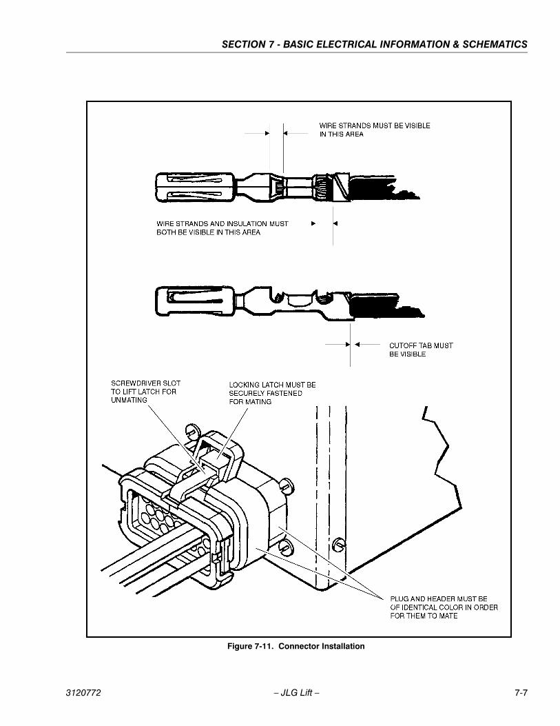
SECTION 7 - BASIC ELECTRICAL INFORMATION & SCHEMATICS
Figure 7-11. Connector Installation
3120772 – JLG Lift – 7-7

SECTION 7 - BASIC ELECTRICAL INFORMATION & SCHEMATICS
7.5 DEUTSCH CONNECTORS
DT/DTP Series Assembly
1. Grasp crimped contact about 25mm behind the con-tact barrel.
2. Hold connector with rear grommet facing you.
3. Push contact straight into connector grommet until aclick is felt. A slight tug will confirm that it is properlylocked in place.
4. Once all contacts are in place, insert wedgelock witharrow pointing toward exterior locking mechanism.The wedgelock will snap into place. Rectangularwedges are not oriented. Thy may go in either way.
NOTE: The receptacle is shown - use the same procedurefor plug.
DT/DTP Series Disassembly
1. Remove wedgelock using needlenose pliers or ahook shaped wire to pull wedge straight out.
2. To remove the contacts, gently pull wire backwards,while at the same time releasing the locking fingerby moving it away from the contact with a screw-driver.
3. Hold the rear seal in place, as removing the contactmay displace the seal.
Figure 7-12. DT/DTP Contact Installation
A B
C DFigure 7-13. DT/DTP Contact Removal
A B
C
7-8 – JLG Lift – 3120772

SECTION 7 - BASIC ELECTRICAL INFORMATION & SCHEMATICS
HD30/HDP20 Series Assembly
1. Grasp contact about 25mm behind the contactcrimp barrel.
2. Hold connector with rear grommet facing you.
3. Push contact straight into connector grommet until apositive stop is felt. A slight tug will confirm that it isproperly locked in place.
NOTE: For unused wire cavities, insert sealing plugs for fullenvironmental sealing
HD30/HDP20 Series Disassembly
1. With rear insert toward you, snap appropriate sizeextractor tool over the wire of contact to beremoved.
2. Slide tool along into the insert cavity until it engagescontact and resistance is felt.
3. Pull contact-wire assembly out of connector.
NOTE: Do Not twist or insert tool at an angle.
Figure 7-14. HD/HDP Contact Installation
A B
C
Figure 7-15. HD/HDP Locking Contacts Into Position
Figure 7-16. HD/HDP Contact Removal
A B
C
Figure 7-17. HD/HDP Unlocking Contacts
3120772 – JLG Lift – 7-9

SECTION 7 - BASIC ELECTRICAL INFORMATION & SCHEMATICS
PLATFORMWORKLIGHTS
RECEPTACLEAT PLATFORM
FOOTSWITCH
MAINVALVE
STEER /BRAKE
VALVE
PLATFORMCONSOLE
TOANALYZER
JIBVALVEJ1
J2J3
J5J4
J6J7 J8 J11
JIBVALVE
Figure 7-18. Electrical Components - Sheet 1 of 2
7-10 – JLG Lift – 3120772

SECTION 7 - BASIC ELECTRICAL INFORMATION & SCHEMATICS
BOOMLIMIT
SWITCHES
HORN
GROUNDCONTROL
BOX
BEACONLIGHT
POSI-TRACK/TILT MODULE
PUMP/MOTOR
SPEEDSENSOR
(LEFT BRAKE)
SPEED SENSOR(RIGHT BRAKE) BATTERY
CHARGER
POWERMODULE
(SHOWN HEREFOR CLARITY)
CONTROLMODULE(SHOWN HEREFOR CLARITY)
TOBATT.
B–
CONTACTORPLATE
TOBATTERYCHARGER
TO GROUNDCONTROL BOX
COVER
Figure 7-19. Electrical Components - Sheet 2 of 2
3120772 – JLG Lift – 7-11

SECTION 7 - BASIC ELECTRICAL INFORMATION & SCHEMATICS
Figure 7-20. Electrical Schematic - Sheet 1 of 2
7-12 – JLG Lift – 3120772

SECTION 7 - BASIC ELECTRICAL INFORMATION & SCHEMATICS
Figure 7-21. Electrical Schematic - Sheet 2 of 2
1870225 A
3120772 – JLG Lift – 7-13

SECTION 7 - BASIC ELECTRICAL INFORMATION & SCHEMATICS
Figure 7-22. Hydraulic Schematic - 300A - Sheet 1 of 2
7-14 – JLG Lift – 3120772

SECTION 7 - BASIC ELECTRICAL INFORMATION & SCHEMATICS
Figure 7-23. Hydraulic Schematic - 300A - Sheet 2 of 2
2792521 B
3120772 – JLG Lift – 7-15

SECTION 7 - BASIC ELECTRICAL INFORMATION & SCHEMATICS
Figure 7-24. Hydraulic Schematic - 300AJ - Sheet 1 of 2
7-16 – JLG Lift – 3120772

SECTION 7 - BASIC ELECTRICAL INFORMATION & SCHEMATICS
Figure 7-25. Hydraulic Schematic - 300AJ - Sheet 2 of 2
2792522 B
3120772 – JLG Lift – 7-17

SECTION 7 - BASIC ELECTRICAL INFORMATION & SCHEMATICS
Figure 7-26. Hydraulic Schematic - 300AJP - Sheet 2 of 2
7-18 – JLG Lift – 3120772

SECTION 7 - BASIC ELECTRICAL INFORMATION & SCHEMATICS
Figure 7-27. Hydraulic Schematic - 300AJP - Sheet 2 of 2
2792523 B
3120772 – JLG Lift – 7-19

SECTION 7 - BASIC ELECTRICAL INFORMATION & SCHEMATICS
NOTES:
7-20 – JLG Lift – 3120772


Corporate Office
JLG Industries, Inc.
1 JLG Drive
McConnellsburg PA. 17233-9533
USA
(717) 485-5161
(717) 485-6417
JLG Worldwide Locations
JLG Industries (Australia)P.O. Box 511911 Bolwarra RoadPort MacquarieN.S.W. 2444Australia
+61 2 65 811111
+61 2 65 810122
JLG Latino Americana Ltda.Rua Eng. Carlos Stevenson,80-Suite 7113092-310 Campinas-SPBrazil
+55 19 3295 0407
+55 19 3295 1025
JLG Industries (UK) LtdBentley HouseBentley AvenueMiddletonGreater ManchesterM24 2GP - England
+44 (0)161 654 1000
+44 (0)161 654 1001
JLG France SASZ.I. de Baulieu47400 FauilletFrance
+33 (0)5 53 88 31 70
+33 (0)5 53 88 31 79
JLG Deutschland GmbHMax-Planck-Str. 21D - 27721 Ritterhude - IhlpohlGermany
+49 (0)421 69 350 20
+49 (0)421 69 350 45
JLG Equipment Services Ltd.Rm 1107 Landmark North39 Lung Sum AvenueSheung Shui N. T.Hong Kong
(852) 2639 5783
(852) 2639 5797
JLG Industries (Italia) s.r.l.Via Po. 2220010 Pregnana Milanese - MIItaly
+39 029 359 5210
+39 029 359 5845
JLG Europe B.V.Polaris Avenue 632132 JH HoofddorpThe Netherlands
+31 (0)23 565 5665
+31 (0)23 557 2493
JLG PolskaUI. Krolewska00-060 WarsawaPoland
+48 (0)914 320 245
+48 (0)914 358 200
JLG Industries (Scotland)Wright Business Centre1 Lonmay RoadQueenslie, Glasgow G33 4ELScotland
+44 (0)141 781 6700
+44 (0)141 773 1907
Plataformas Elevadoras JLG Iberica, S.L.Trapadella, 2P.I. Castellbisbal Sur08755 Castellbisbal, BarcelonaSpain
+34 93 772 4700
+34 93 771 1762
JLG Sverige ABEnkopingsvagen 150Box 704SE - 176 27 JarfallaSweden
+46 (0)850 659 500
+46 (0)850 659 534
www.jlg.com
3120772


