32

Fabco Automotive CorporationService and Parts Manual
Models TC-65, TC-80, TC-110 and PTO-110
T A B L E O F C O N T E N T S
I. Operating Instructions VII. Torque Specifications 24
A. Front DriveB. Underdrive (TC-65 Only)C. Power Take-Off
3 VIII. Parts Manual33
25
II. Lubrication
A. Transfer Case Oil ChangeB. Draining OilC. Refilling OilD. InspectionE. Operating TemperatureF. Shift Cylinder Inspection
P A R T S M A N U A LSTARTS ON PAGE 255
55555
Ill. Transfer Case Removal and Installation
A. Removal from Vehicle 6B. Installation into Vehicle 6
IV. Transfer Case Disassembly
A. General Precautions for Disassembly 7B. Preparation for Disassembly 7C. Shift Cylinder Disassembly 7D. PTO and Declutch Disassembly 8E. Splitting the Main Housing 9F. Input Shaft Disassembly 9G. Intermediate Shaft Disassembly 10H. Output Shaft Disassembly 10I. Oil Pump Disassembly 11
V. Cleaning and Inspection
A. Choice of Cleaning MethodsB. Drying and Corrosion InhibitionC. Inspection
121212
VI. Transfer Case Assembly
A. General Precautions for ReassemblyB. Input Shaft AssemblyC. Intermediate Shaft AssemblyD. Output Shaft AssemblyE. Main Housing AssemblyF. Declutch and PTO AssemblyG. Shift Cylinder Assembly
131415161720
and Adjustment 22H. Oil Pump Assembly 23I. Final Assembly 23
625 403A Copyright © 1984 by Fabco Automotive,
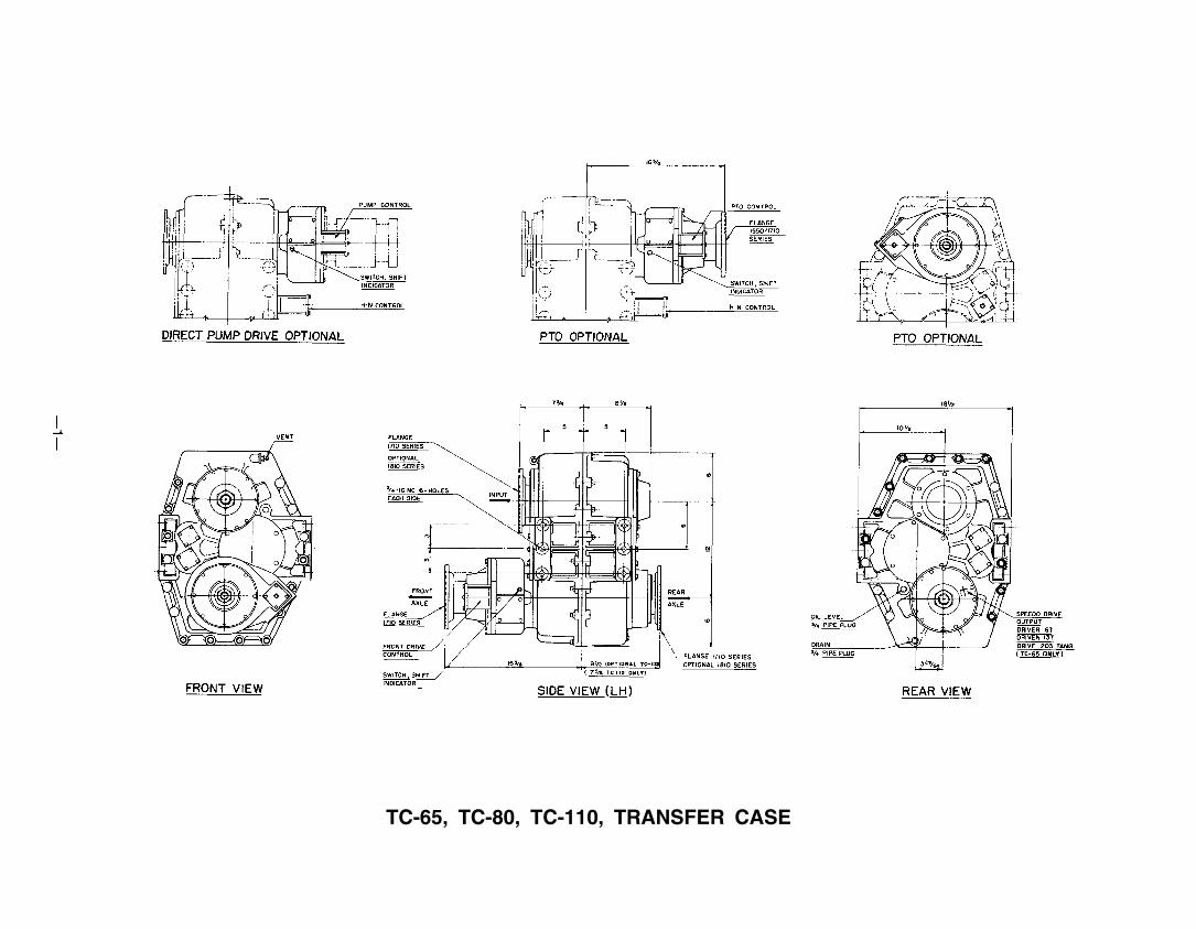
TC-65, TC-80, TC-110, TRANSFER CASE
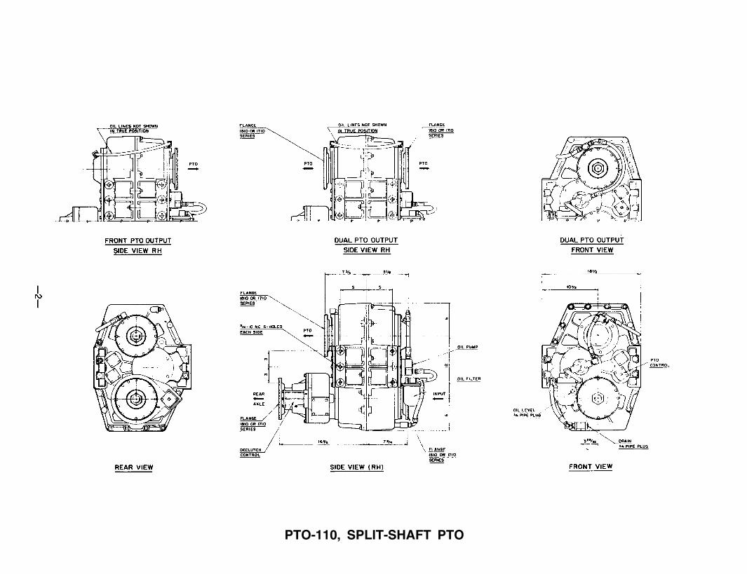
PTO-110, SPLIT-SHAFT PTO
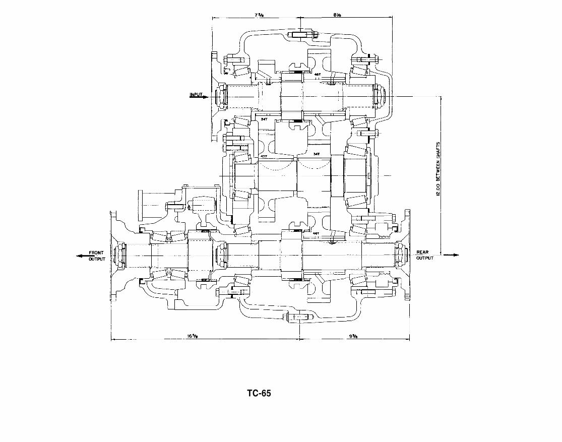
TC-65

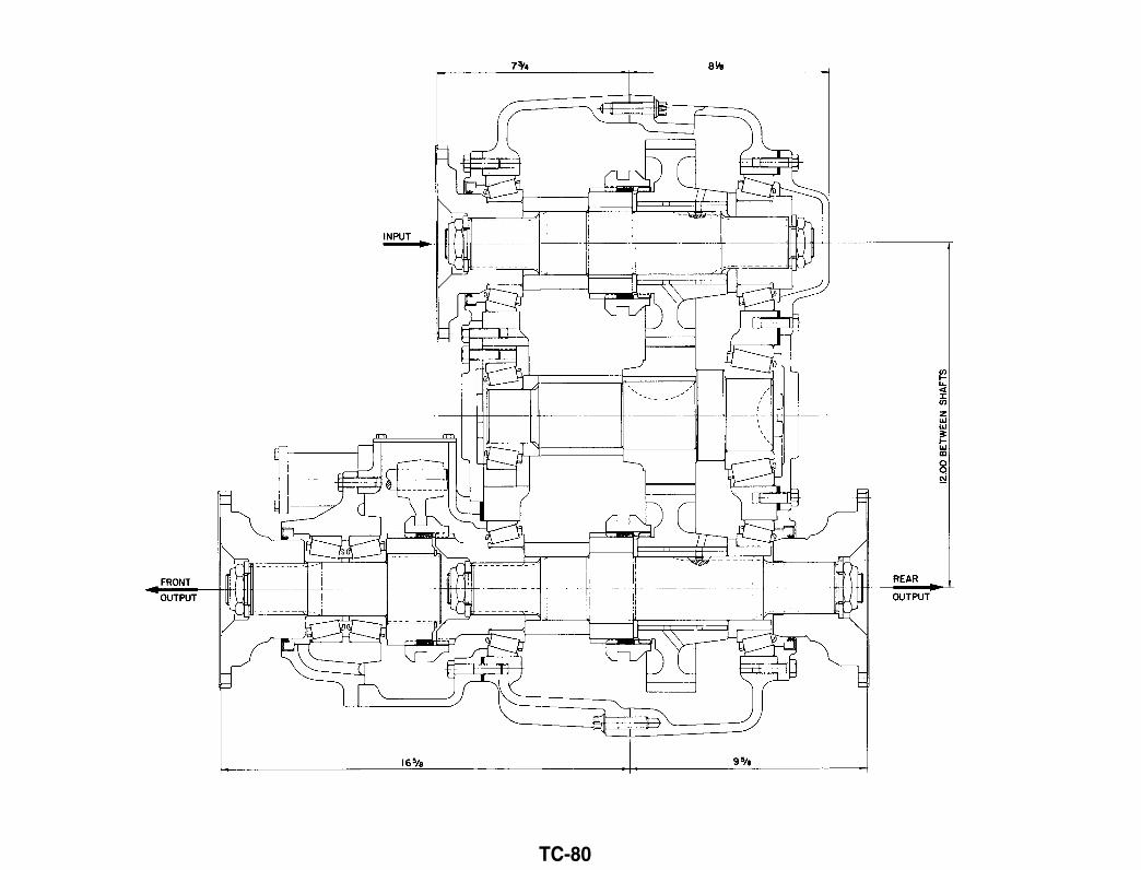
TC-80

TC-110
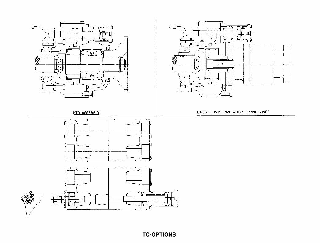
TC-OPTIONS

PTO-110

Front Drive
I . OPERATING INSTRUCTIONS
When traveling through sand, loose dirt, mud, snowor ice, or when ascending grades where the rearwheels might spin, shift to front wheel drive forbetter traction. Shift before the truck is in trouble.Engagement and disengagement of the front axlecan best be made while the engine is pulling lightly.It can be shifted at any speed provided the rearwheels are not spinning. An indicator switch isactuated when the shifter shaft is in the engagedposition.
Underdrive (TC-65 only)
When slow, positive pulling power is desired, shift tounderdrive. Underdrive may be used to obtain aconvenient combination with third or direct forclimbing some grades. The transfer case should beshifted between high and low range only when thetruck is stopped.
Power Take-Off
If the transfer case is equipped with a power take-offor a PTO mounted hydraulic pump, it can beoperated while the vehicle is moving or stationary.To engage vehicles fitted with an automatictransmission, put transmission and transfer case ingear, apply the brakes and shift the PTO or hydraulicpump into the engaged position, while the engine isidling. After the PTO has been engaged, shift thetransmission and transfer case to the desired gear.An indicator switch is actuated when the shiftershaft is in the engaged position.
To disengage the PTO or hydraulic pump, shift thetransmission to neutral (manual or automatic),allow the machinery to come to rest, then shift thecontrol to disengage.
—3—
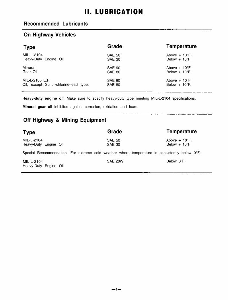
II. LUBRICATIONRecommended Lubricants
On Highway Vehicles
Type Grade Temperature
MIL-L-2104 SAE 50Heavy-Duty Engine Oil SAE 30
Mineral SAE 90Gear Oil SAE 80
MIL-L-2105 E.P. SAE 90Oil, except Sulfur-chlorine-lead type. SAE 80
Above + 10°F.Below + 10°F.
Above + 10°F.Below + 10°F.
Above + 10°F.Below + 10°F.
Heavy-duty engine oil. Make sure to specify heavy-duty type meeting MIL-L-2104 specifications.
Mineral gear oil inhibited against corrosion, oxidation and foam.
Off Highway & Mining Equipment
Type Grade Temperature
MIL-L-2104 SAE 50 Above + 10°F.Heavy-Duty Engine Oil SAE 30 Below + 10°F.
Special Recommendation—For extreme cold weather where temperature is consistently below 0°F:
MIL-L-2104Heavy-Duty Engine Oil
SAE 20W Below 0°F.
—4—

II. LUBRICATIONNOTE: Oil Change and Inspection Recommendations:
The oil change and inspection periods described below are based on the average use and operating conditionsthe transfer case may encounter. It is recommended that the individual owner make a periodic lab analysis ofthe lubricant to determine contamination based on the individual’s own operating conditions. With this datathe individual owner can better determine their own oil change and inspection periods.
A. Transfer Case Oil Change D. Inspection
Transfer case lubricant should be changed on allnew transfer cases after the first 3,000 to 5,000 miles(on-highway), or first 40 hours (off-highway); there-after, oil changes should be done at the followingintervals:
Gear oil level is to be maintained at the level of the fillplug at all times. Check at the following intervals:
Off-Highway Service
10,000 - 15,000 miles
Highway Service 1,000 milesOff-Highway Service 40 hours
E. Operating Temperature
(Logging, dirt moving, mining500-750 hours,
as indicated by operation and contamination oflubricant.
The operating temperature of the transfer caseshould never exceed 250°F (120°C). Extensiveoperation at temperatures exceeding 250°F willresult in rapid breakdown of the oil and shortenthe transfer case life.
B. Draining Oil F. Shift Cylinder InspectionDraining is best accomplished after the vehicle hasbeen operated briefly, allowing the oil to becomewarm and flow freely. Remove both drain and fillplugs and allow housing to empty completely. Aftertransfer case has been drained and before it isrefilled, the case should be thoroughly flushed withclean flushing oil or kerosene.
With every oil change the air shift cylinder lines andvalves should be inspected for leaks and possiblemalfunctioning. Low pressure conditions can causepartial clutch tooth engagement which may result in“gear jumping” and premature wear.
C. Refilling Oil
If the transfer case has been removed from thevehicle for service, it is best to refill the oil after thetransfer case has been reinstalled into the vehicle.
Clean and replace drain plug and fill the transfercase with appropriate gear oil with the vehicle onlevel ground (see recommended lubricant chart).Fill transfer case to the level of the fill plug, meteringapproximately 10½ quarts of gear oil into thetransfer case. The exact amount may di f ferdepending upon the inclination of the transfer case.Always fill to the level of the fill plug. Replace fill plugand examine transfer case for leaks around plugsand gasket sealed areas.
Do not overfill the transfer case.
—5—
and associated operations)..............
On-Off Highway Service.........
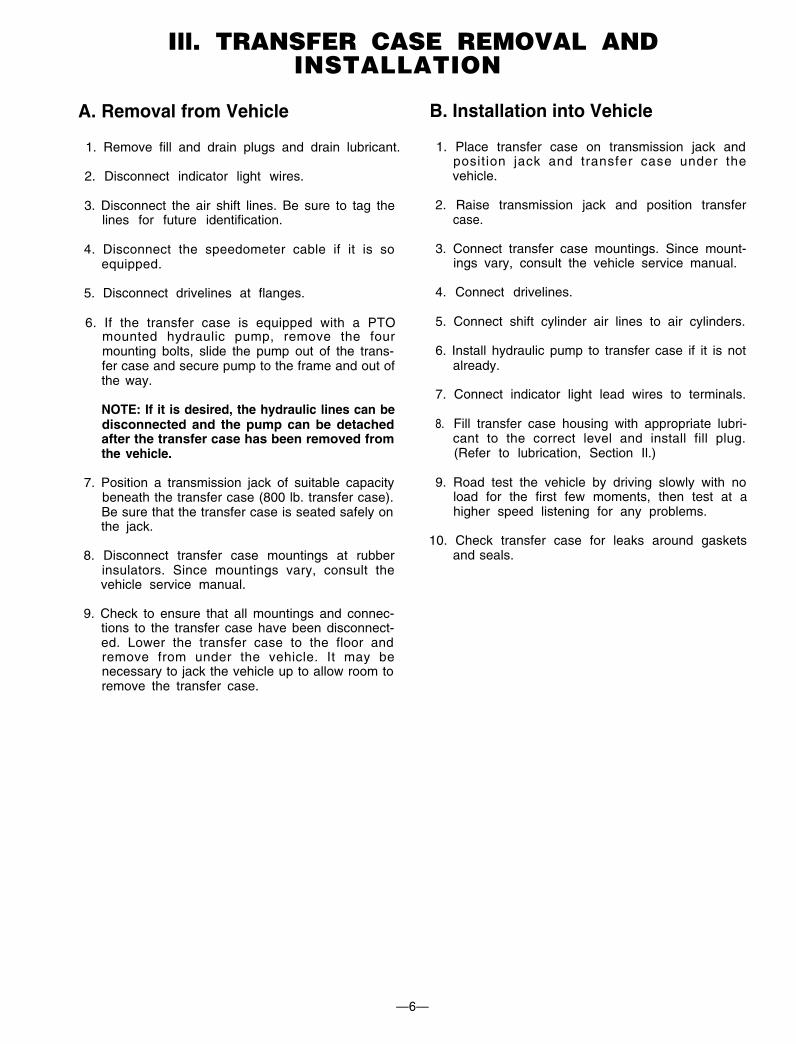
Ill. TRANSFER CASE REMOVAL ANDINSTALLATION
A. Removal from Vehicle
1. Remove fill and drain plugs and drain lubricant.
2. Disconnect indicator light wires.
3. Disconnect the air shift lines. Be sure to tag thelines for future identification.
4. Disconnect the speedometer cable if it is soequipped.
5. Disconnect drivelines at flanges.
6. If the transfer case is equipped with a PTOmounted hydraulic pump, remove the fourmounting bolts, slide the pump out of the trans-fer case and secure pump to the frame and out ofthe way.
NOTE: If it is desired, the hydraulic lines can bedisconnected and the pump can be detachedafter the transfer case has been removed fromthe vehicle.
7. Position a transmission jack of suitable capacitybeneath the transfer case (800 lb. transfer case).Be sure that the transfer case is seated safely onthe jack.
8. Disconnect transfer case mountings at rubberinsulators. Since mountings vary, consult thevehicle service manual.
9. Check to ensure that all mountings and connec-tions to the transfer case have been disconnect-ed. Lower the transfer case to the floor andremove from under the vehicle. It may benecessary to jack the vehicle up to allow room toremove the transfer case.
B. Installation into Vehicle
1. Place transfer case on transmission jack andposition jack and transfer case under thevehicle.
2. Raise transmission jack and position transfercase.
3. Connect transfer case mountings. Since mount-ings vary, consult the vehicle service manual.
4. Connect drivelines.
5. Connect shift cylinder air lines to air cylinders.
6. Install hydraulic pump to transfer case if it is notalready.
7. Connect indicator light lead wires to terminals.
8. Fill transfer case housing with appropriate lubri-cant to the correct level and install fill plug.(Refer to lubrication, Section Il.)
9. Road test the vehicle by driving slowly with noload for the first few moments, then test at ahigher speed listening for any problems.
10. Check transfer case for leaks around gasketsand seals.
—6—
IV. TRANSFER CASE DISASSEMBLY
A. General Precautions forDisassembly
IMPORTANT: Read this section before starting thedisassembly procedures.
It is assumed in the disassembly instructions that thelubricant has been drained from the transfer caseand the transfer case has been removed from thechassis.
Follow each procedure closely in each section, mak-ing use of both tests and pictures. Refer to the ex-ploded views located in Section VIII as an aid in dis-assembly.
1.
2.
3.
4.
5.
6.
7.
8.
The outside of the unit should be cleaned beforestarting the disassembly. If steam cleaning,ensure that breather and air fittings are coveredto prevent water from entering assembly.
Cleanliness—Provide a clean place to work. It isimportant that no dirt or foreign material entersthe unit during repairs.
Position the transfer case in a stand suitable tosupport the transfer case. A specially fabricatedstand that can rotate the case is extremely use-ful.
Assemblies—When disassembling the variousassemblies, lay all parts on a clean bench in thesame sequence as removed. This procedure willsimplify reassembly and reduce the possibilityof lost parts.
Bearings—Carefully wash and relubricate allbearings as removed and protectively wrap untilready for use. Remove bearings with pullers de-signed for this purpose, or in a manner whichwill not damage those bearings that will be re-used.
Snap Rings—Remove snap rings with pliers orspecial tools designed for this purpose. Ringsremoved in this manner can be reused.
When necessary to apply a force to remove apart, use of a puller or press would be preferred.However, sometimes it may be necessary to usea soft hammer or mallet.
The PTO-110, a variant configuration of the TC-110, is used for a Split-Shaft Power Take Off.Refer to the TC-110 instructions for assemblyand disassembly. Minor differences are noted inthe TC-110 text.
B.
1.
2.
C. Shift Cylinder Disassembly
1.
2.
3.
4.
5.
(High-Neutral-Underdrive)
The PTO-110 is installed reversed, so TC-110front is the same as PTO-110 back, and shaftrotations are reversed. The PTO-110 oil pump isassembled to pump in reverse rotation, so trans-fer case and Power Take Off oil pumps areNOT interchangeable.
Preparation for Disassembly
After removing the transfer case from the vehi-cle, remove any mounting brackets still attachedto the transfer case.
Remove oil lines if so equipped.
Remove four bolts from the shift cylinder capand remove cap from shift cylinder. Discard O-ring from cylinder cap, if replacement is neces-sary.
Remove shift cylinder tube from the shift cylin-der adapter tube located in the housing, ex-posing piston.
Disassemble shift piston from the shift shaft anddiscard O-ring and felt wiper, if replacement isnecessary.
Remove shift shaft spring and plastic stop ringfrom the shift shaft or from the shift cylinderadapter tube located in the housing.
Remove shift cylinder adapter tube from hous-ing. Discard O-rings from the adapter, if replace-ment is necessary.
—7—
D. PTO and Declutch Disassembly
The declutch assembly and PTO are essentiallyidentical. Hereafter, reference will be made tothe declutch only. For cases equipped with PTO,use the instructions for declutch disassembly,inspection and reassembly exactly as given.
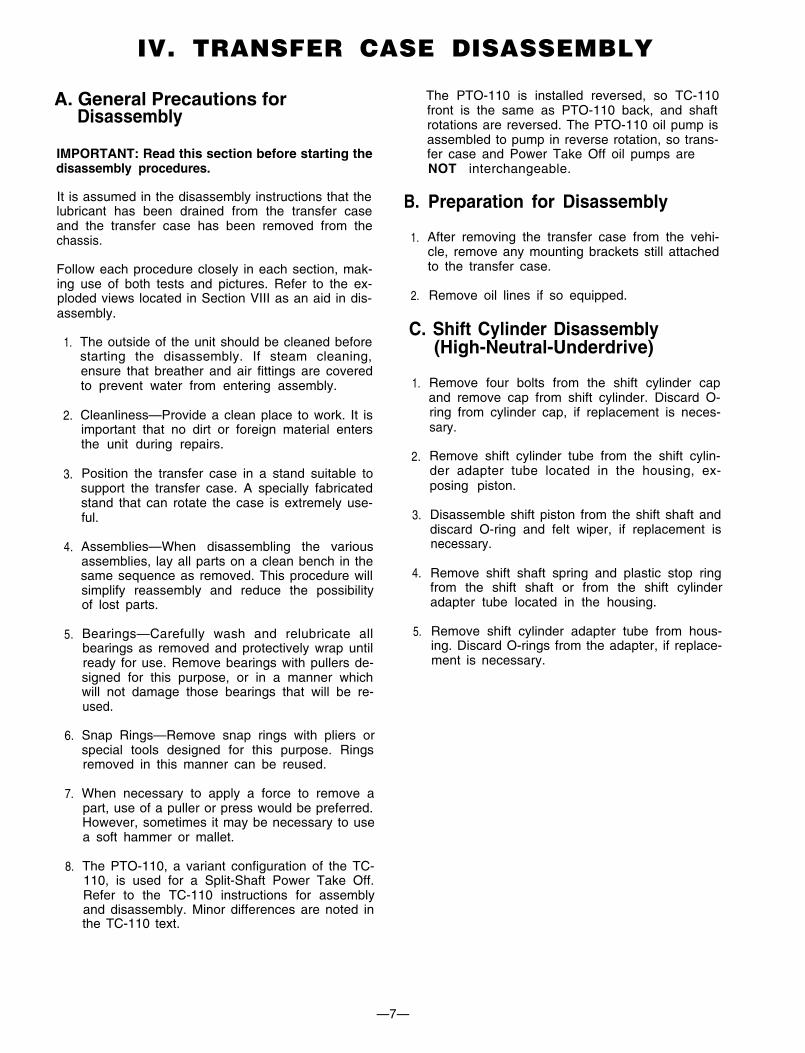
1. Remove eight capscrews holding declutch car-rier to declutch housing.
2. Tap carrier to loosen and withdraw carrier andoutput shaft assembly (see fig. 1).
3. Unscrew indicator light switch from declutchhousing and remove spacer washers. Removeswitch actuator pin from inside declutch hous-ing using a magnet or turn upside down anddump it out.
Fig. 1
4. Remove four capscrews from declutch coverplate and remove cover plate.
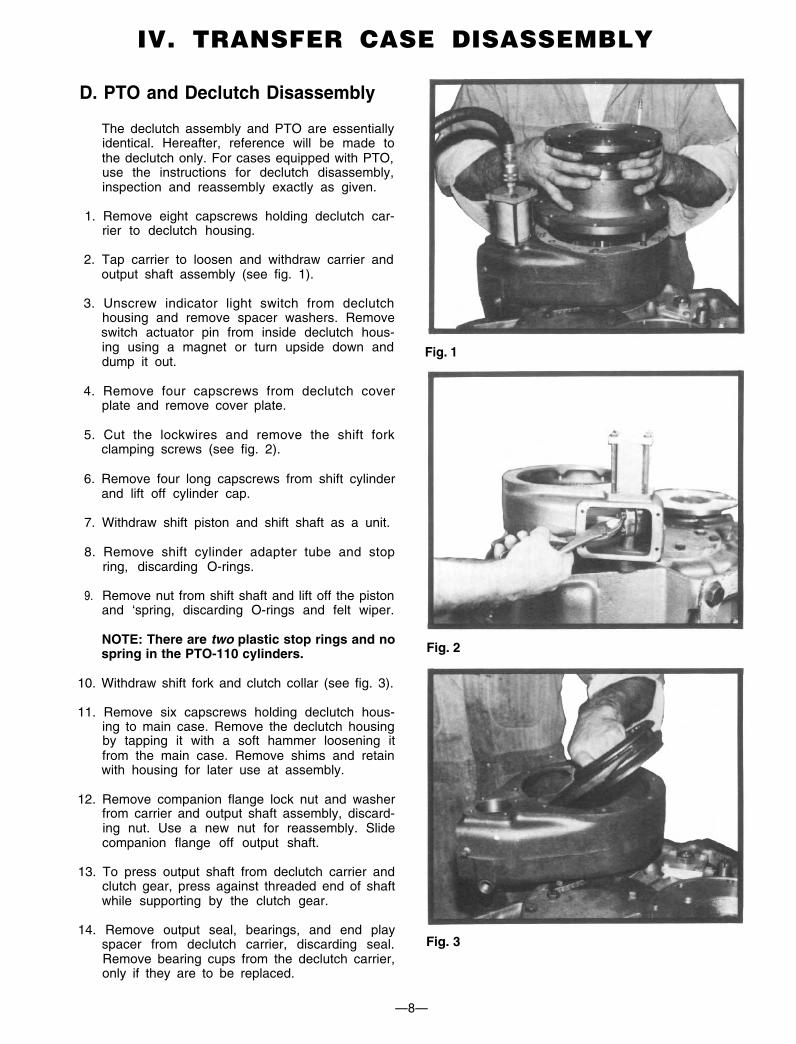
5. Cut the lockwires and remove the shift forkclamping screws (see fig. 2).
6. Remove four long capscrews from shift cylinderand lift off cylinder cap.
7. Withdraw shift piston and shift shaft as a unit.
8. Remove shift cylinder adapter tube and stopring, discarding O-rings.
9. Remove nut from shift shaft and lift off the pistonand ‘spring, discarding O-rings and felt wiper.
NOTE: There are two plastic stop rings and nospring in the PTO-110 cylinders. Fig. 2
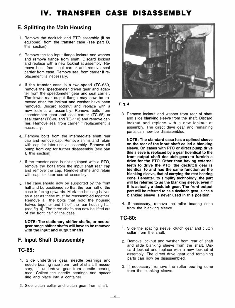
10. Withdraw shift fork and clutch collar (see fig. 3).
11. Remove six capscrews holding declutch hous-ing to main case. Remove the declutch housingby tapping it with a soft hammer loosening itfrom the main case. Remove shims and retainwith housing for later use at assembly.
12. Remove companion flange lock nut and washerfrom carrier and output shaft assembly, discard-ing nut. Use a new nut for reassembly. Slidecompanion flange off output shaft.
13. To press output shaft from declutch carrier andclutch gear, press against threaded end of shaftwhile supporting by the clutch gear.
14. Remove output seal, bearings, and end playspacer from declutch carrier, discarding seal.Remove bearing cups from the declutch carrier,only if they are to be replaced.
Fig. 3
—8—
IV. TRANSFER CASE DISASSEMBLY
E. Splitting the Main Housing
1. Remove the declutch and PTO assembly (if soequipped) from the transfer case (see part D,this section).
2. Remove the top input flange locknut and washerand remove flange from shaft. Discard locknutand replace with a new locknut at assembly. Re-move bolts from seal carrier and remove sealcarrier from case. Remove seal from carrier if re-placement is necessary.
3. If the transfer case is a two-speed (TC-659,remove the speedometer driven gear and adap-ter from the speedometer gear and seal carrier.The lower rear output flange may now be re-moved after the locknut and washer have beenremoved. Discard locknut and replace with anew locknut at assembly. Remove bolts fromspeedometer gear and seal carrier (TC-65) orseal carrier (TC-80 and TC-110) and remove car-rier. Remove seal from carrier if replacement isnecessary.
4. Remove bolts from the intermediate shaft rearcap and remove cap. Remove shims and retainwith cap for later use at assembly. Remove oilpump from cap for further disassembly (see partI, this section).
5. If the transfer case is not equipped with a PTO,remove the bolts from the input shaft rear capand remove the cap. Remove shims and retainwith cap for later use at assembly.
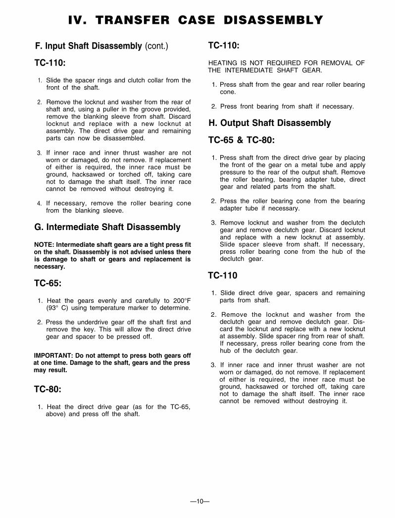
6. The case should now be supported by the fronthalf and be positioned so that the rear half of thecase is facing upwards. Mark the housing halvesas a set as these must be reassembled together.Remove all the bolts that hold the housinghalves together and lift off the rear housing half(see fig. 4). The three shafts can now be lifted outof the front half of the case.
NOTE: The stationary shifter shafts, or neutralgear range shifter shafts will have to be removedwith the input and output shafts.
F. Input Shaft Disassembly
TC-65:
1. Slide underdrive gear, needle bearings andneedle bearing race from front of shaft. If neces-sary, lift underdrive gear from needle bearingrace. Collect the needle bearings and spacerring and place into a container.
2. Side clutch collar and clutch gear from shaft.
Fig. 4
3. Remove locknut and washer from rear of shaftand slide blanking sleeve from the shaft. Discardlocknut and replace with a new locknut atassembly. The direct drive gear and remainingparts can now be disassembled.
NOTE: The standard case has a splined sleeveon the rear of the input shaft called a blankingsleeve. On cases with PTO or direct pump drivethis sleeve is replaced by a gear (identical to thefront output shaft declutch gear) to furnish adrive for the PTO. Other than having externalteeth to drive the PTO, the declutch gear isidentical to and has the same function as theblanking sleeve, that of carrying the rear bearingcone. Hereafter, to simplify technology, the partwill be referred to as the blanking sleeve, even ifit is actually a declutch gear. The front outputpart will be referred to as a declutch gear, since ablanking sleeve is never used in this position.
4. If necessary, remove the roller bearing conefrom the blanking sleeve.
TC-80:
1.
2.
3.
Slide the spacing sleeve, clutch gear and clutchcollar from the shaft.
Remove locknut and washer from rear of shaftand slide blanking sleeve from the shaft. Dis-card locknut and replace with a new locknut atassembly. The direct drive gear and remainingparts can now be disassembled.
If necessary, remove the roller bearing conefrom the blanking sleeve.
—9—
IV. TRANSFER CASE DISASSEMBLY
F. Input Shaft Disassembly (cont.)
TC-110:
1.
2.
Slide the spacer rings and clutch collar from thefront of the shaft.
Remove the locknut and washer from the rear ofshaft and, using a puller in the groove provided,remove the blanking sleeve from shaft. Discardlocknut and replace with a new locknut atassembly. The direct drive gear and remainingparts can now be disassembled.
3. If inner race and inner thrust washer are notworn or damaged, do not remove. If replacementof either is required, the inner race must beground, hacksawed or torched off, taking carenot to damage the shaft itself. The inner racecannot be removed without destroying it.
4. If necessary, remove the roller bearing conefrom the blanking sleeve.
G. Intermediate Shaft Disassembly
NOTE: Intermediate shaft gears are a tight press fiton the shaft. Disassembly is not advised unless thereis damage to shaft or gears and replacement isnecessary.
TC-65:
1. Heat the gears evenly and carefully to 200°F(93° C) using temperature marker to determine.
2. Press the underdrive gear off the shaft first andremove the key. This will allow the direct drivegear and spacer to be pressed off.
IMPORTANT: Do not attempt to press both gears offat one time. Damage to the shaft, gears and the pressmay result.
TC-80:
1. Heat the direct drive gear (as for the TC-65,above) and press off the shaft.
TC-110:
HEATING IS NOT REQUIRED FOR REMOVAL OFTHE INTERMEDIATE SHAFT GEAR.
1. Press shaft from the gear and rear roller bearingcone.
2. Press front bearing from shaft if necessary.
H. Output Shaft Disassembly
TC-65 & TC-80:
1. Press shaft from the direct drive gear by placingthe front of the gear on a metal tube and applypressure to the rear of the output shaft. Removethe roller bearing, bearing adapter tube, directgear and related parts from the shaft.
2. Press the roller bearing cone from the bearingadapter tube if necessary.
3. Remove locknut and washer from the declutchgear and remove declutch gear. Discard locknutand replace with a new locknut at assembly.Slide spacer sleeve from shaft. If necessary,press roller bearing cone from the hub of thedeclutch gear.
TC-110
1. Slide direct drive gear, spacers and remainingparts from shaft.
2. Remove the locknut and washer from thedeclutch gear and remove declutch gear. Dis-card the locknut and replace with a new locknutat assembly. Slide spacer ring from rear of shaft.If necessary, press roller bearing cone from thehub of the declutch gear.
3. If inner race and inner thrust washer are notworn or damaged, do not remove. If replacementof either is required, the inner race must beground, hacksawed or torched off, taking carenot to damage the shaft itself. The inner racecannot be removed without destroying it.
—10—
IV. TRANSFER CASE DISASSEMBLY

I. Oil Pump Disassembly
1. Place pump in a vise, shaft facing up, so that onejaw grips across two ports. Use care to avoid dis-torting pump housing by excessive tighteningof vise.
2. Remove any burrs on shaft drive tang.
3. Remove housing plug with a suitable spannerwrench.
4. Remove from vise and punch match marks (orpaint dab) on cover and body for reassembly.
5. Remove capscrews, cover, idler, and rotor fromhousing.
6. Check pump housing, rotor, idler gear, idlerpin and crescent for wear, chipped or brokenteeth.
7. Housing bore and rotor O.D. may be checked forwear by positioning rotor in the housing andcheck for clearance in the bearing. The shaftmust turn freely without any detectable sideplay. Any side play will require replacement ofhousing, rotor or both. If both housing and rotorrequire replacing, it is economically advisableto replace the pump.
NOTE: The PTO-110 pump has the cover re-versed to allow flow in the opposite rotationdirection. Note the position of the notch in thecover prior to disassembly.
—11—
IV. TRANSFER CASE DISASSEMBLY
A. Choice of Cleaning Methods
1. Steam may be used for external cleaning ofcompletely assembled units. Care must be takento ensure that water is kept out of the assemblyby tightly closing breather caps and otheropenings.
2. Rough parts such as the housing, which are toolarge to conveniently clean with solvents, maybe immersed in a hot solution tank containing amild alkaline solution. Parts cleaned in hotsolution tanks must be rinsed thoroughly toprevent damage by traces of alkaline material.
3. Parts with ground or polished surfaces, such asbearings, gears, and shafts, should be cleanedwith emulsion cleaners or petroleum solvents.Alkaline hot solution tanks may damage themachined surfaces and such cleaning methodsshould be avoided.
B. Drying and Corrosion Inhibition
Soft clean shop towels should be used to dry partsafter cleaning. Compressed air may be used to cleaninaccessible areas of large parts such as the hous-ing. Bear ings should not be spun dry wi thcompressed air, as the lack of lubrication may causedamage to the mating surfaces.
Dried parts should be immediately coated with alight oil or corrosion inhibitor to prevent corrosiondamage. Parts which are to be stored should also bewrapped in heavy waxed paper.
C. Inspection
Prior to reassembly, parts which are to be reusedmust be carefully inspected for signs of wear ordamage. Replacement of such parts can preventcostly downtime at a future date.
All bearing surfaces, including roller bearing cupsand cones, should be examined for pitting, wear, oroverheating. Gears also may show pits, as well asscoring and broken teeth. Shafts may be nicked ormarred, or may have damaged threads. Parts whichshow any signs of damage should be repaired orreplaced.
Check all shift forks and slots in sliding clutches forextreme wear or discoloration from heat. Checkengaging teeth of sliding clutches for partialengagement pattern.
—12—
V. CLEANING AND INSPECTION

A. General Precautions for B. Input Shaft AssemblyReassembly TC-65 & TC-80:
IMPORTANT: Read this section before startingreassembly procedure.
Make sure that the interior of the transfer case isclean. It is important that dirt be kept out of transfercase during reassembly. Use certain precautions, aslisted below, during reassembly.
1. Gaskets — Clean all gasket surfaces of pastgasket material. Use new gaskets throughoutthe transfer case as it is being rebuilt.
2. Bolts — To prevent oil leakage, use PermatexForm-A-Gasket #2 pliable setting sealant orequal on all threads. See torque specificationsfor recommended torque, Section VII.
3. Assembly — Refer to the exploded views in theparts manual (Section VIII) as a guide to reas-sembly.
Fig. 5—TC-65 Input Shaft Assembly with BlankingSleeve
4. Initial Lubrication — Coat all thrust washers,splines and seals with lubriplate during installa-tion to provide initial lubrication, preventingscoring and galling.
5. Bearings — Press or drive bearing races byapplying force to inner race or outer race,whichever is being installed.
6. Universal Joint Companion Flanges — Pull thecompanion flanges tightly into place with thelocknuts (old locknuts may be used for pulling,then replaced with new); tighten to propertorque. Failure to pull the flange tightly intoplace will not seat the bearings properly, caus-ing erroneous end play readings and possibledamage to bearings, shafts, and gears.
7. Inspect all spacer washers and rings for wear.The width or thickness of each spacer washer orring has been noted in the assembly proceduresand each spacer should be measured with amicrometer for proper size. Worn spacersshould be replaced.
Fig. 6—TC-65 Input Shaft Assembly with PTO Gear
8. The clutch collar shift fork slot is offset, which isindicated in Fig. 5. The long side can be deter-mined by examining the collar for the externalshort extended hub. This short hub, referred toin the assembly instructions, must always facethe mating gear clutch teeth, whether in the de-clutch housing, PTO housing or main case.
Fig. 7—TC-80 Input Shaft Assembly with PTO Gear
—13—
VI. TRANSFER CASE ASSEMBLY
B. Input Shaft Assembly (continued)
TC-65 & TC-80: (See Fig. 5, 6 and 7)
rear of the shaft. Slide the clutch collar onto theteeth of the clutch gear. The side of the collarwith the short hub is to face the rear of the shaft(see fig. 5)
1. Place input shaft thrust washer (.148 thick) onbench. Liberally grease inside diameter ofdirect drive and outside diameter of needlebearing race. Place front of direct drive gear(side of gear with clutch teeth) on thrust washer.Place needle bearing race inside the gear withthe bearing race lock pin facing the rear of thegear (or up). Grease needle bearings and installa row of needle bearings between gear and race.
NOTE: Install 62 needle bearings only in eachrow. One extra needle can be packed into eachrow, but this makes the rollers too tight, invaria-bly causing rubbing, heating and eventualfailure of the bearing pack, gear and shaft.
6. Place direct drive gear assembly (including gearspacer ring and thrust washer) over the shaftaligning inner race lock pin with elongatedgroove in shaft and against the clutch gear. Theclutch teeth of the gear must face the front of theshaft.
7. Press the bearing cone over the blanking sleevehub and slide the sleeve over the shaft splinesand secure with the washer and locknut. Tightennut to correct torque. Check thrust washerclearance as above, .015-.020.
Install a spacer ring, tap the needle bearings andspacer ring against the shoulder of the race witha punch and install next row of bearings.
8. Set the shaft aside for installation into the fronthalf of the main case. Refer to Part E, page 16, forthis assembly. Remove the flange from the shaftthat was used to support the shaft during assem-bly, making sure to retain underdrive gear,needles and inner race in position.
assembly with chamfered inside diameter facinginside of gear.
3. Two-speed case only (TC-65): Grease insidediameter of underdrive gear and outsidediameter of needle bearing race. Place needlebearing race on the bench with the flange facingdown. Place underdrive gear onto the race withthe clutch teeth facing up. Grease needle bear-ings and install a row of needle bearings be-tween gear and race.
NOTE: Install 62 needle bearings only in eachrow. One extra needle can be packed into eachrow, but this makes the rollers too tight, invaria-bly causing rubbing, heating and eventualfailure of the bearing pack, gear and shaft.
Install a spacer ring, tap the needle bearings andspacer ring against the shoulder of the race witha punch and install next row of bearings.
Fig. 8
4. Two-speed case only (TC-65): Install the frontside of the input shaft (short journal) through theunderdrive gear assembly. (The flange of the
front of the shaft and the clutch teeth of the gearare to face the center of the shaft). Align theinner race lock pin with the elongated groove inthe journal and slide gear on all the way. Withinner race pressed tightly against inner thrustwasher, check with a feeler gauge for .015-.020clearance between gear hub and thrust washer.
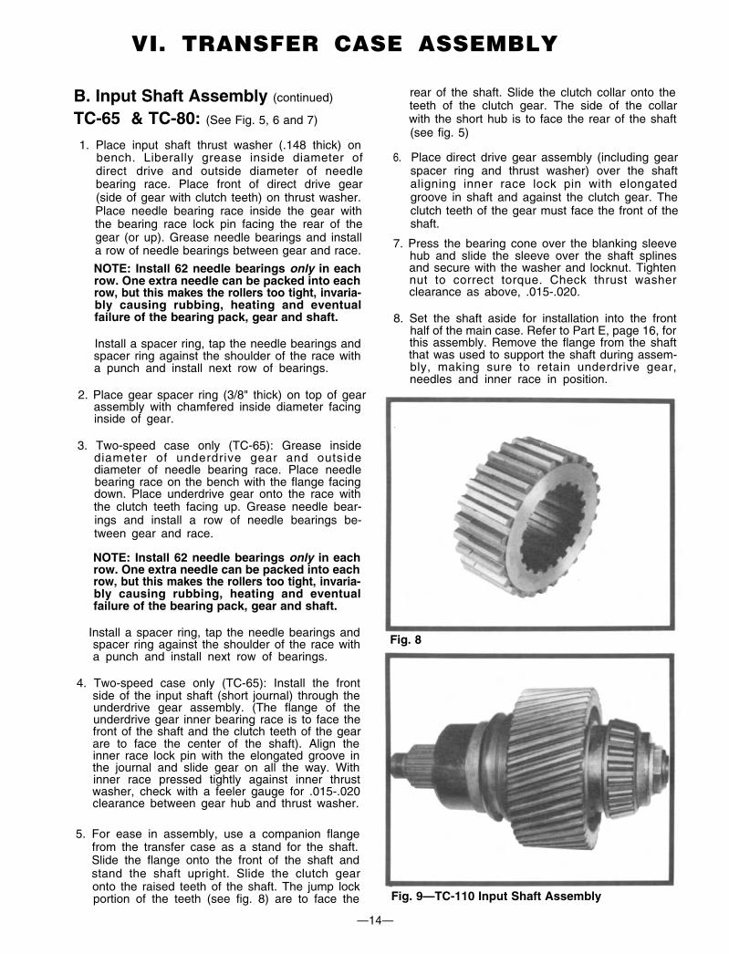
5. For ease in assembly, use a companion flangefrom the transfer case as a stand for the shaft.Slide the flange onto the front of the shaft andstand the shaft upright. Slide the clutch gearonto the raised teeth of the shaft. The jump lockportion of the teeth (see fig. 8) are to face the Fig. 9—TC-110 Input Shaft Assembly
—14—
VI. TRANSFER CASE ASSEMBLY
underdrive gear inner bearing race is to face the
2. Place gear spacer ring (3/8" thick) on top of gear

B. Input Shaft Assembly (continued)
TC-110: (see fig. 9)
1.
2.
3.
4.
5.
C. Intermediate Shaft Assembly
If the inner thrust washer and needle bearingrace have been removed from the rear of the
over the shaft and against the raised teeth of thegear. Oil groove side of washer to face outwardsand toward where the direct drive gear will beplaced. Heat the inner race in an oven to about200-250°, drop over shaft and tap down to theinner thrust washer with a suitable driver (theroller bearing inner race must be snug againstthe inner thrust washer).
Slide two roller bearing assemblies and spacerring over the roller bearing inner race located atthe rear of the shaft. Grease the roller bearingassemblies and the inner diameter of the directdrive gear. Slide the gear over the rear of theshaft. Place the gear spacer ring (5&” thick) overthe rear of the shaft and against the gear. Oilgroove side of washer must face gear.
Press the roller bearing cone over the blankingsleeve. Slide the blanking sleeve onto the splineslocated at the rear of the shaft. Secure blankingsleeve to shaft with the washer and locknut.Tighten locknut to correct torque. Check thrustclearance as before, .015-.020.
Slide clutch collar over the front of the shaft andover the raised teeth of the input shaft (short hubto face direct drive gear, see fig. 5). Slide spacerring (21/32” thick) over front of shaft and onto theraised teeth of shaft. Slide spacer ring (13’/32”thick) over front of shaft and onto the raised hubportion of the shaft past the splines. The innerdiameter chamfer of the spacer is to face thedirect drive gear.
Set the input shaft aside for installation into thefront half of the main case. Refer to part E, page16 for this assembly. (Be sure to hold the frontspacer ring as the shaft is dropped into the frontof the case so the parts do not slide from theshaft.)
TC-65 & TC-80: (See fig. 10 and fig. 11)1. Tap direct drive gear woodruff key into the slot
located in the center of the shaft. Heat directdrive gear in oil (or in an oven) to 200°F (93” C).Press the shaft into the gear by placing the frontof the gear (coned side) on a metal tube andapplying pressure to the rear of the shaft. Besure the woodruff key is mating properly withthe slot in the gear.
2. TC-65 only: Slide the spacer ring (.333 thick)over front of shaft and against direct drive gear.
3.
4.
5.
Tap underdrive gear woodruff key into the slot.Heat underdrive gear in oil (or in an oven) to200°F (93°C) and press the shaft into the gearby placing front of the gear (flat side) on a metaltube and applying pressure to the rear of theshaft. Be sure the woodruff key is mating proper-ly with the slot in the gear.
TC-80 only: Slide gear spacer (315/32” long) overfront of shaft and against direct drive gear.
Place spacer ring (V8” thick) over front of shaftand against gear spacer. (Fits on smallest hub.)Inner diameter chamfer of ring to face gear.
Press roller bearing cone onto the front of theshaft. Press roller bearing cone onto the rear ofthe shaft.
Set the shaft assembly aside for installation intothe front half of the main housing. Refer to partE, page 15 for this assembly.
Fig. 10—TC-65 intermediate Shaft Assembly
Fig. 11—TC-80 intermediate Shaft Assembly
—15—
VI. TRANSFER CASE ASSEMBLY
input shaft, place the thrust washer (.148" thick)

C. Intermediate Shaft Assembly(continued)
TC-110
Fig. 12—TC-110 intermediate Shaft Assembly
1. Slide spacer ring over the rear of the shaft andagainst the shoulder of the shaft, with the insidechamfer facing toward the center of the shaft.
2. Slide gear over the splines on the shaft.
3. Press rear roller bearing cone over the rear of theshaft. Press front roller bearing cone over thefront of the shaft.
4. Set the shaft assembly aside for installation intothe front half of the main housing. Refer to PartE, page 16 for this assembly.
Fig. 13—TC-65 and TC-80 Output ShaftAssembly
D. Output Shaft Assembly
TC-65 & TC-80: (See fig. 13)
1.
2.
3.
4.
5.
Press tapered roller bearing cone onto the de-clutch gear hub. Slide spacer sleeve over theshaft (short journal) and against the raised teethof the shaft. Slide declutch gear onto splines ofthe lower shaft next to spacer sleeve. Secure de-clutch gear to shaft with the washer and locknut.Tighten to correct torque.
Stand the shaft upright on the declutch gear.Slide the clutch collar over the shaft and allow toset on the roller bearing. Slide the clutch gearonto the raised teeth of the shaft. Be sure thejump lock is facing up or toward the end of theshaft where the direct drive gear will be located(see fig. 8).
Liberally grease the inside diameter of the directdrive gear and outside diameter of the needlebearing race. Place the direct drive gear thrust
direct drive gear on top of the washer (side ofgear with clutch teeth to be against washer).Place needle bearing race inside the gear withthe bearing race lock pin nearest the top of thegear. Grease needle bearings and install onerow of needle bearings (see input shaft assem-bly note) at a time between gear and race. Installa spacer ring after each row. Slide this assemblyonto the shaft with the clutch teeth of the gearfacing down. Align the pin in the groove andpush the gear as far as possible onto the shaft.
Press the roller bearing cone assembly onto thebearing adapter tube. Install this assembly ontothe rear of the output shaft by tapping with a softhammer. Check thrust clearance as on inputshaft, .015-.020.
Set shaft aside for assembly into the front half ofthe main housing. Refer to Part E, page 16 forthis assembly.
TC-110: (See fig.14)
1. If the inner thrust washer and needle bearinginner race have been removed from the rear ofthe output shaft, place the thrust washer (.148thick) over the shaft and against the raised teethof the shaft. Oil groove side of washer must faceoutwards and toward where the direct drive gearwill be placed. Heat the inner race in an oven toabout 200-250°, drop over shaft and tap down toinner thrust washer with a suitable driver (theroller bearing inner race must be snug againstthe inner thrust washer).
—16—
VI. TRANSFER CASE ASSEMBLY
washer (.148" thick) on a bench and place the
2.
3.
4.
5.
6.
Slide spacer ring (131/32” thick) over front ofshaft and onto the raised hub portion of the shaftpast the splines. The inner diameter chamfer ofthe spacer is to face the center of the shaft.
Press the roller bearing cone over the hub of thedeclutch gear. Slide the declutch gear onto thesplines located at the front of the shaft. Securedeclutch gear to shaft with the washer and lock-nut. Tighten locknut to correct torque.
Slide spacer ring (2’/32” thick) over rear of shaftand onto the raised teeth of the shaft (not usedon PTO-110). Slide clutch collar over the rear ofthe shaft and over the raised teeth of the shaft.Short hub side of collar (see fig. 5) to face towardwhere the direct drive gear will be placed.
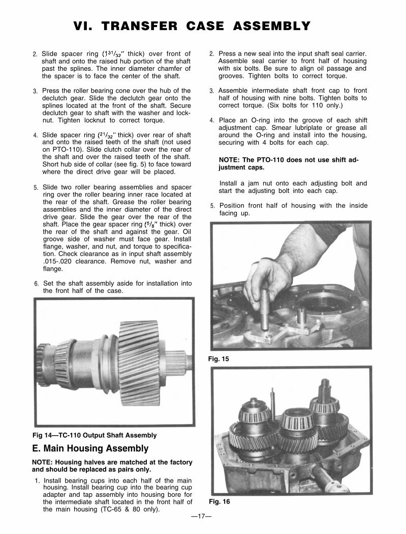
Slide two roller bearing assemblies and spacerring over the roller bearing inner race located atthe rear of the shaft. Grease the roller bearingassemblies and the inner diameter of the directdrive gear. Slide the gear over the rear of theshaft. Place the gear spacer ring (5/8” thick) overthe rear of the shaft and against the gear. Oilgroove side of washer must face gear. Installflange, washer, and nut, and torque to specifica-tion. Check clearance as in input shaft assembly.015-.020 clearance. Remove nut, washer andflange.
Set the shaft assembly aside for installation intothe front half of the case.
2.
3.
4.
5.
Press a new seal into the input shaft seal carrier.Assemble seal carrier to front half of housingwith six bolts. Be sure to align oil passage andgrooves. Tighten bolts to correct torque.
Assemble intermediate shaft front cap to fronthalf of housing with nine bolts. Tighten bolts tocorrect torque. (Six bolts for 110 only.)
Place an O-ring into the groove of each shiftadjustment cap. Smear lubriplate or grease allaround the O-ring and install into the housing,securing with 4 bolts for each cap.
NOTE: The PTO-110 does not use shift ad-justment caps.
Install a jam nut onto each adjusting bolt andstart the adjusting bolt into each cap.
Position front half of housing with the insidefacing up.
Fig. 15
Fig 14—TC-110 Output Shaft Assembly
E. Main Housing AssemblyNOTE: Housing halves are matched at the factoryand should be replaced as pairs only.
1. Install bearing cups into each half of the mainhousing. Install bearing cup into the bearing cupadapter and tap assembly into housing bore forthe intermediate shaft located in the front half of Fig. 16the main housing (TC-65 & 80 only).
—17—
VI. TRANSFER CASE ASSEMBLY
6. Reassemble the shift fork and shift shaft assem-bly if it has been disassembled. Place the propershift fork onto the clutch collar on the input andoutput shafts.
11. TC-65 only: Press seal into output shaft rear sealspeedometer gear carrier. Assemble gasket andcarrier to housing with six bolts. Be sure to align
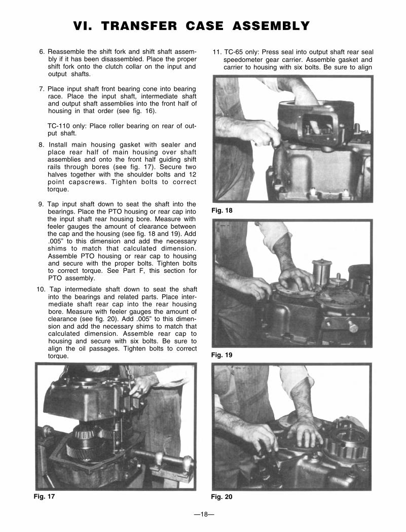
7. Place input shaft front bearing cone into bearingrace. Place the input shaft, intermediate shaftand output shaft assemblies into the front half ofhousing in that order (see fig. 16).
TC-110 only: Place roller bearing on rear of out-put shaft.
8. Install main housing gasket with sealer andplace rear half of main housing over shaftassemblies and onto the front half guiding shiftrails through bores (see fig. 17). Secure twohalves together with the shoulder bolts and 12point capscrews. Tighten bolts to correcttorque.
9. Tap input shaft down to seat the shaft into thebearings. Place the PTO housing or rear cap into Fig. 18the input shaft rear housing bore. Measure withfeeler gauges the amount of clearance betweenthe cap and the housing (see fig. 18 and 19). Add.005” to this dimension and add the necessaryshims to match that calculated dimension.Assemble PTO housing or rear cap to housingand secure with the proper bolts. Tighten boltsto correct torque. See Part F, this section forPTO assembly.
10. Tap intermediate shaft down to seat the shaftinto the bearings and related parts. Place inter-mediate shaft rear cap into the rear housingbore. Measure with feeler gauges the amount ofclearance (see fig. 20). Add .005” to this dimen-sion and add the necessary shims to match thatcalculated dimension. Assemble rear cap tohousing and secure with six bolts. Be sure toalign the oil passages. Tighten bolts to correcttorque. Fig. 19
Fig. 17 Fig. 20
—18—
VI. TRANSFER CASE ASSEMBLY
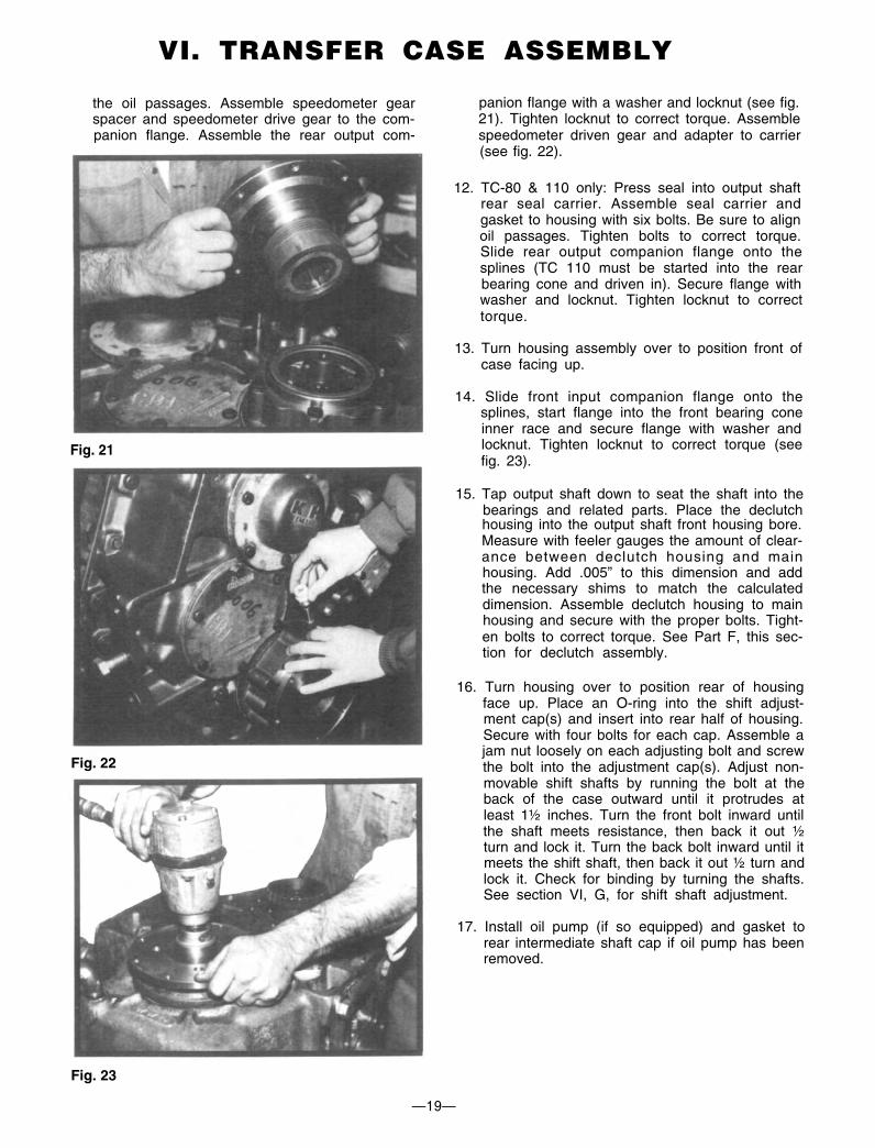
the oil passages. Assemble speedometer gearspacer and speedometer drive gear to the com-panion flange. Assemble the rear output com-
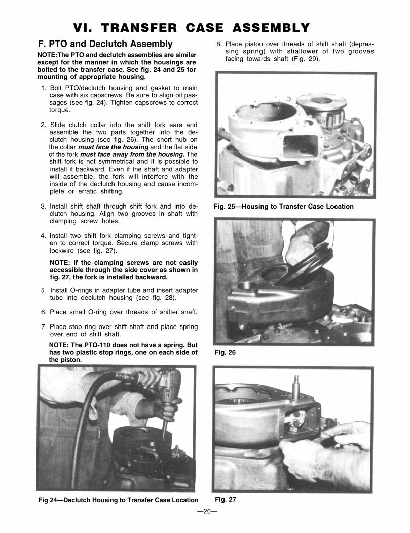
panion flange with a washer and locknut (see fig.21). Tighten locknut to correct torque. Assemblespeedometer driven gear and adapter to carrier(see fig. 22).
12. TC-80 & 110 only: Press seal into output shaftrear seal carrier. Assemble seal carrier andgasket to housing with six bolts. Be sure to alignoil passages. Tighten bolts to correct torque.Slide rear output companion flange onto thesplines (TC 110 must be started into the rearbearing cone and driven in). Secure flange withwasher and locknut. Tighten locknut to correcttorque.
13. Turn housing assembly over to position front ofcase facing up.
Fig. 21
Fig. 22
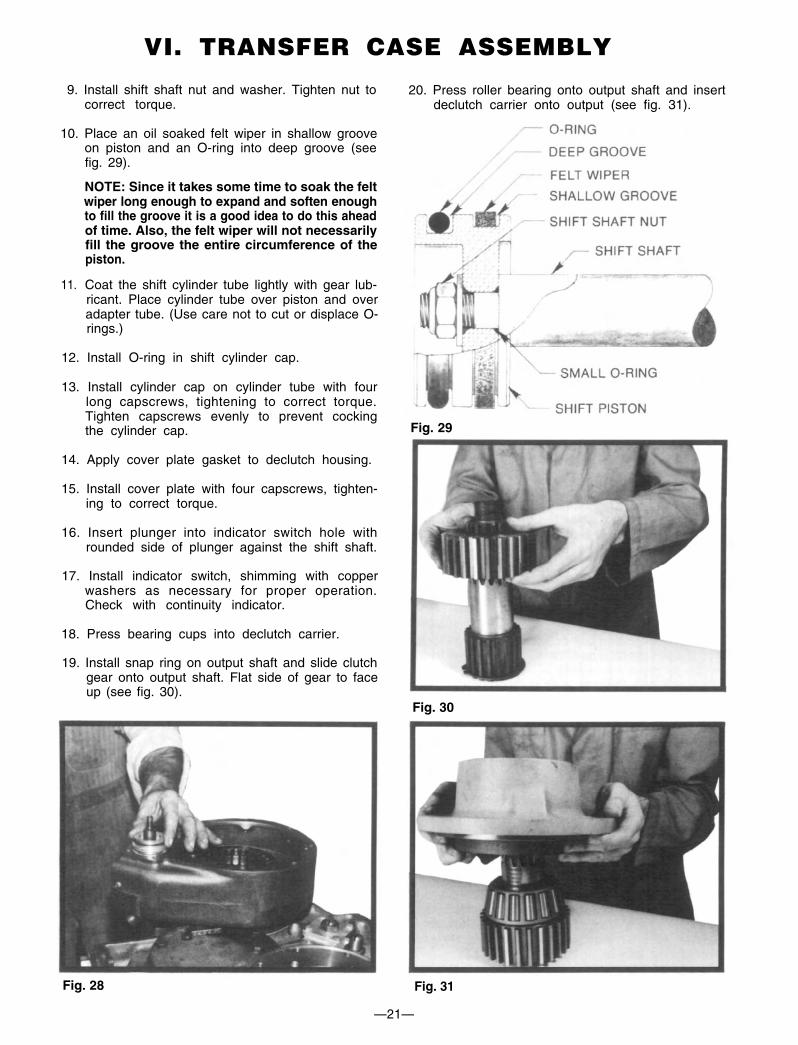
14. Slide front input companion flange onto thesplines, start flange into the front bearing coneinner race and secure flange with washer andlocknut. Tighten locknut to correct torque (seefig. 23).
15. Tap output shaft down to seat the shaft into thebearings and related parts. Place the declutchhousing into the output shaft front housing bore.Measure with feeler gauges the amount of clear-ance between declutch housing and mainhousing. Add .005” to this dimension and addthe necessary shims to match the calculateddimension. Assemble declutch housing to mainhousing and secure with the proper bolts. Tight-en bolts to correct torque. See Part F, this sec-tion for declutch assembly.
16. Turn housing over to position rear of housingface up. Place an O-ring into the shift adjust-ment cap(s) and insert into rear half of housing.Secure with four bolts for each cap. Assemble ajam nut loosely on each adjusting bolt and screwthe bolt into the adjustment cap(s). Adjust non-movable shift shafts by running the bolt at theback of the case outward until it protrudes atleast 1½ inches. Turn the front bolt inward untilthe shaft meets resistance, then back it out ½turn and lock it. Turn the back bolt inward until itmeets the shift shaft, then back it out ½ turn andlock it. Check for binding by turning the shafts.See section VI, G, for shift shaft adjustment.
17. Install oil pump (if so equipped) and gasket torear intermediate shaft cap if oil pump has beenremoved.
Fig. 23
—19—
VI. TRANSFER CASE ASSEMBLY
F. PTO and Declutch AssemblyNOTE:The PTO and declutch assemblies are similarexcept for the manner in which the housings arebolted to the transfer case. See fig. 24 and 25 formounting of appropriate housing.
1. Bolt PTO/declutch housing and gasket to maincase with six capscrews. Be sure to align oil pas-sages (see fig. 24). Tighten capscrews to correcttorque.
8. Place piston over threads of shift shaft (depres-sing spring) with shallower of two groovesfacing towards shaft (Fig. 29).
2. Slide clutch collar into the shift fork ears andassemble the two parts together into the de-clutch housing (see fig. 26). The short hub onthe collar must face the housing and the flat sideof the fork must face away from the housing. Theshift fork is not symmetrical and it is possible toinstall it backward. Even if the shaft and adapterwill assemble, the fork will interfere with theinside of the declutch housing and cause incom-plete or erratic shifting.
3. Install shift shaft through shift fork and into de-clutch housing. Align two grooves in shaft withclamping screw holes.
Fig. 25—Housing to Transfer Case Location
4. Install two shift fork clamping screws and tight-en to correct torque. Secure clamp screws withlockwire (see fig. 27).
NOTE: If the clamping screws are not easilyaccessible through the side cover as shown infig. 27, the fork is installed backward.
5. Install O-rings in adapter tube and insert adaptertube into declutch housing (see fig. 28).
6. Place small O-ring over threads of shifter shaft.
7. Place stop ring over shift shaft and place springover end of shift shaft.
NOTE: The PTO-110 does not have a spring. Buthas two plastic stop rings, one on each side ofthe piston.
Fig. 26
Fig 24—Declutch Housing to Transfer Case Location Fig. 27
—20—
VI. TRANSFER CASE ASSEMBLY
9. Install shift shaft nut and washer. Tighten nut tocorrect torque.
10. Place an oil soaked felt wiper in shallow grooveon piston and an O-ring into deep groove (seefig. 29).
20. Press roller bearing onto output shaft and insertdeclutch carrier onto output (see fig. 31).
NOTE: Since it takes some time to soak the feltwiper long enough to expand and soften enoughto fill the groove it is a good idea to do this aheadof time. Also, the felt wiper will not necessarilyfill the groove the entire circumference of thepiston.
11. Coat the shift cylinder tube lightly with gear lub-ricant. Place cylinder tube over piston and overadapter tube. (Use care not to cut or displace O-rings.)
12. Install O-ring in shift cylinder cap.
13. Install cylinder cap on cylinder tube with fourlong capscrews, tightening to correct torque.Tighten capscrews evenly to prevent cockingthe cylinder cap. Fig. 29
14. Apply cover plate gasket to declutch housing.
15. Install cover plate with four capscrews, tighten-ing to correct torque.
16. Insert plunger into indicator switch hole withrounded side of plunger against the shift shaft.
17. Install indicator switch, shimming with copperwashers as necessary for proper operation.Check with continuity indicator.
18. Press bearing cups into declutch carrier.
19. Install snap ring on output shaft and slide clutchgear onto output shaft. Flat side of gear to faceup (see fig. 30).
Fig. 30
Fig. 28 Fig. 31
—21—
VI. TRANSFER CASE ASSEMBLY

21. Place end play spacer through front of declutchcarrier and on top of inner roller bearing.
22. Press outer roller bearing onto output shaft andinto declutch carrier.
NOTE: The declutch and PTO output shaft bearingsneed no adjustment as the bearing spacer is factoryselected for proper end play. If the bearings havebeen replaced assemble the output shaft in itscarrier with output flange installed, torque theoutput flange nut to specification, and check the endplay. Use a .323 thick spacer for the first check.Experience has shown that this gives the proper endplay in 75% of assemblies the first time. If it is morethan .005 inch or less than .003 inch, substitute aspacer with another thickness and recheck. Spacersof .313, .318, .323 and .328 inch thickness are avail-able. (The PTO-110 has different bearings, and usesspacers of .360 to .385 thickness in .005 increments.)
23. Install drive flange seal with an appropriatedriver.
24. Coat the flange hub with gear lubricant. Installdrive flange onto output shaft with nut and lock-washer. Tighten nut to correct torque.
Fig. 32
25. Apply gasket to housing assembly and installdeclutch carrier with eight capscrews, tighten-ing to correct torque. Declutch carrier must beinstalled so oil seal drain passage is to thebottom of the case (see fig. 32).
G. Shift Cylinder Assembly andAdjustment
1. Screw adjusting bolt on adjustment cap locatedat input (front) side of case in until the bolt stops.
2. Install two O-rings onto shift cylinder adaptertube, coat adapter tube with gear lubricant, andinstall tube into rear of housing (see fig. 33).
Fig. 33
3. Place small O-ring over threaded end of shiftshaft and against shift shaft shoulder.
4. Place spring over end of shift shaft and intoadapter. Place plastic stop ring over spring.
NOTE: PTO-110 does not have springs, but hastwo plastic stop rings, one on each side of piston.
5. Place piston over shift shaft with the shallower ofthe two grooves toward the shaft. Make suresmall O-ring on shaft is seating in chamfer inpiston bore. Depress the spring with the pistonand secure piston with the washer and locknut.Tighten locknut to correct torque. Place an oilsoaked felt wiper in shallow groove on pistonand an O-ring in the deep groove (see fig. 34). Fig. 34
—22—
VI. TRANSFER CASE ASSEMBLY
6. Coat the shift cylinder tube lightly with lubri- I. Final Assemblycant, install cylinder tube over-piston and seatcylinder tube over O-ring in the adapter tube.Install O-ring in shift cylinder cap and installcylinder cap into the cylinder tube. Secureassembly with bolts and tighten bolts evenly toprevent misalignment of cylinder cap. Tightenbolts to correct torque.
1.
2.
Attach all mounting brackets that must besecured to the transfer case before the case canbe installed in the truck.
Install temperature sensor if vehicle is soequipped.
7. Unscrew adjusting bolt at input (front) side ofcase until approximately 1½ inches protrudefrom housing. Be sure that bolt end is not touch-ing the end of the shaft at full stroke with airapplied to the cylinder.
3 . Prior to plumbing, prime oil pump and fill filtercup with oil can.
4 . Connect oil pump lines.
8. Apply air pressure to the cylinder. Run the ad-justing bolt in until the end of the bolt makescontact with the shift shaft in the case. Turn thebolt inward ½ turn from this point and tightenthe jam nut.
5. Refer to Section III, Part B and install transfercase into vehicle.
H. Oil Pump Assembly
1. Install rotor in pump body.
2. Apply gasket(s) to cover.
3. Place idler gear on pin in cover assembly.
4. Place cover assembly with idler gear on pumphousing. Use care to align matching marks forproper location. Insure the cover notch is insame position as when removed.
5. Install cover plate capscrews securely. Pulldown gradually and alternate from a screw onone side to one on the opposite side.
6. Install and tighten housing plug with appropri-ate spanner wrench.
7. Check pump for free rotation by turning shaft(shaft should turn freely by hand without bind-ing). Rotor end play of .003-.010” can be ob-tained by adding or removing cover plategaskets.
8. Secure oil pump and gasket to rear intermediateshaft cap.
—23—
VI. TRANSFER CASE ASSEMBLY
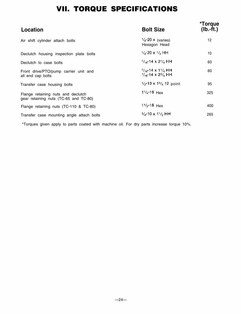
VII. TORQUE SPECIFICATIONS
Location Bolt Size
Air shift cylinder attach bolts (varies)Hexagon Head
*Torque(lb.-ft.)
12
Declutch housing inspection plate bolts
Declutch to case bolts
Front drive/PTO/pump carrier unit andall end cap bolts
Transfer case housing bolts point
Flange retaining nuts and declutch Hex
gear retaining nuts (TC-65 and TC-80)
Flange retaining nuts (TC-110 & TC-80) Hex
Transfer case mounting angle attach bolts
*Torques given apply to parts coated with machine oil. For dry parts increase torque 10%.
10
60
60
95
325
400
265
—24—