Service Bulletin 2002 American Honda Motor Co., Inc. – All Rights Reserved ATB 23043 (0209) 1 of 12 CUSTOMER INFORMATION: The information in this bulletin is intended for use only by skilled technicians who have the proper tools, equipment, and training to correctly and safely maintain your vehicle. These procedures should not be attempted by “do-it-yourselfers,” and you should not assume this bulletin applies to your vehicle, or that your vehicle has the condition described. To determine whether this information applies, contact an authorized Honda automobile dealer. September 17, 2002 02-047 Applies To: 1998–02 Passport – ALL Cylinder Head Service BACKGROUND In the 1998 through 2002 Passport Service Manuals, some of the information on cylinder head service, timing belt installation, camshaft gear timing, and valve adjustment is incomplete. For complete information, use this service bulletin along with the appropriate service manual and fuel & emissions manual. This service bulletin covers these topics: • Cylinder head removal (page 1) • Cylinder head disassembly (page 2) • Camshaft inspection (page 2) • Cylinder head installation (page 3) • Timing belt removal (page 3) • Engine timing (page 3) • Timing belt installation (page 4) • Camshaft subgear preloading, gear timing, and camshaft installation (page 5) • Valve adjustment (page 7) • Valve Inspection Chart (page 10) • Valve Shim Replacement Chart (page 11) PARTS INFORMATION NOTE: For additional parts you need, refer to the Parts Catalog. Cylinder Head Cover Gaskets: P/N 8-97170-239-1, H/C 5517909 Cylinder Head Bolts (16 required): P/N 8-97011-998-2, H/C 4396446 Valve Shims (While 41 shims are available, the 10 sizes below will cover most valve adjustments): REQUIRED SPECIAL TOOLS NOTE: For additional special tools you may need, refer to the appropriate service manual. Flange Holder: T/N 07RAB-TB4010B Holder Handle: T/N 07JAB-001020A Gear Spring Lever: T/N J-42686 Universal Holder: T/N J-43041 Valve Adjuster Holder: T/N J-42689-AH Large Binder Clip (2 required): Commercially available CYLINDER HEAD REMOVAL NOTE: Page references are to the 2002 Passport Service Manual and the 2002 Passport Fuel & Emissions Manual. 1. Remove the hood (see page 8F-15 of the service manual). 2. Disconnect the negative cable from the battery. 3. Remove the air cleaner (see page 6E2-543 of the fuel & emissions manual). 4. Remove the radiator upper fan shroud (see page 6B-8 of the service manual). 5. Remove the drive belt tensioner and the drive belt (see page 6B-11 of the service manual). 6. Remove the cooling fan assembly (4 bolts) and the cooling fan pulley. 7. Remove the power steering pump (see page 2A-23 of the service manual). 8. Drain the engine coolant (see page 6B-5 of the service manual). 9. Drain the engine oil. 10. Remove the crankshaft pulley: • Attach the flange holder (T/N 07RAB-TB4010B) with the holder handle (T/N 07JAB-001020A) to the pulley. • While holding the pulley with the tool, remove the pulley bolt and the pulley. • Install the pulley bolt. (When needed later, this will allow you to turn the crankshaft by hand.) 11. Remove the cylinder head covers (see pages 6A-19 and 6A-21 of the service manual). 12. Remove the timing belt (see TIMING BELT REMOVAL on page 3). Shim# (Size) P/N H/C 266 (2.66 mm) 8-97149-275-0 5514443 270 (2.70 mm) 8-97149-277-0 5514468 274 (2.74 mm) 8-97149-279-0 5514484 278 (2.78 mm) 8-97149-281-0 5514500 282 (2.82 mm) 8-97149-283-0 5514526 286 (2.86 mm) 8-97149-285-0 5514542 290 (2.90 mm) 8-97149-287-0 5514567 294 (2.94 mm) 8-97149-289-0 5514583 298 (2.98 mm) 8-97149-291-0 5514609 302 (3.02 mm) 8-97149-293-0 5514625
Transcript
Service Bulletin
2002 American Honda Motor Co., Inc. – All Rights Reserved ATB 23043 (0209) 1 of 12
CUSTOMER INFORMATION: The information in this bulletin is intended for use only by skilled technicians who have the proper tools, equipment,and training to correctly and safely maintain your vehicle. These procedures should not be attempted by “do-it-yourselfers,” and you should not assumethis bulletin applies to your vehicle, or that your vehicle has the condition described. To determine whether this information applies, contact anauthorized Honda automobile dealer.
September 17, 2002
02-047Applies To: 1998–02 Passport – ALL
Cylinder Head Service
BACKGROUNDIn the 1998 through 2002 Passport Service Manuals, some of the information on cylinder head service, timing belt installation, camshaft gear timing, and valve adjustment is incomplete. For complete information, use this service bulletin along with the appropriate service manual and fuel & emissions manual.This service bulletin covers these topics:• Cylinder head removal (page 1)• Cylinder head disassembly (page 2)• Camshaft inspection (page 2)• Cylinder head installation (page 3)• Timing belt removal (page 3)• Engine timing (page 3)• Timing belt installation (page 4)• Camshaft subgear preloading, gear timing, and
13. Remove the common chamber (see page 6A-22, steps 2 thru 8, of the service manual).
14. Remove the exhaust manifolds (see pages 6A-24 and 6A-25 of the service manual).
15. Remove the cylinder heads:• Loosen the head bolts in the sequence shown
below.• Remove and discard the head bolts.• Remove the cylinder heads.
CYLINDER HEAD DISASSEMBLYNOTE: • Whether you’re rebuilding a cylinder head or
assembling a new one, mark the position of each camshaft bearing cap and valve train part before you remove it. When you assemble the head, install the marked parts in their original positions.
• Service manual page references are to the 2002 Passport Service Manual.
1. Remove the camshaft drive gear, camshafts, and valve train parts, as needed, for inspection or repair (see pages 6A-48 and 6A-49 of the service manual).
2. Clean the bare head to remove all varnish, carbon, and grime.
3. Check the cylinder head and gasket, and repair the head if needed (see page 6A-49 of the service manual).
CAMSHAFT INSPECTIONNOTE: Service manual page references are to the 2002 Passport Service Manual.
1. Inspect the camshaft journal oil clearances and thrust clearances (see page 6A-62 of the service manual). If any clearances are not within specification, replace the cylinder head(s).
2. Inspect the camshaft lobe heights, journal diameters, and runout (see page 6A-61of the service manual). If any measurements are not within specification, replace the camshaft(s).
3. If any camshaft or camshaft drive gear is seized, or if the engine is seized from other mechanical causes, inspect the camshaft drive gear dowel pins and the camshaft gears.• Check the dowel pins for damage, and replace
the drive gear assemblies as needed.
• Inspect the camshaft gears for movement and correct positioning on the camshafts. If the gears are not stationary, or if their positions are incorrect, replace the camshaft(s).
DOWEL PINS
LEFT CAMSHAFTDRIVE GEAR
RIGHT CAMSHAFTDRIVE GEAR
The keyway should alignwith the top center of thefront cam lobes.
02-047 3 of 12
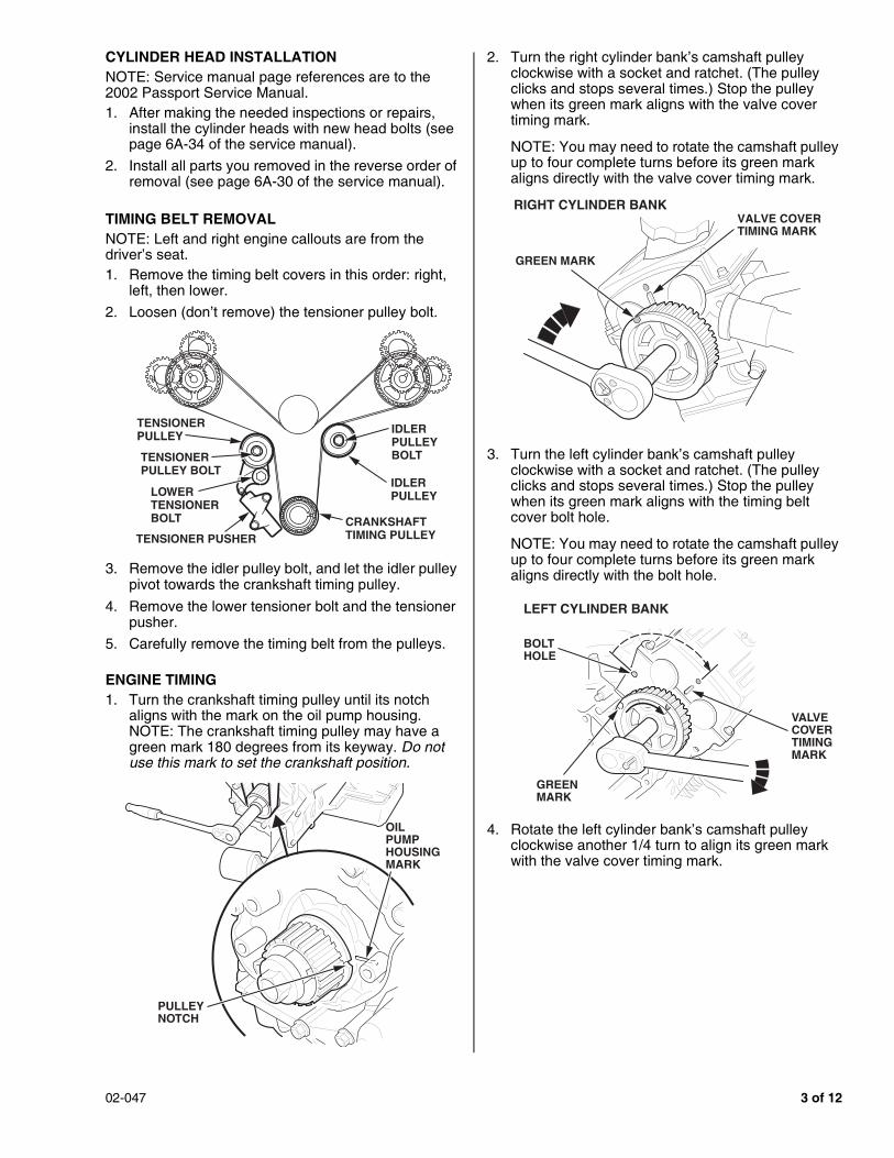
CYLINDER HEAD INSTALLATIONNOTE: Service manual page references are to the 2002 Passport Service Manual.1. After making the needed inspections or repairs,
install the cylinder heads with new head bolts (see page 6A-34 of the service manual).
2. Install all parts you removed in the reverse order of removal (see page 6A-30 of the service manual).
TIMING BELT REMOVALNOTE: Left and right engine callouts are from the driver’s seat.1. Remove the timing belt covers in this order: right,
left, then lower.2. Loosen (don’t remove) the tensioner pulley bolt.
3. Remove the idler pulley bolt, and let the idler pulley pivot towards the crankshaft timing pulley.
4. Remove the lower tensioner bolt and the tensioner pusher.
5. Carefully remove the timing belt from the pulleys.
ENGINE TIMING1. Turn the crankshaft timing pulley until its notch
aligns with the mark on the oil pump housing. NOTE: The crankshaft timing pulley may have a green mark 180 degrees from its keyway. Do not use this mark to set the crankshaft position.
2. Turn the right cylinder bank’s camshaft pulley clockwise with a socket and ratchet. (The pulley clicks and stops several times.) Stop the pulley when its green mark aligns with the valve cover timing mark.
NOTE: You may need to rotate the camshaft pulley up to four complete turns before its green mark aligns directly with the valve cover timing mark.
3. Turn the left cylinder bank’s camshaft pulley clockwise with a socket and ratchet. (The pulley clicks and stops several times.) Stop the pulley when its green mark aligns with the timing belt cover bolt hole.
NOTE: You may need to rotate the camshaft pulley up to four complete turns before its green mark aligns directly with the bolt hole.
4. Rotate the left cylinder bank’s camshaft pulley clockwise another 1/4 turn to align its green mark with the valve cover timing mark.
TENSIONERPULLEY
TENSIONER PUSHER
IDLERPULLEYLOWER
TENSIONER BOLT
TENSIONERPULLEY BOLT
IDLERPULLEYBOLT
CRANKSHAFTTIMING PULLEY
OIL PUMP HOUSINGMARK
PULLEYNOTCH
RIGHT CYLINDER BANK
GREEN MARK
VALVE COVERTIMING MARK
LEFT CYLINDER BANK
BOLTHOLE
GREENMARK
VALVECOVERTIMINGMARK
4 of 12 02-047
TIMING BELT INSTALLATIONNOTE: • Do not install the timing belt until you are sure the
camshafts, camshaft pulleys, and crankshaft timing pulley are in their correct “timed” positions.
• Left and right engine callouts are from the driver’s seat.
1. With the green direction arrows on the timing belt pointing clockwise, slip the belt over the right camshaft pulley so its solid white line (the line closest to the direction arrows) aligns with the mark on the pulley. Secure the belt to the pulley with a large binder clip.
2. Wrap the timing belt around the bottom of the water pump pulley, and draw it tight.
3. Slip the timing belt over the left camshaft pulley so its other solid white line (the one farthest from the direction arrows) aligns with the mark on the pulley. Secure the belt to the pulley with a large binder clip.
4. Wrap the timing belt around the inner side of the idler pulley, then slip the belt over the crankshaft timing pulley with its dotted white line aligned to the green mark on the crankshaft timing pulley.
NOTE: For correct belt stretch, the dotted line must meet the green mark on the crankshaft timing pulley at the 9 o’clock position. If there isn’t enough slack to slip the belt over the pulley in the correct position, turn the crankshaft a few degrees counterclockwise, install the belt, then turn the crankshaft back to the 9 o’clock position.
5. Place the tensioner pusher in a soft-jawed vise, then slowly compress the tensioner pusher pin until it lines up with the two small holes in the tensioner pusher housing.
6. Insert a straightened heavy duty paper clip through the holes in the housing. This will hold the pin in its compressed position.
NOTE: A new tensioner pusher comes with its pin held compressed by a special wire. If you install a new tensioner pusher, save the wire for future use.
BINDER CLIPSOLID WHITE LINE
BINDER CLIP SOLID WHITE LINE
GREEN MARK
CRANKSHAFT TIMING PULLEY
DOTTED WHITE LINE
TENSIONER PUSHER
HEAVY DUTYPAPER CLIP
PIN(Compressed.)
02-047 5 of 12
7. Install the tensioner pusher:• Install the lower bolt loosely.• Push the tensioner pusher up against the
tensioner pulley, then install the upper bolt, and torque it to 25 N.m (18 lb-ft).
• Torque the lower bolt to 25 N.m (18 lb-ft).
8. Remove the wire or paper clip from the tensioner pusher, and remove the binder clips from the camshaft pulleys.
9. Verify the timing belt is correctly installed: • Rotate the crankshaft three complete turns (not
two turns, as stated in the service manual).• Align the crankshaft timing pulley notch with the
mark on the oil pump housing. • Check the green marks on both camshaft
pulleys; they should line up with the valve cover timing marks.
NOTE: After you rotate the crankshaft, the solid white lines on the belt will not align with the camshaft pulley marks; this is normal.
10. Remove the crankshaft bolt, then install the lower, the right, and the left timing belt covers. Torque the cover bolts to 19 N.m (14 lb-ft).
11. Install the crankshaft pulley, and torque the bolt to 167 N.m (123 lb-ft).
12. Install any other parts you removed to replace the timing belt.
CAMSHAFT SUBGEAR PRELOADING, GEAR TIMING, AND CAMSHAFT INSTALLATIONNOTE: • The Passport V6 engine has a “non-interference”
design. This means the valves never contact the pistons, even when the valves or camshafts are not correctly timed, or even if a valve is fully open and its piston is at top dead center (TDC).
• The ratio between the camshaft drive gear and the camshaft gears is 1.33 to 1. This means the timing dots on a correctly timed camshaft will only align with the dots on the camshaft drive gears every 4th turn of the camshaft pulley.
• The left and right intake camshafts are different. On the cam lobe side of the camshaft gear, the left intake camshaft is marked “LI,” and it has dual timing dots; the right intake camshaft is marked “RI,” and it has a single timing dot.
• The left and right exhaust camshafts are the same. On the cam lobe side of the camshaft gear, both camshafts are marked “LE” and “RE,” and both have dual timing dots and a single dot.
• Service manual page references are to the 2002 Passport Service Manual.
1. Before you install the camshafts, preload the subgears (preloading must be done whenever you remove the bearing caps from a camshaft): • Make sure the spring is installed between the
camshaft gear and the subgear.• With the camshaft held in a soft-jawed vise,
attach the gear spring lever (T/N J-42686) to the subgear, then turn the subgear until its threaded hole lines up with the hole in the camshaft gear.
• Lock the subgear to the camshaft gear with a5 x 0.8 mm bolt through either side of the gear hole.
• Preload the subgears on the other camshafts.
TENSIONERPULLEY
TENSIONERPUSHER
LOWER BOLT
UPPER BOLT
PULLEY MARKS
CRANKSHAFTTIMING PULLEY OIL PUMP
HOUSING MARK
CAMSHAFTPULLEYS
PULLEY NOTCH
GEAR SPRINGLEVERCAMSHAFT GEAR
VISE
SUBGEAR
BOLT(Either side.)
6 of 12 02-047
2. On the right cylinder bank, turn the camshaft pulley until its green mark is at 12 o’clock in relation to the head surface, at the center of the head. Turning the pulley brings the timing dots on the camshaft drive gear into their correct position: to the left and right of the gear’s centerline.
3. On the left cylinder bank, turn the camshaft pulley until its green mark is at 12 o’clock in relation to the head surface, at the center of the head. Then turn the pulley counterclockwise until its green mark points close to the timing belt cover bolt hole. Turning the pulley brings the timing dots on the camshaft drive gear into their correct position: to the left and right of the gear’s centerline.
4. Install the intake and exhaust camshafts in the right cylinder bank:• Set the camshaft marked “RI” into the intake side
of the head. Make sure the single timing dot on the camshaft gear aligns with the timing dot on the camshaft drive gear.
• Set the camshaft marked “RE” and “LE,” into the exhaust side of the cylinder bank, with “RE” at the 12 o’clock position. Make sure the single timing dot on the camshaft gear aligns with the timing dot on the camshaft drive gear.
5. Install the left cylinder bank intake and exhaust camshafts:• Set the camshaft marked “LI” into the intake side
of the head. Make sure the dual timing dots on the camshaft gear align with the timing dot on the camshaft drive gear.
• Set the camshaft marked “LE” and “RE,” into the exhaust side of the cylinder bank, with “LE” at the 12 o’clock position. Make sure the dual timing dots on the camshaft gear align with the timing dot on the camshaft drive gear.
RIGHT CYLINDER BANK
GREEN MARK
VALVE COVERTIMING MARK
CENTERLINE
TIMINGDOTS
INTAKE SIDE EXHAUST SIDE
12 o'clock(At center of head.)
RIGHT CAMSHAFTDRIVE GEAR
LEFT CYLINDER BANK
BOLTHOLE
GREENMARK
VALVECOVERTIMINGMARK
CENTERLINE
TIMINGDOTS
EXHAUST SIDE INTAKE SIDE
BOLT HOLE
12 o'clock(At center of head.)
LEFT CAMSHAFTDRIVE GEAR
RIGHT BANK(Cylinders 1, 3, and 5)
SINGLETIMING DOTS
RIRIGHT INTAKECAMSHAFT GEAR
RIGHT CAMSHAFTDRIVE GEAR
RERIGHT EXHAUSTCAMSHAFT GEAR
LEFT BANK
DUALTIMINGDOTS
LELEFT EXHAUSTCAMSHAFT GEAR
LILEFT INTAKECAMSHAFT GEAR
LEFT CAMSHAFTDRIVE GEAR
02-047 7 of 12
6. Install the camshaft bearing caps in the same locations and directions they were before you removed them. NOTE: On the right cylinder bank, the directional arrows on the bearing caps should point towards the front of the engine. On the left bank, the arrows should point towards the rear of the engine.
7. Install the bearing cap bolts, then torque them to 10 N.m (7 lb-ft) in the sequence shown below.
8. Remove the bolts used to hold the preload of the camshaft subgears.
9. If not already done, inspect the camshaft thrust clearances (see page 6A-62 of the service manual). If any clearances are not within specification, replace the cylinder head(s).
VALVE ADJUSTMENTNOTE: • Valve adjustment can be done either on-vehicle or
off-vehicle.• To measure exhaust valves, you need a 0.25 mm
and a 0.35 mm feeler gauge.• To measure intake valves, you need a 0.23 mm and
a 0.33 mm feeler gauge. Since these are odd sizes, you may need to stack two gauges (for example, 0.11 mm and 0.12 mm to make 0.23 mm). If you do this, make sure the gauges are clean and in good condition. If you’re not sure the gauge stack is correct, measure it with a micrometer.
• Service manual page references are to the 2002 Passport Service Manual.
On-Vehicle Valve Adjustment1. Make a copy of the Valve Inspection Chart on
page 11.
2. Make a copy of the Valve Shim Replacement Chart on pages 12 and 13, then tape the pages together, side-by-side.
3. Remove the cylinder head covers (see pages 6A-19 and 6A-21 of the service manual).
4. Measure the valve clearances using the Go/No-Go method (see the note below). The clearances must be • Intake valves: 0.28 mm ± 0.05 mm• Exhaust valves: 0.30 mm ± 0.05 mm
NOTE: • To measure with the Go/No-Go method, use two
feeler gauges, one to measure the smallest allowable clearance, and the other to measure the largest. - If the small gauge fits and the large gauge
doesn’t, the valve adjustment is OK.- If the small gauge doesn’t fit, or if the large
gauge slides easily, the valve needs adjustment.
• The feeler gauges slide through the clearance gap at a slight angle, making the drag a little more than it would be on other engines.
5. For valves with the correct clearance, draw an “X” in the appropriate circle on the Valve Inspection Chart. For valves with incorrect clearances, write down the clearance you measured in the circle.
6. If you need to replace a valve shim, turn the crankshaft (or camshaft) until the cam lobe for the valve points away from the valve.
INTAKE
EXHAUST
EX IN#1
VALVE INSPECTION CHARTExample for #1 Cylinder
In this example, the clearance of the frontexhaust valve is incorrect (0.37 mm).The clearance of the other three valves is OK.
0.37mm
8 of 12 02-047
7. Turn the valve tappet with a pick or a small screwdriver until the tappet notch is within the indentation in the head.
8. Turn the crankshaft (or camshaft) pulley clockwise until the cam lobe presses the valve fully open.
9. On the tappet side closest to the bearing cap, insert the valve adjuster holder (T/N J-42689-AH) between the camshaft and the tappet. The tool should rest on the edge of the tappet without touching the shim.
10. Slowly turn the crankshaft (or camshaft) pulley counterclockwise so that when the valve closes, the tool catches between the camshaft and the tappet, holding the valve slightly open.
NOTE: Do not turn the crankshaft (or camshaft) pulley too far or in the wrong direction. If you do, you might break the tool, or worse yet, damage the cylinder head.
11. Insert a pick or a small screwdriver into the tappet notch, and pry out the shim.
12. Wipe off the shim, then write its number on the Valve Inspection Chart for that valve and cylinder. If there is no number on the shim, measure its thickness with a micrometer, and write down the measurement on the Valve Inspection Chart.
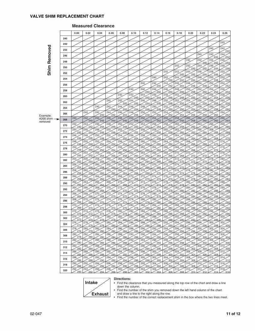
13. Follow the directions on the Valve Shim Replacement Chart to select the correct shim.
14. Insert the correct shim, number side down, into the tappet. Make sure the shim is fully seated.
15. Release and remove the tool by turning the crankshaft (or camshaft) pulley clockwise.
16. Turn the crankshaft (or camshaft) pulley clockwise until the cam lobe again points away from the valve.
17. Recheck the valve clearance using the Go/No-Go method (see step 4).• If the clearance is OK, repeat steps 6 thru 17 for
the other valves needing adjustment.• If the clearance is still incorrect, repeat steps 6
through 17 until it is correct, then adjust the remaining valves.
18. Turn the camshaft pulleys until the single timing dot (right cylinder bank) and dual timing dots (left cylinder bank) align with the single timing dots on the camshaft drive gears.
19. Install the cylinder head covers with new gaskets (see pages 6A-20 and 6A-21). Torque the cover bolts to 9 N.m (6.5 lb-ft).
Off-Vehicle Valve Adjustment1. Make a copy of the Valve Inspection Chart on
page 11.
2. Make a copy of the Valve Shim Replacement Chart on pages 12 and 13, then tape the pages together, side-by-side.
3. Measure the valve clearances using the Go/No-Go method (see the note below). The clearances must be • Intake valves: 0.28 mm ± 0.05 mm• Exhaust valves: 0.30 mm ± 0.05 mm
NOTE: • To measure with the Go/No-Go method, use two
feeler gauges, one to measure the smallest allowable clearance, and the other to measure the largest. - If the small gauge fits and the large gauge
doesn’t, the valve adjustment is OK. - If the small gauge doesn’t fit, or if the large
gauge slides easily, the valve needs adjustment.
• The feeler gauges slide through the clearance gap at a slight angle, making the drag a little more than it would be on other engines.
TAPPET NOTCH
INDENTATION
VALVEADJUSTERHOLDER(Rotate into placebetween tappetand camshaft.)
Cam lobe down.
SHIM(Number sidefaces down.)
02-047 9 of 12
4. For valves with the correct clearance, draw an “X” in the appropriate circle on the Valve Inspection Chart. For valves with incorrect clearances, write down the clearance you measured in the circle.
5. Rotate the camshaft pulley until the dual timing dots (exhaust camshaft) and single timing dot (intake camshaft) align with the timing dots on the camshaft drive gear.
6. Lock the camshaft gear to its subgear with a5 x 0.8 mm bolt through either side of the hole in the gears. This holds the spring-loaded subgear in place so you can remove the camshaft. Do this for each camshaft you need to remove.
7. Remove the camshaft bearing caps, noting the location and direction of each cap.
8. Remove the camshaft(s).
9. For each valve needing adjustment, do steps 10 thru 13.
10. Insert a pick or a small screwdriver into the tappet notch, and pry out the shim.
11. Wipe off the shim, then write its number on the Valve Inspection Chart for that valve and cylinder. If there is no number on the shim, measure its thickness with a micrometer, and write down the measurement on the Valve Inspection Chart.
12. Follow the directions on the Valve Shim Replacement Chart to select the correct shim.
13. Insert the correct shim, number side down, into the tappet. Make sure the shim is fully seated.
14. Install the camshafts (see steps 2 thru 9 of CAMSHAFT SUBGEAR PRELOADING, GEAR TIMING, AND CAMSHAFT INSTALLATION).
15. Rotate the camshaft pulleys a few turns to ensure the new shims are fully seated.
16. Recheck the clearances of the valves you adjusted with the Go/No-Go method (see step 3). If any clearances are incorrect, readjust them.
EX IN#1
VALVE INSPECTION CHARTExample for #1 Cylinder
In this example, the clearance of the frontexhaust valve is incorrect (0.37 mm).The clearance of the other three valves is OK.
0.37mm
DUAL TIMING DOTS
Insert bolt here.
LEFT CAMSHAFTDRIVE GEAR
LILEFT INTAKECAMSHAFT GEAR
LELEFT EXHAUSTCAMSHAFT GEAR
SINGLE TIMING DOTS
Insert bolt here.
RIGHT CAMSHAFTDRIVE GEAR
RERIGHT EXHAUSTCAMSHAFT GEAR
RIRIGHT INTAKECAMSHAFT GEAR
SHIM(Number sidefaces down.)
10 of 12 02-047
VALVE INSPECTION CHART
FRONT OF ENGINE
Directions: Check the clearance of each valve (12 intake and 12 exhaust). If a valve’s clearance is correct, draw an “X” in the circle that represents that valve. If its clearance is incorrect, measure the actual clearance, and write the number in the circle for that valve.NOTE: Left and right cylinder bank designations are from the driver’s seat.
EX IN#5
EX IN#3
EX IN#1
IN EX#6
IN EX#4
IN EX#2
Right Cylinder Bank Left Cylinder Bank
02-047 11 of 12
VALVE SHIM REPLACEMENT CHART
Directions:• Find the clearance that you measured along the top row of the chart and draw a line
down the column.• Find the number of the shim you removed down the left hand column of the chart
and draw a line to the right along the row.• Find the number of the correct replacement shim in the box where the two lines meet.