Skyjack Corporation USA 3451 Swenson Ave St. Charles IL 60174 USA INDUSTRIAL GROUP Tel: 630 2622 0005 Fax: 630 262 0006 linamar.com skyjack.com A Division of Linamar Holdings Inc. Service Bulletin #111 SJ 61T/SJ 66T Extension Cylinder Wear Pad Replacement December 30, 2009 Models Affected: SJ 61T, SJ 66T SJ 61T 97000002, 97000003, 97000016, 97000017, 97000067 to 97000094, 97000096 to 97000107, 97000119, 97000124, 97000141, 97000142, 97000146, 97000152 SJ 66T 97000001, 97000004 to 97000015, 97000018 to 97000066, 97000095, 97000108 to 97000118, 97000120 to 97000123, 97000125 to 97000140, 97000143 to 97000145, 97000147 to 97000151, 97000153 to 97000157 Introduction: In our continuing effort to provide the best possible product to our customers and yours, we request that the following extension cylinder wear pad replacement be completed for all machines listed above. Failure to implement this bulletin can potentially result in permanent deformations in the boom structure under certain conditions. Procedure: All units within the above serial number ranges should be inspected and repaired as specified in the attached procedure. Parts and Warranty Policy: Skyjack will allow up to 4 hours of labor per machine to complete this bulletin, and up to 2 hours of travel. Skyjack requires that this bulletin be performed before December 30, 2010, or future structural warranties may be void. Request the necessary parts to complete this bulletin by using attached part request form.
Transcript
Skyjack Corporation USA 3451 Swenson Ave St. Charles IL 60174 USA INDUSTRIAL GROUPTel: 630 2622 0005 Fax: 630 262 0006 linamar.com skyjack.com A D i v i s i o n o f L i n a m a r H o l d i n g s I n c .
Service Bulletin #111 SJ 61T/SJ 66T
Extension Cylinder Wear Pad Replacement
December 30, 2009 Models Affected: SJ 61T, SJ 66T SJ 61T 97000002, 97000003, 97000016, 97000017, 97000067 to 97000094, 97000096 to 97000107, 97000119, 97000124, 97000141, 97000142, 97000146, 97000152 SJ 66T 97000001, 97000004 to 97000015, 97000018 to 97000066, 97000095, 97000108 to 97000118, 97000120 to 97000123, 97000125 to 97000140, 97000143 to 97000145, 97000147 to 97000151, 97000153 to 97000157 Introduction: In our continuing effort to provide the best possible product to our customers and yours, we request that the following extension cylinder wear pad replacement be completed for all machines listed above. Failure to implement this bulletin can potentially result in permanent deformations in the boom structure under certain conditions. Procedure: All units within the above serial number ranges should be inspected and repaired as specified in the attached procedure. Parts and Warranty Policy: Skyjack will allow up to 4 hours of labor per machine to complete this bulletin, and up to 2 hours of travel. Skyjack requires that this bulletin be performed before December 30, 2010, or future structural warranties may be void. Request the necessary parts to complete this bulletin by using attached part request form.
Skyjack Corporation USA 3451 Swenson Ave St. Charles IL 60174 USA INDUSTRIAL GROUPTel: 630 2622 0005 Fax: 630 262 0006 linamar.com skyjack.com A D i v i s i o n o f L i n a m a r H o l d i n g s I n c .
Upon completion of this service bulletin, please submit a warranty claim form for each machine stating that Service Bulletin #111 has been completed. Ownership of Machines: If you have sold or transferred a machine(s) with the serial numbers listed above, it is your responsibility to forward this service bulletin to the current owner and to notify Skyjack Inc. Contact Information: We regret the inconvenience and appreciate your cooperation. If you have any questions please call Skyjack at 1-800-275-9522. You may e-mail any questions to [email protected]
Skyjack Corporation USA 3451 Swenson Ave St. Charles IL 60174 USA INDUSTRIAL GROUPTel: 630 2622 0005 Fax: 630 262 0006 linamar.com skyjack.com A D i v i s i o n o f L i n a m a r H o l d i n g s I n c .
Service Bulletin #111 Parts Kit Shipment Request Form
Customer Name: ____________________ PO#: _______________________ Customer Location: ______________________________________________ Address: __________________________ Phone: ______________________ City: ______________________________ Fax: _________________________ State: _______ Zip:__________ Contact Name: ________________________ We are requesting parts kit shipment for the following machines to comply with Service Bulletin #111. Please fill in the serial numbers of units in your possession that require a parts kit shipment for this bulletin to be completed.
Machine Serial Number Machine Serial Number Machine Serial Number
Please Fax This Form To: Skyjack Service Fax: (630) 262-0006 or 44-1691-676-238 (Europe)
If you have any questions please call Skyjack Service at 800-275-9522, 630-262-0005 or 44-1691-676-235 (Europe). You can e-mail any questions to [email protected] If you have sold or transferred a machine(s) with the serial numbers listed above, it is your responsibility to forward this service bulletin to the current owner and to notify Skyjack Inc.
Skyjack Corporation USA 3451 Swenson Ave St. Charles IL 60174 USA INDUSTRIAL GROUPTel: 630 2622 0005 Fax: 630 262 0006 linamar.com skyjack.com A D i v i s i o n o f L i n a m a r H o l d i n g s I n c .
This page intentionally left Blank.
Boom Arm AssemblyRetrofit Instruction155091AC
TM
Part # 155091AC
ModelSJ 61T / 66T
Boom Arm Assembly- Retrofit Instruction
SKYJACK, Page 2 Boom Arm AssemblyRetrofit Instruction
155091AC
WARNING
Only trained and authorized personnel shall be permitted to service an aerial platform.
WARNING
Read all instructions closely before attempting eachstep of the procedure.
WARNING
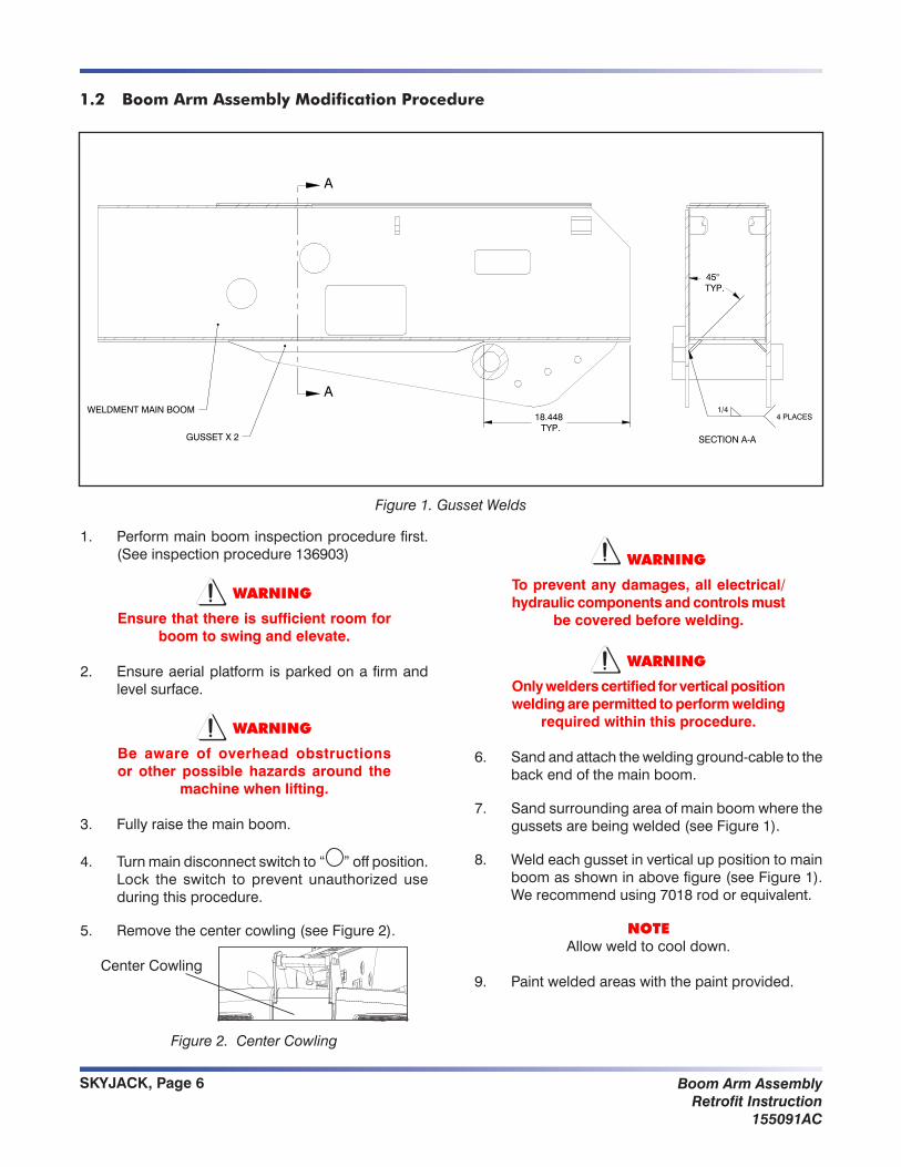
Only welders certified for vertical position welding are permitted to perform welding required within this procedure.
WARNING
To prevent any damage, all electrical and control components must be covered before welding.
NOTE
If you have not received the complete part inventory, contact the SKYJACK Service Department at:
North America & Asia: Europe:( : 800 275-9522 ( : 44-1691-676-2357 : 630 262-0006 7 : 44-1691-676-238
Do not attempt installation without the complete package.
SKYJACK, Page 3Boom Arm AssemblyRetrofit Instruction155091AC
Table of Contents
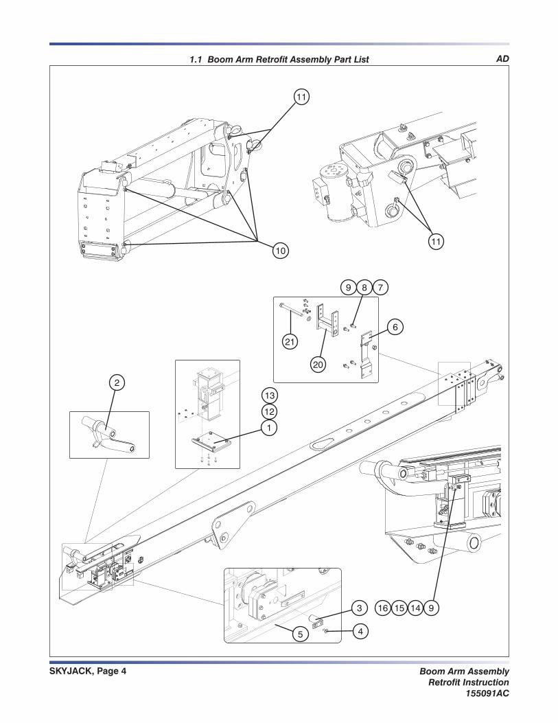
1.1 Boom Arm Retrofit Assembly Part List ...................................................................................................41.2 Boom Arm Assembly Modification Procedure ......................................................................................61.3 Pulley Pin Replacement .........................................................................................................................81.4 Power Track Carrier Modifications .......................................................................................................101.5 Basket Stopper Modification ................................................................................................................111.6 Boom Modifications .............................................................................................................................121.7 Test Procedure .....................................................................................................................................12
SKYJACK, Page 7Boom Arm AssemblyRetrofit Instruction155091AC
Unlockandturnmainpowerdisconnectswitch10. to “ ”onposition.
Lower the main boom to horizontal position and 11. ensure boom is fully retracted to align flanges withboomholes(seeFigure3).
Figure 3. Flanges Aligned to Boom Holes
Turn main disconnect switch to “12. ”offpositionand lock the switch.
Disconnect thehoses fromextensioncylinder,13. and then remove the hoses from hose bracket (seeFigure4).
Support the link weldment, and then remove pin 14. #1fromturret(seeFigure4)andsetitasideforreuse.
LinkWeldmentPin#1
HoseBracket
Figure 4. Main Boom - Turret End
Remove pin #2 from cylinder support and 15. discard(seeFigure5).
LinkWeldmentPin #2
Figure 5. Link Weldment Pin #2 at Rod End
Carefully remove the link weldment.16.
Reconnectthehosestoextensioncylinder.17.
Unlockandturnmainpowerdisconnectswitch18. to “ ”onposition.
With the assistance of a colleague; carefully19. activatetheextendflyboomswitchandlifttheboomuntilextensioncylindersupportisentirelyoutside of the back of the boom.
Turn main disconnect switch to “20. ”offpositionand lock the switch.
SKYJACK, Page 8 Boom Arm AssemblyRetrofit Instruction
155091AC
Unlockandturnmainpowerdisconnectswitch23. to “ ”onposition.
With the assistance of a colleague; carefully24. activate the retract fly boom switch and lower the boomuntilextensioncylinderarrivesatpreviouslocation inside the boom.
Turn main disconnect switch to “25. ”offpositionand lock the switch.
Disconnectthehosesfromextensioncylinder.26.
Install the new link weldment to turret and 27. extensioncylindersupport(seeFigure8).
NOTEUseloctite#242andthentorquethebolts
to 35 lb-ft.
NewLinkWeldment
HoseBracket
Figure 8. New Link Weldment
Reroute the hoses through link weldment hose 28. bracket(seeFigure8).
Reconnectthehosestoextensioncylinder.29.
Locate the bottom plate inside the boom where 30. extension cylinder support travels (seeFigure9).
Bottom Plate
Figure 9. Bottom Plate
Sand and clean the entire inside bottom boom 31. plate.
Paint the sanded surface with the paint provided 32. (seeFigure9).
CheckclearanceonwearpadsshowninFigure9.33. Add shims if needed.
NOTEPlease refer to the service manual for wear
pad clearance information.
CAUTION
Allow paint to dry fully before any operation.
1.3 Pulley Pin Replacement
If the aerial platform is equipped with new style 1. of pulley pin (see Figure 10), disregard thisreplacement procedure.
OldPulleyPin
NewPulley Pin
701620
Figure 10. Pulley Pins
If the aerial platform is equipped with old style 2. ofpulleypin (see figure10),proceedwith thefollowing steps.
CAUTION
Do not use any type of power tools for pulley pin replacement
CheckWearPad Clearance
SKYJACK, Page 9Boom Arm AssemblyRetrofit Instruction155091AC
Locate the two lower cable anchor points at boom 3. end(seeFigure11).
OuterandInner nuts
Left- Side Cable
Right-Side Cable
Figure 11. Lower Cable Anchor Points
CAUTION
Change one pin at a time
For the right-side cable only:
Remove the outer nut and loosen the inner nut 4. to the end of thread, and then push the cable into the boom.
Carefully remove the pulley pin.5.
Install the new style pulley pin provided in your 6. kit(seeFigure12).
NewPulley Pin701620
Figure 12. Pulley Pins
NOTEUseloctite#242andthentorquethebolts
to 23 lb-ft.
Tighten the Cables:
NOTEDo not position all disk spring in one
direction(SeeFigure13).
Figure 13. Disc Spring Setup
Tighten inner nut until no gaps are shown in 7. betweensprings(seeFigure14).
WithGaps
InnerNut
OuterNut
Disk Spring
NoGaps
Figure 14. Cable End Configuration
Tighten same nut an additional half a turn.8.
For the left-side cable only:
Repeat step 4 to 8 for the left-side cable.9.
Unlockandturnmainpowerdisconnectswitch10. to “ ”onposition.
Cycle boom through one full extension and11. retraction, then one full raise and lower.
Lower the main boom to horizontal position and 12. ensure boom is fully retracted
Turn main disconnect switch to “13. ”offpositionand lock the switch.
Inspect the disk springs for gaps.14.
If necessary, repeat step 7 and 8 if gaps are 15. shown.
Install and tighten outer nuts to secure inner nuts 16. for both cables.
SKYJACK, Page 10 Boom Arm AssemblyRetrofit Instruction
155091AC
1.4 Power Track Carrier Modifications
Unlockandturnmainpowerdisconnectswitch1. to “ ”onposition.
Lower the main boom to a suitable working 2. height.
Turn main disconnect switch to “3. ”offpositionand lock the switch.
Install the front wear pads and cover (see11. Figure19).
Bottom WearPad
Top Wearpad
Figure 19. Proper Wear Pad Orientation
New6.25”FrontWearPadSupport 8”Front
SupportBolt
SKYJACK, Page 11Boom Arm AssemblyRetrofit Instruction155091AC
Fully tighten all bolts, for proper torque12. specification(seeFigure20).
Torque to 280 lb-ft
Torque to 23 lb-ft
Torque to 75 lb-in
Figure 20. Proper Torque Specification
Check boom wear pad clearance as shown in 13. Figure21.
NOTEPlease refer to the service manual for wear pad maintenance procedure and
clearance information.
1.5 Basket Stopper Modification
Lower/raisetheboomtovariouspositions.Rotate1. the basket counter clockwise until the platform kickplateisabouttointerferewiththeE-chainbracket support bolt. Throughout the range of motion, if stopper (Figure 21)didnot preventinterference, proceed with modification.
Build the stopper surface with weld to ensure the 2. minimum distance between the basket and the E-chainbracketsupportbolttobe1/2”.
Figure 21. Basket Interference
Grind thewelded surface flat to ensure even3. stopper contact with the platform support.
Figure 22. Stopper Modification
Build with weld on this surface to the required thickness
Stopper
Measure the gap
Check for interference
Bottom view
E-chainbracketsupport bolt
Platform kick plate
Platform support
Check Clearance
Check Clearance
SKYJACK, Page 12 Boom Arm AssemblyRetrofit Instruction
155091AC
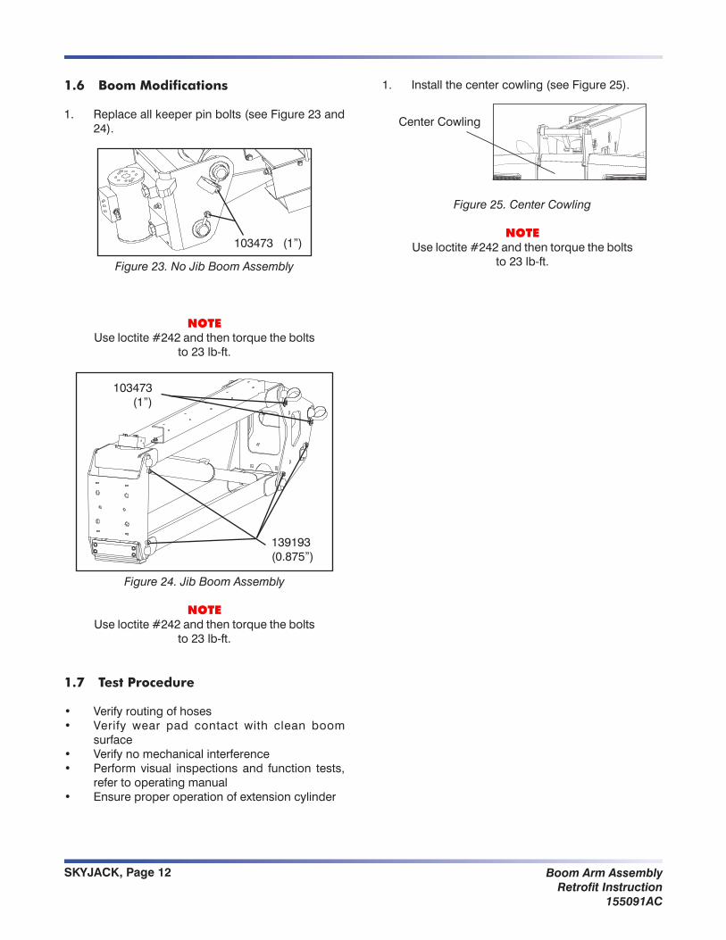
1.6 Boom Modifications
Replaceallkeeperpinbolts(seeFigure23and1. 24).
103473(1”)
Figure 23. No Jib Boom Assembly
NOTEUseloctite#242andthentorquethebolts
to 23 lb-ft.
139193 (0.875”)
103473(1”)
Figure 24. Jib Boom Assembly
NOTEUseloctite#242andthentorquethebolts
to 23 lb-ft.
1.7 Test Procedure
Verify routing of hoses•Verify wear pad contact with clean boom •surfaceVerify no mechanical interference •Perform visual inspections and function tests, •refer to operating manualEnsureproperoperationofextensioncylinder•
Installthecentercowling(seeFigure25).1.
Center Cowling
Figure 25. Center Cowling
NOTEUseloctite#242andthentorquethebolts
to 23 lb-ft.
SKYJACK, Page 13Boom Arm AssemblyRetrofit Instruction155091AC
Table 1.1 Torque Values Corresponding to Fastener Load