NOTICE: This service data sheet is intended for use by persons having electrical and me- chanical training and a level of knowledge of these subjects generally considered acceptable in the appliance repair trade. The manufacturer cannot be responsible, nor assume any liability, for injury or damage of any kind arising from the use of this data sheet. IMPORTANT NOTE: This unit includes an EOC (electronic oven control). This board is not field-repairable. Safe Servicing Practices To avoid the possibility of personal injury and/or property damage, it is important that safe ser- vicing practices be observed. The following are some, but not all, examples of safe practices. 1. Do not attempt a product repair if you have any doubts as to your ability to complete it in a safe and satisfactory manner. 2. Before servicing or moving an appliance, remove power cord from electric outlet, trip circuit breaker to Off, or remove fuse. 3. Never interfere with the proper installation of any safety device. 4. Use only replacement parts specified for this appliance. Substitutions may not comply with safety standards set for home appliances. 5. Grounding: The standard color coding for safety ground wires is green or green with yellow stripes. Ground leads are not to be used as current carrying conductors. It is extremely important that the service technician reestablish all safety grounds prior to completion of service. Failure to do so will create a potential hazard. 6. Prior to returning the product to service, ensure that: • All electric connections are correct and secure. • All electrical leads are properly dressed and secured away from sharp edges, high-temperature components, and moving parts. • All uninsulated electrical terminals, connectors, heaters, etc. are adequately spaced away from all metal parts and panels. • All safety grounds (both internal and external) are correctly and securely reas- sembled. • All panels are properly and securely reassembled. IMPORTANT DO NOT REMOVE THIS BAG OR DESTROY THE CONTENTS WIRING DIAGRAMS AND SERVICE INFORMATION ENCLOSED REPLACE CONTENTS IN BAG p/n 807880709 EN (Rev A 15/04) ELECTRONIC OVEN CONTROL (EOC) FAULT CODE DESCRIPTIONS Note: Generally speaking “F1X” implies a control failure, “F3X” an oven probe problem, and “F9X” a latch motor problem. Code Condition/Cause Suggested Corrective Action F10 Control has sensed a potential runaway oven condition. Control may have shorted relay, RTD sensor probe may have a gone bad. Check RTD sensor probe and replace if necessary. If oven is overheating, disconnect power. If oven continues to overheat when power is reapplied, replace relay board and/or display board. F11 Shorted Key: a key has been detected as pressed for a long period and will be considered a shorted key alarm and will terminate all oven activity. 1. Press any key to clear the error. 2. If fault returns, replace the keyboard (touch panel). 3. If the problem persists, replace the display board. F13 Control's internal checksum may have become corrupted. 1. Press any key to clear the error. 2. Disconnect power, wait 30 seconds and reapply power. If fault returns upon power-up, replace display board. F14 Misconnected keyboard cable 1. Verify connection between display board and touch panel (2 ribbon cables). Make sure the cables are well connected at both ends. 2. If the cables are good, replace the touch panel. 3. If the problem persists, replace the display board. F15 Controller self check failed. 1. Verify if relay board receives 120VAC between J4 pin 1 and 3. 2. Verify the wiring between J2 on the relay board and P16 on the display board. 3. If wiring and 120VAC supply is good replace the display board. 4. If problem persists replace the relay board. F20 The oven controller has detected a problem with the communication link to the surface element controller (ESEC). 1. Is the ESEC User Interface Board powered on (are the surface element displays showing something)? If not, that is the reason why the oven control cannot communicate with it (ESEC has no power). Check the 120VAC voltage going in to the ESEC power supply board located in the front console (connector P1) and the low voltage supply going from the power supply board (connector P2) to the ESEC UIB (connector P8). 2. Check connections between connector P2 on the oven controller and P9 on the ESEC UIB. This is the communication link. Verify for continuity. Refer to the wiring diagram. 3. If the above steps failed to solve the problem, replace the ESEC UIB. 4. If problem persists replace the oven controller. F23 The controller failed to communicate with the oven lights control board. 1. Verify wiring between P2 on the display board and P2 on the oven lights control board. 2. If wiring is good, replace oven lights board. 3. If the problem persists, replace the display board. F30 Open RTD sensor probe/ wiring problem. Note: EOC may initially display an “F10”, thinking a runaway condition exists. 1. Check wiring in probe circuit for possible open condition. 2. Check RTD resistance at room temperature (compare to probe resistance chart). If resistance does not match the chart, replace the RTD sensor probe. 3. Let the oven cool down and restart the function. 4. If the problem persists, replace the display board. Note: F30 or F31 is displayed when oven is in active mode or an attempt to enter an active mode is made. F31 Shorted RTD sensor probe / wiring problem. F43 The cooling fan speed, as read by the tachometer input of the EOC-display board, is abnormally too slow. 1. Determine first if the problem appears to be caused by a cooling fan not turning or turning slowly or by a problem with the sensing of the fan speed. Start a Bake and check during the first 15 seconds if the fan is turning (should feel air flowing through the vent above the upper oven door). 2. If the fan does not appear to be turning or turn slowly check the 120VAC at the fan. If 120VAC is present at the fan motor but the fan does not turn replace the fan motor. If 120VAC is not present at the fan motor when a Bake is started check the connection to the relay board (J3 pin 7) and Neutral: is there 120VAC on J3 pin 7? Does it reach the fan motor? Is the other terminal of the fan motor connected to Neutral? If the harness or relay board are faulty replace them. 3. If the fan appears to be normally turning but an F43 error code is generated, it means there is a problem with the reading of the fan speed sensor. Make sure the connection of the fan speed sensor is properly made (refer to wiring diagram), between the sensor on the fan and the EOC- display board. 4. For trouble-shooting purposes, it is possible to enter a test mode that will indicate on the display the reading of the fan speed in RPM: to enter the test mode, power-up the unit and within 30 seconds press and hold the upper oven Bake and Broil keys for 3 seconds (until you see all segments in the screen illuminated). Once in the test mode, pressing the upper oven Light key once will display the fan speed in RPM. In normal client mode the F43 error is generated for a fan speed below approximately 700 RPM. F44 The cooling fan speed, as read by the tachometer input of the EOC- display board, is abnormally too fast. 1. Inspect the cooling fan. Does it appear to be turning normally (air flow, noise)? Verify the fan blade is well assembled. 2. Verify there is nothing blocking the air flow of the fan (that could make the fan turn faster). 3. Check the 120VAC voltage on the fan. A voltage higher than 120VAC + 10% could make it go too fast. 4. Make sure the connection of the fan speed sensor is properly made (refer to wiring diagram), between the sensor on the fan and the EOC- display board. 5. For trouble-shooting purposes, it is possible to enter a test mode that will indicate on the display the reading of the fan speed in RPM: to enter the test mode, power-up the unit and within 30 seconds press and hold the upper oven Bake and Broil keys for 3 seconds (until you see all segments in the screen illuminated). Once in the test mode, pressing the upper oven Light key once will display the fan speed in RPM. In normal client mode the F44 error is generated for a fan speed above approximately 2500 RPM. 6. If problem persists replace both the fan+sensor assembly and the EOC- display board. F90 Door motor mechanism failure. 1. Press any key to clear the error. 2. I f it does not eliminate the problem, turn off power for 30 seconds, then turn on power. 3. Check wiring of Lock Motor, Lock Switch and Door Switch circuits. 4. Unplug the lock motor from the board and apply power (L1) directly to the Lock Motor. If the motor does not rotate, replace Lock Motor Assembly. 5. Check Lock Switch for proper operation (do they open and close, check with ohmmeter). The Lock Motor may be powered as in above step to open and close Lock Switch. If the Lock Switch is defective, replace Motor Lock Assembly. 6. If all above steps fail to correct situation, replace the display board and/or the relay board in the event of a motor that does not rotate. 7. If all the above steps fail to correct the situation, replace the display board in the event of a motor that rotates endlessly. CIRCUIT ANALYSIS MATRIX On Relay Board TRIAC Board On Display Board ELEMENTS Door Motor J3-5 DLB L2 out P1 Cooling Fan Low J3-7 Cooling Fan High J3-8 Door Switch P10-3 Rack Sensor Defeat P10-2 Bake P9 Broil P7 Conv. P11 Conv Fan P2-7 Oven Light P2-1 Bake X X X* X X X X* Keep Warm X X X Broil X X X X Conv. Bake X X X X X X X** Conv. Roast X X X X X X X Conv. Broil X X X X X Clean X X X X X Locking X Locked Unlocking X Unlocked Light X Door Open X Door Closed X Bread Proof X X X Rack sensor switch defeat X Relay will operate in this condition only *Convection element and fan are used for the first rise in temperature Resistance (ohms) 1000 ± 4.0 1091 ± 5.3 1453 ± 8.9 1654 ± 10.8 1852 ± 13.5 2047 ± 15.8 2237 ± 18.5 2697 ± 24.4 Open circuit/infinite resistance RTD SCALE Temperature °F (°C) 32 ± 1.9 (0 ± 1.0) 75 ± 2.5 (24 ± 1.3) 250 ± 4.4 (121 ± 2.4) 350 ± 5.4 (177 ± 3.0) 450 ± 6.9 (232 ± 3.8) 550 ± 8.2 (288 ± 4.5) 650 ± 9.6 (343 ± 5.3) 900 ± 13.6 (482 ±7.5) Probe circuit to case ground SERVICE DATA SHEET Appliance with ES630 Electronic Oven Control Oven Calibration Set the electronic oven control for normal baking at 350°F. Allow oven to preheat to set temperature. Obtain an average oven temperature after a minimum of five cycles. Press the STOP key to end the Bake mode. Temperature Adjustment 1. While in a non-cooking mode, press and hold the Bake key for 6 seconds. 2. The current calibration offset (temperature adjustment) should appear in the tempera- ture display. 3. Use the number keys (0-9) to enter the desired amount of adjustments (up to 35°F). 4. Press the Self Clean key to change the sign of the adjustment to a (-), if necessary. A positive adjustment will not display a sign. 5. Once the desired adjustment (-35° to 35° F) has been entered, press the Start key to accept the change or the Cancel key to reject the change. Note: Changing calibration affects all baking modes. The adjustments made will not change the self-cleaning temperature. 2-Speed Cooling Fan The EOC controls the speed of the cooling fan. The cooling fan is activated at low speed during any cooking function and will remain on until the oven is cooled down. The high speed is activated during the broil (with open door) and during clean cycles only when the tempera- ture is above apporximately 575°F/302°C. LOWER OVEN ANALYSIS MATRIX On Relay Board ELEMENTS DLB L2 out (P2) Bake (P10) Bake X X Keep Warm X X MEAT PROBE TEMPERATURE VS RESISTANCE TABLE Temperature Probe Resistance 77 °F / 25°C 50.020 Kohm +/- 6% 122 °F / 50°C 18.020 Kohm +/- 5% 176 °F / 80°C 6.290 Kohm +/- 5% 212 °F / 100°C 3.400 Kohm +/- 5%
Transcript
NOTICE: This service data sheet is intended for use by persons having electrical and me-chanical training and a level of knowledge of these subjects generally considered acceptable in the appliance repair trade. The manufacturer cannot be responsible, nor assume any liability, for injury or damage of any kind arising from the use of this data sheet.
IMPORTANT NOTE: This unit includes an EOC (electronic oven control). This board is not field-repairable.
Safe Servicing PracticesTo avoid the possibility of personal injury and/or property damage, it is important that safe ser-vicing practices be observed. The following are some, but not all, examples of safe practices.
1. Do not attempt a product repair if you have any doubts as to your ability to complete it in a safe and satisfactory manner.
2. Before servicing or moving an appliance, remove power cord from electric outlet, trip circuit breaker to Off, or remove fuse.
3. Never interfere with the proper installation of any safety device.4. Use only replacement parts specified for this appliance. Substitutions may not comply
with safety standards set for home appliances.5. Grounding: The standard color coding for safety ground wires is green or green with
yellow stripes. Ground leads are not to be used as current carrying conductors. It is extremely important that the service technician reestablish all safety grounds prior to completion of service. Failure to do so will create a potential hazard.
6. Prior to returning the product to service, ensure that:• All electric connections are correct and secure.• All electrical leads are properly dressed and secured away from sharp edges,
high-temperature components, and moving parts.• All uninsulated electrical terminals, connectors, heaters, etc. are adequately
spaced away from all metal parts and panels.• All safety grounds (both internal and external) are correctly and securely reas-
sembled.• All panels are properly and securely reassembled.
IMPORTANTDO NOT REMOVE THIS BAG
OR DESTROY THE CONTENTSWIRING DIAGRAMS AND SERVICE
INFORMATION ENCLOSEDREPLACE CONTENTS IN BAG
p/n 807880709 EN (Rev A 15/04)
ELECTRONIC OVEN CONTROL (EOC) FAULT CODE DESCRIPTIONSNote: Generally speaking “F1X” implies a control failure, “F3X” an oven probe problem, and “F9X” a latch motor problem.
Code Condition/Cause Suggested Corrective Action
F10 Control has sensed a potential runaway oven condition. Control may have shorted relay, RTD sensor probe may have a gone bad.
Check RTD sensor probe and replace if necessary. If oven is overheating, disconnect power. If oven continues to overheat when power is reapplied, replace relay board and/or display board.
F11 Shorted Key: a key has been detected as pressed for a long period and will be considered a shorted key alarm and will terminate all oven activity.
1. Press any key to clear the error.2. If fault returns, replace the keyboard (touch panel).3. If the problem persists, replace the display board.
F13 Control's internal checksum may have become corrupted.
1. Press any key to clear the error.2. Disconnect power, wait 30 seconds and reapply power. If fault returns upon power-up, replace display board.
F14 Misconnected keyboard cable 1. Verify connection between display board and touch panel (2 ribbon cables). Make sure the cables are well connected at both ends.2. If the cables are good, replace the touch panel.3. If the problem persists, replace the display board.
F15 Controller self check failed. 1. Verify if relay board receives 120VAC between J4 pin 1 and 3. 2. Verify the wiring between J2 on the relay board and P16 on the display board.3. If wiring and 120VAC supply is good replace the display board.4. If problem persists replace the relay board.
F20 The oven controller has detected a problem with the communication link to the surface element controller (ESEC).
1. Is the ESEC User Interface Board powered on (are the surface element displays showing something)? If not, that is the reason why the oven control cannot communicate with it (ESEC has no power). Check the 120VAC voltage going in to the ESEC power supply board located in the front console (connector P1) and the low voltage supply going from the power supply board (connector P2) to the ESEC UIB (connector P8).
2. Check connections between connector P2 on the oven controller and P9 on the ESEC UIB. This is the communication link. Verify for continuity. Refer to the wiring diagram.
3. If the above steps failed to solve the problem, replace the ESEC UIB.4. If problem persists replace the oven controller.
F23 The controller failed to communicate with the oven lights control board.
1. Verify wiring between P2 on the display board and P2 on the oven lights control board.2. If wiring is good, replace oven lights board.3. If the problem persists, replace the display board.
F30 Open RTD sensor probe/ wiring problem.Note: EOC may initially display an “F10”, thinking a runaway condition exists.
1. Check wiring in probe circuit for possible open condition.2. Check RTD resistance at room temperature (compare to probe resistance chart). If resistance does not match the chart, replace the RTD
sensor probe.3. Let the oven cool down and restart the function.4. If the problem persists, replace the display board.Note: F30 or F31 is displayed when oven is in active mode or an attempt to enter an active mode is made.
F31 Shorted RTD sensor probe / wiring problem.
F43 The cooling fan speed, as read by the tachometer input of the EOC-display board, is abnormally too slow.
1. Determine first if the problem appears to be caused by a cooling fan not turning or turning slowly or by a problem with the sensing of the fan speed. Start a Bake and check during the first 15 seconds if the fan is turning (should feel air flowing through the vent above the upper oven door).
2. If the fan does not appear to be turning or turn slowly check the 120VAC at the fan. If 120VAC is present at the fan motor but the fan does not turn replace the fan motor. If 120VAC is not present at the fan motor when a Bake is started check the connection to the relay board (J3 pin 7) and Neutral: is there 120VAC on J3 pin 7? Does it reach the fan motor? Is the other terminal of the fan motor connected to Neutral? If the harness or relay board are faulty replace them.
3. If the fan appears to be normally turning but an F43 error code is generated, it means there is a problem with the reading of the fan speed sensor. Make sure the connection of the fan speed sensor is properly made (refer to wiring diagram), between the sensor on the fan and the EOC- display board.
4. For trouble-shooting purposes, it is possible to enter a test mode that will indicate on the display the reading of the fan speed in RPM: to enter the test mode, power-up the unit and within 30 seconds press and hold the upper oven Bake and Broil keys for 3 seconds (until you see all segments in the screen illuminated). Once in the test mode, pressing the upper oven Light key once will display the fan speed in RPM. In normal client mode the F43 error is generated for a fan speed below approximately 700 RPM.
F44 The cooling fan speed, as read by the tachometer input of the EOC- display board, is abnormally too fast.
1. Inspect the cooling fan. Does it appear to be turning normally (air flow, noise)? Verify the fan blade is well assembled.2. Verify there is nothing blocking the air flow of the fan (that could make the fan turn faster).3. Check the 120VAC voltage on the fan. A voltage higher than 120VAC + 10% could make it go too fast.4. Make sure the connection of the fan speed sensor is properly made (refer to wiring diagram), between the sensor on the fan
and the EOC- display board.5. For trouble-shooting purposes, it is possible to enter a test mode that will indicate on the display the reading of the fan speed in RPM: to
enter the test mode, power-up the unit and within 30 seconds press and hold the upper oven Bake and Broil keys for 3 seconds (until you see all segments in the screen illuminated). Once in the test mode, pressing the upper oven Light key once will display the fan speed in RPM. In normal client mode the F44 error is generated for a fan speed above approximately 2500 RPM.
6. If problem persists replace both the fan+sensor assembly and the EOC- display board.
F90 Door motor mechanism failure. 1. Press any key to clear the error.2. If it does not eliminate the problem, turn off power for 30 seconds, then turn on power.3. Check wiring of Lock Motor, Lock Switch and Door Switch circuits.4. Unplug the lock motor from the board and apply power (L1) directly to the Lock Motor. If the motor does not rotate, replace Lock Motor Assembly.5. Check Lock Switch for proper operation (do they open and close, check with ohmmeter). The Lock Motor may be powered as in
above step to open and close Lock Switch. If the Lock Switch is defective, replace Motor Lock Assembly.6. If all above steps fail to correct situation, replace the display board and/or the relay board in the event of a motor that does not rotate.7. If all the above steps fail to correct the situation, replace the display board in the event of a motor that rotates endlessly.
CIRCUIT ANALYSIS MATRIX
On Relay Board TRIAC Board On Display Board
ELEMENTS
Door MotorJ3-5
DLBL2 out
P1
Cooling Fan LowJ3-7
Cooling Fan HighJ3-8
Door SwitchP10-3
Rack Sensor Defeat P10-2
BakeP9
BroilP7
Conv.P11
Conv FanP2-7
Oven LightP2-1
Bake X X X* X X X X*Keep Warm X X XBroil X X X XConv. Bake X X X X X X X**Conv. Roast X X X X X X XConv. Broil X X X X XClean X X X X XLocking XLockedUnlocking X
Unlocked
Light XDoor Open XDoor Closed XBread Proof X X XRack sensor switch defeat X
Relay will operate in this condition only *Convection element and fan are used for the first rise in temperature
Resistance (ohms)1000 ± 4.0
1091 ± 5.3
1453 ± 8.9
1654 ± 10.8
1852 ± 13.5
2047 ± 15.8
2237 ± 18.5
2697 ± 24.4Open circuit/infinite resistance
RTD SCALE
Temperature °F (°C)32 ± 1.9 (0 ± 1.0)
75 ± 2.5 (24 ± 1.3)
250 ± 4.4 (121 ± 2.4)
350 ± 5.4 (177 ± 3.0)
450 ± 6.9 (232 ± 3.8)
550 ± 8.2 (288 ± 4.5)
650 ± 9.6 (343 ± 5.3)
900 ± 13.6 (482 ±7.5)Probe circuit to case ground
SERVICE DATA SHEETAppliance with ES630 Electronic Oven Control
Oven CalibrationSet the electronic oven control for normal baking at 350°F. Allow oven to preheat to set temperature. Obtain an average oven temperature after a minimum of five cycles. Press the STOP key to end the Bake mode.
Temperature Adjustment1. While in a non-cooking mode, press and hold the Bake key for 6 seconds. 2. The current calibration offset (temperature adjustment) should appear in the tempera-
ture display.3. Use the number keys (0-9) to enter the desired amount of adjustments (up to 35°F).4. Press the Self Clean key to change the sign of the adjustment to a (-), if necessary. A
positive adjustment will not display a sign.5. Once the desired adjustment (-35° to 35° F) has been entered, press the Start key to
accept the change or the Cancel key to reject the change.
Note: Changing calibration affects all baking modes. The adjustments made will not change the self-cleaning temperature.
2-Speed Cooling FanThe EOC controls the speed of the cooling fan. The cooling fan is activated at low speed during any cooking function and will remain on until the oven is cooled down. The high speed is activated during the broil (with open door) and during clean cycles only when the tempera-ture is above apporximately 575°F/302°C.
LOWER OVEN ANALYSIS MATRIX
On Relay Board
ELEMENTS DLB L2 out (P2)
Bake (P10)
Bake X X
Keep Warm X X
MEAT PROBE TEMPERATURE VS RESISTANCE TABLE
Temperature Probe Resistance
77 °F / 25°C 50.020 Kohm +/- 6%
122 °F / 50°C 18.020 Kohm +/- 5%
176 °F / 80°C 6.290 Kohm +/- 5%
212 °F / 100°C 3.400 Kohm +/- 5%
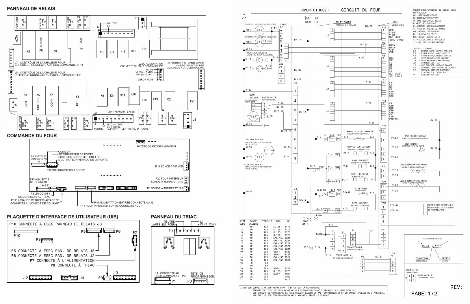
P18 MEAT PROBE
P9 OUTCONNECTSTO J5
P6 PROGRAMMING HEADER
P1 TEMP PROBE
P16 POWER IN CONNECTS TO J2P8 BACKLIGHT POWER CONNECTS
TO POWER SUPPLY
P2 LIN COMM 1CONNECTS TO TRIAC
P13 AUX OUTCONNECTS TO J6
P10 SWITCH 1 OUT
P11 LOWER OVEN OUT CONNECTS TO J7
1
MDLRACK SENSOR DEFEATDOOR SWITCHCOMMON
P20 LOWER OVEN TEMP PROBE
P8 P10 P12 P2
P4 P18
1
1
1
1
1
P7
P16P15P19P13
P1
P17P3
P11P9
BR
OIL
BA
KE
CO
NV
L2 IN
L2 O
UT
DLB
IN
DLB
OU
T
LOW
ER O
VEN
BA
KE
J2 DC POWERCONNECTS TO CONTROL P16
GROUNDVLED (~+7 VDC)VUR (~+15 VDC)
ZERO CROSS
J6 CONTROLS FAN, NIGHT LIGHT, AUX OUTUT
CONNECTS TO CONTROL P13
J5 - HEAT CONTROL LOWER OVEN CONNECTS TOCONTROL P9
J7 - HEAT CONTROL UPPER OVEN CONNECTS TOCONTROL P11
NEUTRALL1
1
1
1
J4
J3
NEUTRALL1 MDL
COOLING FAN - LOW
COOLING FAN - HIGHUPP
ER O
VEN
BR
OIL
BA
KE
CO
NV
DLB
BA
KE BLB
P2
P6P1
PROGRAMMINGHEADER
1
OVEN LAMP CONV FANNEUTRAL L1
P1 CONNECTS TOCONTROL P2
RELAY BOARD
OVEN CONTROL
USER INTERFACE BOARD (UIB) TRIAC BOARD
J2 J4 P9J3
P6P5
P7 CONNECTS TO POWER SUPPLY
P3P10
P9 CONNECTS TO TRIAC
P7
P5 CONNECTS TO ESEC RELAY BOARD J5P6 CONNECTS TO ESEC RELAY BOARD J2
P10 CONNECTS TO ESEC RELAY BOARD J3
p/n 807880709 FR (Rev A 15/04)
AVIS: Cette feuille de données d’entretien est destinée aux personnes ayant reçu une for-mation en électricité et en mécanique, et qui possèdent un niveau de connaissance jugé ac-ceptable dans l’industrie de réparation des appareils électroménagers. Le fabricant ne peut être tenu responsable, ni n’assumer aucune responsabilité, pour toute blessure ou dommage de quelque nature que ce soit pouvant résulter de l’utilisation de cette feuille de données.
NOTE: Cette unité comprend une commande électronique du four. Cette commande de four n’est pas réparable sur place.
PRATIQUES D’ENTRETIEN SÉCURITAIRESPour éviter tout risque de blessure et/ou dommage matériel, il est important que des pratiques d’entretien sécuritaires soient suivies. Voici quelques exemples de pratiques sécuritaires.1. N’essayez jamais de réparer un appareil si vous ne croyez pas avoir les compétences
nécessaires pour le faire de manière satisfaisante et sécuritaire.2. Avant de procéder au service d’entretien ou de déplacer tout appareil ménager,
débranchez le cordon d’alimentation de la prise électrique, réglez le disjoncteur de circuit à OFF, ou enlevez le fusible et fermez le robinet d’alimentation en gaz..
3. N’entravez jamais l’installation adéquate de tout dispositif de sécurité.4. Utilesez que les pièces de remplacement énumérées dans le catalogue pour cet ap-
pareil. La moindre substituion risque de ne pas être conforme aux normes de sécurité établies pour les appareils électroménagers.
5. Mise à la terre: La couleur de codage standard des conducteurs de mise à la terre de sécurité est verte ou verte à barres jaunes. Les conducteurs de mise à la terre ne doivent pas être utilisés comme conducteurs de courant. Il est d’une importance capitale que le technicien d’entretien complète toutes les mises à la terre de sécurité avant de terminer le service. Si cette recommandation n’est pas suivie à la lettre, il en résultera des risques pour les personnes et les biens.
6. Avant de retourner le produit au service de réparation ou d’entretien, assurez-vous que:• Toutes les connexions électriques sont correctes et sécuritaires.• Tous les conducteurs électriques sont correctement préparés et placez de façon
sécuritaire à l’abri des bords tranchants, des composants à température élevée,
FEUILLE DE DONNÉES D’ENTRETIENCuisinières encastrables à alimentation mixte munis d’une commande de four électronique
et des parties mobiles.• Toutes les bornes électriques, connecteurs, réchauffeurs, etc. dénudés sont
espacés convenablement loin de toute pièce en métal et des panneaux.• Toutes les mises à la terre de sécurité (interne et externe) sont correctement et
assemblées de façon sécuritaire.• Tous les panneaux sont correctement et fermement remontés.
CALIBRATION DU FOURRéglez le point de consigne pour une cuisson traditionnelle à 350°F (177°C). Laisser le four préchauffer à la température réglée. Mesurez la température moyenne du four après un min-imum de 5 cycles. Appuyez sur CANCEL pour arrêter ou annuler la cuisson en tout temps.
Ajustement de la température du four1. Appuyez sur USER PREFERENCES jusqu’à ce que vous arriviez à la page UPO (four
du haut). 2. Pour sélectionner le four que vous voulez ajuster, appuyez sur USER PREFERENCES
encore une fois pour changer à UPO dans l’écran du four du bas.3. Entrez la température désirée en appuyant sur les touches + hi ou - lo. La température
peut seulement être ajustée de ± 35°F.4. Appuyez sur START pour accepter les changements et retourner au menu des
préférences.
Note: Modifier la calibration affecte tous les modes de cuisson mais pas les modes de nettoyage et de grillage.
2-VITESSE VENTILATEUR RAFRAÎCHISSANTLes contrôleurs de four électronique dirige vitesse de le ventilateur rafraîchissant. Le venti-lateur rafraîchissant activer à basse vitesse vitesse pendant une cuisson fonction, et il reste allumé jusqu’à ce que du four refroidir. Le haut débit activer pendant grillage (avec la porte ouverte) et pendant clean cycles seul quand la température est plus que approximativement 575ºF/302ºC.
MATRICE D’ANALYSE DU CIRCUIT
Sur le Panneau Relais Sur le Panneau TRIAC Sur le Panneau D’Alimen-
tation
ÉLÉMENTSMoteur
de porteJ3-5
DLBL2 sortie
P1
Vent de refroid basseJ3-7
Vent de refroid hauteJ3-8
Interr de porteP10-3
CuissonP9
GrilP7
Conv.P11
Vent. Conv.P2-7
Lampe du fourP2-1
Cuisson X X X* X X X X*
Maintien chaud X X X
Gril X X X X
Cuisson conv. X X X X X X X**
Rôtissage conv X X X X X X X
Grillage conv. X X X X X
Nettoyage X X X X X
Verrouillage X
Verrouillé
Deverrouillage X
Déverrouillé
Lampe X
Porte ouverte X
Porte fermeé X
Pâte de pain X X X
Le relais sera en opération dans ces conditions seulement
*L’élément de convection ainsi que le ventilateur sont en fonction pour la première élévation de la température
TABLEAU DE TEMPÉRATURE DE LA SONDE vs SA RÉSISTANCE
Temperature Résistance
77 °F / 25°C 50.020 Kohm +/- 6%
122 °F / 50°C 18.020 Kohm +/- 5%
176 °F / 80°C 6.290 Kohm +/- 5%
212 °F / 100°C 3.400 Kohm +/- 5%
Résistance (ohms)1 000 ± 4,0
1 091 ± 5,3
1 453 ± 8,9
1 654 ± 10,8
1 852 ± 13,5
2 047 ± 15,8
2 237 ± 18,5
2 697 ± 24,4
Circuit ouvert/résistance infinie
ÉCHELLE DU DÉTECTEUR DE TEMPÉRATUREÀ RÉSISTANCE
Température °F (°C)32 ± 1,9 (0 ± 1,0)
75 ± 2,5 (24 ± 1,3)
250 ± 4,4 (121 ± 2,4)
350 ± 5,4 (177 ± 3,0)
450 ± 6,9 (232 ± 3,8)
550 ± 8,2 (288 ± 4,5)
650 ± 9,6 (343 ± 5,3)
900 ± 13,6 (482 ±7,5)Circuit de la sonde mise à la
terre à la caisse
MATRICE D’ANALYSE DU CIRCUIT DU FOUR INFÉRIEUR
On Relay Board
ÉLÉMENTS DLB L2 sortie (P2)Cuisson (P10)
Cuisson X X
Maintien chaud X X
IMPORTANTN’ENLEVEZ PAS CE SAC OU NEDÉTRUISEZ PAS SON CONTENU
CONTIENT LES SCHÉMAS DE CÂBLAGE ETLES INFORMATIONS DE RÉPARATION
REMETTRE LE CONTENUDANS LE SAC
DESCRIPTION DES CODES D’ERREUR DE LA COMMANDE DE FOUR
Note: “F1X” indique des erreurs internes de la commande du four; “F3X”, un problème avec la sonde du four et “F9x”, un problème avec le moteur verrou.
Code d erreur/État/Cause Action corrective suggérée
F10 La commande de four a décelé une condition d’emballement possible. La commande présente un relais en court-circuit, (RTD) mauvais fonctionnement de la sonde.
Vérifiez la sonde RTD et remplacez-la si nécessaire. Si le four surchauffe, coupez le courant. S’il continue de surchauffer une fois le courant rétabli, remplacez le panneau de relais et/ou le panneau d’affichage.
F11 Touches en court-circuit: si une touche a été détectée comme enfoncée durant une longue période de temps on la considère comme court-circuitée et une alarme termine toute activité
1) Appuyez sur une touche pour effacer le code d’erreur.2) Si le code réapparaît, remplacez le panneau de commande (clavier). 3) Si le problème persiste, remplacez le panneau d’affichage.
F13 La mémoire interne du contrôle est corrompue.
1) Appuyez sur une touche pour effacer le code d’erreur.2) Débranchez l’appareil, attendez 30 secondes et rebranchez l’appareil. Si le problème réapparaît lors du branchement, changez le panneau d’affichage.
F14 Câble du clavier mal connecté 1) Vérifiez les connexions entre le panneau d’affichage et le clavier (2 câbles ruban). Assurez-vous que les câbles sont bien connectés à chaque extrémité. 2) Si les câbles sont intacts, remplacez le clavier. 3) Si le problème persiste, remplacez le panneau d’affichage.
F15 Problème avec l’auto vérification du contrôleur 1) Un code F15 de la commande du four peut indiquer que la commande ne reçoit pas le signal de synchronisation de la plaque re-lais. Une façon facile de déterminer cela est de débrancher l’appareil, rebrancher-le et démarrer un chronomètre de 1 minute avant que le F15 s’affiche. Si la minuterie fonctionne normalement, la synchronisation a été faite correctement. Si 1:00 demeure affiché et que le compte à rebours ne démarre pas, la synchronisation a échoué. Si la synchronisation a échoué, vérifiez en premier si la plaque relais reçoit 120V correctement (J4 tiges 1 et 3). par la suite, vérifiez le filage entre le connecteur J2 de la plaque relais et le connecteur P16 de la commande du four. Si le courant AC et le filage sont corrects et que le problème est encore présent, remplacez la plaque relais. Si le problème persiste, remplacez la commande de four. 2) Le code F15 peut être causé par un défaut de la commande du four. Si le signal de synchronisation a été vérifié et testé bon, remplacez la commande du four.
F20 Commande du four a détecté un problème de communication avec les contrôleurs d’éléments (ESEC)
1) Est-ce que la plaque de l’interface usager ESEC fonctionne (est-ce que les écrans affichent quelque chose?) Si non, c’est pour cela que la commande ne peut communiquer avec (ESEC n’est pas sous tension). Vérifier la voltage 120VAC à l’entrée de la plaque d’alimentation de l’ESEC située sur le devant de la console (connecteur P1) et le bas voltage provenant de la plaque d’alimentation (connecteur P2) à l’interface usager du ESEC (connecteur P7).2) Vérifier les connexions entre le connecteur P2 de la commande du four et P9 de l’interface usager du ESEC. Ceci est le lien de communication. Vérifier s’il y a du courant. Référer au schéma de câblage.3) Si toutes les étapes précédentes n’ont pas réglées le problème, remplacez l’interface usager du ESEC.4) Si le problème persiste toujours, remplacez la commande du four.
F23 Le contrôleur a manqué sa communication avec le panneau du ventilateur de convection et des lumières.
1) Vérifiez le filage entre P2 sur le panneau d’affichage et P2 sur le panneau du ventilateur de convection et lumières.2) Si les fils sont bons, remplacez le panneau du ventilateur.3) Si le problème persiste, remplacez le panneau d’affichage.
F30 Problème avec le filage de sonde/filage ouvertNote: La commande de four affichera initialement le code “F10”, cela signifie qu’il décèle l’existence d’une condition d’embal-lement.
1) Vérifiez le filage du circuit de la sonde, il est peut-être ouvert ou coupé. 2) Vérifiez la résistance RTD à la température de la pièce (comparez les données au tableau). Si celle-ci ne concorde pas, remplacez
la sonde (RTD).3) Laissez refroidir le four et redémarrez la fonction.4) Si le problème persiste, remplacez le panneau d’affichage.Note: Si F30 ou F31 s’affiche lorsque le four est actif ou lorsqu’il est en train d’entrer dans un mode actif.
F43 La vitesse du ventilateur de refroidissement, lue par l’entrée du tachymètre du conseil EOC-affichage, est anormalement trop lent.
1) Déterminez d’abord si le problème semble être causé par un ventilateur de refroidissement ne tourne pas ou tourne lentement ou par un problème avec la détection de la vitesse du ventilateur. Démarrer une cuisson et vérifier au cours des 15 premières secondes si le ventilateur tourne (doit se sentir l’air se écoulant à travers l’évent dessus de la porte du four supérieur).2) Si le ventilateur ne semble pas être de tourner ou de tourner lentement le 120VAC vérifier au niveau du ventilateur. Si 120VAC est présent au niveau du moteur de ventilateur, mais le ventilateur ne tourne pas remplacer le moteur du ventilateur. Si 120VAC ne est pas présent sur le moteur du ventilateur quand un Cuire est démarré vérifier la connexion à la carte de relais (J3 broche 7) et neutre: il est 120VAC sur la broche J3 7? Est-il atteindre le moteur du ventilateur? Est l’autre borne du moteur du ventilateur connecté à Neutre? Si le harnais ou carte de relais sont défectueux remplacer.3) Si le ventilateur semble être normalement tourner, mais un code d’erreur de F43 est générée, cela signifie qu’il ya un problème avec la lecture du capteur de vitesse du ventilateur. Assurez-vous que la connexion du capteur de vitesse du ventilateur est correctement établie (cf. schéma de câblage), entre le capteur sur le ventilateur et le tableau d’affichage EOC.4) Aux fins de dépannage, il est possible d’entrer dans un mode de test qui indiquera à l’écran la lecture de la vitesse du ventilateur en RPM: pour entrer dans le mode de test, la mise sous tension de l’appareil et à moins de 30 secondes, appuyez et maintenez le four supérieur cuisson et de gril touches pour 3 secondes (jusqu’à ce que vous voyez tous les segments de l’écran allumé). Une fois dans le mode de test, appuyez sur la touche Lumière four supérieur affichera une fois la vitesse du ventilateur dans RPM. En mode normal, le client d’erreur F43 est générée pour une vitesse du ventilateur en dessous d’environ 700 tours par minute.
F44 La vitesse du ventilateur de refroidissement, lue par l’entrée du tachymètre du tableau d’affichage EOC, est anormalement trop rapide.
1) Inspectez le ventilateur de refroidissement. Il ne semble se tourner normalement (flux d’air, bruit)? Vérifiez la pale de ventilateur est bien assemblé.2) Vérifiez que rien ne bloque le flux d’air du ventilateur (qui pourrait faire tourner le ventilateur plus rapide).3) Vérifiez la tension 120VAC sur le ventilateur. Une tension supérieure à 120VAC + 10% pourrait faire aller trop vite.4) Assurez-vous que la connexion du capteur de vitesse du ventilateur est correctement établie (cf. schéma de câblage), entre le capteur sur le ventilateur et le tableau d’affichage EOC.5) Aux fins de dépannage, il est possible d’entrer dans un mode de test qui indiquera à l’écran la lecture de la vitesse du ventilateur en RPM: pour entrer dans le mode de test, la mise sous tension de l’appareil et à moins de 30 secondes, appuyez et maintenez le four supérieur cuisson et de gril touches pour 3 secondes (jusqu’à ce que vous voyez tous les segments de l’écran allumé). Une fois dans le mode de test, appuyez sur la touche Lumière four supérieur affichera une fois la vitesse du ventilateur dans RPM. En mode client normale l’erreur F44 est généré pour une vitesse de ventilateur au-dessus d’environ 2500 RPM.6) Si le problème persiste, remplacer le ventilateur + capteur assemblage et le tableau d’affichage EOC.
F90 Système de verrouillage de porte défectueux 1) Appuyez sur une touche pour effacer le code d’erreur.2) Si cette étape n’élimine pas le problème, coupez le courant pendant 30 secondes et redémarrez l’appareil.3) Vérifiez le filage du moteur verrou, de l’interrupteur verrou et le circuit de l’interrupteur de la porte.4) Débranchez le moteur verrou, appliquez du courant (L1) directement au moteur verrou, si le moteur ne fonctionne pas, remplacez l’assemblage.5) Vérifiez si l’interrupteur verrou A fonctionne adéquatement (Est-ce qu’il permet d’ouvrir et de fermer, vérifiez avec un ohm mètre). Le moteur verrou doit être réactivé tel qu’indiqué à l’étape précédente afin que l’interrupteur s’ouvre et se ferme. Si l’interrupteur verrou est défectueux, remplacez-le.6) Si toutes les étapes mentionnées ci haut échouent, remplacez le panneau de relais ou le panneau électronique analogique dans le cas ou le moteur verrou ne tourne pas.7) Si toutes les étapes mentionnées ci haut échouent, remplacez le panneau électronique analogique dans le cas où le moteur verrou tourne trop faiblement.
P18 SONDE À VIANDE
P9 SORTIE SE CONNECTE AU
J5
P6 TÊTE DE PROGRAMMATION
P1 SONDE À TEMPÉRATURE
P16 ALIMENTATION ENTRÉE CONNECTE AU J2P8 PUISSANCE RÉTROÉCLAIRAGE SE CONNECTE AU SOURCE DE COURANT
P2 LIN COMM 1SE CONNECTE AU TRIAC
P13 AUX SOTIE SE CONNECTE
AU J6
P10 INTERRUPTEUR 1 SORTIE
P11 FOUR INFÉRIEUR SORTIE CONNECTE AU J7
1
MDL - MOTEUR VERROU DE LA PORTEECHEC DU SONDE DES GRILLESINTERRUPTEUR DE PORTECOMMUN
P20 FOUR INFÉRIEUR SONDE À TEMPÉRATURE
P8 P10 P12 P2
P4 P18
1
1
1
1
1
P7
P16P15P19P13
P1
P17P3
P11P9
GR
IL
CU
ISS
ON
CO
NV
L2 E
NT
L2 S
OR
T
DLB
EN
DLB
SO
RT
FOU
R IN
FR
CU
ISS
ON
J2 DC ALIMENTATION CONNECTE AU FOUR COMMANDE P16
TERREVLED (~+7 VDC)VUR (~+15 VDC)
ZERO CROSS
J6 CONTRÔLE DU VENTILATEUR,LUMIÈRE DE NUIT, SORTIE
AUX, RELIÉ À UN CONTRÔLE P13
J5 - CONTRÔLE DE LA CHALEUR FOUR INFÉRIEUR CONNECTE AU FOUR COMMANDER P9
J7 - CONTRÔLE DE LA CHALEUR FOUR SUPÉRIEUR CONNECTE AU FOUR COMMANDER P11
NEUTREL1
1
1
1
J4
J3
NEUTREL1 MDL-MOTEUR
VERROU DELA PORTE
VENT REFROID - BASSE
VENT REFROID - HAUTEFOR
T SU
PER
GR
IL
CU
ISS
ON
CO
NV
DLB
CU
ISS
ON
DLB
P2
P6P1
TÊTE DE PROGRAMMATION
1
LAMPE DU FOUR VENT CONVNEUTRE L1
P1 CONNECTE AUFOUR COMMANDER P2
PANNEAU DE RELAIS
COMMANDE DU FOUR
PLAQUETTE D’INTERFACE DE UTILISATEUR (UIB) PANNEAU DU TRIAC
INTERRUPTEUR PORTE
MOTEUR VERROU
BASSE VITESSE
VENTILATEUR REFROIDISSEMENTHAUTE VITESSE
FOUR DU BAS
ECHEC DU SONDE DES GRILLES
SONDE THERMIQUE DU HAUT
SONDE THERMIQUE DU BAS
TRANSFORMATEUR
SOURCE DE COURRANT
*CERTAINS MODELES
LEGEND/LEGENDE
CONNECTEUR CAVITE
CONNECTEUR
VENTILATEUR REFROIDISSEMENT
DISJONCTEUR THERMIQUE
OVEN LAMP-HALOGENLAMPE DU FOUR-HALOGENE
CIRCUIT DU FOUR
PANNEAU DE RELAIS
LEGEND / LEGENDEC.R. - CENTER REAR/CENTRE ARRIÈRER.F. - RIGHT FRONT/AVANT DROITER.R. - RIGHT REAR/ARRIÈRE DROITE L.F. - LEFT FRONT/AVANT GAUCHEL.R. - LEFT REAR/ARRIÈRE GAUCHELIM. - LIMITER/LIMITEURH.S. - HOT SURFACE/SURFACE CHAUDET.B. - TERMINAL BLOCK/BLOC DE BORNESTHM. - THERMAL CIRCUIT BREAKER/ DISJONCTEUR THERMIQUEFN. - FAN/VENTILATEUR
J2 J4 P9J3
P6P5
P7 CONNECTE À L'ALIMENTATION
P3P10
P9 CONNECTE À TRIAC
P7
P5 CONNECTE À ESEC PAN. DE RELAIS J5P6 CONNECTE À ESEC PAN. DE RELAIS J2
P10 CONNECTE À ESEC PANNEAU DE RELAIS J3
SERVICE DATA SHEETAppliance with Electronic Surface Element Control (ESEC 20)
NOTICE: This service data sheet is intended for use by persons having electrical and mechanical training and a level of knowledge of these subjects generally considered acceptable in the appliance repair trade. The manufacturer cannot be responsible, nor assume any liability, for injury or damage of any kind arising from the use of this data sheet.
IMPORTANT NOTE: This unit includes an ESEC (electronic surface element control). This board is not field-repairable.
Safe Servicing PracticesTo avoid the possibility of personal injury and/or property damage, it is important that safe servicing practices be observed. The following are some, but not all, examples of safe practices.
1. Do not attempt a product repair if you have any doubts as to your ability to complete it in a safe and satisfactory manner.
2. Before servicing or moving an appliance, remove power cord from electric outlet, trip circuit breaker to Off, or remove fuse.
3. Never interfere with the proper installation of any safety device.4. Use only replacement parts specified for this appliance. Substitutions may
not comply with safety standards set for home appliances.5. Grounding: The standard color coding for safety ground wires is green
or green with yellow stripes. Ground leads are not to be used as current carrying conductors. It is extremely important that the service technician reestablish all safety grounds prior to completion of service. Failure to do so will create a potential hazard.
6. Prior to returning the product to service, ensure that:• All electric connections are correct and secure.• All electrical leads are properly dressed and secured away from sharp
edges, high-temperature components, and moving parts.• All uninsulated electrical terminals, connectors, heaters, etc. are ade-
quately spaced away from all metal parts and panels.• All safety grounds (both internal and external) are correctly and secure-
ly reassembled.• All panels are properly and securely reassembled.
Resistance (ohms)1000 ± 4.0
1091 ± 5.3
1453 ± 8.9
1654 ± 10.8
1852 ± 13.5
2047 ± 15.8
2237 ± 18.5
2697 ± 24.4Open circuit/infinite resistance
RTD SCALE
Temperature °F (°C)32 ± 1.9 (0 ± 1.0)
75 ± 2.5 (24 ± 1.3)
250 ± 4.4 (121 ± 2.4)
350 ± 5.4 (177 ± 3.0)
450 ± 6.9 (232 ± 3.8)
550 ± 8.2 (288 ± 4.5)
650 ± 9.6 (343 ± 5.3)
900 ± 13.6 (482 ±7.5)Probe circuit to case ground
IMPORTANTDO NOT REMOVE THIS BAG
OR DESTROY THE CONTENTSWIRING DIAGRAMS AND SERVICE
INFORMATION ENCLOSEDREPLACE CONTENTS IN BAG
p/n 807880712 EN (Rev A 15/04)
ELECTRONIC SURFACE ELEMENT CONTROL (ESEC) FAULT CODE DESCRIPTIONS
Code Condition/Cause Suggested Corrective Action
E11 Shorted keypad 1. Disconnect power, wait 30 seconds and reapply power.2. If fault returns upon power-up, replace user interface board (UIB).3. If fault returns, replace glass touch panel.
E13 Bad EEPROM 1. Disconnect power, wait 30 seconds and reapply power.2. If fault returns upon power-up, replace user interface board (UIB).
E14 Touch panel display tail missing 1. Check connection between UIB (connector J2, J3 & J4) and glass touch panel.2. If connections are good, replace UIB.3. If problem persists, replace touch panel.
E15 ESEC self-test failed, or thermal cutoff open
An E15 error code on the ESEC may indicate the User Interface Board is not receiving a synchronization signal from the ESEC relay board. 1. Check first if the ESEC relay board is receiving 120VAC correctly (J1 pin 1 and 3).2. Check the wiring between connector J2 on the ESEC relay board and connector P6 on the UIB.3. If AC power and wiring looks good and the problem is still there, replace the UIB.4. If problem persists, replace the ESEC relay board.
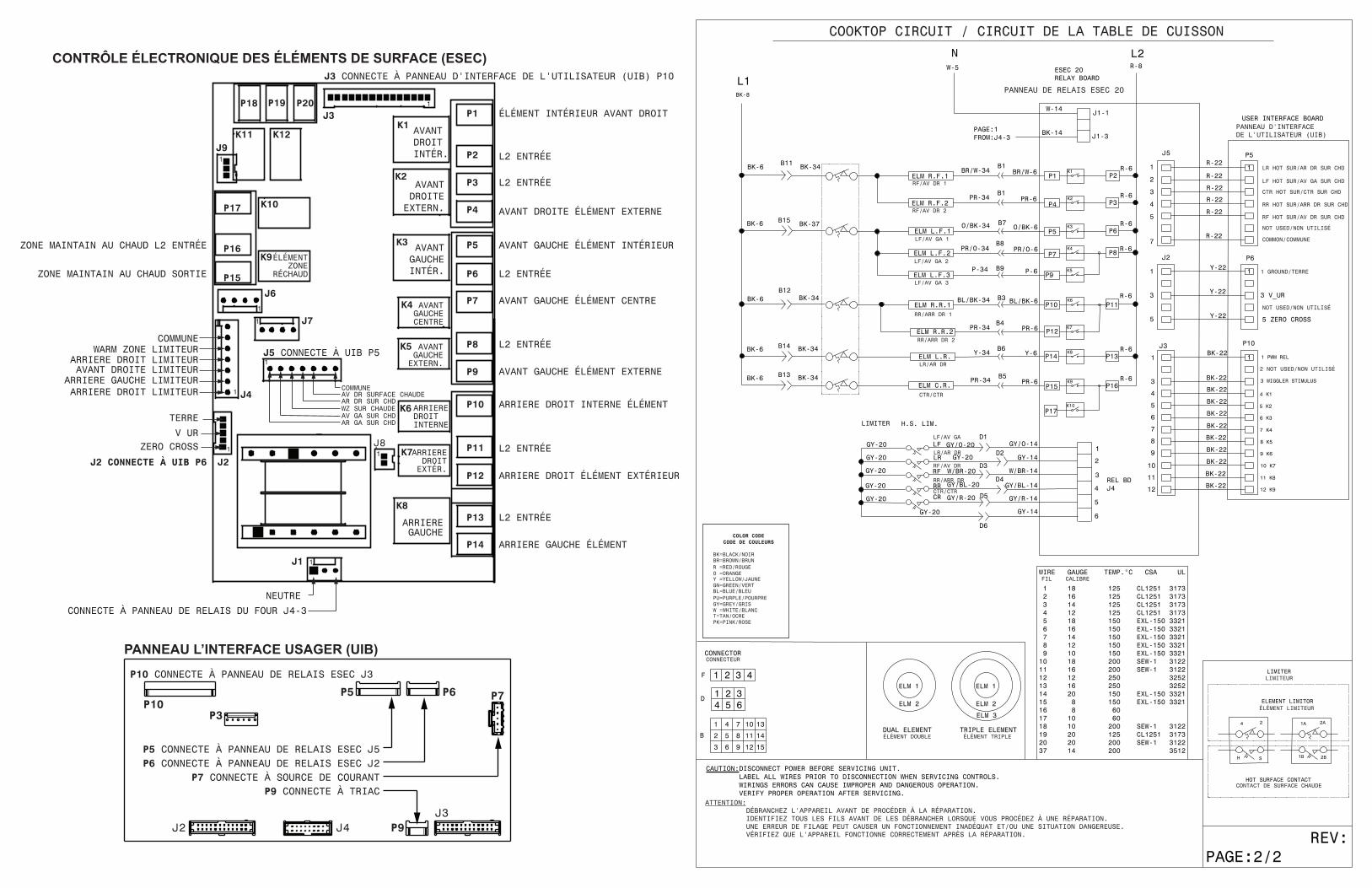
USER INTERFACE BOARD (UIB)
J2 J4 P9J3
P6P5
P7 CONNECTS TO POWER SUPPLY
P3P10
P9 CONNECTS TO TRIAC
P7
P5 CONNECTS TO ESEC RELAY BOARD J5P6 CONNECTS TO ESEC RELAY BOARD J2
P10 CONNECTS TO ESEC RELAY BOARD J3
P18 P19 P20 1
K1
K2
K3
K4
K5
K6
K7
K8
J1
1
1
J8
P1
P2
P3
P4
P5
P6
P7
P8
P9
P10
P11
P12
P13
P14
J91
K11 K12
K10
K9
P17
P16
P15
J61
1 J7
J41
1
J2 CONNECTS TO UIB P6
LEFT REAR ELEMENT
L2 IN
RIGHT FRONT OUTER ELEMENT
RIGHT FRONT INNER ELEMENT
LEFT FRONT INNER ELEMENT
LEFT FRONT MIDDLE ELEMENT
LEFT FRONT OUTER ELEMENT
RIGHT REAR OUTER ELEMENT
RIGHT REAR INNER ELEMENT
WARMZONE
ELEMENT
CONNECTS TO OVENRELAY BOARD J4-3
NEUTRAL
LEFT FRONT LIMITERLEFT REAR LIMITER
RIGHT FRONT LIMITERRIGHT REAR LIMITERWARM ZONE LIMITER
GROUND
V URZERO CROSS
WARM ZONE L2 IN
WARM ZONE OUT
1J5 CONNECTS TO UIB P5
RF HOT SURRR HOT SURWZ HOT SURLF HOT SURLR HOT SUR
COMMON
J2
J3
J3 CONNECTS TO UIB P10
RIGHTFRONTINNER
RIGHTFRONTOUTER
LEFTFRONTINNER
LEFTFRONT
MIDDLE
LEFTFRONTOUTER
RIGHTREAR
INNER
RIGHTREAR
OUTER
LEFTREAR
COMMON
L2 IN
L2 IN
L2 IN
L2 IN
L2 IN
ELECTRONIC SURFACE ELEMENT CONTROL (ESEC) BOARD
FICHE TECHNIQUECONTRÔLE ÉLECTRONIQUE DES ÉLÉMENTS DE SURFACE (ESEC)
p/n 807880712 FR (Rev A 15/04)
CODES - CONTRÔLE ÉLECTRONIQUE DES ÉLÉMENTS DE SURFACE (ESEC)
Code Condition/Cause Suggested Corrective Action
E11 Touche en court-circuit. 1. Débranchez l’appareil, attendez 30 secondes et rebranchez-le.2. Si le code est toujours, remplacez le panneau l’interface usager (UIB).3. Si le code est toujours, remplacez le clavier tactile.
E13 EEPROM corrompu 1. Débranchez l’appareil, attendez 30 secondes et rebranchez-le.2. Si le code est toujours, remplacez le panneau l’interface usager (UIB).
E14 Câble du clavier mal connecté 1. Vérifiez la connexion entre le panneau d’affichage (connecteur J2, J3 & J4) et le clavier vitrifié tactile2. Si les connexions sont bonnes, changez le panneau l’interface usager (UIB).3. Si le problème persiste, changez le clavier tactile.
E15 Problème avec l’auto-vérification du contrôleur
Un code E15 sur le ESEC peut indiquer que l’interface usager ne reçoit pas lesignal de synchronisation de la plaque relais ESEC.1. Vérifiez premièrement si la plaque relais reçoit le courant 120VAC correctement (J1 tiges 1 et 3).2. Vérifiez le filage entre le connecteur J2 sur la plaque relais ESEC et le connecteur P6 sur l’interface usager (UIB).3. Si le courant AC et le filage sont corrects et que le problème est encore présent, remplacez l’interface usager
(UIB).4. Si le problème persiste, remplacez la plaque relais ESEC
Résistance (ohms)1 000 ± 4,0
1 091 ± 5,3
1 453 ± 8,9
1 654 ± 10,8
1 852 ± 13,5
2 047 ± 15,8
2 237 ± 18,5
2 697 ± 24,4
Circuit ouvert/résistance infinie
ÉCHELLE DU DÉTECTEUR DE TEMPÉRATUREÀ RÉSISTANCE
Température °F (°C)32 ± 1,9 (0 ± 1,0)
75 ± 2,5 (24 ± 1,3)
250 ± 4,4 (121 ± 2,4)
350 ± 5,4 (177 ± 3,0)
450 ± 6,9 (232 ± 3,8)
550 ± 8,2 (288 ± 4,5)
650 ± 9,6 (343 ± 5,3)
900 ± 13,6 (482 ±7,5)Circuit de la sonde mise à la
terre à la caisse
IMPORTANTN’ENLEVEZ PAS CE SAC OU NEDÉTRUISEZ PAS SON CONTENU
CONTIENT LES SCHÉMAS DE CÂBLAGE ETLES INFORMATIONS DE RÉPARATION
REMETTRE LE CONTENUDANS LE SAC
AVIS - Cette feuille de données d’entretien est destinée aux personnes ayant reçu une formation en électricité et en mécanique, et qui possèdent un niveau de connaissance jugé acceptable dans l’industrie de réparation des appareils électroménagers. Le fabricant ne peut être tenu responsable, ni n’assumer aucune responsabilité, pour toute blessure ou dommage de quelque nature que ce soit pouvant résulter de l’utilisation de cette feuille de données.
PRATIQUES D’ENTRETIEN SÉCURITAIREPour éviter tout risque de blessure et/ou dommage matériel, il est important que des pratiques d’entretien sécuritaires soient suivies. Voici quelques exemples de pratiques sécuritaires.1. N’essayez jamais de réparer un appareil si vous ne croyez pas avoir les
compétences nécessaires pour le faire de manière satisfaisante et sécuritaire.2. Avant de procéder au service d’entretien ou de déplacer tout appareil ménager,
débranchez le cordon d’alimentation de la prise électrique, réglez le disjoncteur de circuit à OFF, ou enlevez le fusible et fermez le robinet d’alimentation en gaz.
3. N’entravez jamais l’installation adéquate de tout dispositif de sécurité.4. UTILISEZ QUE les pièces de remplacement énumérées dans le catalogue pour
cet appareil. LA MOINDRE SUBSTITUTION risque de ne pas être conforme aux normes de sécurité établies pour les appareils électroménagers.
5. MISE À LA TERRE: La couleur de codage standard des conducteurs de mise à la terre de sécurité est VERTE ou VERTE À BARRES JAUNES. Les conducteurs de mise à la terre ne doivent pas être utilisés comme conducteurs de courant. Il est d’une IMPORTANCE CAPITALE que le technicien d’entretien complète toutes les mises à la terre de sécurité avant de terminer le service. Si cette recommandation n’est pas suivie à la lettre, il en résultera des risques pour les personnes et les biens.
6. Avant de retourner le produit au service de réparation ou d’entretien, assurez-vous que:• Toutes les connexions électriques sont correctes et sécuritaires• Tous les conducteurs électriques sont correctement préparés et placez de
façon sécuritaire à l’abri des bords tranchants, des composants à température élevée, et des parties mobiles.
• Toutes les bornes électriques, connecteurs, réchauffeurs, etc. dénudés sont espacés convenablement loin de toute pièce en métal et des panneaux.
• Toutes les mises à la terre de sécurité (interne et externe) sont correctement et assemblées de façon sécuritaire.
• Tous les panneaux sont correctement et fermement remontés.
COOKTOP CIRCUIT / CIRCUIT DE LA TABLE DE CUISSON
PANNEAU DE RELAIS ESEC 20
PANNEAU D'INTERFACE DE L'UTILISATEUR (UIB)
LIMITEUR
ÉLÉMENT LIMITEUR
CONTACT DE SURFACE CHAUDE
1 GROUND/TERRE
COMMON/COMMUNE
NOT USED/NON UTILISÉ
RF HOT SUR/AV DR SUR CHD
RR HOT SUR/ARR DR SUR CHD
CTR HOT SUR/CTR SUR CHD
LF HOT SUR/AV GA SUR CHD
LR HOT SUR/AR DR SUR CHD
NOT USED/NON UTILISÉ
2 NOT USED/NON UTILISÉ
FIL CALIBRE
ÉLÉMENT TRIPLEÉLÉMENT DOUBLE
ATTENTION: DÉBRANCHEZ L'APPAREIL AVANT DE PROCÉDER À LA RÉPARATION. IDENTIFIEZ TOUS LES FILS AVANT DE LES DÉBRANCHER LORSQUE VOUS PROCÉDEZ À UNE RÉPARATION. UNE ERREUR DE FILAGE PEUT CAUSER UN FONCTIONNEMENT INADÉQUAT ET/OU UNE SITUATION DANGEREUSE. VÉRIFIEZ QUE L'APPAREIL FONCTIONNE CORRECTEMENT APRÈS LA RÉPARATION.