75
SHIBAURA DIESEL ENGINE MODELS: S773L, N843, N843L WORKSHOP MANUAL SUPPORTED BY HUSTLER TURF EQUIPMENT AND EXCEL INDUSTRIES, INC.
SHIBAURA DIESEL ENGINE
MODELS: S773L, N843, N843L
WORKSHOP MANUAL
SUPPORTED BY HUSTLER TURF EQUIPMENT AND EXCEL INDUSTRIES, INC.
FOREWORDThis workshop Manual includes repair and adjustment procedures required for the diesel engine models S773L, N843,and N843L.When servicing to keep the engine in the best condition, you will find this Manual very useful as a guidebook.This Workshop Manual was prepared in Jul. 2008. Specifications contained in this Manual are subject to change withoutnotice for subsequent engineering changes.
109823_2/09 c-2
Table of Contents
FOREWORD . . . . . . . . . . . . . . . . . . . . . . . . . . . . . . . . . . . . . . . . . . . . . . . . . . . . . .c-2
Section 1: Safety . . . . . . . . . . . . . . . . . . . . . . . . . . . . . . . . . . . . . . . . . . . 1-1Before beginning service or repair . . . . . . . . . . . . . . . . . . . . . . . . . . . . . . . . . . . . . .1-1Avoid Fire Hazards . . . . . . . . . . . . . . . . . . . . . . . . . . . . . . . . . . . . . . . . . . . . . . . . .1-1Prepare For Emergencies . . . . . . . . . . . . . . . . . . . . . . . . . . . . . . . . . . . . . . . . . . . .1-1Engine Starting Safety . . . . . . . . . . . . . . . . . . . . . . . . . . . . . . . . . . . . . . . . . . . . . . .1-1Prevent Battery Explosions . . . . . . . . . . . . . . . . . . . . . . . . . . . . . . . . . . . . . . . . . . .1-1Avoid Acid Burns . . . . . . . . . . . . . . . . . . . . . . . . . . . . . . . . . . . . . . . . . . . . . . . . . . .1-2Avoid High-pressure Fluids . . . . . . . . . . . . . . . . . . . . . . . . . . . . . . . . . . . . . . . . . . .1-2Understand Correct Service . . . . . . . . . . . . . . . . . . . . . . . . . . . . . . . . . . . . . . . . . .1-2General Maintenance Precautions . . . . . . . . . . . . . . . . . . . . . . . . . . . . . . . . . . . . .1-2Fuel Handling. . . . . . . . . . . . . . . . . . . . . . . . . . . . . . . . . . . . . . . . . . . . . . . . . . . . . .1-3Wear Protective Clothing . . . . . . . . . . . . . . . . . . . . . . . . . . . . . . . . . . . . . . . . . . . . .1-3
Section 2: General . . . . . . . . . . . . . . . . . . . . . . . . . . . . . . . . . . . . . . . . . 2-1General Notes Before Service . . . . . . . . . . . . . . . . . . . . . . . . . . . . . . . . . . . . . . . . .2-1Fundamental Instructions On Service . . . . . . . . . . . . . . . . . . . . . . . . . . . . . . . . . . .2-1Torque Specifications . . . . . . . . . . . . . . . . . . . . . . . . . . . . . . . . . . . . . . . . . . . . . . .2-2Engine Sectional Drawing . . . . . . . . . . . . . . . . . . . . . . . . . . . . . . . . . . . . . . . . . . . .2-3Specifications. . . . . . . . . . . . . . . . . . . . . . . . . . . . . . . . . . . . . . . . . . . . . . . . . . . . . .2-4Engine Removal . . . . . . . . . . . . . . . . . . . . . . . . . . . . . . . . . . . . . . . . . . . . . . . . . . .2-5Parts and Descriptions. . . . . . . . . . . . . . . . . . . . . . . . . . . . . . . . . . . . . . . . . . . . . . .2-6
Section 3: Disassembly And Inspection Of Engine . . . . . . . . . . . . . . . . . 3-1Rocker arm assembly . . . . . . . . . . . . . . . . . . . . . . . . . . . . . . . . . . . . . . . . . . . . . . .3-1Cylinder head assembly . . . . . . . . . . . . . . . . . . . . . . . . . . . . . . . . . . . . . . . . . . . . .3-2Cylinder block . . . . . . . . . . . . . . . . . . . . . . . . . . . . . . . . . . . . . . . . . . . . . . . . . . . . .3-4Piston and piston ring . . . . . . . . . . . . . . . . . . . . . . . . . . . . . . . . . . . . . . . . . . . . . . .3-5Connecting rod . . . . . . . . . . . . . . . . . . . . . . . . . . . . . . . . . . . . . . . . . . . . . . . . . . . .3-7Connecting rod bearing . . . . . . . . . . . . . . . . . . . . . . . . . . . . . . . . . . . . . . . . . . . . . .3-7Disassembly, inspection and reassembly of bearing holder . . . . . . . . . . . . . . . . . .3-9Crankshaft bearing (bushing) . . . . . . . . . . . . . . . . . . . . . . . . . . . . . . . . . . . . . . . . .3-9Crankshaft . . . . . . . . . . . . . . . . . . . . . . . . . . . . . . . . . . . . . . . . . . . . . . . . . . . . . . . .3-10Flywheel and ring gear . . . . . . . . . . . . . . . . . . . . . . . . . . . . . . . . . . . . . . . . . . . . . .3-11Cam shaft assembly . . . . . . . . . . . . . . . . . . . . . . . . . . . . . . . . . . . . . . . . . . . . . . . .3-12Timing gear . . . . . . . . . . . . . . . . . . . . . . . . . . . . . . . . . . . . . . . . . . . . . . . . . . . . . . .3-12Oil flow . . . . . . . . . . . . . . . . . . . . . . . . . . . . . . . . . . . . . . . . . . . . . . . . . . . . . . . . . . .3-13Oil pump . . . . . . . . . . . . . . . . . . . . . . . . . . . . . . . . . . . . . . . . . . . . . . . . . . . . . . . . .3-14Oil filter. . . . . . . . . . . . . . . . . . . . . . . . . . . . . . . . . . . . . . . . . . . . . . . . . . . . . . . . . . .3-14Water pump assembly and thermostat . . . . . . . . . . . . . . . . . . . . . . . . . . . . . . . . . .3-15Radiator . . . . . . . . . . . . . . . . . . . . . . . . . . . . . . . . . . . . . . . . . . . . . . . . . . . . . . . . . .3-15Fuel filter . . . . . . . . . . . . . . . . . . . . . . . . . . . . . . . . . . . . . . . . . . . . . . . . . . . . . . . . .3-16Governor . . . . . . . . . . . . . . . . . . . . . . . . . . . . . . . . . . . . . . . . . . . . . . . . . . . . . . . . .3-16Injection pump . . . . . . . . . . . . . . . . . . . . . . . . . . . . . . . . . . . . . . . . . . . . . . . . . . . . .3-16Nozzle and holder . . . . . . . . . . . . . . . . . . . . . . . . . . . . . . . . . . . . . . . . . . . . . . . . . .3-17
Section 4: Engine Re-assembly . . . . . . . . . . . . . . . . . . . . . . . . . . . . . . . 4-1Relief valve assembly with O-Ring. . . . . . . . . . . . . . . . . . . . . . . . . . . . . . . . . . . . . .4-1Crank shaft and bearing holder assembly . . . . . . . . . . . . . . . . . . . . . . . . . . . . . . . .4-1Measure the end play of crankshaft. . . . . . . . . . . . . . . . . . . . . . . . . . . . . . . . . . . . .4-1Oil seal . . . . . . . . . . . . . . . . . . . . . . . . . . . . . . . . . . . . . . . . . . . . . . . . . . . . . . . . . . .4-2Rear plate . . . . . . . . . . . . . . . . . . . . . . . . . . . . . . . . . . . . . . . . . . . . . . . . . . . . . . . .4-2
t-1 109823 2/09
Flywheel . . . . . . . . . . . . . . . . . . . . . . . . . . . . . . . . . . . . . . . . . . . . . . . . . . . . . . . . . 4-2Piston and connecting rod assembly . . . . . . . . . . . . . . . . . . . . . . . . . . . . . . . . . . . 4-3Suction pipe · Suction filter . . . . . . . . . . . . . . . . . . . . . . . . . . . . . . . . . . . . . . . . . . . 4-3Oil pan. . . . . . . . . . . . . . . . . . . . . . . . . . . . . . . . . . . . . . . . . . . . . . . . . . . . . . . . . . . 4-4Oil dipstick · Dipstick guide . . . . . . . . . . . . . . . . . . . . . . . . . . . . . . . . . . . . . . . . . . . 4-4Front plate . . . . . . . . . . . . . . . . . . . . . . . . . . . . . . . . . . . . . . . . . . . . . . . . . . . . . . . . 4-4Camshaft assembly · Tachometer shaft plate. . . . . . . . . . . . . . . . . . . . . . . . . . . . . 4-4Idle gear · Oil pump assembly. . . . . . . . . . . . . . . . . . . . . . . . . . . . . . . . . . . . . . . . . 4-5Timing gear case · Cover . . . . . . . . . . . . . . . . . . . . . . . . . . . . . . . . . . . . . . . . . . . . 4-5Crankshaft pulley . . . . . . . . . . . . . . . . . . . . . . . . . . . . . . . . . . . . . . . . . . . . . . . . . . 4-6Injection pump assembly. . . . . . . . . . . . . . . . . . . . . . . . . . . . . . . . . . . . . . . . . . . . . 4-6‘Oil filter . . . . . . . . . . . . . . . . . . . . . . . . . . . . . . . . . . . . . . . . . . . . . . . . . . . . . . . . . . 4-6Engine stop solenoid. . . . . . . . . . . . . . . . . . . . . . . . . . . . . . . . . . . . . . . . . . . . . . . . 4-6Cylinder head assembly . . . . . . . . . . . . . . . . . . . . . . . . . . . . . . . . . . . . . . . . . . . . . 4-7Cap · Push rod · Rocker arm assembly . . . . . . . . . . . . . . . . . . . . . . . . . . . . . . . . . 4-8Valve clearance adjustment . . . . . . . . . . . . . . . . . . . . . . . . . . . . . . . . . . . . . . . . . . 4-8Oil pressure switch . . . . . . . . . . . . . . . . . . . . . . . . . . . . . . . . . . . . . . . . . . . . . . . . . 4-9Oil pipe . . . . . . . . . . . . . . . . . . . . . . . . . . . . . . . . . . . . . . . . . . . . . . . . . . . . . . . . . . 4-9Water pump assembly · Bypass hose. . . . . . . . . . . . . . . . . . . . . . . . . . . . . . . . . . . 4-9Valve cover . . . . . . . . . . . . . . . . . . . . . . . . . . . . . . . . . . . . . . . . . . . . . . . . . . . . . . . 4-9Glow plug, Connector . . . . . . . . . . . . . . . . . . . . . . . . . . . . . . . . . . . . . . . . . . . . . . . 4-9
Section 5: Electrical Systems. . . . . . . . . . . . . . . . . . . . . . . . . . . . . . . . . 5-1Fuel Shutoff Solenoid . . . . . . . . . . . . . . . . . . . . . . . . . . . . . . . . . . . . . . . . . . . . . . . 5-1Engine Glow Plugs . . . . . . . . . . . . . . . . . . . . . . . . . . . . . . . . . . . . . . . . . . . . . . . . . 5-2Engine Oil Pressure Switch. . . . . . . . . . . . . . . . . . . . . . . . . . . . . . . . . . . . . . . . . . . 5-3Alternator (40 amp version) (No. 185046320). . . . . . . . . . . . . . . . . . . . . . . . . . . . . 5-4 Alternator diagnostic procedures . . . . . . . . . . . . . . . . . . . . . . . . . . . . . . . . . . . . . . 5-5Maintenance . . . . . . . . . . . . . . . . . . . . . . . . . . . . . . . . . . . . . . . . . . . . . . . . . . . . . . 5-11Trouble Shooting. . . . . . . . . . . . . . . . . . . . . . . . . . . . . . . . . . . . . . . . . . . . . . . . . . . 5-12Starter Motor (M001T66081) (No. 185086551). . . . . . . . . . . . . . . . . . . . . . . . . . . . 5-13Maintenance . . . . . . . . . . . . . . . . . . . . . . . . . . . . . . . . . . . . . . . . . . . . . . . . . . . . . . 5-18Trouble shooting . . . . . . . . . . . . . . . . . . . . . . . . . . . . . . . . . . . . . . . . . . . . . . . . . . . 5-19
Section 6: Trouble-Shooting . . . . . . . . . . . . . . . . . . . . . . . . . . . . . . . . . 6-1
Section 7: Servicing Specifications . . . . . . . . . . . . . . . . . . . . . . . . . . . . 7-1
Index . . . . . . . . . . . . . . . . . . . . . . . . . . . . . . . . . . . . . . . . . . . . . . . . . . . i-1
109823 2/09 t-2
SECTION 1: SAFETY
This safety alert symbol is used to call attention to amessage intended to provide a reasonable degree ofPERSONAL SAFETY for operators and other personsduring the normal operation and servicing of thisequipment.
BEFORE BEGINNING SERVICE OR REPAIR1. Read and understand all instructions and safety
warnings in this manual and on any decals on theequipment.
2. Make sure engine and work area are clean.3. Place engine or machine on stable, level work
area and/or use an approved engine stand.4. Stop engine and remove ignition key.5. Allow engine to cool before preforming service.6. Disconnect negative (-) battery cable before pre-
forming service or repair.
DANGER—denotes immediate hazards which WILLresult in severe personal injury or death.
WARNING—denotes a hazard or unsafe practice whichCOULD result in severe personal injury or death.
NOTE:—emphasizes general information worthy ofspecial attention.
All operators and mechanics should read this manual, andbe instructed about safe operating and maintenanceprocedures. If the operators or mechanics cannot readand understand English, it is the owner’s responsibility toexplain this material to them.To reduce the potential for injury, comply with these safetyinstructions and always pay attention to the safety alert ▲symbol, which means DANGER or WARNING—“personalsafety instructions.” Failure to comply with the instructionsmay result in personal injury or death.
AVOID FIRE HAZARDS▲ Be prepared if an accident or fire should occur.
Know where the first aid kit and the fireextinguishers are located and how to use them.
▲ Provide adequate ventilation when chargingbatteries.
▲ Do not smoke near battery.▲ Never check fuel level with an open flame.▲ Never use an open flame to look for leaks
anywhere on the equipment.▲ Never use an open flame as light anywhere on or
around the equipment.▲ When preparing engine for storage, remember
that inhibitor is volatile and therefore dangerous.Seal and tape openings after adding the inhibitor.Keep container tightly closed when not in use.
▲ Inspect electrical wiring for worn or frayedinsulation. Install new wiring if wires are damaged.
PREPARE FOR EMERGENCIES▲ Be prepared if a fire starts.▲ Keep a first aid kit and fire extinguishers available.▲ Keep emergency numbers for doctor, ambulance
service, hospital, and fire department near thetelephone.
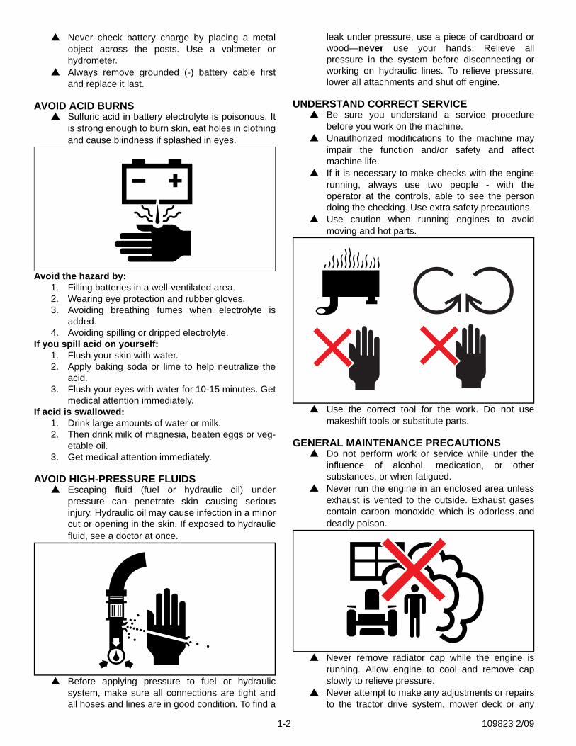
ENGINE STARTING SAFETY▲ Do not start engine by shorting across starter
terminals.
▲ Unauthorized modifications to the engine mayimpair the function and/or safety and affect enginelife.
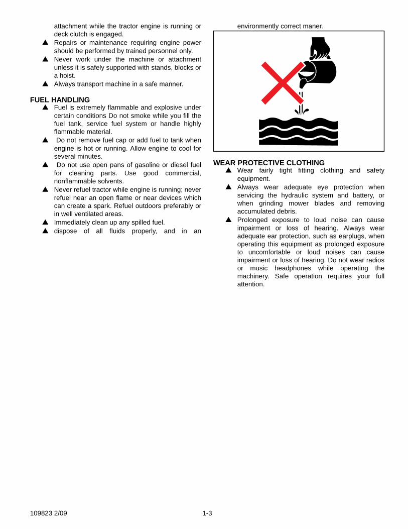
PREVENT BATTERY EXPLOSIONS
▲ Battery gas can explode. Keep sparks and flamesaway from batteries. Use a flashlight to checkbattery electrolyte level.
109823 2/09 1-1
▲ Never check battery charge by placing a metalobject across the posts. Use a voltmeter orhydrometer.
▲ Always remove grounded (-) battery cable firstand replace it last.
AVOID ACID BURNS▲ Sulfuric acid in battery electrolyte is poisonous. It
is strong enough to burn skin, eat holes in clothingand cause blindness if splashed in eyes.
Avoid the hazard by:1. Filling batteries in a well-ventilated area.2. Wearing eye protection and rubber gloves.3. Avoiding breathing fumes when electrolyte is
added.4. Avoiding spilling or dripped electrolyte.
If you spill acid on yourself:1. Flush your skin with water.2. Apply baking soda or lime to help neutralize the
acid.3. Flush your eyes with water for 10-15 minutes. Get
medical attention immediately.If acid is swallowed:
1. Drink large amounts of water or milk.2. Then drink milk of magnesia, beaten eggs or veg-
etable oil.3. Get medical attention immediately.
AVOID HIGH-PRESSURE FLUIDS▲ Escaping fluid (fuel or hydraulic oil) under
pressure can penetrate skin causing seriousinjury. Hydraulic oil may cause infection in a minorcut or opening in the skin. If exposed to hydraulicfluid, see a doctor at once.
▲ Before applying pressure to fuel or hydraulicsystem, make sure all connections are tight andall hoses and lines are in good condition. To find a
leak under pressure, use a piece of cardboard orwood—never use your hands. Relieve allpressure in the system before disconnecting orworking on hydraulic lines. To relieve pressure,lower all attachments and shut off engine.
UNDERSTAND CORRECT SERVICE▲ Be sure you understand a service procedure
before you work on the machine.▲ Unauthorized modifications to the machine may
impair the function and/or safety and affectmachine life.
▲ If it is necessary to make checks with the enginerunning, always use two people - with theoperator at the controls, able to see the persondoing the checking. Use extra safety precautions.
▲ Use caution when running engines to avoidmoving and hot parts.
▲ Use the correct tool for the work. Do not usemakeshift tools or substitute parts.
GENERAL MAINTENANCE PRECAUTIONS▲ Do not perform work or service while under the
influence of alcohol, medication, or othersubstances, or when fatigued.
▲ Never run the engine in an enclosed area unlessexhaust is vented to the outside. Exhaust gasescontain carbon monoxide which is odorless anddeadly poison.
▲ Never remove radiator cap while the engine isrunning. Allow engine to cool and remove capslowly to relieve pressure.
▲ Never attempt to make any adjustments or repairsto the tractor drive system, mower deck or any
1-2 109823 2/09
attachment while the tractor engine is running ordeck clutch is engaged.
▲ Repairs or maintenance requiring engine powershould be performed by trained personnel only.
▲ Never work under the machine or attachmentunless it is safely supported with stands, blocks ora hoist.
▲ Always transport machine in a safe manner.
FUEL HANDLING▲ Fuel is extremely flammable and explosive under
certain conditions Do not smoke while you fill thefuel tank, service fuel system or handle highlyflammable material.
▲ Do not remove fuel cap or add fuel to tank whenengine is hot or running. Allow engine to cool forseveral minutes.
▲ Do not use open pans of gasoline or diesel fuelfor cleaning parts. Use good commercial,nonflammable solvents.
▲ Never refuel tractor while engine is running; neverrefuel near an open flame or near devices whichcan create a spark. Refuel outdoors preferably orin well ventilated areas.
▲ Immediately clean up any spilled fuel.▲ dispose of all fluids properly, and in an
environmently correct maner.
WEAR PROTECTIVE CLOTHING▲ Wear fairly tight fitting clothing and safety
equipment.▲ Always wear adequate eye protection when
servicing the hydraulic system and battery, orwhen grinding mower blades and removingaccumulated debris.
▲ Prolonged exposure to loud noise can causeimpairment or loss of hearing. Always wearadequate ear protection, such as earplugs, whenoperating this equipment as prolonged exposureto uncomfortable or loud noises can causeimpairment or loss of hearing. Do not wear radiosor music headphones while operating themachinery. Safe operation requires your fullattention.
109823 2/09 1-3

1-4 109823 2/09
SECTION 2: GENERAL
General Notes Before Service1. Clean the exterior of the engine, drain oil, fuel and cooling water as necessary before disas-
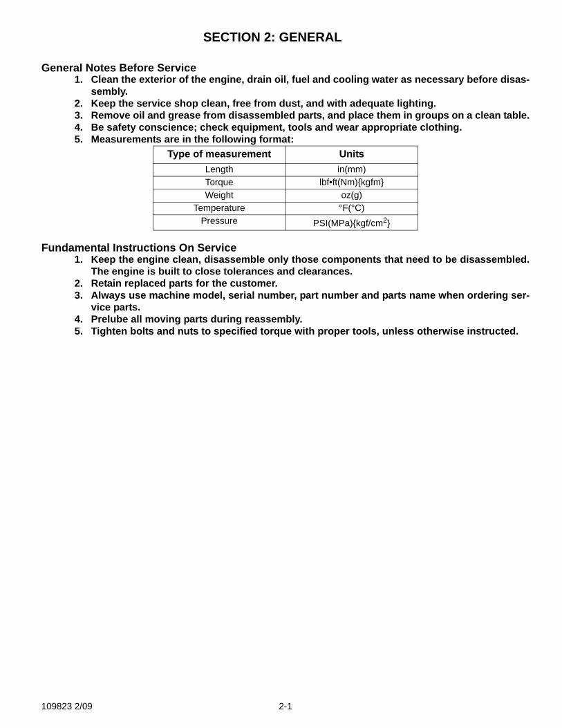
sembly.2. Keep the service shop clean, free from dust, and with adequate lighting.3. Remove oil and grease from disassembled parts, and place them in groups on a clean table.4. Be safety conscience; check equipment, tools and wear appropriate clothing.5. Measurements are in the following format:
Fundamental Instructions On Service1. Keep the engine clean, disassemble only those components that need to be disassembled.
The engine is built to close tolerances and clearances.2. Retain replaced parts for the customer.3. Always use machine model, serial number, part number and parts name when ordering ser-
vice parts.4. Prelube all moving parts during reassembly.5. Tighten bolts and nuts to specified torque with proper tools, unless otherwise instructed.
Type of measurement UnitsLength in(mm)Torque lbf•ft(Nm){kgfm}Weight oz(g)
Temperature °F(°C)Pressure PSI(MPa){kgf/cm2}
109823 2/09 2-1
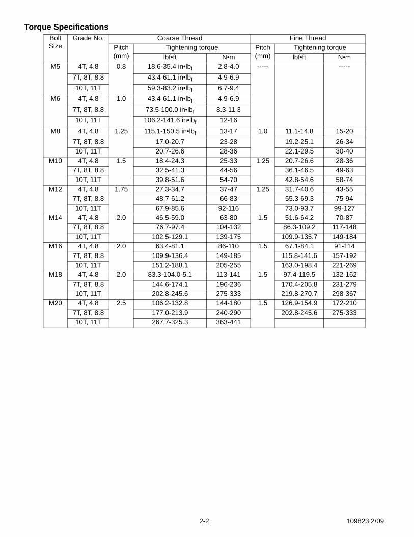
Torque SpecificationsBolt Size
Grade No. Coarse Thread Fine ThreadPitch (mm)
Tightening torque Pitch (mm)
Tightening torquelbf•ft N•m lbf•ft N•m
M5 4T, 4.8 0.8 18.6-35.4 in•lbf 2.8-4.0 ----- -----7T, 8T, 8.8 43.4-61.1 in•lbf 4.9-6.910T, 11T 59.3-83.2 in•lbf 6.7-9.4
M6 4T, 4.8 1.0 43.4-61.1 in•lbf 4.9-6.97T, 8T, 8.8 73.5-100.0 in•lbf 8.3-11.310T, 11T 106.2-141.6 in•lbf 12-16
M8 4T, 4.8 1.25 115.1-150.5 in•lbf 13-17 1.0 11.1-14.8 15-207T, 8T, 8.8 17.0-20.7 23-28 19.2-25.1 26-3410T, 11T 20.7-26.6 28-36 22.1-29.5 30-40
M10 4T, 4.8 1.5 18.4-24.3 25-33 1.25 20.7-26.6 28-367T, 8T, 8.8 32.5-41.3 44-56 36.1-46.5 49-6310T, 11T 39.8-51.6 54-70 42.8-54.6 58-74
M12 4T, 4.8 1.75 27.3-34.7 37-47 1.25 31.7-40.6 43-557T, 8T, 8.8 48.7-61.2 66-83 55.3-69.3 75-9410T, 11T 67.9-85.6 92-116 73.0-93.7 99-127
M14 4T, 4.8 2.0 46.5-59.0 63-80 1.5 51.6-64.2 70-877T, 8T, 8.8 76.7-97.4 104-132 86.3-109.2 117-14810T, 11T 102.5-129.1 139-175 109.9-135.7 149-184
M16 4T, 4.8 2.0 63.4-81.1 86-110 1.5 67.1-84.1 91-1147T, 8T, 8.8 109.9-136.4 149-185 115.8-141.6 157-19210T, 11T 151.2-188.1 205-255 163.0-198.4 221-269
M18 4T, 4.8 2.0 83.3-104.0-5.1 113-141 1.5 97.4-119.5 132-1627T, 8T, 8.8 144.6-174.1 196-236 170.4-205.8 231-27910T, 11T 202.8-245.6 275-333 219.8-270.7 298-367
M20 4T, 4.8 2.5 106.2-132.8 144-180 1.5 126.9-154.9 172-2107T, 8T, 8.8 177.0-213.9 240-290 202.8-245.6 275-33310T, 11T 267.7-325.3 363-441
2-2 109823 2/09
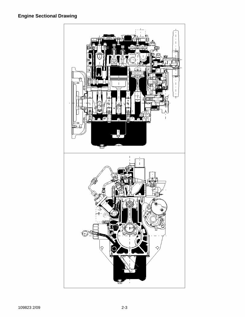
Engine Sectional Drawing
109823 2/09 2-3
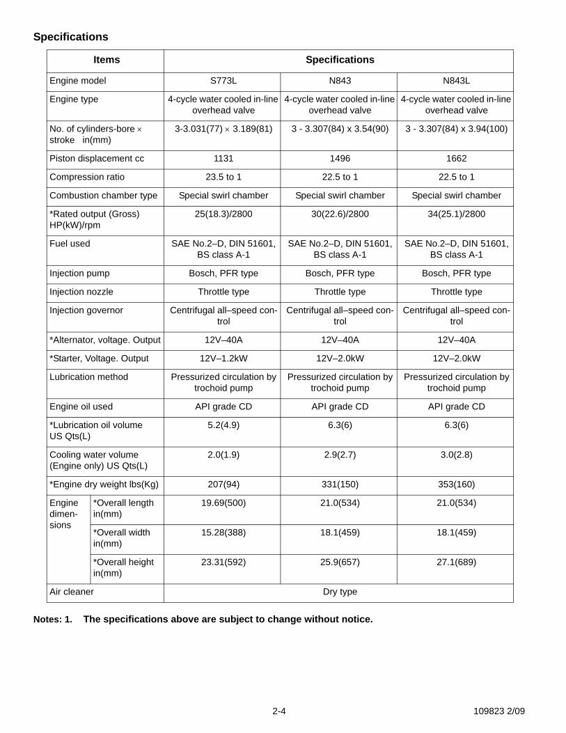
Specifications
Notes: 1. The specifications above are subject to change without notice.
Items Specifications
Engine model S773L N843 N843L
Engine type 4-cycle water cooled in-line overhead valve
4-cycle water cooled in-line overhead valve
4-cycle water cooled in-line overhead valve
No. of cylinders-bore × stroke in(mm)
3-3.031(77) × 3.189(81) 3 - 3.307(84) x 3.54(90) 3 - 3.307(84) x 3.94(100)
Piston displacement cc 1131 1496 1662
Compression ratio 23.5 to 1 22.5 to 1 22.5 to 1
Combustion chamber type Special swirl chamber Special swirl chamber Special swirl chamber
*Rated output (Gross) HP(kW)/rpm
25(18.3)/2800 30(22.6)/2800 34(25.1)/2800
Fuel used SAE No.2–D, DIN 51601, BS class A-1
SAE No.2–D, DIN 51601, BS class A-1
SAE No.2–D, DIN 51601, BS class A-1
Injection pump Bosch, PFR type Bosch, PFR type Bosch, PFR type
Injection nozzle Throttle type Throttle type Throttle type
Injection governor Centrifugal all–speed con-trol
Centrifugal all–speed con-trol
Centrifugal all–speed con-trol
*Alternator, voltage. Output 12V–40A 12V–40A 12V–40A
*Starter, Voltage. Output 12V–1.2kW 12V–2.0kW 12V–2.0kW
Lubrication method Pressurized circulation by trochoid pump
Pressurized circulation by trochoid pump
Pressurized circulation by trochoid pump
Engine oil used API grade CD API grade CD API grade CD
*Lubrication oil volume US Qts(L)
5.2(4.9) 6.3(6) 6.3(6)
Cooling water volume (Engine only) US Qts(L)
2.0(1.9) 2.9(2.7) 3.0(2.8)
*Engine dry weight lbs(Kg) 207(94) 331(150) 353(160)
Engine dimen-sions
*Overall length in(mm)
19.69(500) 21.0(534) 21.0(534)
*Overall width in(mm)
15.28(388) 18.1(459) 18.1(459)
*Overall height in(mm)
23.31(592) 25.9(657) 27.1(689)
Air cleaner Dry type
2-4 109823 2/09
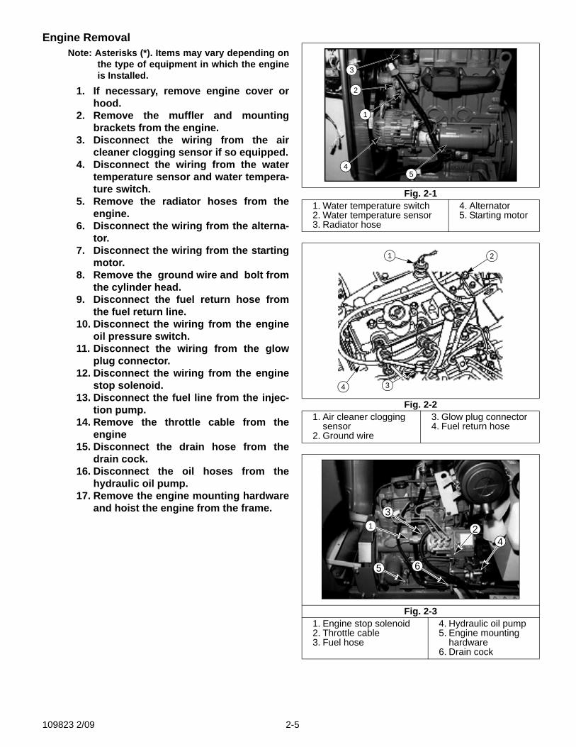
Engine RemovalNote: Asterisks (*). Items may vary depending on
the type of equipment in which the engineis Installed.
1. If necessary, remove engine cover orhood.
2. Remove the muffler and mountingbrackets from the engine.
3. Disconnect the wiring from the aircleaner clogging sensor if so equipped.
4. Disconnect the wiring from the watertemperature sensor and water tempera-ture switch.
5. Remove the radiator hoses from theengine.
6. Disconnect the wiring from the alterna-tor.
7. Disconnect the wiring from the startingmotor.
8. Remove the ground wire and bolt fromthe cylinder head.
9. Disconnect the fuel return hose fromthe fuel return line.
10. Disconnect the wiring from the engineoil pressure switch.
11. Disconnect the wiring from the glowplug connector.
12. Disconnect the wiring from the enginestop solenoid.
13. Disconnect the fuel line from the injec-tion pump.
14. Remove the throttle cable from theengine
15. Disconnect the drain hose from thedrain cock.
16. Disconnect the oil hoses from thehydraulic oil pump.
17. Remove the engine mounting hardwareand hoist the engine from the frame.
Fig. 2-11. Water temperature switch2. Water temperature sensor3. Radiator hose
4. Alternator5. Starting motor
Fig. 2-21. Air cleaner clogging
sensor2. Ground wire
3. Glow plug connector4. Fuel return hose
Fig. 2-31. Engine stop solenoid2. Throttle cable3. Fuel hose
4. Hydraulic oil pump5. Engine mounting
hardware6. Drain cock
3
2
1
45
4 3
1 2
31 2
4
65
109823 2/09 2-5
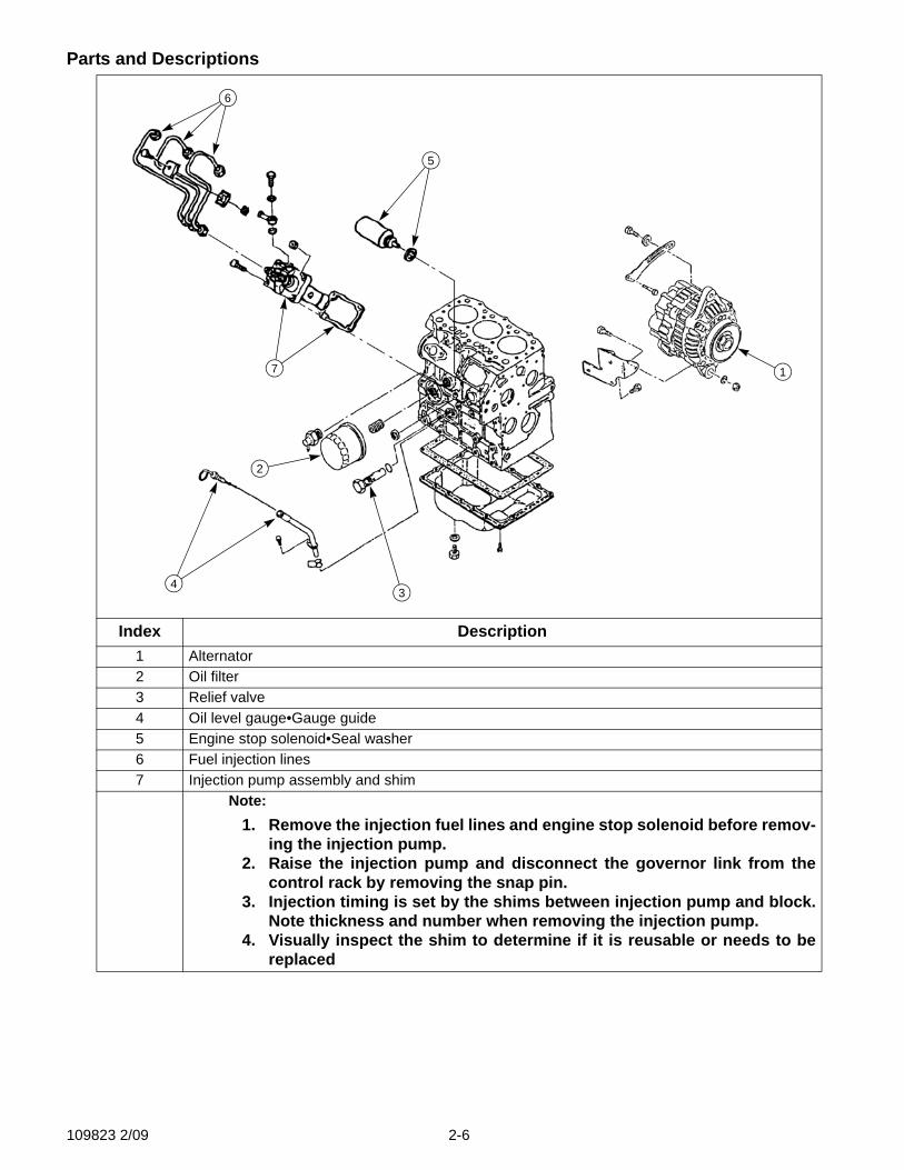
Parts and Descriptions
Index Description1 Alternator2 Oil filter3 Relief valve4 Oil level gauge•Gauge guide5 Engine stop solenoid•Seal washer6 Fuel injection lines7 Injection pump assembly and shim
Note: 1. Remove the injection fuel lines and engine stop solenoid before remov-
ing the injection pump.2. Raise the injection pump and disconnect the governor link from the
control rack by removing the snap pin.3. Injection timing is set by the shims between injection pump and block.
Note thickness and number when removing the injection pump.4. Visually inspect the shim to determine if it is reusable or needs to be
replaced
5
1
2
43
6
7
109823 2/09 2-6
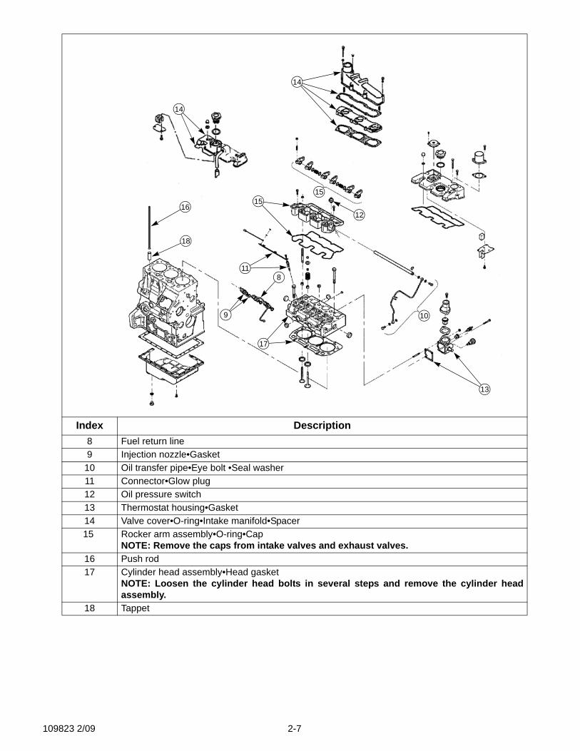
Index Description8 Fuel return line9 Injection nozzle•Gasket
10 Oil transfer pipe•Eye bolt •Seal washer11 Connector•Glow plug12 Oil pressure switch13 Thermostat housing•Gasket14 Valve cover•O-ring•Intake manifold•Spacer15 Rocker arm assembly•O-ring•Cap
NOTE: Remove the caps from intake valves and exhaust valves.16 Push rod17 Cylinder head assembly•Head gasket
NOTE: Loosen the cylinder head bolts in several steps and remove the cylinder headassembly.
18 Tappet
9
8
13
10
11
17
16
18
15
12
14
14
15
109823 2/09 2-7
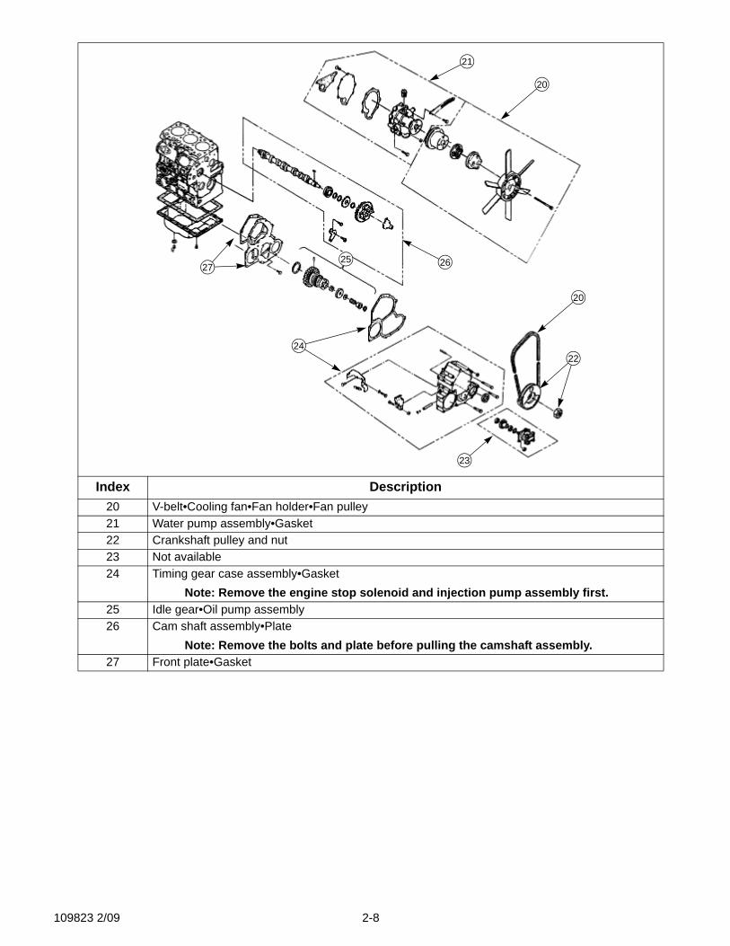
Index Description20 V-belt•Cooling fan•Fan holder•Fan pulley21 Water pump assembly•Gasket22 Crankshaft pulley and nut23 Not available24 Timing gear case assembly•Gasket
Note: Remove the engine stop solenoid and injection pump assembly first.25 Idle gear•Oil pump assembly26 Cam shaft assembly•Plate
Note: Remove the bolts and plate before pulling the camshaft assembly.27 Front plate•Gasket
20
21
20
22
23
24
25 2627
109823 2/09 2-8
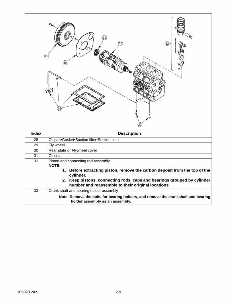
Index Description28 Oil pan•Gasket•Suction filter•Suction pipe29 Fly wheel30 Rear plate or Flywheel cover31 Oil seal32 Piston and connecting rod assembly
NOTE: 1. Before extracting piston, remove the carbon deposit from the top of the
cylinder.2. Keep pistons, connecting rods, caps and bearings grouped by cylinder
number and reassemble to their original locations.33 Crank shaft and bearing holder assembly
Note: Remove the bolts for bearing holders, and remove the crankshaft and bearingholder assembly as an assembly.
28
29
30
31
33 32
33
109823 2/09 2-9

2-10 109823 2/09
SECTION 3: DISASSEMBLY AND INSPECTION OF ENGINE
Caution: before starting disassembly
1. Check the cylinder block and cylinder head for wear, leakage or damage.2. Clean oil passages with compressed air and check for clogging.3. Thoroughly clean parts to remove dust, contaminated oil, carbon, and other foreign mate-
rial.4. Remove carbon deposits on the piston, cylinder head, valves, etc. being careful not to dam-
age parts. (Especially for aluminum alloy parts.)5. Valves, pistons, connecting rods, bearings and other parts, should be marked indicating
cylinder number and reassembled to the original cylinder location.
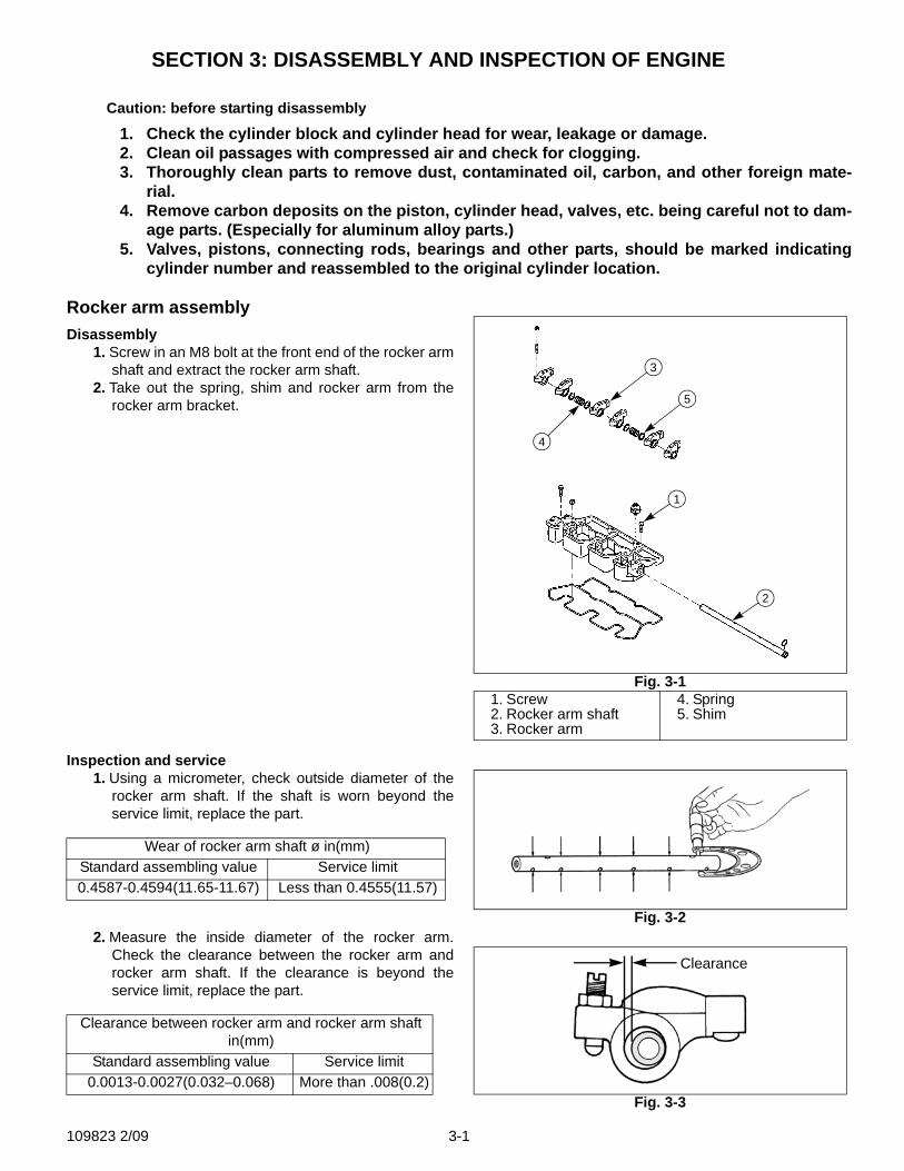
Rocker arm assemblyDisassembly
1. Screw in an M8 bolt at the front end of the rocker armshaft and extract the rocker arm shaft.
2. Take out the spring, shim and rocker arm from therocker arm bracket.
Inspection and service1. Using a micrometer, check outside diameter of the
rocker arm shaft. If the shaft is worn beyond theservice limit, replace the part.
2. Measure the inside diameter of the rocker arm.Check the clearance between the rocker arm androcker arm shaft. If the clearance is beyond theservice limit, replace the part.
Wear of rocker arm shaft ø in(mm)Standard assembling value Service limit0.4587-0.4594(11.65-11.67) Less than 0.4555(11.57)
Clearance between rocker arm and rocker arm shaft in(mm)
Standard assembling value Service limit0.0013-0.0027(0.032–0.068) More than .008(0.2)
Fig. 3-11. Screw2. Rocker arm shaft3. Rocker arm
4. Spring5. Shim
3
5
1
2
4
Fig. 3-2
Fig. 3-3
Clearance
109823 2/09 3-1
3. Check the valve cap-contact surface for unevenwear and streaks. If wear is insignificant, grind flatwith oilstone or grinder, otherwise, replace.
Cylinder head assemblyDisassembly
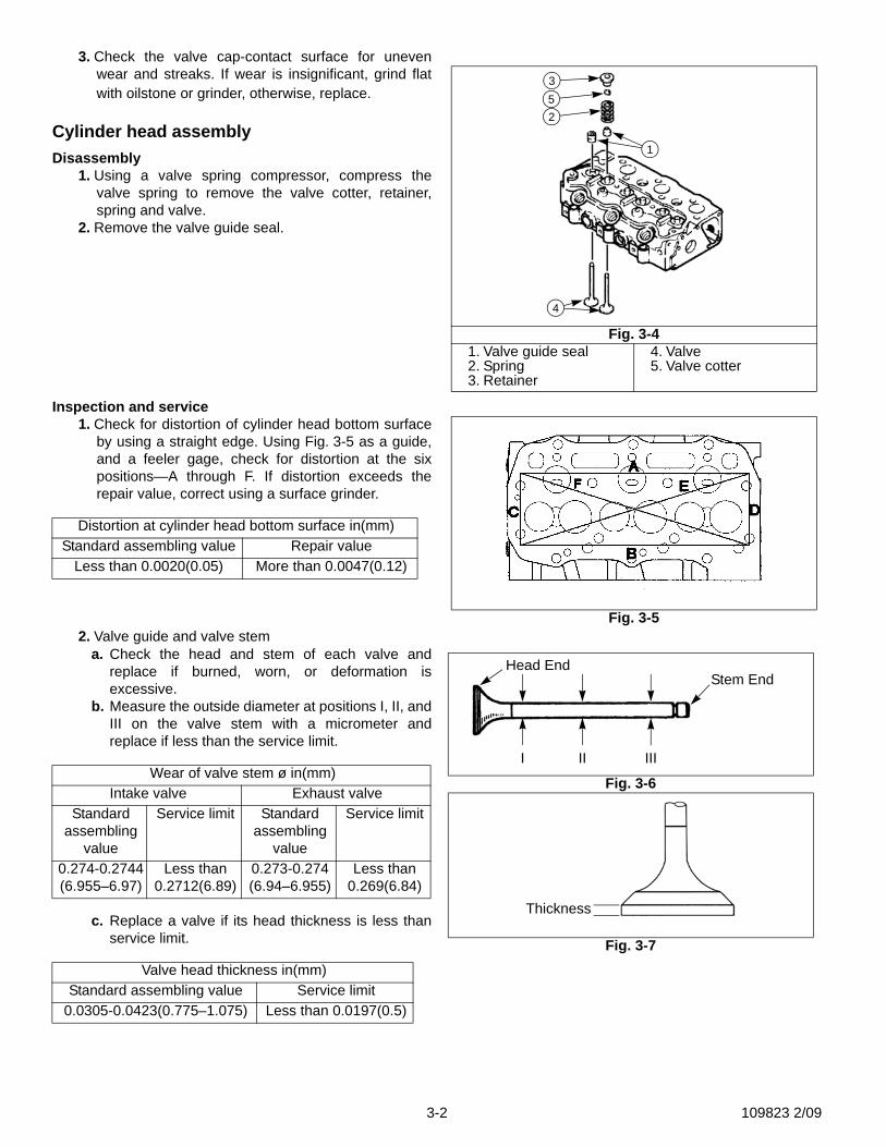
1. Using a valve spring compressor, compress thevalve spring to remove the valve cotter, retainer,spring and valve.
2. Remove the valve guide seal.
Inspection and service1. Check for distortion of cylinder head bottom surface
by using a straight edge. Using Fig. 3-5 as a guide,and a feeler gage, check for distortion at the sixpositions—A through F. If distortion exceeds therepair value, correct using a surface grinder.
2. Valve guide and valve stema. Check the head and stem of each valve and
replace if burned, worn, or deformation isexcessive.
b. Measure the outside diameter at positions I, II, andIII on the valve stem with a micrometer andreplace if less than the service limit.
c. Replace a valve if its head thickness is less thanservice limit.
Distortion at cylinder head bottom surface in(mm)Standard assembling value Repair value
Less than 0.0020(0.05) More than 0.0047(0.12)
Wear of valve stem ø in(mm)Intake valve Exhaust valve
Standard assembling
value
Service limit Standard assembling
value
Service limit
0.274-0.2744(6.955–6.97)
Less than 0.2712(6.89)
0.273-0.274(6.94–6.955)
Less than 0.269(6.84)
Valve head thickness in(mm)Standard assembling value Service limit
0.0305-0.0423(0.775–1.075) Less than 0.0197(0.5)
Fig. 3-41. Valve guide seal2. Spring3. Retainer
4. Valve5. Valve cotter
1
253
4
Fig. 3-5
Fig. 3-6
Fig. 3-7
I II III
Stem EndHead End
Thickness
3-2 109823 2/09
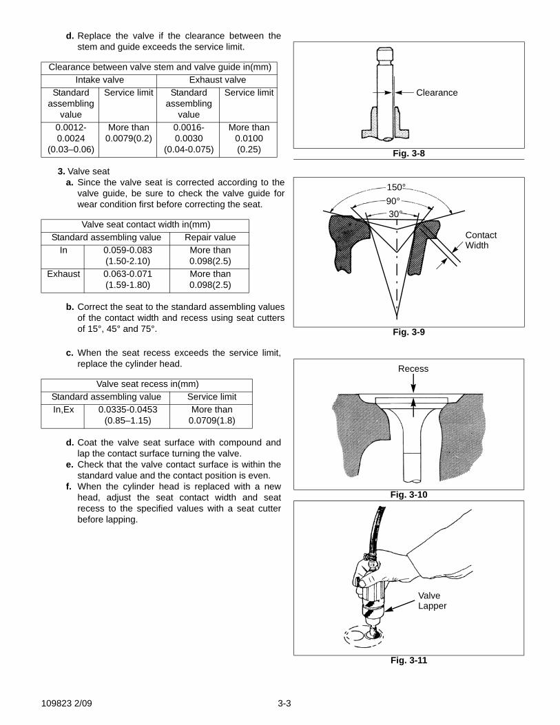
d. Replace the valve if the clearance between thestem and guide exceeds the service limit.
3. Valve seata. Since the valve seat is corrected according to the
valve guide, be sure to check the valve guide forwear condition first before correcting the seat.
b. Correct the seat to the standard assembling valuesof the contact width and recess using seat cuttersof 15°, 45° and 75°.
c. When the seat recess exceeds the service limit,replace the cylinder head.
d. Coat the valve seat surface with compound andlap the contact surface turning the valve.
e. Check that the valve contact surface is within thestandard value and the contact position is even.
f. When the cylinder head is replaced with a newhead, adjust the seat contact width and seatrecess to the specified values with a seat cutterbefore lapping.
Clearance between valve stem and valve guide in(mm)Intake valve Exhaust valve
Standard assembling
value
Service limit Standard assembling
value
Service limit
0.0012-0.0024
(0.03–0.06)
More than 0.0079(0.2)
0.0016-0.0030
(0.04-0.075)
More than 0.0100(0.25)
Valve seat contact width in(mm)Standard assembling value Repair value
In 0.059-0.083(1.50-2.10)
More than 0.098(2.5)
Exhaust 0.063-0.071(1.59-1.80)
More than 0.098(2.5)
Valve seat recess in(mm)Standard assembling value Service limitIn,Ex 0.0335-0.0453
(0.85–1.15)More than
0.0709(1.8)
Fig. 3-8
Clearance
Fig. 3-9
150°90°30°
ContactWidth
Fig. 3-10
Fig. 3-11
Recess
ValveLapper
109823 2/09 3-3
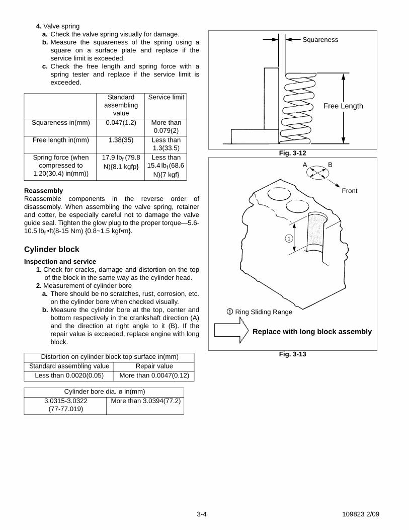
4. Valve springa. Check the valve spring visually for damage.b. Measure the squareness of the spring using a
square on a surface plate and replace if theservice limit is exceeded.
c. Check the free length and spring force with aspring tester and replace if the service limit isexceeded.
ReassemblyReassemble components in the reverse order ofdisassembly. When assembling the valve spring, retainerand cotter, be especially careful not to damage the valveguide seal. Tighten the glow plug to the proper torque—5.6-10.5 lbf •ft(8-15 Nm) {0.8~1.5 kgf•m}.
Cylinder blockInspection and service
1. Check for cracks, damage and distortion on the topof the block in the same way as the cylinder head.
2. Measurement of cylinder borea. There should be no scratches, rust, corrosion, etc.
on the cylinder bore when checked visually.b. Measure the cylinder bore at the top, center and
bottom respectively in the crankshaft direction (A)and the direction at right angle to it (B). If therepair value is exceeded, replace engine with longblock.
Standard assembling
value
Service limit
Squareness in(mm) 0.047(1.2) More than 0.079(2)
Free length in(mm) 1.38(35) Less than 1.3(33.5)
Spring force (when compressed to
1.20(30.4) in(mm))
17.9 lbf (79.8 N){8.1 kgfp}
Less than 15.4 lbf (68.6
N){7 kgf}
Distortion on cylinder block top surface in(mm)Standard assembling value Repair value
Less than 0.0020(0.05) More than 0.0047(0.12)
Cylinder bore dia. ø in(mm)3.0315-3.0322
(77-77.019)More than 3.0394(77.2)
Fig. 3-12
Fig. 3-13
Squareness
Free Length
Replace with long block assembly
A B
Front
1
Ring Sliding Range
3-4 109823 2/09
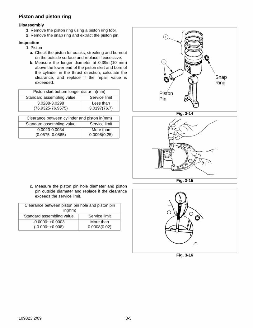
Piston and piston ringDisassembly
1. Remove the piston ring using a piston ring tool.2. Remove the snap ring and extract the piston pin.
Inspection1. Piston
a. Check the piston for cracks, streaking and burnouton the outside surface and replace if excessive.
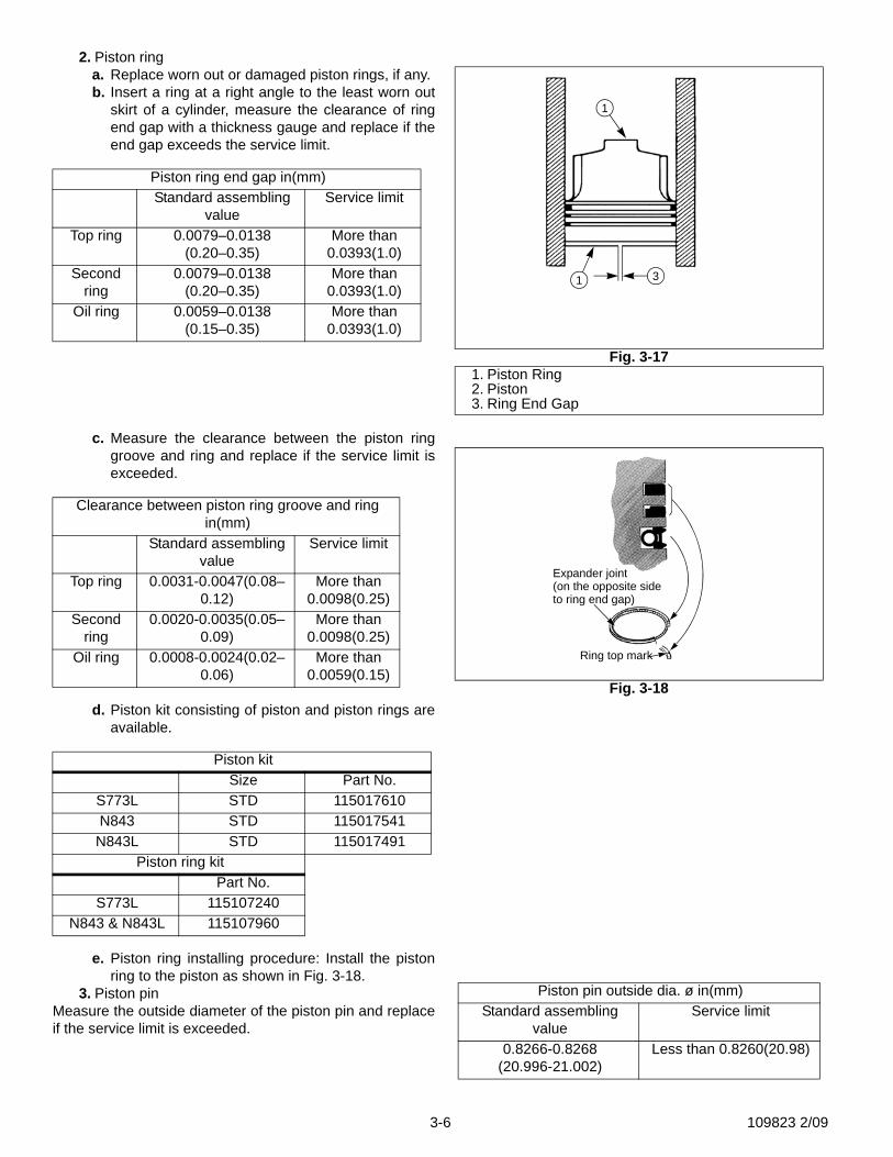
b. Measure the longer diameter at 0.39in.(10 mm)above the lower end of the piston skirt and bore ofthe cylinder in the thrust direction, calculate theclearance, and replace if the repair value isexceeded.
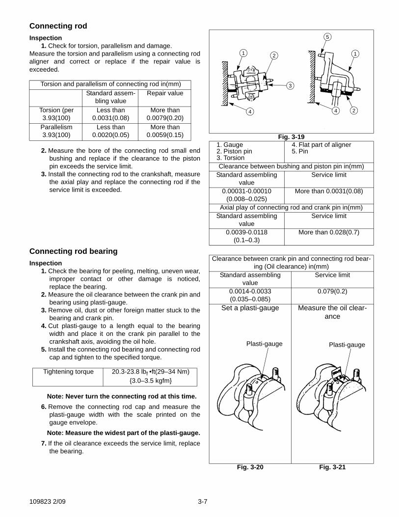
c. Measure the piston pin hole diameter and pistonpin outside diameter and replace if the clearanceexceeds the service limit.
Piston skirt bottom longer dia .ø in(mm)Standard assembling value Service limit
3.0288-3.0298(76.9325-76.9575)
Less than 3.0197(76.7)
Clearance between cylinder and piston in(mm)Standard assembling value Service limit
0.0023-0.0034(0.0575–0.0865)
More than 0.0098(0.25)
Clearance between piston pin hole and piston pin in(mm)
Standard assembling value Service limit-0.0000~+0.0003(-0.000~+0.008)
More than 0.0008(0.02)
Fig. 3-14
Fig. 3-15
SnapRing
PistonPin
1
1
Fig. 3-16
109823 2/09 3-5
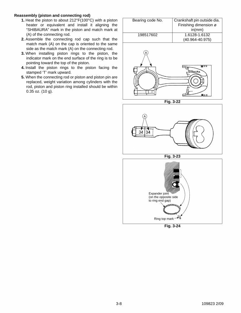
2. Piston ringa. Replace worn out or damaged piston rings, if any.b. Insert a ring at a right angle to the least worn out
skirt of a cylinder, measure the clearance of ringend gap with a thickness gauge and replace if theend gap exceeds the service limit.
c. Measure the clearance between the piston ringgroove and ring and replace if the service limit isexceeded.
d. Piston kit consisting of piston and piston rings areavailable.
e. Piston ring installing procedure: Install the pistonring to the piston as shown in Fig. 3-18.
3. Piston pinMeasure the outside diameter of the piston pin and replaceif the service limit is exceeded.
Piston ring end gap in(mm)Standard assembling
valueService limit
Top ring 0.0079–0.0138(0.20–0.35)
More than 0.0393(1.0)
Second ring
0.0079–0.0138(0.20–0.35)
More than 0.0393(1.0)
Oil ring 0.0059–0.0138(0.15–0.35)
More than 0.0393(1.0)
Clearance between piston ring groove and ring in(mm)
Standard assembling value
Service limit
Top ring 0.0031-0.0047(0.08–0.12)
More than 0.0098(0.25)
Second ring
0.0020-0.0035(0.05–0.09)
More than 0.0098(0.25)
Oil ring 0.0008-0.0024(0.02–0.06)
More than 0.0059(0.15)
Piston kitSize Part No.
S773L STD 115017610N843 STD 115017541N843L STD 115017491
Piston ring kitPart No.
S773L 115107240N843 & N843L 115107960
Fig. 3-171. Piston Ring2. Piston3. Ring End Gap
31
1
Fig. 3-18
Expander joint(on the opposite sideto ring end gap)
Ring top mark
Piston pin outside dia. ø in(mm)Standard assembling
valueService limit
0.8266-0.8268(20.996-21.002)
Less than 0.8260(20.98)
3-6 109823 2/09
Connecting rodInspection
1. Check for torsion, parallelism and damage.Measure the torsion and parallelism using a connecting rodaligner and correct or replace if the repair value isexceeded.
2. Measure the bore of the connecting rod small endbushing and replace if the clearance to the pistonpin exceeds the service limit.
3. Install the connecting rod to the crankshaft, measurethe axial play and replace the connecting rod if theservice limit is exceeded.
Connecting rod bearingInspection
1. Check the bearing for peeling, melting, uneven wear,improper contact or other damage is noticed,replace the bearing.
2. Measure the oil clearance between the crank pin andbearing using plasti-gauge.
3. Remove oil, dust or other foreign matter stuck to thebearing and crank pin.
4. Cut plasti-gauge to a length equal to the bearingwidth and place it on the crank pin parallel to thecrankshaft axis, avoiding the oil hole.
5. Install the connecting rod bearing and connecting rodcap and tighten to the specified torque.
Note: Never turn the connecting rod at this time.6. Remove the connecting rod cap and measure the
plasti-gauge width with the scale printed on thegauge envelope.
Note: Measure the widest part of the plasti-gauge.7. If the oil clearance exceeds the service limit, replace
the bearing.
Torsion and parallelism of connecting rod in(mm)Standard assem-
bling valueRepair value
Torsion (per 3.93(100)
Less than 0.0031(0.08)
More than 0.0079(0.20)
Parallelism 3.93(100)
Less than 0.0020(0.05)
More than 0.0059(0.15)
Tightening torque 20.3-23.8 lbf •ft(29–34 Nm) {3.0–3.5 kgfm}
Fig. 3-191. Gauge2. Piston pin3. Torsion
4. Flat part of aligner5. Pin
Clearance between bushing and piston pin in(mm)Standard assembling
valueService limit
0.00031-0.00010(0.008–0.025)
More than 0.0031(0.08)
Axial play of connecting rod and crank pin in(mm)Standard assembling
valueService limit
0.0039-0.0118(0.1–0.3)
More than 0.028(0.7)
5
1
3
4 4 2
12
Clearance between crank pin and connecting rod bear-ing (Oil clearance) in(mm)
Standard assembling value
Service limit
0.0014-0.0033(0.035–0.085)
0.079(0.2)
Set a plasti-gauge Measure the oil clear-ance
Fig. 3-20 Fig. 3-21
Plasti-gauge Plasti-gauge
109823 2/09 3-7
Reassembly (piston and connecting rod)1. Heat the piston to about 212°F(100°C) with a piston
heater or equivalent and install it aligning the“SHIBAURA” mark in the piston and match mark at(A) of the connecting rod.
2. Assemble the connecting rod cap such that thematch mark (A) on the cap is oriented to the sameside as the match mark (A) on the connecting rod.
3. When installing piston rings to the piston, theindicator mark on the end surface of the ring is to bepointing toward the top of the piston.
4. Install the piston rings to the piston facing thestamped ‘T’ mark upward.
5. When the connecting rod or piston and piston pin arereplaced, weight variation among cylinders with therod, piston and piston ring installed should be within0.35 oz. (10 g).
Bearing code No. Crankshaft pin outside dia. Finishing dimension ø
in(mm)198517602 1.6128-1.6132
(40.964-40.975)
Fig. 3-22
Fig. 3-23
Fig. 3-24
A
A
Expander joint(on the opposite sideto ring end gap)
Ring top mark
3-8 109823 2/09
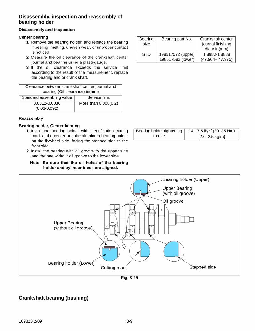
Disassembly, inspection and reassembly of bearing holderDisassembly and inspection
Center bearing1. Remove the bearing holder, and replace the bearing
if peeling, melting, uneven wear, or improper contactis noticed.
2. Measure the oil clearance of the crankshaft centerjournal and bearing using a plasti-gauge.
3. If the oil clearance exceeds the service limitaccording to the result of the measurement, replacethe bearing and/or crank shaft.
Reassembly
Bearing holder, Center bearing1. Install the bearing holder with identification cutting
mark at the center and the aluminum bearing holderon the flywheel side, facing the stepped side to thefront side.
2. Install the bearing with oil groove to the upper sideand the one without oil groove to the lower side.
Note: Be sure that the oil holes of the bearingholder and cylinder block are aligned.
Crankshaft bearing (bushing)
Clearance between crankshaft center journal and bearing (Oil clearance) in(mm)
Standard assembling value Service limit0.0012-0.0036(0.03-0.092)
More than 0.008(0.2)
Bearing size
Bearing part No. Crankshaft center journal finishing
dia ø in(mm)STD 198517572 (upper)
198517582 (lower)1.8883-1.8888
(47.964– 47.975)
Bearing holder tightening torque
14-17.5 lbf •ft(20–25 Nm) {2.0–2.5 kgfm}
Fig. 3-25
Bearing holder (Upper)
Upper Bearing(with oil groove)
Oil groove
Upper Bearing(without oil groove)
Bearing holder (Lower)Cutting mark Stepped side
109823 2/09 3-9
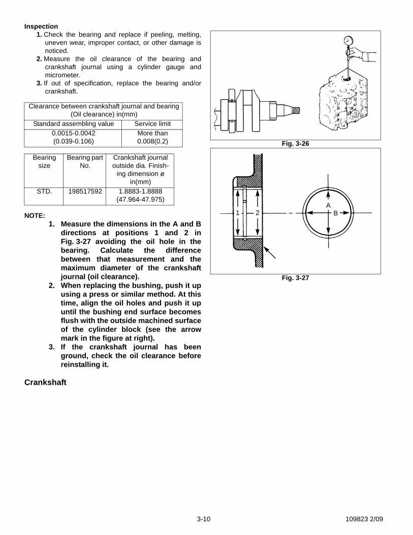
Inspection1. Check the bearing and replace if peeling, melting,
uneven wear, improper contact, or other damage isnoticed.
2. Measure the oil clearance of the bearing andcrankshaft journal using a cylinder gauge andmicrometer.
3. If out of specification, replace the bearing and/orcrankshaft.
NOTE:1. Measure the dimensions in the A and B
directions at positions 1 and 2 inFig. 3-27 avoiding the oil hole in thebearing. Calculate the differencebetween that measurement and themaximum diameter of the crankshaftjournal (oil clearance).
2. When replacing the bushing, push it upusing a press or similar method. At thistime, align the oil holes and push it upuntil the bushing end surface becomesflush with the outside machined surfaceof the cylinder block (see the arrowmark in the figure at right).
3. If the crankshaft journal has beenground, check the oil clearance beforereinstalling it.
Crankshaft
Clearance between crankshaft journal and bearing (Oil clearance) in(mm)
Standard assembling value Service limit0.0015-0.0042(0.039-0.106)
More than 0.008(0.2)
Bearing size
Bearing part No.
Crankshaft journal outside dia. Finish-
ing dimension ø in(mm)
STD. 198517592 1.8883-1.8888(47.964-47.975)
Fig. 3-26
Fig. 3-27
1 2A
B
3-10 109823 2/09
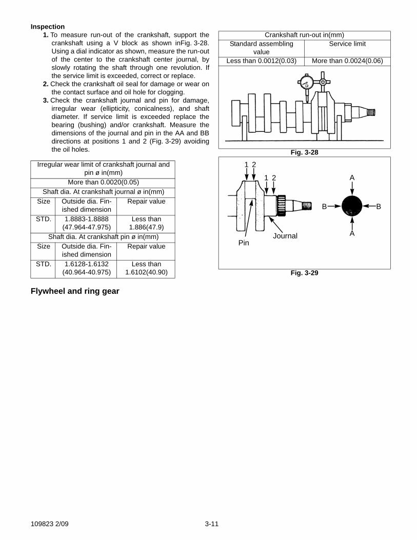
Inspection1. To measure run-out of the crankshaft, support the
crankshaft using a V block as shown inFig. 3-28.Using a dial indicator as shown, measure the run-outof the center to the crankshaft center journal, byslowly rotating the shaft through one revolution. Ifthe service limit is exceeded, correct or replace.
2. Check the crankshaft oil seal for damage or wear onthe contact surface and oil hole for clogging.
3. Check the crankshaft journal and pin for damage,irregular wear (ellipticity, conicalness), and shaftdiameter. If service limit is exceeded replace thebearing (bushing) and/or crankshaft. Measure thedimensions of the journal and pin in the AA and BBdirections at positions 1 and 2 (Fig. 3-29) avoidingthe oil holes.
Flywheel and ring gear
Irregular wear limit of crankshaft journal and pin ø in(mm)
More than 0.0020(0.05)Shaft dia. At crankshaft journal ø in(mm)
Size Outside dia. Fin-ished dimension
Repair value
STD. 1.8883-1.8888(47.964-47.975)
Less than 1.886(47.9)
Shaft dia. At crankshaft pin ø in(mm)Size Outside dia. Fin-
ished dimensionRepair value
STD. 1.6128-1.6132(40.964-40.975)
Less than 1.6102(40.90)
Crankshaft run-out in(mm)Standard assembling
valueService limit
Less than 0.0012(0.03) More than 0.0024(0.06)
Fig. 3-28
Fig. 3-29
A
B
A
B
21
21
PinJournal
109823 2/09 3-11
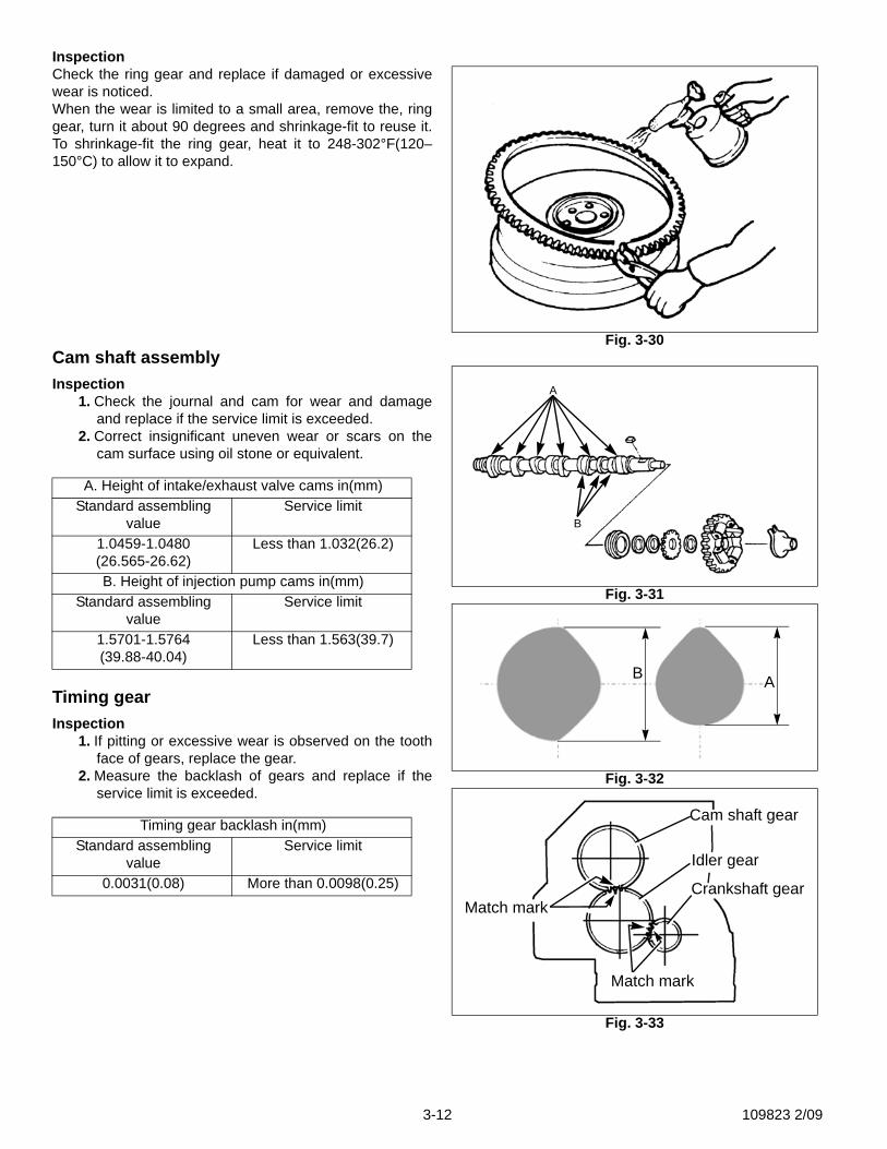
InspectionCheck the ring gear and replace if damaged or excessivewear is noticed.When the wear is limited to a small area, remove the, ringgear, turn it about 90 degrees and shrinkage-fit to reuse it.To shrinkage-fit the ring gear, heat it to 248-302°F(120–150°C) to allow it to expand.
Cam shaft assemblyInspection
1. Check the journal and cam for wear and damageand replace if the service limit is exceeded.
2. Correct insignificant uneven wear or scars on thecam surface using oil stone or equivalent.
Timing gearInspection
1. If pitting or excessive wear is observed on the toothface of gears, replace the gear.
2. Measure the backlash of gears and replace if theservice limit is exceeded.
A. Height of intake/exhaust valve cams in(mm)Standard assembling
valueService limit
1.0459-1.0480(26.565-26.62)
Less than 1.032(26.2)
B. Height of injection pump cams in(mm)Standard assembling
valueService limit
1.5701-1.5764(39.88-40.04)
Less than 1.563(39.7)
Timing gear backlash in(mm)Standard assembling
valueService limit
0.0031(0.08) More than 0.0098(0.25)
Fig. 3-30
Fig. 3-31
Fig. 3-32
Fig. 3-33
A
B
AB
Cam shaft gear
Idler gear
Crankshaft gear
Match mark
Match mark
3-12 109823 2/09
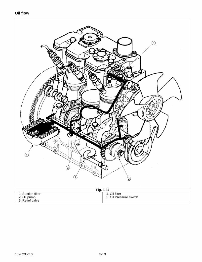
Oil flow
Fig. 3-341. Suction filter2. Oil pump3. Relief valve
4. Oil filter5. Oil Pressure switch
1 2
3
4
5
109823 2/09 3-13
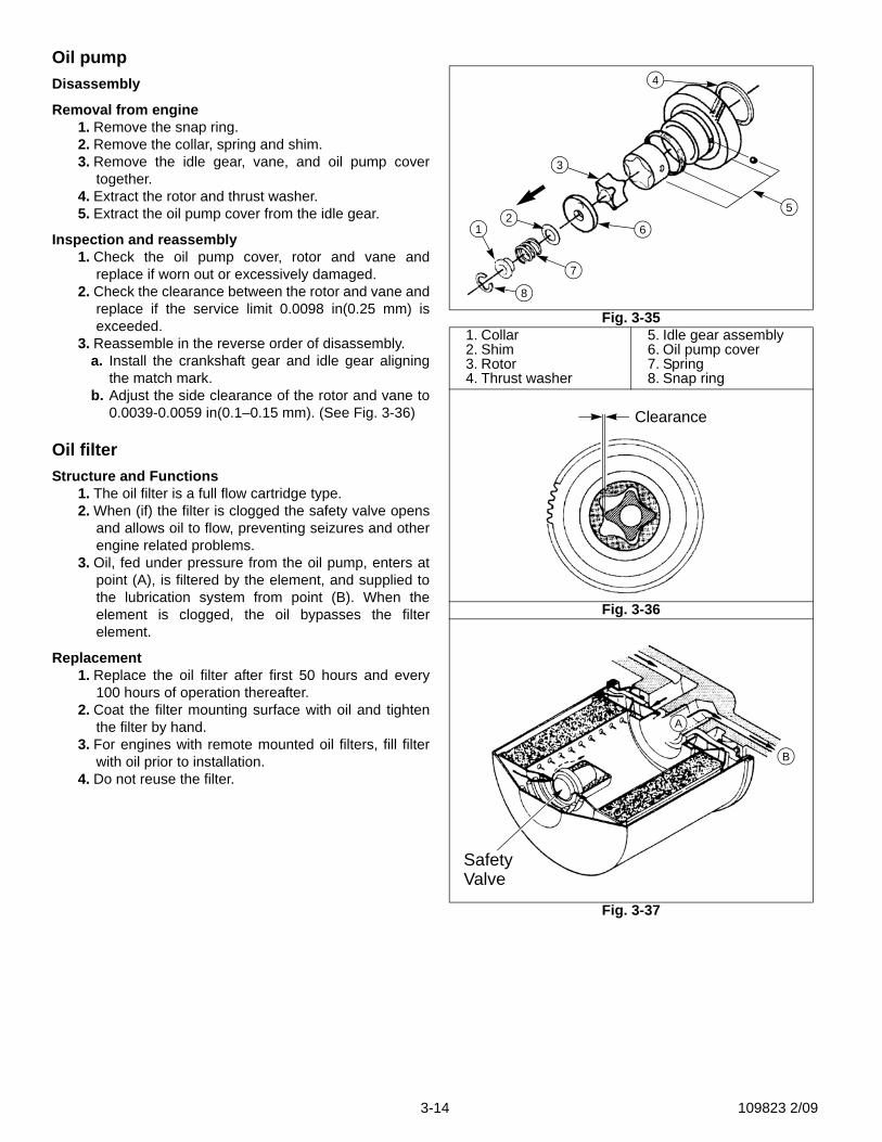
Oil pumpDisassembly
Removal from engine1. Remove the snap ring.2. Remove the collar, spring and shim.3. Remove the idle gear, vane, and oil pump cover
together.4. Extract the rotor and thrust washer.5. Extract the oil pump cover from the idle gear.
Inspection and reassembly1. Check the oil pump cover, rotor and vane and
replace if worn out or excessively damaged.2. Check the clearance between the rotor and vane and
replace if the service limit 0.0098 in(0.25 mm) isexceeded.
3. Reassemble in the reverse order of disassembly.a. Install the crankshaft gear and idle gear aligning
the match mark.b. Adjust the side clearance of the rotor and vane to
0.0039-0.0059 in(0.1–0.15 mm). (See Fig. 3-36)
Oil filterStructure and Functions
1. The oil filter is a full flow cartridge type.2. When (if) the filter is clogged the safety valve opens
and allows oil to flow, preventing seizures and otherengine related problems.
3. Oil, fed under pressure from the oil pump, enters atpoint (A), is filtered by the element, and supplied tothe lubrication system from point (B). When theelement is clogged, the oil bypasses the filterelement.
Replacement1. Replace the oil filter after first 50 hours and every
100 hours of operation thereafter.2. Coat the filter mounting surface with oil and tighten
the filter by hand.3. For engines with remote mounted oil filters, fill filter
with oil prior to installation.4. Do not reuse the filter.
Fig. 3-351. Collar2. Shim3. Rotor4. Thrust washer
5. Idle gear assembly6. Oil pump cover7. Spring8. Snap ring
Fig. 3-36
Fig. 3-37
12
3
6
5
8
4
7
Clearance
A
B
SafetyValve
3-14 109823 2/09
Water pump assembly and thermostatDisassembly and inspection
1. Remove the set plate and gasket.2. Inspect the water pump and replace if cracked, worn,
or damaged.Note: The pump main body is aluminum die cast
and should be replaced as an assembly ifthere are leaks or other problems.
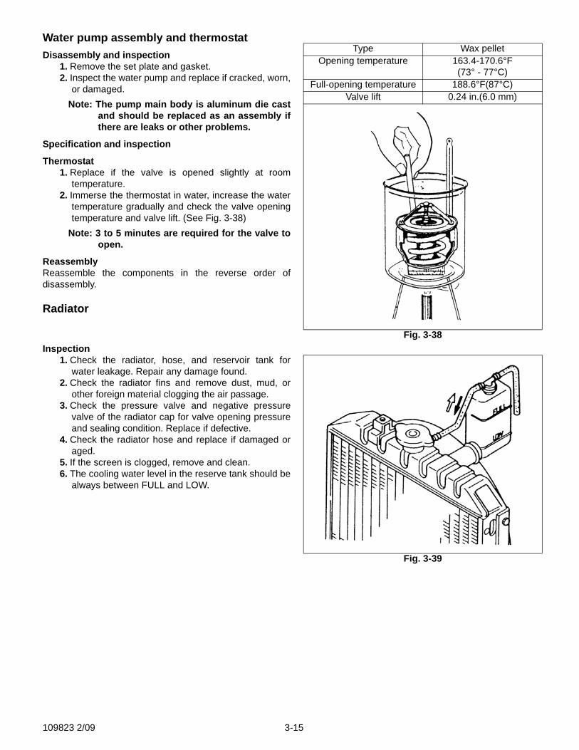
Specification and inspection
Thermostat1. Replace if the valve is opened slightly at room
temperature.2. Immerse the thermostat in water, increase the water
temperature gradually and check the valve openingtemperature and valve lift. (See Fig. 3-38)
Note: 3 to 5 minutes are required for the valve toopen.
ReassemblyReassemble the components in the reverse order ofdisassembly.
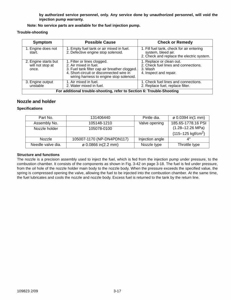
Radiator
Inspection1. Check the radiator, hose, and reservoir tank for
water leakage. Repair any damage found.2. Check the radiator fins and remove dust, mud, or
other foreign material clogging the air passage.3. Check the pressure valve and negative pressure
valve of the radiator cap for valve opening pressureand sealing condition. Replace if defective.
4. Check the radiator hose and replace if damaged oraged.
5. If the screen is clogged, remove and clean.6. The cooling water level in the reserve tank should be
always between FULL and LOW.
Type Wax pelletOpening temperature 163.4-170.6°F
(73° - 77°C)Full-opening temperature 188.6°F(87°C)
Valve lift 0.24 in.(6.0 mm)
Fig. 3-38
Fig. 3-39
109823 2/09 3-15

Fuel filterNote: N843 and N843L engines (used in the
Hustler 3500 and 3700) have an electricfuel pump.
Fuel flowThe fuel flows as shown in Fig. 3-40, from the tank,pressurized by the injection pump to high pressure, and fedto the nozzle and injected to the combustion chamber.The fuel, after lubricating the nozzle needle, is returned tothe tank through the overflow pipe.
Note: S773L engine (used in the Hustler Diesel Z)has a marine type squeeze ball locatedbetween tank and Mechanical pump.Squeeze ball us used for fuel primingpurposes
InspectionIf water, dust, or other foreign matter is observed in thesediment bowl, clean and replace the filter if necessary.
Disassembly and reassembly1. Remove the filter turning by the filter ring nut
counterclockwise.Note: Be careful not to damage the O-ring between the ring nut and main body, coat with grease before
tightening.2. Coat the area of the element to be mounted to the main body with grease and install the element by hand.
GovernorStructure and functions
1. Governor:This governor is a mechanical all-speed governor. It isinstalled in the gear case. The flyweight assembly isinstalled to the camshaft and its movement is transmitted tothe control rack of the injection pump through the slidercontrol lever link. The spring which controls the movementof the flyweight is connected to the arm COMPL andtension lever. The spring tension is changed by changingthe governor lever to control the engine speed.
2. Maximum speed set bolt:A bolt is mounted on the cylinder block. This bolt limits themovement of the arm COMPL (unloaded maximum rpm).This bolt has been adjusted and sealed at the factory.
3. Smoke set, start spring:These are built into the cylinder block to regulate the fuelinjection amount at high-speed range. Regulation of thefuel injection amount at middle speed range is made with atorque control spring to obtain higher torque.A start spring is placed between the gear case and link.This spring automatically functions to increase the amountof fuel injected when the engine is started. The smoke sethas been adjusted at the factory.
Injection pumpDisassembly, Inspection and ReassemblyDisassembly, inspection, and reassembly of injectionpump:
Note: Service of fuel injection pump is to be done
Fig. 3-401. Fuel Tank2. Mechanical fuel pump3. Nozzle and holder
4. Fuel filter5. Injection pump
41 5
2
3
Fig. 3-41
Link
Tension lever
Start Spring
Arm COMPL
3-16 109823 2/09
by authorized service personnel, only. Any service done by unauthorized personnel, will void theinjection pump warranty.
Note: No service parts are available for the fuel injection pump.
Trouble-shooting
Nozzle and holderSpecifications
Structure and functionsThe nozzle is a precision assembly used to inject the fuel, which is fed from the injection pump under pressure, to thecombustion chamber. It consists of the components as shown in Fig. 3-42 on page 3-18. The fuel is fed under pressure,from the oil hole of the nozzle holder main body to the nozzle body. When the pressure exceeds the specified value, thespring is compressed opening the valve, allowing the fuel to be injected into the combustion chamber. At the same time,the fuel lubricates and cools the nozzle and nozzle body. Excess fuel is returned to the tank by the return line.
Symptom Possible Cause Check or Remedy1. Engine does not
start.1. Empty fuel tank or air mixed in fuel.2. Defective engine stop solenoid.
1. Fill fuel tank, check for air entering system, bleed air.
2. Check and replace the electric system.2. Engine starts but
will not stop at once.
1. Filter or lines clogged.2. Air mixed in fuel.3. Fuel tank filter cap air breather clogged.4. Short-circuit or disconnected wire in
wiring harness to engine stop solenoid.
1. Replace or clean out.2. Check fuel lines and connections.3. Wash4. Inspect and repair.
3. Engine output unstable
1. Air mixed in fuel.2. Water mixed in fuel.
1. Check fuel lines and connections.2. Replace fuel, replace filter.
For additional trouble-shooting, refer to Section 6: Trouble-Shooting
Part No. 131406440 Pintle dia. ø 0.0394 in(1 mm)Assembly No. 105148-1210 Valve opening 185.65-1778.16 PSI
(1.28–12.26 MPa){115–125 kgf/cm2}
Nozzle holder 105078-0100
Nozzle 105007-1170 (NP-DN4PDN117) Injection angle 4°Needle valve dia. ø 0.0866 in(2.2 mm) Nozzle type Throttle type
109823 2/09 3-17

Disassembly and inspection1. Place the nozzle holder (body) in a vise and
disassemble turning the nozzle nut.Note: Be careful not to drop the needle valve
when removing the nozzle.2. Wash the nozzle and needle valve and check for
seizure and sticking in the nozzle, and fuel leakageon the seat surface. Correct fuel leakage by lappingthe seat.
3. Check the nozzle spacer for defects; it must sealagainst the nozzle body holder and the nozzle body.
4. Check the push rod for wear on the nozzle needlevalve contact surface and check the spring seat forcracks.
Reassembly and adjustment1. When assembling a new nozzle assembly, heat light
oil to 122-140°F(50–60°C) and remove the rustpreventative from it for use in a nozzle tester.
2. Slide the needle valve into the nozzle body withoutthe spring and shims, to ensure that they slideeasily.
3. Invert the nozzle body; place the shim(s), spring,needle valve, spacer and nozzle on the nozzle bodyin this order. Install nozzle nut and tighten.
4. After assembly, check nozzle injection pressure.a. Adjust by the adjusting shims so that the injection
is started at 1707.1 PSI (11.77 MPa) {120 kgf/cm2}on all models.
b. The pressure increases or decreases about 142.1PSI (0.98 MPa) {10 kgf/cm2} for shims of 0.00340in(0.1 mm) thickness.
5. Injection conditiona. Small drops should not be mixed in the spray.b. The injection pattern should be conical in shape.c. Place white paper at about 11.8 in.(30 cm) from
the nozzle and confirm that the spray isapproximately circular when injected.
d. Lower the pressure 284.3 PSI (1.96 MPa) {20 kgf/cm2} from the specified value of 1707.1 PSI (11.77Mpa) {120 kgf/cm2} and check that the test oildoes not drip from the nozzle end.
Fig. 3-421. Nut2. Nozzle3. Nozzle body4. Shim
5. Spring6. Needle valve7. Spacer8. Nozzle nut
Fig. 3-43
1
3
4}
5
67
8
2
1
3
45
67
Valve Closed Valve openfully opened(main injection)
Fig. 3-441. Gasket2. Nozzle nut; Torque:
21.7-36.2 lbf •ft (3-5 kgf•m)
3. Nozzle4. Nozzle spacer5. Needle valve
6. Spring7. Shim8. Nozzle body9. Nut; Torque: 21.7-29.3
lbf •ft (3-4 kgf•m)
1
223
45
67
8
9
3-18 109823 2/09

SECTION 4: ENGINE RE-ASSEMBLY
Caution: before assembling engine;
1. Clean parts to be installed. (Especially oil passages, bearings, pistons, and cylinder borescarefully.)
2. Coat the sliding and rotating parts of the cylinder bore, piston, bearing and other parts withnew oil before installing.
3. Use new gaskets. If necessary, use gasket sealants to prevent oil leakage.4. Do not tighten bolts and nuts for aluminum alloy parts excessively. Tighten them to speci-
fied torque.
Relief valve assembly with O-Ring.Relief valve, torque to:
41.3-48.3 lbf •ft (59–69 N·m) {6.0–7.0 kgf·m}
Crank shaft and bearing holder assemblyCylinder block to bearing holder torque
Notes: 1. Be careful not to damage the bushing in thecylinder block by the crankshaft gear wheninstall the crankshaft and bearing holderassembly.
2. Install the two hexagon socket head boltsfor the flywheel side bearing holder.
Measure the end play of crankshaft.
Relief valve torque43.5-50.9 lbf•ft (59-69 N·m) {6.0-7.0 kgf·m}
Bearing holder boltsA Hexagon socket
head bolt17.5-20.3 lbf•ft (25–29 N·m)
{2.5–3.0 kgf·m}B Hexagon bolt 17.5-20.3 lbf•ft (25–29 N·m)
{2.5–3.0 kgf·m}
Crankshaft end playStandard value 0.004-0.012 (0.1–0.3)
Service limit More than 0.020(0.5)
Fig. 4-1
B
A
Fig. 4-2
109823 2/09 4-1
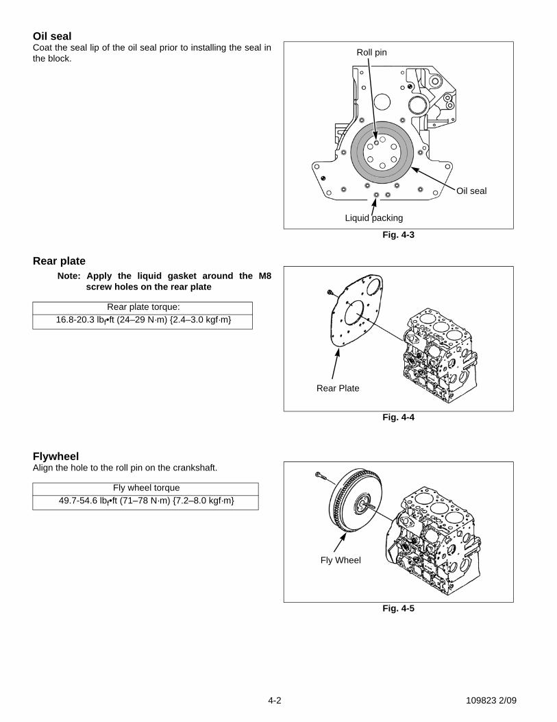
Oil sealCoat the seal lip of the oil seal prior to installing the seal inthe block.
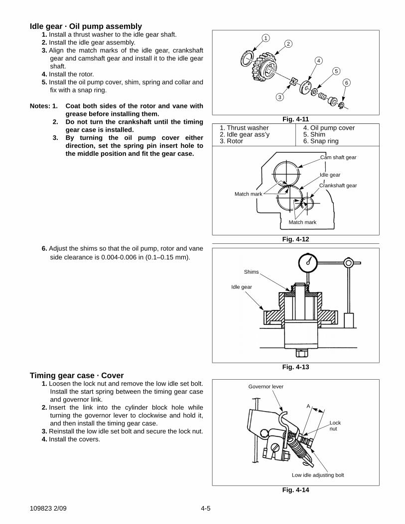
Rear plateNote: Apply the liquid gasket around the M8
screw holes on the rear plate
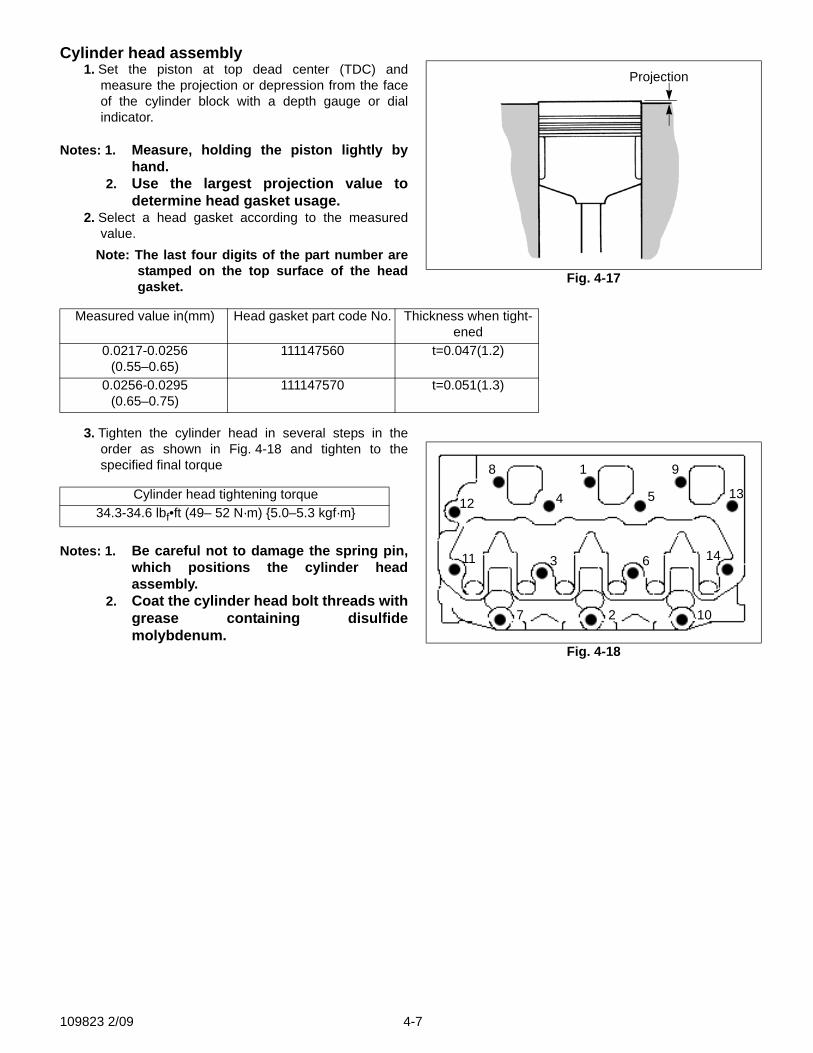
FlywheelAlign the hole to the roll pin on the crankshaft.
Rear plate torque:16.8-20.3 lbf•ft (24–29 N·m) {2.4–3.0 kgf·m}
Fly wheel torque49.7-54.6 lbf•ft (71–78 N·m) {7.2–8.0 kgf·m}
Fig. 4-3
Roll pin
Liquid packing
Oil seal
Fig. 4-4
Rear Plate
Fig. 4-5
Fly Wheel
4-2 109823 2/09

Piston and connecting rod assembly1. Coat the metal surface, piston and piston ring with
engine oil.2. Turn the ring to distribute the oil in the ring groove,
and set the ring end gaps at 90° respectivelyavoiding piston pin direction and the direction at aright angle to the piston pin.
3. Insert the ring facing the connecting rod figure matchmark toward the injection pump side, using ringpliers.
Note: Place the smallest connecting rod figurematch mark to the front cylinder positionso that the figures increase toward the rearof the engine.
4. Tighten the connecting rod cap with the specifiedtorque and check for the axial play.
Notes: 1. After tightening, verify that the crankshaftmoves easily.
2. The connecting rod should move 0.004-.012in (0.1–0.3 mm) in the axial direction.
Suction pipe · Suction filter1. Install an O-Ring on the suction pipe and insert the
suction pipe into the cylinder block.2. Place the suction pipe end into the suction filter and
fasten the suction filter.
Connecting rod torque20.3-23.8 lbf•ft (29–34 N·m) {3.0–3.5 kgf·m}
Suction filter torque79.7-115.1 lbf•in (9–13 N·m) {0.9–1.3 kgf·m}
Fig. 4-6
Fig. 4-7
Oil
Oil
Injection pump side
Fig. 4-8
Suction pump
Suction filter
109823 2/09 4-3

Oil panStart tightening the bolts of the oil pan from the center, thentighten the opposing bolt on opposite side on the diagonaland to specified torque. (See Fig. 4-9).
Oil dipstick · Dipstick guideInstall the oil level gauge and gauge guide using two O-Rings.
Front plateInstall the front plate together with the gasket.
Camshaft assembly · Tachometer shaft plate1. Install the tachometer shaft.2. Install the cam shaft assembly (be careful with the
bearing).3. Fix the tachometer shaft and cam shaft assembly
with the plate.
Note: When installing the timing gear case, alignthe notch in the slider with the guide pin.
Bolt torque7.4-9.6 lbf•ft (10–13 N·m) {1.0–1.3kgf·m}
Plate torque79.7-115.1 lbf•in (9–13 N·m) {0.9-1.3 kgf·m}
Fig. 4-9
Fig. 4-10
141721 19
7
10
12
13
21
20
18
16
23
25
26 1 9 11152224
82 4 6
5
3
Guide pin
Slider
Camshaft
Idler gear
Plate
4-4 109823 2/09
Idle gear · Oil pump assembly1. Install a thrust washer to the idle gear shaft.2. Install the idle gear assembly.3. Align the match marks of the idle gear, crankshaft
gear and camshaft gear and install it to the idle gearshaft.
4. Install the rotor.5. Install the oil pump cover, shim, spring and collar and
fix with a snap ring.
Notes: 1. Coat both sides of the rotor and vane withgrease before installing them.
2. Do not turn the crankshaft until the timinggear case is installed.
3. By turning the oil pump cover eitherdirection, set the spring pin insert hole tothe middle position and fit the gear case.
6. Adjust the shims so that the oil pump, rotor and vaneside clearance is 0.004-0.006 in (0.1–0.15 mm).
Timing gear case · Cover1. Loosen the lock nut and remove the low idle set bolt.
Install the start spring between the timing gear caseand governor link.
2. Insert the link into the cylinder block hole whileturning the governor lever to clockwise and hold it,and then install the timing gear case.
3. Reinstall the low idle set bolt and secure the lock nut.4. Install the covers.
Fig. 4-111. Thrust washer2. Idle gear ass’y3. Rotor
4. Oil pump cover5. Shim6. Snap ring
Fig. 4-12
12
3
4
5
6
Cam shaft gear
Idle gear
Crankshaft gearMatch mark
Match mark
Fig. 4-13
Shims
Idle gear
Fig. 4-14
Governor lever
Lock
Low idle adjusting bolt
A
nut
109823 2/09 4-5

Crankshaft pulleyInstall the key into the crankshaft, and install the crankshaftpulley and tighten with the nut.
Injection pump assembly1. Install the shim, which was removed during
disassembly, connect the control rack of the injectionpump and link, and install the snap pin.
2. Tighten the injection pump bolts and nuts.
Notes: 1. When shim is not required, use a lightcoat of silicone before installing.
2. The injection timing varies about 2ºwith 0.012in (0.3 mm) of shims.
3. Use a combination of shims (0.020 in(0.5 mm)) with beading and a shim(0.020 in (0.5 mm)) without beadingwhen you need adjusting shims morethan 0.0394 in (1.0 mm).
‘Oil filterCoat the mounting surface with a small quantity of oil andtighten by hand.
Engine stop solenoidTighten the engine stop solenoid lightly with pliers.
Crankshaft pulley torque82.6-88.9 lbf•ft (118–127 N·m) {12–13 kgf·m}
Injection pump torque73.47-100.0 in•lbf (8.3–11.3 N·m) {0.85–11.5 kgf·m}
Injection timing adjusting shimThickness in(mm) Part code
0.008 (0.2) 1314375900.012 (0.3) 1314376000.016 (0.4) 1314376100.020 (0.5) 1314376200.020 (0.5) *131437630
* Without beading
Fig. 4-15
Fig. 4-16
Snap pin
Injection pump
Shim
Link
4-6 109823 2/09
Cylinder head assembly1. Set the piston at top dead center (TDC) and
measure the projection or depression from the faceof the cylinder block with a depth gauge or dialindicator.
Notes: 1. Measure, holding the piston lightly byhand.
2. Use the largest projection value todetermine head gasket usage.
2. Select a head gasket according to the measuredvalue.
Note: The last four digits of the part number arestamped on the top surface of the headgasket.
3. Tighten the cylinder head in several steps in theorder as shown in Fig. 4-18 and tighten to thespecified final torque
Notes: 1. Be careful not to damage the spring pin,which positions the cylinder headassembly.
2. Coat the cylinder head bolt threads withgrease containing disulfidemolybdenum.
Measured value in(mm) Head gasket part code No. Thickness when tight-ened
0.0217-0.0256(0.55–0.65)
111147560 t=0.047(1.2)
0.0256-0.0295(0.65–0.75)
111147570 t=0.051(1.3)
Cylinder head tightening torque34.3-34.6 lbf•ft (49– 52 N·m) {5.0–5.3 kgf·m}
Fig. 4-17
Projection
Fig. 4-18
1
2
3
4 5
6
7
8 9
10
11
1213
14
109823 2/09 4-7
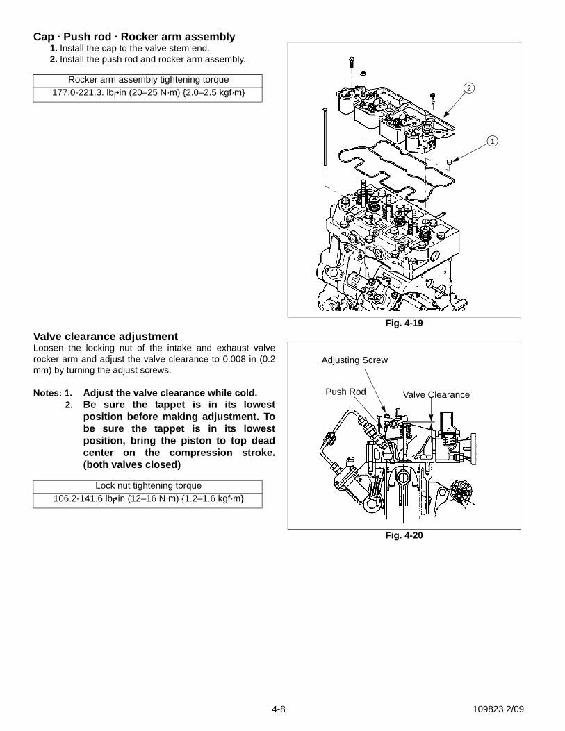
Cap · Push rod · Rocker arm assembly1. Install the cap to the valve stem end.2. Install the push rod and rocker arm assembly.
Valve clearance adjustmentLoosen the locking nut of the intake and exhaust valverocker arm and adjust the valve clearance to 0.008 in (0.2mm) by turning the adjust screws.
Notes: 1. Adjust the valve clearance while cold.2. Be sure the tappet is in its lowest
position before making adjustment. Tobe sure the tappet is in its lowestposition, bring the piston to top deadcenter on the compression stroke.(both valves closed)
Rocker arm assembly tightening torque177.0-221.3. lbf•in (20–25 N·m) {2.0–2.5 kgf·m}
Lock nut tightening torque106.2-141.6 lbf•in (12–16 N·m) {1.2–1.6 kgf·m}
Fig. 4-19
1
2
Fig. 4-20
Adjusting Screw
Push Rod Valve Clearance
4-8 109823 2/09
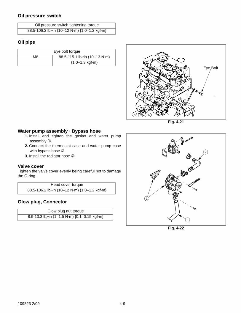
Oil pressure switch
Oil pipe
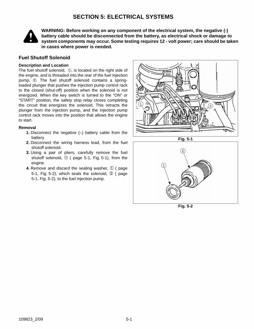
Water pump assembly · Bypass hose1. Install and tighten the gasket and water pump
assembly ➀.2. Connect the thermostat case and water pump case
with bypass hose ➁.3. Install the radiator hose ➂.
Valve coverTighten the valve cover evenly being careful not to damagethe O-ring.
Glow plug, Connector
Oil pressure switch tightening torque88.5-106.2 lbf•in (10–12 N·m) {1.0–1.2 kgf·m}
Eye bolt torqueM8 88.5-115.1 lbf•in (10–13 N·m)
{1.0–1.3 kgf·m}
Head cover torque88.5-106.2 lbf•in (10–12 N·m) {1.0–1.2 kgf·m}
Glow plug nut torque8.9-13.3 lbf•in (1–1.5 N·m) {0.1–0.15 kgf·m}
Fig. 4-21
Eye Bolt
Fig. 4-22
2
1
3
109823 2/09 4-9

109823 2/09 4-16
SECTION 5: ELECTRICAL SYSTEMS
WARNING: Before working on any component of the electrical system, the negative (-) battery cable should be disconnected from the battery, as electrical shock or damage to system components may occur. Some testing requires 12 - volt power; care should be taken in cases where power is needed.
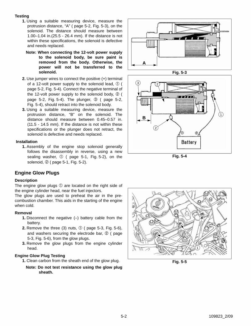
Fuel Shutoff SolenoidDescription and LocationThe fuel shutoff solenoid, , is located on the right side ofthe engine, and is threaded into the rear of the fuel injectionpump, . The fuel shutoff solenoid contains a spring-loaded plunger that pushes the injection pump control rackto the closed (shut-off) position when the solenoid is notenergized. When the key switch is turned to the “ON” or“START” position, the safety stop relay closes completingthe circuit that energizes the solenoid. This retracts theplunger from the injection pump, and the injection pumpcontrol rack moves into the position that allows the engineto start.
Removal1. Disconnect the negative (–) battery cable from the
battery.2. Disconnect the wiring harness lead, from the fuel
shutoff solenoid.3. Using a pair of pliers, carefully remove the fuel
shutoff solenoid, ( page 5-1, Fig. 5-1), from theengine.
4. Remove and discard the sealing washer, ( page5-1, Fig. 5-2), which seals the solenoid, ( page5-1, Fig. 5-2), to the fuel injection pump.
Fig. 5-1
Fig. 5-2
21
2
1
109823_2/09 5-1
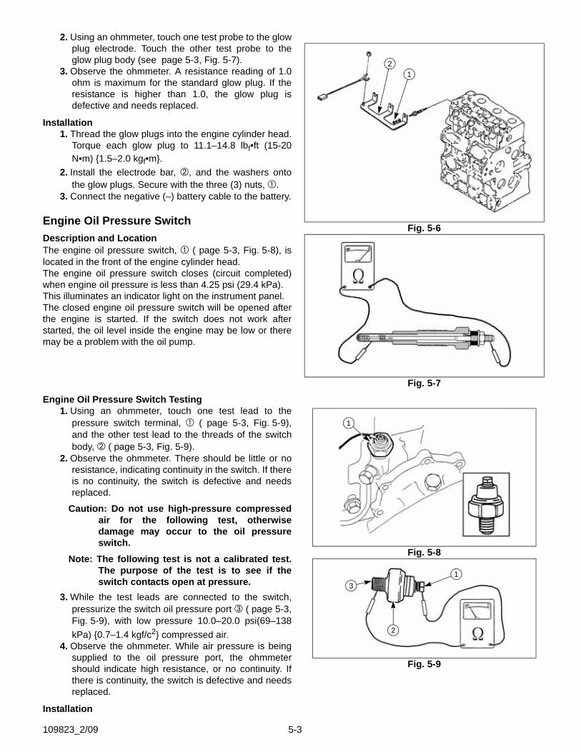
Testing1. Using a suitable measuring device, measure the
protrusion distance, “A” ( page 5-2, Fig. 5-3), on thesolenoid. The distance should measure between1.00–1.04 in.(25.5 - 26.4 mm). If the distance is notwithin these specifications, the solenoid is defectiveand needs replaced.
Note: When connecting the 12-volt power supplyto the solenoid body, be sure paint isremoved from the body. Otherwise, thepower will not be transferred to thesolenoid.
2. Use jumper wires to connect the positive (+) terminalof a 12-volt power supply to the solenoid lead, (page 5-2, Fig. 5-4). Connect the negative terminal ofthe 12-volt power supply to the solenoid body, (page 5-2, Fig. 5-4). The plunger, ( page 5-2,Fig. 5-4), should retract into the solenoid body.
3. Using a suitable measuring device, measure theprotrusion distance, “B” on the solenoid. Thedistance should measure between 0.45–0.57 in.(11.5 - 14.5 mm). If the distance is not within thesespecifications or the plunger does not retract, thesolenoid is defective and needs replaced.
Installation1. Assembly of the engine stop solenoid generally
follows the disassembly in reverse, using a newsealing washer, ( page 5-1, Fig. 5-2), on thesolenoid, ( page 5-1, Fig. 5-2).
Engine Glow PlugsDescriptionThe engine glow plugs are located on the right side ofthe engine cylinder head, near the fuel injectors.The glow plugs are used to preheat the air in the pre-combustion chamber. This aids in the starting of the enginewhen cold.
Removal1. Disconnect the negative (–) battery cable from the
battery.2. Remove the three (3) nuts, ( page 5-3, Fig. 5-6),
and washers securing the electrode bar, ( page5-3, Fig. 5-6), from the glow plugs.
3. Remove the glow plugs from the engine cylinderhead.
Engine Glow Plug Testing1. Clean carbon from the sheath end of the glow plug.
Note: Do not test resistance using the glow plugsheath.
Fig. 5-3
Fig. 5-4
A
2
1
23
2
B
Fig. 5-5
1
5-2 109823_2/09
2. Using an ohmmeter, touch one test probe to the glowplug electrode. Touch the other test probe to theglow plug body (see page 5-3, Fig. 5-7).
3. Observe the ohmmeter. A resistance reading of 1.0ohm is maximum for the standard glow plug. If theresistance is higher than 1.0, the glow plug isdefective and needs replaced.
Installation1. Thread the glow plugs into the engine cylinder head.
Torque each glow plug to 11.1–14.8 lbf•ft (15-20N•m) {1.5–2.0 kgf•m}.
2. Install the electrode bar, , and the washers ontothe glow plugs. Secure with the three (3) nuts, .
3. Connect the negative (–) battery cable to the battery.
Engine Oil Pressure SwitchDescription and LocationThe engine oil pressure switch, ( page 5-3, Fig. 5-8), islocated in the front of the engine cylinder head.The engine oil pressure switch closes (circuit completed)when engine oil pressure is less than 4.25 psi (29.4 kPa).This illuminates an indicator light on the instrument panel.The closed engine oil pressure switch will be opened afterthe engine is started. If the switch does not work afterstarted, the oil level inside the engine may be low or theremay be a problem with the oil pump.
Engine Oil Pressure Switch Testing1. Using an ohmmeter, touch one test lead to the
pressure switch terminal, ( page 5-3, Fig. 5-9),and the other test lead to the threads of the switchbody, ( page 5-3, Fig. 5-9).
2. Observe the ohmmeter. There should be little or noresistance, indicating continuity in the switch. If thereis no continuity, the switch is defective and needsreplaced.
Caution: Do not use high-pressure compressedair for the following test, otherwisedamage may occur to the oil pressureswitch.
Note: The following test is not a calibrated test.The purpose of the test is to see if theswitch contacts open at pressure.
3. While the test leads are connected to the switch,pressurize the switch oil pressure port ( page 5-3,Fig. 5-9), with low pressure 10.0–20.0 psi(69–138kPa) {0.7–1.4 kgf/c2} compressed air.
4. Observe the ohmmeter. While air pressure is beingsupplied to the oil pressure port, the ohmmetershould indicate high resistance, or no continuity. Ifthere is continuity, the switch is defective and needsreplaced.
Installation
Fig. 5-6
Fig. 5-7
12
Fig. 5-8
Fig. 5-9
1
1
2
3
109823_2/09 5-3
1. Install the oil pressure switch into the engine cylinder head and tighten to 10.8–14.4 lbf•ft(14.7–19.6 N•m) (1.5–2.0kgf•m).
2. Install the ring terminal onto the oil pressure switch, and secure the terminal with the retaining screw, , ( page5-3, Fig. 5-9).
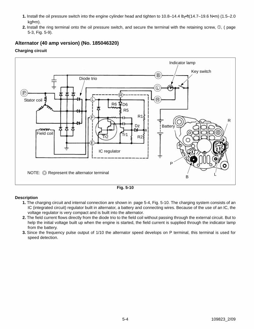
Alternator (40 amp version) (No. 185046320)Charging circuit
Description1. The charging circuit and internal connection are shown in page 5-4, Fig. 5-10. The charging system consists of an
IC (integrated circuit) regulator built in alternator, a battery and connecting wires. Because of the use of an IC, thevoltage regulator is very compact and is built into the alternator.
2. The field current flows directly from the diode trio to the field coil without passing through the external circuit. But tohelp the initial voltage built up when the engine is started, the field current is supplied through the indicator lampfrom the battery.
3. Since the frequency pulse output of 1/10 the alternator speed develops on P terminal, this terminal is used forspeed detection.
Fig. 5-10
NOTE: Represent the alternator terminal
P
B
L
RR
L
F
E
Stator coil
Field coil
IC regulator
Diode trio
Indicator lamp
BatteryR
LB
P
R1
R6
R2Tr2 Tr1
R5D6
Dz
Key switch
a
5-4 109823_2/09
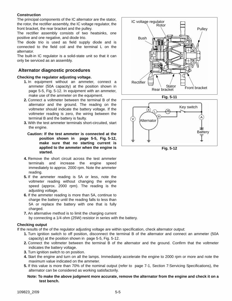
ConstructionThe principal components of the IC alternator are the stator,the rotor, the rectifier assembly, the IC voltage regulator, thefront bracket, the rear bracket and the pulley.The rectifier assembly consists of two heatsinks, onepositive and one negative, and diode trio.The diode trio is used as field supply diode and isconnected to the field coil and the terminal L on thealternator.The built-in IC regulator is a solid-state unit so that it canonly be serviced as an assembly.
Alternator diagnostic proceduresChecking the regulator adjusting voltage.
1. In equipment without an ammeter, connect aammeter (50A capacity) at the position shown inpage 5-5, Fig. 5-12. In equipment with an ammeter,make use of the ammeter on the equipment.
2. Connect a voltmeter between the terminal B of thealternator and the ground. The reading on thevoltmeter should indicate the battery voltage. If thevoltmeter reading is zero, the wiring between theterminal B and the battery is faulty.
3. With the test ammeter terminals short-circuited, startthe engine.
Caution: If the test ammeter is connected at theposition shown in page 5-5, Fig. 5-12,make sure that no starting current isapplied to the ammeter when the engine isstarted.
4. Remove the short circuit across the test ammeterterminals and increase the engine speedimmediately to approx. 2000 rpm. Note the ammeterreading.
5. If the ammeter reading is 5A or less, note thevoltmeter reading without changing the enginespeed (approx. 2000 rpm). The reading is theadjusting voltage.
6. If the ammeter reading is more than 5A, continue tocharge the battery until the reading falls to less than5A or replace the battery with one that is fullycharged.
7. An alternative method is to limit the charging currentby connecting a 1/4 ohm (25W) resistor in series with the battery.
Checking outputIf the results of the of the regulator adjusting voltage are within specification, check alternator output:
1. Turn ignition switch to off position, disconnect the terminal B of the alternator and connect an ammeter (50Acapacity) at the position shown in page 5-5, Fig. 5-12.
2. Connect the voltmeter between the terminal B of the alternator and the ground. Confirm that the voltmeterindicates the battery voltage.
3. Turn ignition switch to on position.4. Start the engine and turn on all the lamps. Immediately accelerate the engine to 2000 rpm or more and note the
maximum value indicated on the ammeter.5. If this value is more than 70% of the nominal output (refer to page 7-1, Section 7:Servicing Specifications), the
alternator can be considered as working satisfactorily.Note: To make the above judgment more accurate, remove the alternator from the engine and check it on a
test bench.
Fig. 5-11
Fig. 5-12
RotorIC voltage regulator
Pulley
Bush
Stator Front bracketRear bracket
Rectifier
V
B L
R A
Battery
Key switch
Alternator
109823_2/09 5-5
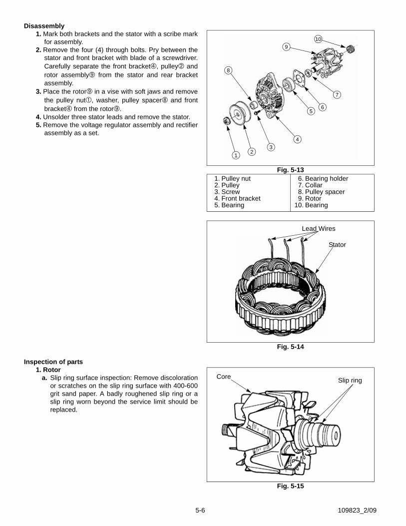
Disassembly1. Mark both brackets and the stator with a scribe mark
for assembly.2. Remove the four (4) through bolts. Pry between the
stator and front bracket with blade of a screwdriver.Carefully separate the front bracket , pulley androtor assembly from the stator and rear bracketassembly.
3. Place the rotor in a vise with soft jaws and removethe pulley nut , washer, pulley spacer and frontbracket from the rotor .
4. Unsolder three stator leads and remove the stator.5. Remove the voltage regulator assembly and rectifier
assembly as a set.
Inspection of parts1. Rotor
a. Slip ring surface inspection: Remove discolorationor scratches on the slip ring surface with 400-600grit sand paper. A badly roughened slip ring or aslip ring worn beyond the service limit should bereplaced.
Fig. 5-131. Pulley nut2. Pulley3. Screw4. Front bracket5. Bearing
6. Bearing holder7. Collar8. Pulley spacer9. Rotor
10. Bearing
Fig. 5-14
1 23
4
6
7
109
8
5
Lead Wires
Stator
Fig. 5-15
Core Slip ring
5-6 109823_2/09
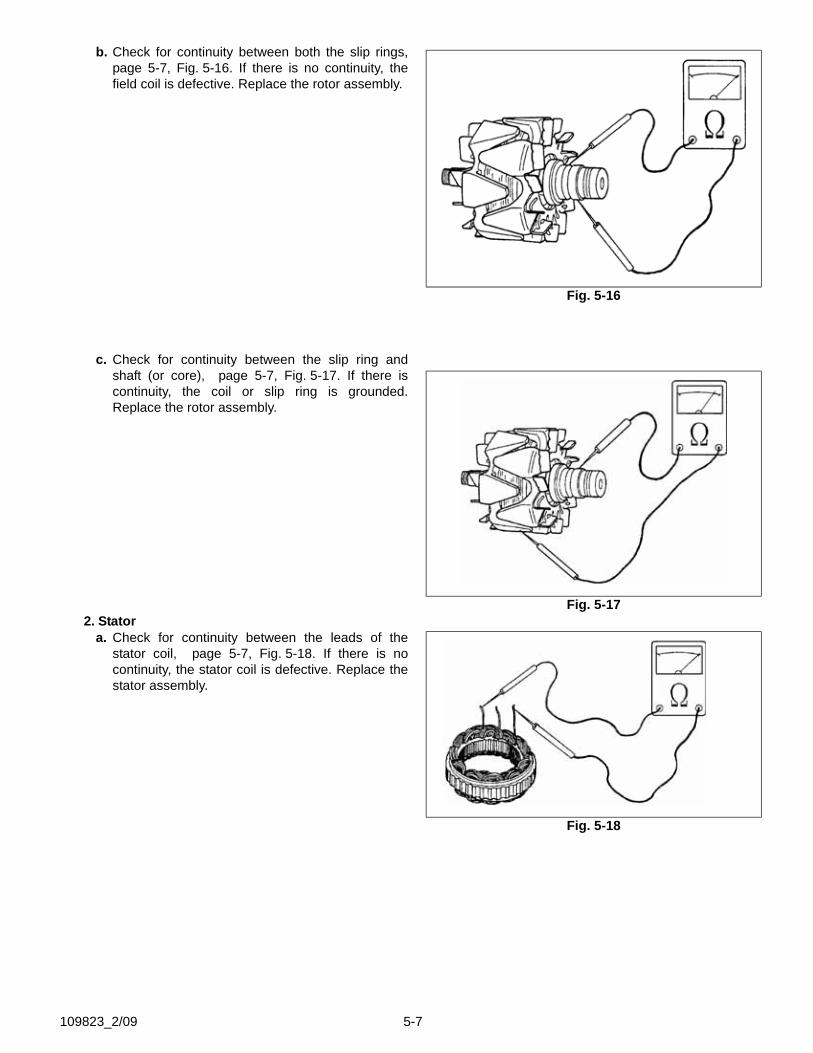
b. Check for continuity between both the slip rings,page 5-7, Fig. 5-16. If there is no continuity, thefield coil is defective. Replace the rotor assembly.
c. Check for continuity between the slip ring andshaft (or core), page 5-7, Fig. 5-17. If there iscontinuity, the coil or slip ring is grounded.Replace the rotor assembly.
2. Statora. Check for continuity between the leads of the
stator coil, page 5-7, Fig. 5-18. If there is nocontinuity, the stator coil is defective. Replace thestator assembly.
Fig. 5-16
Fig. 5-17
Fig. 5-18
109823_2/09 5-7
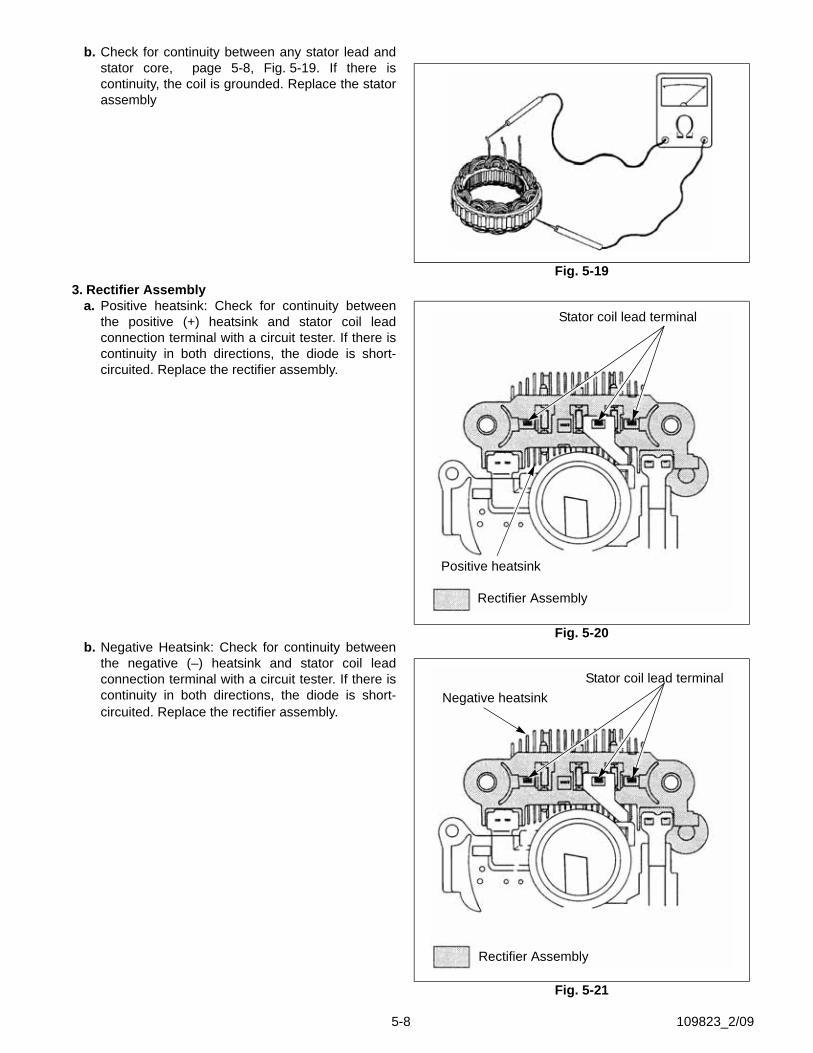
b. Check for continuity between any stator lead andstator core, page 5-8, Fig. 5-19. If there iscontinuity, the coil is grounded. Replace the statorassembly
3. Rectifier Assemblya. Positive heatsink: Check for continuity between
the positive (+) heatsink and stator coil leadconnection terminal with a circuit tester. If there iscontinuity in both directions, the diode is short-circuited. Replace the rectifier assembly.
b. Negative Heatsink: Check for continuity betweenthe negative (–) heatsink and stator coil leadconnection terminal with a circuit tester. If there iscontinuity in both directions, the diode is short-circuited. Replace the rectifier assembly.
Fig. 5-19
Fig. 5-20
Stator coil lead terminal
Positive heatsink
Rectifier Assembly
Fig. 5-21
Stator coil lead terminalNegative heatsink
Rectifier Assembly
5-8 109823_2/09
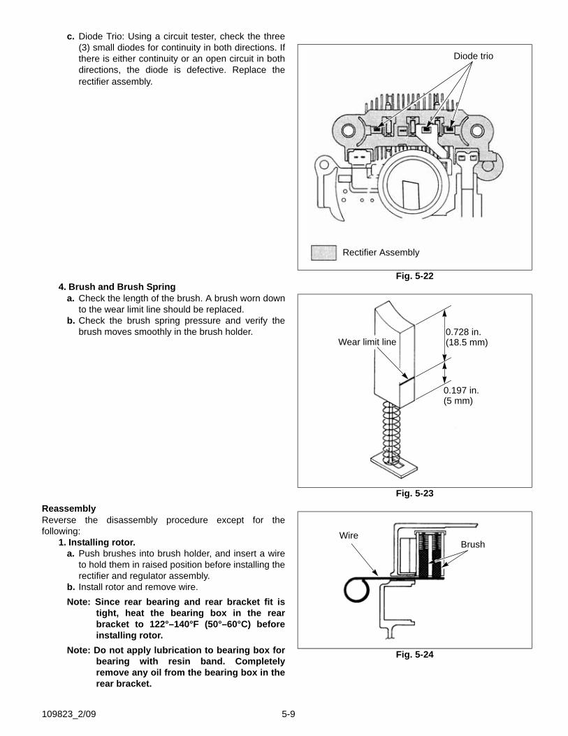
c. Diode Trio: Using a circuit tester, check the three(3) small diodes for continuity in both directions. Ifthere is either continuity or an open circuit in bothdirections, the diode is defective. Replace therectifier assembly.
4. Brush and Brush Springa. Check the length of the brush. A brush worn down
to the wear limit line should be replaced.b. Check the brush spring pressure and verify the
brush moves smoothly in the brush holder.
ReassemblyReverse the disassembly procedure except for thefollowing:
1. Installing rotor.a. Push brushes into brush holder, and insert a wire
to hold them in raised position before installing therectifier and regulator assembly.
b. Install rotor and remove wire.Note: Since rear bearing and rear bracket fit is
tight, heat the bearing box in the rearbracket to 122°–140°F (50°–60°C) beforeinstalling rotor.
Note: Do not apply lubrication to bearing box forbearing with resin band. Completelyremove any oil from the bearing box in therear bracket.
Fig. 5-22
Diode trio
Rectifier Assembly
Fig. 5-23
0.728 in.(18.5 mm)
0.197 in.(5 mm)
Wear limit line
Fig. 5-24
BrushWire
109823_2/09 5-9
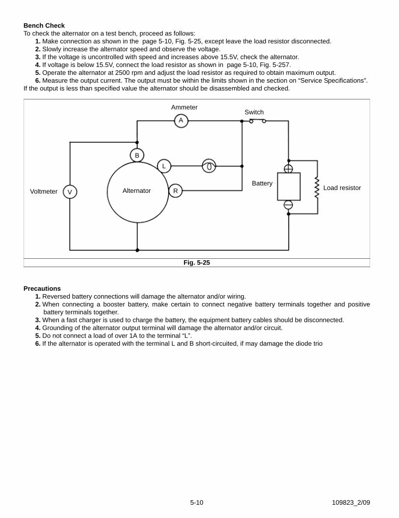
Bench CheckTo check the alternator on a test bench, proceed as follows:
1. Make connection as shown in the page 5-10, Fig. 5-25, except leave the load resistor disconnected.2. Slowly increase the alternator speed and observe the voltage.3. If the voltage is uncontrolled with speed and increases above 15.5V, check the alternator.4. If voltage is below 15.5V, connect the load resistor as shown in page 5-10, Fig. 5-257.5. Operate the alternator at 2500 rpm and adjust the load resistor as required to obtain maximum output.6. Measure the output current. The output must be within the limits shown in the section on “Service Specifications”.
If the output is less than specified value the alternator should be disassembled and checked.
Precautions1. Reversed battery connections will damage the alternator and/or wiring.2. When connecting a booster battery, make certain to connect negative battery terminals together and positive
battery terminals together.3. When a fast charger is used to charge the battery, the equipment battery cables should be disconnected.4. Grounding of the alternator output terminal will damage the alternator and/or circuit.5. Do not connect a load of over 1A to the terminal “L”.6. If the alternator is operated with the terminal L and B short-circuited, if may damage the diode trio
Fig. 5-25
Voltmeter
AmmeterSwitch
Load resistorBattery
AlternatorV
B
A
L
R
5-10 109823_2/09
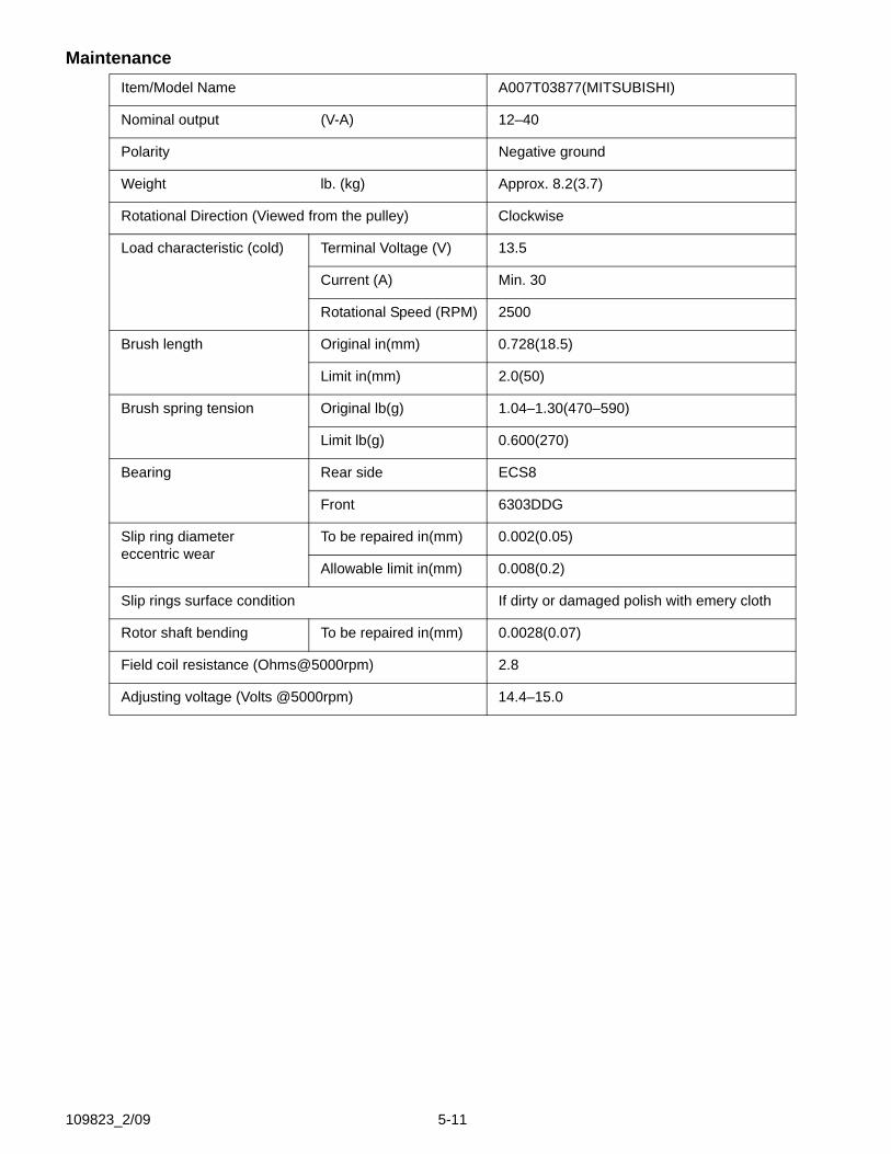
MaintenanceItem/Model Name A007T03877(MITSUBISHI)
Nominal output (V-A) 12–40
Polarity Negative ground
Weight lb. (kg) Approx. 8.2(3.7)
Rotational Direction (Viewed from the pulley) Clockwise
Load characteristic (cold) Terminal Voltage (V) 13.5
Current (A) Min. 30
Rotational Speed (RPM) 2500
Brush length Original in(mm) 0.728(18.5)
Limit in(mm) 2.0(50)
Brush spring tension Original lb(g) 1.04–1.30(470–590)
Limit lb(g) 0.600(270)
Bearing Rear side ECS8
Front 6303DDG
Slip ring diametereccentric wear
To be repaired in(mm) 0.002(0.05)
Allowable limit in(mm) 0.008(0.2)
Slip rings surface condition If dirty or damaged polish with emery cloth
Rotor shaft bending To be repaired in(mm) 0.0028(0.07)
Field coil resistance (Ohms@5000rpm) 2.8
Adjusting voltage (Volts @5000rpm) 14.4–15.0
109823_2/09 5-11
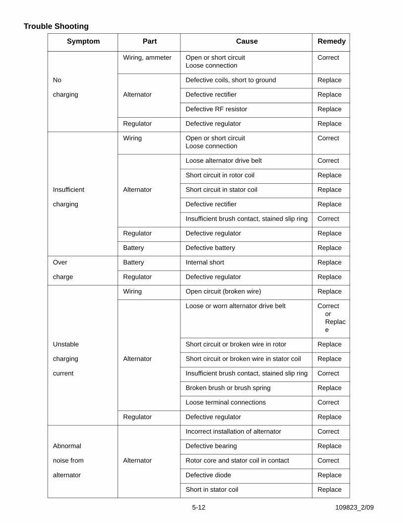
Trouble Shooting
Symptom Part Cause Remedy
Wiring, ammeter Open or short circuitLoose connection
Correct
No Defective coils, short to ground Replace
charging Alternator Defective rectifier Replace
Defective RF resistor Replace
Regulator Defective regulator Replace
Wiring Open or short circuitLoose connection
Correct
Loose alternator drive belt Correct
Short circuit in rotor coil Replace
Insufficient Alternator Short circuit in stator coil Replace
charging Defective rectifier Replace
Insufficient brush contact, stained slip ring Correct
Regulator Defective regulator Replace
Battery Defective battery Replace
Over Battery Internal short Replace
charge Regulator Defective regulator Replace
Wiring Open circuit (broken wire) Replace
Loose or worn alternator drive belt Correct or Replace
Unstable Short circuit or broken wire in rotor Replace
charging Alternator Short circuit or broken wire in stator coil Replace
current Insufficient brush contact, stained slip ring Correct
Broken brush or brush spring Replace
Loose terminal connections Correct
Regulator Defective regulator Replace
Incorrect installation of alternator Correct
Abnormal Defective bearing Replace
noise from Alternator Rotor core and stator coil in contact Correct
alternator Defective diode Replace
Short in stator coil Replace
5-12 109823_2/09
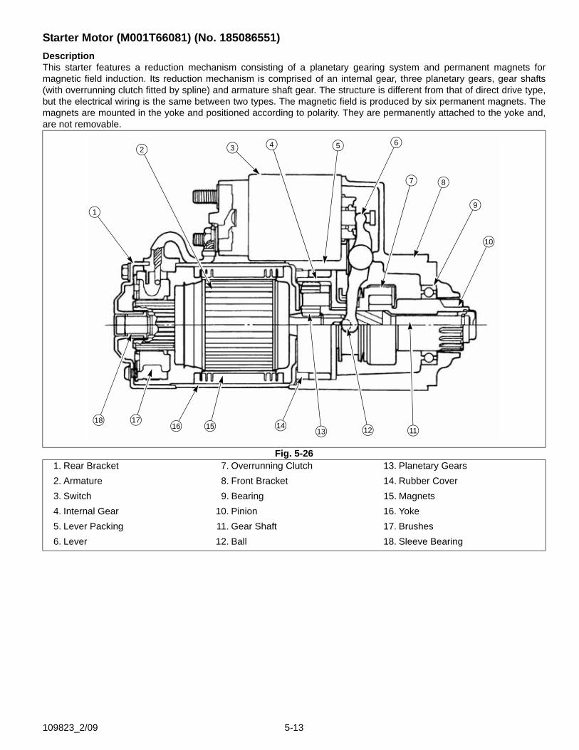
Starter Motor (M001T66081) (No. 185086551)DescriptionThis starter features a reduction mechanism consisting of a planetary gearing system and permanent magnets formagnetic field induction. Its reduction mechanism is comprised of an internal gear, three planetary gears, gear shafts(with overrunning clutch fitted by spline) and armature shaft gear. The structure is different from that of direct drive type,but the electrical wiring is the same between two types. The magnetic field is produced by six permanent magnets. Themagnets are mounted in the yoke and positioned according to polarity. They are permanently attached to the yoke and,are not removable.
Fig. 5-261. Rear Bracket 7. Overrunning Clutch 13. Planetary Gears2. Armature 8. Front Bracket 14. Rubber Cover3. Switch 9. Bearing 15. Magnets4. Internal Gear 10. Pinion 16. Yoke5. Lever Packing 11. Gear Shaft 17. Brushes6. Lever 12. Ball 18. Sleeve Bearing
1
2 3 4 5 6
7 8
9
111213141516
1718
10
109823_2/09 5-13
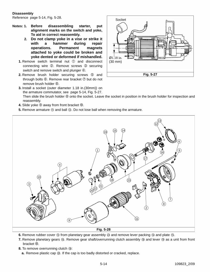
DisassemblyReference page 5-14, Fig. 5-28.
Notes: 1. Before disassembling starter, putalignment marks on the switch and yoke,To aid in correct reassembly.
2. Do not clamp yoke in a vise or strike itwith a hammer during repairoperations. Permanent magnetsattached to yoke could be broken andyoke dented or deformed if mishandled.
1. Remove switch terminal nut and disconnectconnecting wire . Remove screws securingswitch and remove switch and plunger .
2. Remove brush holder securing screws andthrough bolts . Remove rear bracket but do notremove brush holder .
3. Install a socket (outer diameter 1.18 in.(30mm)) onthe armature commutator, see page 5-14, Fig. 5-27.Then slide the brush holder onto the socket. Leave the socket in position in the brush holder for inspection andreassembly.
4. Slide yoke away from front bracket .5. Remove armature and ball . Do not lose ball when removing the armature.
6. Remove rubber cover from planetary gear assembly and remove lever packing and plate .7. Remove planetary gears . Remove gear shaft/overrunning clutch assembly and lever as a unit from front
bracket .8. To remove overrunning clutch :
a. Remove plastic cap . If the cap is too badly distorted or cracked, replace.
Fig. 5-27
Socket
Ø1.18 in.(30 mm)
11 12
Fig. 5-28
1
2
3
4
5
6
78
9
10
11
1213
1415
16
17
18
2122
20
23
19
13 23 14 15
16 18 19
18
20
5-14 109823_2/09

b. Slide a piece of tubing of suitable size over shaftagainst stop ring ) (see page 5-14, Fig. 5-28and page 5-15, Fig. 5-29).
c. Then tap the tubing with a hammer to remove thestop ring and expose snap ring (see page 5-14,Fig. 5-28 and page 5-15, Fig. 5-29). Remove thetubing from the shaft.
d. Remove the snap ring and the stop ring andseparate the overrunning clutch (see page5-14, Fig. 5-28 and page 5-15, Fig. 5-29) from thegear shaft (see page 5-14, Fig. 5-28 and page5-15, Fig. 5-29). If the snap ring is distorted, it willbe necessary to use a new one on reassembly.
Inspection1. Armature
a. Inspect the armature coil for short-circuit with agrowler armature tester. Replace armature ifshorted.
b. Inspect armature coil for ground with a circuittester ( page 5-15, Fig. 5-30). Replace groundedarmature.
c. Inspect commutator for wear. If below the limit,replace armature.
d. Inspect commutator for insulator depth. Correct ifbelow the limit.
e. Check gear teeth for wear or damage, and replacearmature as necessary.
2. Permanent magnetsa. Check permanent magnets for cracks, damage
and looseness, replace yoke assembly asnecessary.
3. Brushesa. Check brushes for wear. Replace brushes if below
the limit.b. Check brush spring pressure to make sure brush
moves smoothly in brush holder.
Fig. 5-29
Stop ring Snapring
21
22
18
17
Fig. 5-30
Fig. 5-31
Hacksaw blade
Commutator Commutator 0.02–0.03Segment
No Good
Chamfered (0.5–0.8mm)
Good
Insulation
109823_2/09 5-15
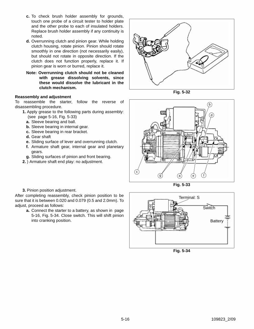
c. To check brush holder assembly for grounds,touch one probe of a circuit tester to holder plateand the other probe to each of insulated holders.Replace brush holder assembly if any continuity isnoted.
d. Overrunning clutch and pinion gear. While holdingclutch housing, rotate pinion. Pinion should rotatesmoothly in one direction (not necessarily easily),but should not rotate in opposite direction. If theclutch does not function properly, replace it. Ifpinion gear is worn or burred, replace it.
Note: Overrunning clutch should not be cleanedwith grease dissolving solvents, sincethese would dissolve the lubricant in theclutch mechanism.
Reassembly and adjustmentTo reassemble the starter, follow the reverse ofdisassembling procedure.
1. Apply grease to the following parts during assembly:(see page 5-16, Fig. 5-33)
a. Sleeve bearing and ball.b. Sleeve bearing in internal gear.c. Sleeve bearing in rear bracket.d. Gear shafte. Sliding surface of lever and overrunning clutch.f. Armature shaft gear, internal gear and planetary
gears.g. Sliding surfaces of pinion and front bearing.
2. ) Armature shaft end play: no adjustment.
3. Pinion position adjustment.After completing reassembly, check pinion position to besure that it is between 0.020 and 0.079 (0.5 and 2.0mm). Toadjust, proceed as follows:
a. Connect the starter to a battery, as shown in page5-16, Fig. 5-34. Close switch. This will shift pinioninto cranking position.
Fig. 5-32
Fig. 5-33
a
b
ceg f
d
Fig. 5-34
Terminal: S
Switch
Battery
5-16 109823_2/09
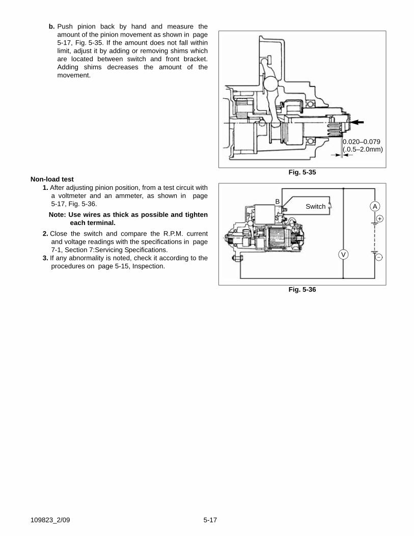
b. Push pinion back by hand and measure theamount of the pinion movement as shown in page5-17, Fig. 5-35. If the amount does not fall withinlimit, adjust it by adding or removing shims whichare located between switch and front bracket.Adding shims decreases the amount of themovement.
Non-load test1. After adjusting pinion position, from a test circuit with
a voltmeter and an ammeter, as shown in page5-17, Fig. 5-36.
Note: Use wires as thick as possible and tighteneach terminal.
2. Close the switch and compare the R.P.M. currentand voltage readings with the specifications in page7-1, Section 7:Servicing Specifications.
3. If any abnormality is noted, check it according to theprocedures on page 5-15, Inspection.
Fig. 5-35
0.020–0.079(.0.5–2.0mm)
Fig. 5-36
SwitchB
A
V –
+
109823_2/09 5-17
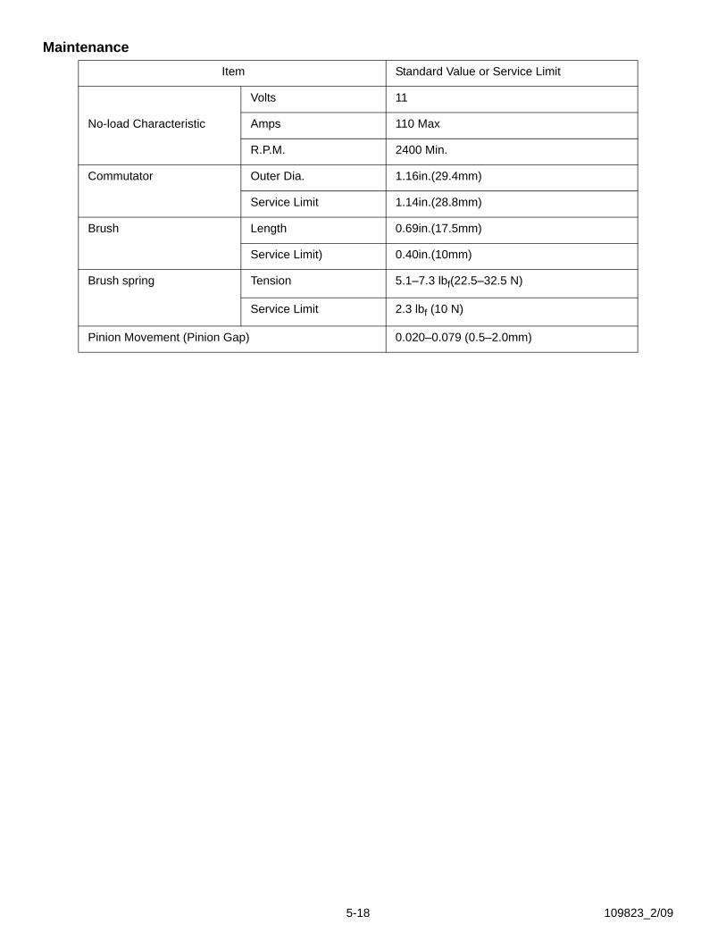
MaintenanceItem Standard Value or Service Limit
Volts 11
No-load Characteristic Amps 110 Max
R.P.M. 2400 Min.
Commutator Outer Dia. 1.16in.(29.4mm)
Service Limit 1.14in.(28.8mm)
Brush Length 0.69in.(17.5mm)
Service Limit) 0.40in.(10mm)
Brush spring Tension 5.1–7.3 lbf(22.5–32.5 N)
Service Limit 2.3 lbf (10 N)
Pinion Movement (Pinion Gap) 0.020–0.079 (0.5–2.0mm)
5-18 109823_2/09
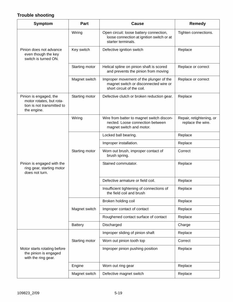
Trouble shooting
Symptom Part Cause Remedy
Wiring Open circuit: loose battery connection, loose connection at ignition switch or at starter terminals.
Tighten connections.
Pinion does not advance even though the key switch is turned ON.
Key switch Defective ignition switch Replace
Starting motor Helical spline on pinion shaft is scored and prevents the pinion from moving
Replace or correct
Magnet switch Improper movement of the plunger of the magnet switch or disconnected wire or short circuit of the coil.
Replace or correct
Pinion is engaged, the motor rotates, but rota-tion is not transmitted to the engine.
Starting motor Defective clutch or broken reduction gear. Replace
Wiring Wire from batter to magnet switch discon-nected. Loose connection between magnet switch and motor.
Repair, retightening, or replace the wire.
Locked ball bearing. Replace
Improper installation. Replace
Starting motor Worn out brush, improper contact of brush spring.
Correct
Pinion is engaged with the ring gear, starting motor does not turn.
Stained commutator. Replace
Defective armature or field coil. Replace
Insufficient tightening of connections of the field coil and brush
Replace
Broken holding coil Replace
Magnet switch Improper contact of contact Replace
Roughened contact surface of contact Replace
Battery Discharged Charge
Improper sliding of pinion shaft Replace
Starting motor Worn out pinion tooth top Correct
Motor starts rotating before the pinion is engaged with the ring gear.
Improper pinion pushing position Replace
Engine Worn out ring gear Replace
Magnet switch Defective magnet switch Replace
109823_2/09 5-19

5-20 109823_2/09
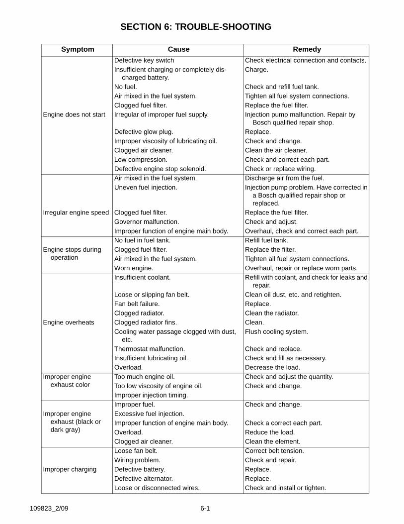
SECTION 6: TROUBLE-SHOOTING
Symptom Cause RemedyDefective key switch Check electrical connection and contacts.Insufficient charging or completely dis-
charged battery.Charge.
No fuel. Check and refill fuel tank.Air mixed in the fuel system. Tighten all fuel system connections.Clogged fuel filter. Replace the fuel filter.
Engine does not start Irregular of improper fuel supply. Injection pump malfunction. Repair by Bosch qualified repair shop.
Defective glow plug. Replace.Improper viscosity of lubricating oil. Check and change.Clogged air cleaner. Clean the air cleaner.Low compression. Check and correct each part.Defective engine stop solenoid. Check or replace wiring.Air mixed in the fuel system. Discharge air from the fuel.Uneven fuel injection. Injection pump problem. Have corrected in
a Bosch qualified repair shop or replaced.
Irregular engine speed Clogged fuel filter. Replace the fuel filter.Governor malfunction. Check and adjust.Improper function of engine main body. Overhaul, check and correct each part.No fuel in fuel tank. Refill fuel tank.
Engine stops during operation
Clogged fuel filter. Replace the filter.Air mixed in the fuel system. Tighten all fuel system connections.Worn engine. Overhaul, repair or replace worn parts.Insufficient coolant. Refill with coolant, and check for leaks and
repair.Loose or slipping fan belt. Clean oil dust, etc. and retighten.Fan belt failure. Replace.Clogged radiator. Clean the radiator.
Engine overheats Clogged radiator fins. Clean.Cooling water passage clogged with dust,
etc.Flush cooling system.
Thermostat malfunction. Check and replace.Insufficient lubricating oil. Check and fill as necessary.Overload. Decrease the load.
Improper engine exhaust color
Too much engine oil. Check and adjust the quantity.Too low viscosity of engine oil. Check and change.Improper injection timing.Improper fuel. Check and change.
Improper engine exhaust (black or dark gray)
Excessive fuel injection.Improper function of engine main body. Check a correct each part.Overload. Reduce the load.Clogged air cleaner. Clean the element.Loose fan belt. Correct belt tension.Wiring problem. Check and repair.
Improper charging Defective battery. Replace.Defective alternator. Replace.Loose or disconnected wires. Check and install or tighten.
109823_2/09 6-1
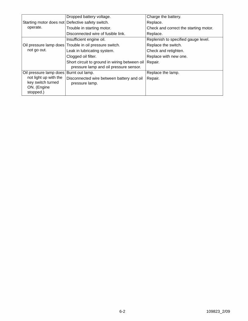
Dropped battery voltage. Charge the battery.Starting motor does not
operate.Defective safety switch. Replace.Trouble in starting motor. Check and correct the starting motor.Disconnected wire of fusible link. Replace.Insufficient engine oil. Replenish to specified gauge level.
Oil pressure lamp does not go out.
Trouble in oil pressure switch. Replace the switch.Leak in lubricating system. Check and retighten.Clogged oil filter. Replace with new one.Short circuit to ground in wiring between oil
pressure lamp and oil pressure sensor.Repair.
Oil pressure lamp does not light up with the key switch turned ON. (Engine stopped.)
Burnt out lamp. Replace the lamp.Disconnected wire between battery and oil
pressure lamp.Repair.
6-2 109823_2/09
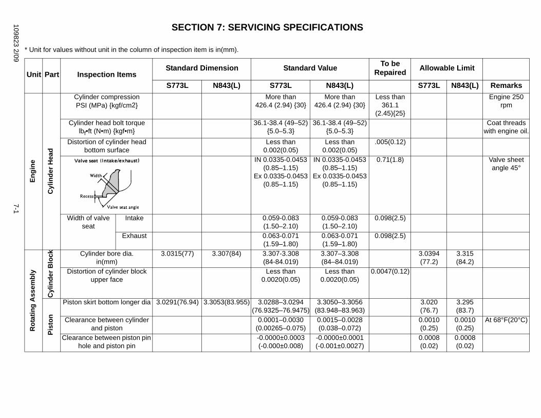
109823 2/097-1
d Allowable Limit
S773L N843(L) Remarksn
}
Engine 250 rpm
Coat threads with engine oil.
2)
) Valve sheet angle 45°
5)
5)
3.0394 (77.2)
3.315 (84.2)
12)
3.020(76.7)
3.295(83.7)
0.0010(0.25)
0.0010(0.25)
At 68°F(20°C)
0.0008(0.02)
0.0008(0.02)
SECTION 7: SERVICING SPECIFICATIONS
* Unit for values without unit in the column of inspection item is in(mm).
Unit Part Inspection ItemsStandard Dimension Standard Value To be
RepaireS773L N843(L) S773L N843(L)
Engi
ne
Cyl
inde
r Hea
d
Cylinder compressionPSI (MPa) {kgf/cm2}
More than426.4 (2.94) {30}
More than426.4 (2.94) {30}
Less tha361.1
(2.45){25Cylinder head bolt torque
lbf•ft (N•m) {kgf•m}36.1-38.4 (49–52)
{5.0–5.3}36.1-38.4 (49–52)
{5.0–5.3}Distortion of cylinder head
bottom surface Less than
0.002(0.05)Less than
0.002(0.05).005(0.1
IN 0.0335-0.0453(0.85–1.15)
Ex 0.0335-0.0453(0.85–1.15)
IN 0.0335-0.0453(0.85–1.15)
Ex 0.0335-0.0453(0.85–1.15)
0.71(1.8
Width of valve seat
Intake 0.059-0.083(1.50–2.10)
0.059-0.083(1.50–2.10)
0.098(2.
Exhaust 0.063-0.071(1.59–1.80)
0.063-0.071(1.59–1.80)
0.098(2.
Rot
atin
g A
ssem
bly
Cyl
inde
r Blo
ck Cylinder bore dia.in(mm)
3.0315(77) 3.307(84) 3.307-3.308(84-84.019)
3.307–3.308(84–84.019)
Distortion of cylinder block upper face
Less than 0.0020(0.05)
Less than 0.0020(0.05)
0.0047(0.
Pist
on
Piston skirt bottom longer dia 3.0291(76.94) 3.3053(83.955) 3.0288–3.0294(76.9325–76.9475)
3.3050–3.3056(83.948–83.963)
Clearance between cylinder and piston
0.0001–0.0030(0.00265–0.075)
0.0015–0.0028(0.038–0.072)
Clearance between piston pin hole and piston pin
-0.0000±0.0003(-0.000±0.008)
-0.0000±0.0001(-0.001±0.0027)
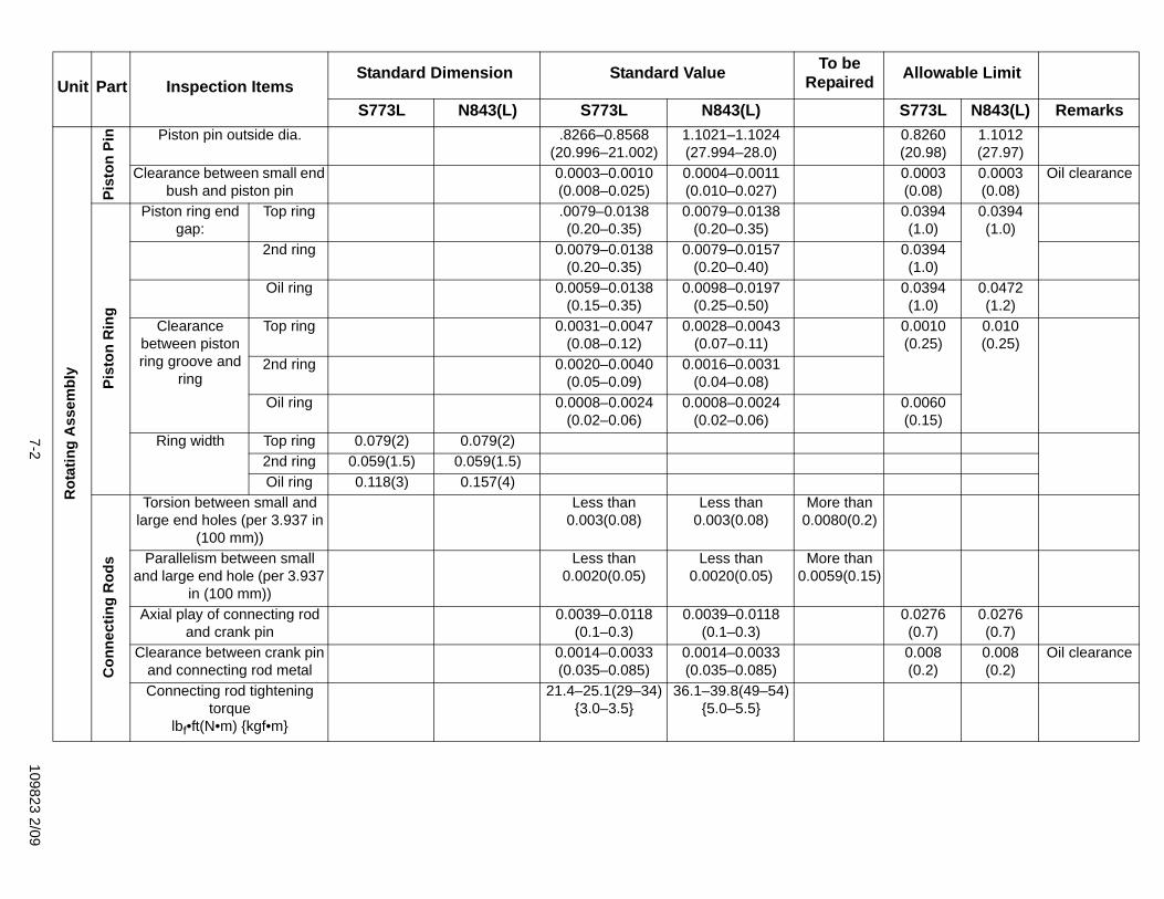
7-2109823 2/09
0.8260(20.98)
1.1012(27.97)
0.0003(0.08)
0.0003(0.08)
Oil clearance
0.0394(1.0)
0.0394(1.0)
0.0394(1.0)
0.0394(1.0)
0.0472(1.2)
0.0010(0.25)
0.010(0.25)
0.0060(0.15)
n .2)
n 15)
0.0276(0.7)
0.0276(0.7)
0.008(0.2)
0.008(0.2)
Oil clearance
d Allowable Limit
S773L N843(L) Remarks
Rot
atin
g A
ssem
bly
Pist
on P
in Piston pin outside dia. .8266–0.8568(20.996–21.002)
1.1021–1.1024(27.994–28.0)
Clearance between small end bush and piston pin
0.0003–0.0010(0.008–0.025)
0.0004–0.0011(0.010–0.027)
Pist
on R
ing
Piston ring end gap:
Top ring .0079–0.0138(0.20–0.35)
0.0079–0.0138(0.20–0.35)
2nd ring 0.0079–0.0138(0.20–0.35)
0.0079–0.0157(0.20–0.40)
Oil ring 0.0059–0.0138(0.15–0.35)
0.0098–0.0197(0.25–0.50)
Clearance between piston ring groove and
ring
Top ring 0.0031–0.0047(0.08–0.12)
0.0028–0.0043(0.07–0.11)
2nd ring 0.0020–0.0040(0.05–0.09)
0.0016–0.0031(0.04–0.08)
Oil ring 0.0008–0.0024(0.02–0.06)
0.0008–0.0024(0.02–0.06)
Ring width Top ring 0.079(2) 0.079(2)2nd ring 0.059(1.5) 0.059(1.5)Oil ring 0.118(3) 0.157(4)
Con
nect
ing
Rod
s
Torsion between small and large end holes (per 3.937 in
(100 mm))
Less than 0.003(0.08)
Less than 0.003(0.08)
More tha0.0080(0
Parallelism between small and large end hole (per 3.937
in (100 mm))
Less than 0.0020(0.05)
Less than 0.0020(0.05)
More tha0.0059(0.
Axial play of connecting rod and crank pin
0.0039–0.0118(0.1–0.3)
0.0039–0.0118(0.1–0.3)
Clearance between crank pin and connecting rod metal
0.0014–0.0033(0.035–0.085)
0.0014–0.0033(0.035–0.085)
Connecting rod tightening torque
lbf•ft(N•m) {kgf•m}
21.4–25.1(29–34){3.0–3.5}
36.1–39.8(49–54){5.0–5.5}
Unit Part Inspection ItemsStandard Dimension Standard Value To be
RepaireS773L N843(L) S773L N843(L)
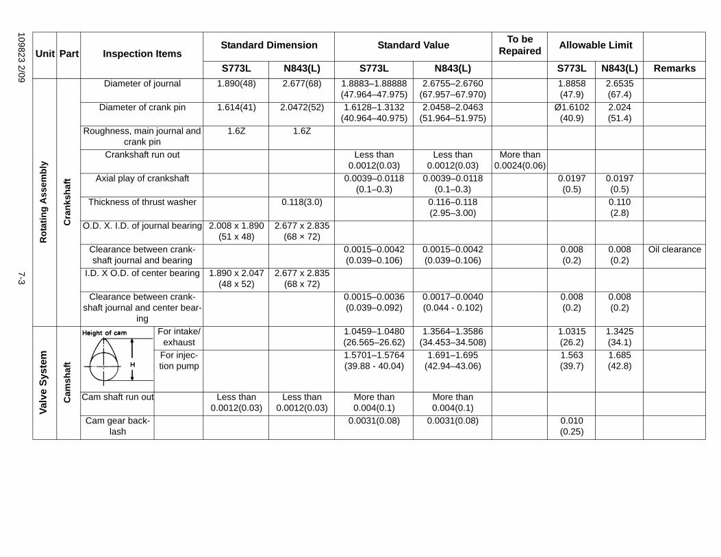
109823 2/097-3
1.8858(47.9)
2.6535(67.4)
Ø1.6102(40.9)
2.024(51.4)
n 06)
0.0197(0.5)
0.0197(0.5)0.110(2.8)
0.008(0.2)
0.008(0.2)
Oil clearance
0.008(0.2)
0.008(0.2)
1.0315(26.2)
1.3425(34.1)
1.563(39.7)
1.685(42.8)
0.010(0.25)
d Allowable Limit
S773L N843(L) Remarks
Rot
atin
g A
ssem
bly
Cra
nksh
aft
Diameter of journal 1.890(48) 2.677(68) 1.8883–1.88888(47.964–47.975)
2.6755–2.6760(67.957–67.970)
Diameter of crank pin 1.614(41) 2.0472(52) 1.6128–1.3132(40.964–40.975)
2.0458–2.0463(51.964–51.975)
Roughness, main journal and crank pin
1.6Z 1.6Z
Crankshaft run out Less than 0.0012(0.03)
Less than 0.0012(0.03)
More tha0.0024(0.
Axial play of crankshaft 0.0039–0.0118(0.1–0.3)
0.0039–0.0118(0.1–0.3)
Thickness of thrust washer 0.118(3.0) 0.116–0.118(2.95–3.00)
O.D. X. I.D. of journal bearing 2.008 x 1.890(51 x 48)
2.677 x 2.835(68 × 72)
Clearance between crank-shaft journal and bearing
0.0015–0.0042(0.039–0.106)
0.0015–0.0042(0.039–0.106)
I.D. X O.D. of center bearing 1.890 x 2.047 (48 x 52)
2.677 x 2.835(68 x 72)
Clearance between crank-shaft journal and center bear-
ing
0.0015–0.0036(0.039–0.092)
0.0017–0.0040(0.044 - 0.102)
Valv
e Sy
stem
Cam
shaf
t
For intake/exhaust
1.0459–1.0480(26.565–26.62)
1.3564–1.3586(34.453–34.508)
For injec-tion pump
1.5701–1.5764(39.88 - 40.04)
1.691–1.695(42.94–43.06)
Cam shaft run out Less than 0.0012(0.03)
Less than 0.0012(0.03)
More than 0.004(0.1)
More than 0.004(0.1)
Cam gear back-lash
0.0031(0.08) 0.0031(0.08)
Unit Part Inspection ItemsStandard Dimension Standard Value To be
RepaireS773L N843(L) S773L N843(L)
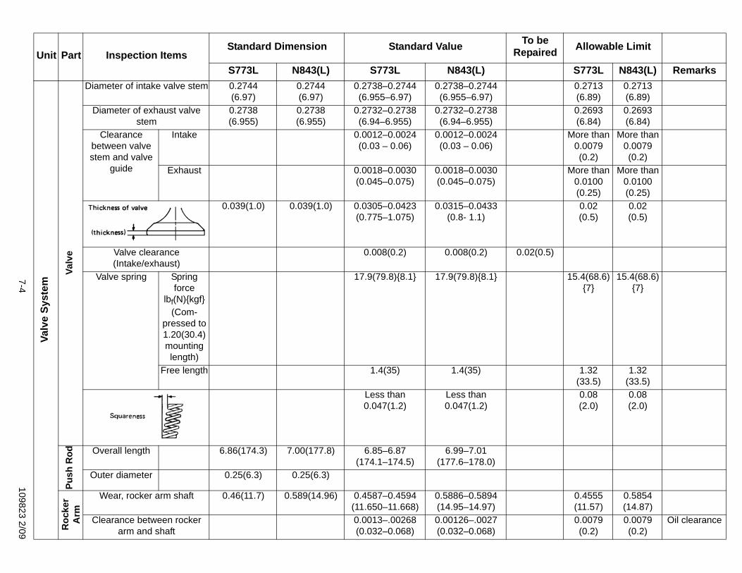
7-4109823 2/09
0.2713(6.89)
0.2713(6.89)
0.2693(6.84)
0.2693(6.84)
More than 0.0079(0.2)
More than 0.0079(0.2)
More than 0.0100(0.25)
More than 0.0100(0.25)
0.02(0.5)
0.02(0.5)
)
15.4(68.6) {7}
15.4(68.6) {7}
1.32(33.5)
1.32(33.5)
0.08(2.0)
0.08(2.0)
0.4555(11.57)
0.5854(14.87)
0.0079(0.2)
0.0079(0.2)
Oil clearance
d Allowable Limit
S773L N843(L) Remarks
Valv
e Sy
stem
Valv
e
Diameter of intake valve stem 0.2744(6.97)
0.2744(6.97)
0.2738–0.2744(6.955–6.97)
0.2738–0.2744(6.955–6.97)
Diameter of exhaust valve stem
0.2738(6.955)
0.2738(6.955)
0.2732–0.2738(6.94–6.955)
0.2732–0.2738(6.94–6.955)
Clearance between valve stem and valve
guide
Intake 0.0012–0.0024(0.03 – 0.06)
0.0012–0.0024(0.03 – 0.06)
Exhaust 0.0018–0.0030(0.045–0.075)
0.0018–0.0030(0.045–0.075)
0.039(1.0) 0.039(1.0) 0.0305–0.0423(0.775–1.075)
0.0315–0.0433(0.8- 1.1)
Valve clearance (Intake/exhaust)
0.008(0.2) 0.008(0.2) 0.02(0.5
Valve spring Spring force
lbf(N){kgf}(Com-
pressed to 1.20(30.4) mounting length)
17.9(79.8){8.1} 17.9(79.8){8.1}
Free length 1.4(35) 1.4(35)
Less than 0.047(1.2)
Less than 0.047(1.2)
Push
Rod Overall length 6.86(174.3) 7.00(177.8) 6.85–6.87
(174.1–174.5)6.99–7.01
(177.6–178.0)Outer diameter 0.25(6.3) 0.25(6.3)
Roc
ker
Arm
Wear, rocker arm shaft 0.46(11.7) 0.589(14.96) 0.4587–0.4594(11.650–11.668)
0.5886–0.5894(14.95–14.97)
Clearance between rocker arm and shaft
0.0013–.00268(0.032–0.068)
0.00126–.0027(0.032–0.068)
Unit Part Inspection ItemsStandard Dimension Standard Value To be
RepaireS773L N843(L) S773L N843(L)
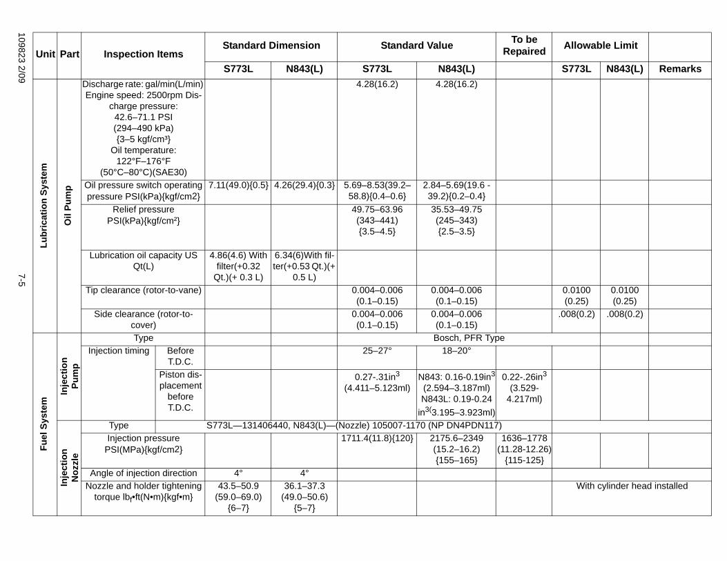
109823 2/097-5
0.0100(0.25)
0.0100(0.25)
.008(0.2) .008(0.2)
n3
l)
7826)}
With cylinder head installed
d Allowable Limit
S773L N843(L) Remarks
Lubr
icat
ion
Syst
em
Oil
Pum
p
Discharge rate: gal/min(L/min) Engine speed: 2500rpm Dis-
charge pressure:42.6–71.1 PSI(294–490 kPa){3–5 kgf/cm³}
Oil temperature:122°F–176°F
(50°C–80°C)(SAE30)
4.28(16.2) 4.28(16.2)
Oil pressure switch operating pressure PSI(kPa){kgf/cm2}
7.11(49.0){0.5} 4.26(29.4){0.3} 5.69–8.53(39.2–58.8){0.4–0.6}
2.84–5.69(19.6 - 39.2){0.2–0.4}
Relief pressure PSI(kPa){kgf/cm²}
49.75–63.96(343–441){3.5–4.5}
35.53–49.75(245–343){2.5–3.5}
Lubrication oil capacity US Qt(L)
4.86(4.6) With filter(+0.32
Qt.)(+ 0.3 L)
6.34(6)With fil-ter(+0.53 Qt.)(+
0.5 L)Tip clearance (rotor-to-vane) 0.004–0.006
(0.1–0.15)0.004–0.006(0.1–0.15)
Side clearance (rotor-to-cover)
0.004–0.006(0.1–0.15)
0.004–0.006(0.1–0.15)
Fuel
Sys
tem
Inje
ctio
nPu
mp
Type Bosch, PFR TypeInjection timing Before
T.D.C.25–27° 18–20°
Piston dis-placement
before T.D.C.
0.27-.31in3
(4.411–5.123ml)N843: 0.16-0.19in3
(2.594–3.187ml)N843L: 0.19-0.24
in3(3.195–3.923ml)
0.22-.26i(3.529-
4.217m
Inje
ctio
nN
ozzl
e
Type S773L—131406440, N843(L)—(Nozzle) 105007-1170 (NP DN4PDN117)Injection pressure
PSI(MPa){kgf/cm2}1711.4(11.8){120} 2175.6–2349
(15.2–16.2){155–165}
1636–17(11.28-12.
{115-125Angle of injection direction 4° 4°
Nozzle and holder tightening torque lbf•ft(N•m){kgf•m}
43.5–50.9(59.0–69.0)
{6–7}
36.1–37.3(49.0–50.6)
{5–7}
Unit Part Inspection ItemsStandard Dimension Standard Value To be
RepaireS773L N843(L) S773L N843(L)

7-6109823 2/09
0.0079(0.2)
0.0079(0.2)
n 8)
0.35(9) 0.35(9)Less than 1.98(8.8)
{0.9}
Less than 1.98(8.8)
{0.912V–40A
0.87(22.1)
0.197(5.0)
d Allowable Limit
S773L N843(L) Remarks
Coo
ling
Syst
em
Coo
ling
Cooling method Forced circulation water coolingCoolant water volume US
Qt(L)2.0(1.9) 5.3(5)
Type 145206061Thermostat open
temperature F°(°C)167(75) 180(82)
Thermostat full-openTemperature F°(°C)
189(87) 203(95)
V belt (fan) looseness (load at center 11lb(5kg))
0.19–0.39(5–10) 0.19–0.39(5–10)
Elec
tric
al S
yste
m
Star
ter M
otor
Type 185086670 M001T66081No. of teeth of pinion gear 9 11Shifting method of pinion Magnetic shifting
Wear of commutator diameter 1.16(29.4) 1.16(29.4) 1.13(28.8)
Stepped wear of commutator 0.002(0.05) 0.002(0.05)
Bending allowance of arma-ture shaft
0.002(0.05) 0.002(0.05) More tha0.003(0.0
Length of brush 0.69(17.5) 0.69(17.5)Spring force of brush
lbf(N){kgf}5.06–7.31
(22.5–32.5){2.3–3.3}
5.06–7.31(22.5–32.5){2.3–3.3}
Alte
rnat
or
Type 185046440 A007T03877Outside diameter of slip ring 0.89(22.7) 0.89(22.7)
Length of brush 0.73(18.5) 0.73(18.5)Pulley tightening torque
lbf•ft(N•m){kgf•m}42.8–58.3(58–79)
{5.95–8.05}42.8–58.3(58–79)
{5.95–8.05}
Unit Part Inspection ItemsStandard Dimension Standard Value To be
RepaireS773L N843(L) S773L N843(L)
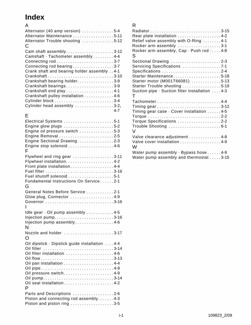
i-1 109823_2/09
IndexAAlternator (40 amp version) . . . . . . . . . . . . . . 5-4Alternator Maintenance . . . . . . . . . . . . . . . . . . 5-11Alternator Trouble shooting . . . . . . . . . . . . . . 5-12CCam shaft assembly. . . . . . . . . . . . . . . . . . . . . 3-12Camshaft · Tachometer assembly . . . . . . . . . 4-4Connecting rod . . . . . . . . . . . . . . . . . . . . . . . . . 3-7Connecting rod bearing . . . . . . . . . . . . . . . . . . 3-7Crank shaft and bearing holder assembly . . 4-1Crankshaft . . . . . . . . . . . . . . . . . . . . . . . . . . . . . 3-10Crankshaft bearing holder. . . . . . . . . . . . . . . . 3-9Crankshaft bearings . . . . . . . . . . . . . . . . . . . . . 3-9Crankshaft end play . . . . . . . . . . . . . . . . . . . . . 4-1Crankshaft pulley installation . . . . . . . . . . . . . 4-6Cylinder block . . . . . . . . . . . . . . . . . . . . . . . . . . 3-4Cylinder head assembly . . . . . . . . . . . . . . . . . 3-2,
4-7EElectrical Systems . . . . . . . . . . . . . . . . . . . . . . 5-1Engine glow plugs . . . . . . . . . . . . . . . . . . . . . . 5-2Engine oil pressure switch . . . . . . . . . . . . . . . 5-3Engine Removal . . . . . . . . . . . . . . . . . . . . . . . . 2-5Engine Sectional Drawing . . . . . . . . . . . . . . . . 2-3Engine stop solenoid . . . . . . . . . . . . . . . . . . . . 4-6FFlywheel and ring gear . . . . . . . . . . . . . . . . . . 3-11Flywheel installation. . . . . . . . . . . . . . . . . . . . . 4-2Front plate installation . . . . . . . . . . . . . . . . . . . 4-4Fuel filter . . . . . . . . . . . . . . . . . . . . . . . . . . . . . . 3-16Fuel shutoff solenoid . . . . . . . . . . . . . . . . . . . . 5-1Fundamental Instructions On Service . . . . . . 2-1GGeneral Notes Before Service . . . . . . . . . . . . 2-1Glow plug, Connector . . . . . . . . . . . . . . . . . . . 4-9Governor . . . . . . . . . . . . . . . . . . . . . . . . . . . . . . 3-16IIdle gear · Oil pump assembly . . . . . . . . . . . . 4-5Injection pump. . . . . . . . . . . . . . . . . . . . . . . . . . 3-16Injection pump assembly . . . . . . . . . . . . . . . . . 4-6NNozzle and holder . . . . . . . . . . . . . . . . . . . . . . 3-17OOil dipstick · Dipstick guide installation . . . . 4-4Oil filter . . . . . . . . . . . . . . . . . . . . . . . . . . . . . . . 3-14Oil filter installation . . . . . . . . . . . . . . . . . . . . . 4-6Oil flow . . . . . . . . . . . . . . . . . . . . . . . . . . . . . . . . 3-13Oil pan installation . . . . . . . . . . . . . . . . . . . . . . 4-4Oil pipe . . . . . . . . . . . . . . . . . . . . . . . . . . . . . . . . 4-9Oil pressure switch. . . . . . . . . . . . . . . . . . . . . . 4-9Oil pump. . . . . . . . . . . . . . . . . . . . . . . . . . . . . . . 3-14Oil seal installation. . . . . . . . . . . . . . . . . . . . . . 4-2PParts and Descriptions . . . . . . . . . . . . . . . . . . 2-6Piston and connecting rod assembly. . . . . . . 4-3Piston and piston ring . . . . . . . . . . . . . . . . . . . 3-5
RRadiator . . . . . . . . . . . . . . . . . . . . . . . . . . . . . . . 3-15Rear plate installation . . . . . . . . . . . . . . . . . . . 4-2Relief valve assembly with O-Ring . . . . . . . . 4-1Rocker arm assembly . . . . . . . . . . . . . . . . . . . 3-1Rocker arm assembly, Cap · Push rod · . . . . 4-8SSectional Drawing . . . . . . . . . . . . . . . . . . . . . . 2-3Servicing Specifications . . . . . . . . . . . . . . . . . 7-1Specifications . . . . . . . . . . . . . . . . . . . . . . . . . . 2-4Starter Maintenance. . . . . . . . . . . . . . . . . . . . . 5-18Starter motor (M001T66081) . . . . . . . . . . . . . 5-13Starter Trouble shooting . . . . . . . . . . . . . . . . . 5-19Suction pipe · Suction filter installation . . . . 4-3TTachometer . . . . . . . . . . . . . . . . . . . . . . . . . . . . 4-4Timing gear . . . . . . . . . . . . . . . . . . . . . . . . . . . . 3-12Timing gear case · Cover installation . . . . . . 4-5Torque . . . . . . . . . . . . . . . . . . . . . . . . . . . . . . . . 2-2Torque Specifications . . . . . . . . . . . . . . . . . . . 2-2Trouble Shooting . . . . . . . . . . . . . . . . . . . . . . . 6-1VValve clearance adjustment . . . . . . . . . . . . . . 4-8Valve cover installation . . . . . . . . . . . . . . . . . . 4-9WWater pump assembly · Bypass hose . . . . . . 4-9Water pump assembly and thermostat . . . . . 3-15


