Scotsman Ice Srl Via Lainate, 31 - 20010 Pogliano M.se - Milano - Italy Tel. +39-02-93960.1 (Aut. Sel.)- Telefax +39-02-93550500 Direct Line to Service & Parts: Phone +39-02-93960350 - Fax +39-02-93540449 Website: www.scotsman-ice.it E-Mail: [email protected]ISO 9001 - Cert. n. 0080 SERVICE MANUAL AC 106 AC 126 AC 126 (R404a) from s.n. 06986 AC 176 AC 176 (R404a) from s.n. 11170 AC 206 AC 226 Electronic cubers with storage New PC Board version REV. 10/2016
Transcript
Page 1Page 1
Scotsman Ice SrlVia Lainate, 31 - 20010 Pogliano M.se - Milano - ItalyTel. +39-02-93960.1 (Aut. Sel.)- Telefax +39-02-93550500Direct Line to Service & Parts:Phone +39-02-93960350 - Fax +39-02-93540449Website: www.scotsman-ice.itE-Mail: [email protected]
ISO 9001 - Cert. n. 0080
SERVICE MANUAL
AC 106AC 126
AC 126 (R404a) from s.n. 06986
AC 176AC 176 (R404a) from s.n. 11170
AC 206AC 226
Electronic cubers with storage
New PC Board version
REV. 10/2016
LED STATUS REASON WHY - SIGNIFICATION - SIGNIFICATO
ON STEADYFIXE
FISSO
FREEZING CYCLEEN RÉFRIGÉRATIONIN CONGELAMENTO
BLINKINGCLIGNOTANT
LAMPEGGIANTE
60 MINUTES DELAY AT START UP JUMPER J3 OUT60 MINUTES DE RETARD AU DEMARRAGE - CAVALIER J3 OUVERTE60 MINUTI RITARDO PARTENZA - CONTATTI J3 APERTI
ON STEADYFIXE
FISSO
TOO HI DISCHARGE PRESSURE/TEMP.COUPURE HPFERMATA ALTA TEMP. CONDENSAZIONE
BLINKINGCLIGNOTANT
LAMPEGGIANTE
TOO HI EVAP. TEMP. (> 0°C) AFTER 15’ FROM START UPCOUPURE BP ( > 0°C LU PAR LA SONDE EVAP. NON ATTEINTE APRES 15’ FONCT.)TEMP. EVAP. > 0°C DOPO 15’ DA INIZIO CONGELAMENTO
ON STEADYFIXE
FISSO
UNIT OFF AT BIN FULLCABINE PLEINECONTENITORE PIENO
BLINKING SLOWCLIGNOTANT LENTLAMPEGG. LENTO
I/R BEAM CUTTEDFAISCEAU INFRA ROUGE CELLULE NIVEAU GLACE INTERROMPURAGGIO INFRAROSSO INTERROTTO
BLINKING FASTCLIGNOTANT RAPIDELAMPEGG. VELOCE
I/R ON AFTER TRIP OFF AT BIN FULLFAISCEAU INFRA ROUGE CELLULE NIVEAU GLACE ETABLIRAGGIO INFRAROSSO RIPRISTINATO DOPO FERMATA A CONT. PIENO
ON STEADYFIXE
FISSO
I/R CALIBRATION DONECALIBRATION FAISCEAU INFRA ROUGE CELL. NIVEAU GLACE REALISÉCALIBRAZIONE RAGGIO INFRAROSSO EFFETTUATA
BLINKINGCLIGNOTANT
LAMPEGGIANTE
UNIT IN CLEANING MODE OR TRIPPING OFF AFTER TEST - JUMPER TEST INMACHINE EN MODE DETARTRAGE OU ARRÊTE APRES LE TEST - CAVALIER TEST FERMÉMACCHINA NELLA FASE LAVAGGIO O FERMA DOPO IL TEST - PONTICELLO TEST CHIUSO
ON STEADYFIXE
FISSO
CONDENSER SENSOR OUT OF ORDERSONDE CONDENSEUR HSSONDA CONDENSATORE MALFUNZIONANTE
BLINKINGCLIGNOTANT
LAMPEGGIANTE
EVAPORATOR SENSOR OUT OF ORDERSONDE EVAPORATEURS HSSONDA EVAPORATORE MALFUNZIONANTE
I/R SENSOR OUT OF ORDERSONDE INFRA ROUGE CELLULE NIVEAU GLACE HSSONDA ALL’INFRAROSSO LIVELLO GHIACCIO MALFUNZIONANTE
PUSH
PUSH > 5” DURING WATER FILLING TO MOVE THE UNIT INTO FREEZINGPUSH > 5” DURING FREEZING TO MOVE THE UNIT INTO DEFROSTPUSH > 5” DURING DEFROST TO MOVE THE UNIT INTO FREEZING
PUSH 2” ÷ 5” DURING WATER FILLING TO MOVE THE UNIT INTO CLEANINGPUSH DURING THE 60 MIN START UP DELAY TIME TO BY-PASS IT
OFF OFFWATER PUMP OFF DURING DEFROSTPOMPE A L’ARRÊT PEND. DEGIVRAGE
POMPA ACQUA DURANTE SBRINAMENTO
7 8
ON ON 0
OFF ON 30 sec.
ON OFF 60 sec.
ADDITIONAL DEFROST TIMETEMPS AJOUTÉS
TEMPI AGG. SCONGELAMENTO
AIR/EAUARIA/ACQUA
651396 00
LED STATUS REASON WHY - SIGNIFICATION - SIGNIFICATO
ON STEADYFIXE
FISSO
FREEZING CYCLEEN RÉFRIGÉRATIONIN CONGELAMENTO
BLINKINGCLIGNOTANT
LAMPEGGIANTE
60 MINUTES DELAY AT START UP JUMPER J3 OUT60 MINUTES DE RETARD AU DEMARRAGE - CAVALIER J3 OUVERTE60 MINUTI RITARDO PARTENZA - CONTATTI J3 APERTI
ON STEADYFIXE
FISSO
TOO HI DISCHARGE PRESSURE/TEMP.COUPURE HPFERMATA ALTA TEMP. CONDENSAZIONE
BLINKINGCLIGNOTANT
LAMPEGGIANTE
TOO HI EVAP. TEMP. (> 0°C) AFTER 15’ FROM START UPCOUPURE BP ( > 0°C LU PAR LA SONDE EVAP. NON ATTEINTE APRES 15’ FONCT.)TEMP. EVAP. > 0°C DOPO 15’ DA INIZIO CONGELAMENTO
ON STEADYFIXE
FISSO
UNIT OFF AT BIN FULLCABINE PLEINECONTENITORE PIENO
BLINKING SLOWCLIGNOTANT LENTLAMPEGG. LENTO
I/R BEAM CUTTEDFAISCEAU INFRA ROUGE CELLULE NIVEAU GLACE INTERROMPURAGGIO INFRAROSSO INTERROTTO
BLINKING FASTCLIGNOTANT RAPIDELAMPEGG. VELOCE
I/R ON AFTER TRIP OFF AT BIN FULLFAISCEAU INFRA ROUGE CELLULE NIVEAU GLACE ETABLIRAGGIO INFRAROSSO RIPRISTINATO DOPO FERMATA A CONT. PIENO
ON STEADYFIXE
FISSO
I/R CALIBRATION DONECALIBRATION FAISCEAU INFRA ROUGE CELL. NIVEAU GLACE REALISÉCALIBRAZIONE RAGGIO INFRAROSSO EFFETTUATA
BLINKINGCLIGNOTANT
LAMPEGGIANTE
UNIT IN CLEANING MODE OR TRIPPING OFF AFTER TEST - JUMPER TEST INMACHINE EN MODE DETARTRAGE OU ARRÊTE APRES LE TEST - CAVALIER TEST FERMÉMACCHINA NELLA FASE LAVAGGIO O FERMA DOPO IL TEST - PONTICELLO TEST CHIUSO
ON STEADYFIXE
FISSO
CONDENSER SENSOR OUT OF ORDERSONDE CONDENSEUR HSSONDA CONDENSATORE MALFUNZIONANTE
BLINKINGCLIGNOTANT
LAMPEGGIANTE
EVAPORATOR SENSOR OUT OF ORDERSONDE EVAPORATEURS HSSONDA EVAPORATORE MALFUNZIONANTE
I/R SENSOR OUT OF ORDERSONDE INFRA ROUGE CELLULE NIVEAU GLACE HSSONDA ALL’INFRAROSSO LIVELLO GHIACCIO MALFUNZIONANTE
PUSH
PUSH > 5” DURING WATER FILLING TO MOVE THE UNIT INTO FREEZINGPUSH > 5” DURING FREEZING TO MOVE THE UNIT INTO DEFROSTPUSH > 5” DURING DEFROST TO MOVE THE UNIT INTO FREEZING
PUSH 2” ÷ 5” DURING WATER FILLING TO MOVE THE UNIT INTO CLEANINGPUSH DURING THE 60 MIN START UP DELAY TIME TO BY-PASS IT
OFF OFFWATER PUMP OFF DURING DEFROSTPOMPE A L’ARRÊT PEND. DEGIVRAGE
POMPA ACQUA DURANTE SBRINAMENTO
7 8
ON ON 0
OFF ON 30 sec.
ON OFF 60 sec.
ADDITIONAL DEFROST TIMETEMPS AJOUTÉS
TEMPI AGG. SCONGELAMENTO
1 2 3 4
A/ECS 206 A
A/ECS 206 W
A/ECS 226 A
A/ECS 226 W
A/ECM 206 A
A/ECM 206 W
A/ECM 226 A
A/ECM 226 W
A/ECL 206 A
A/ECL 206 W
A/ECL 226 A
A/ECL 226 W
5 6 7 8 9 10ON
ON
ON
ON
OFF
OFF
ON
ON
OFF
OFF
OFF
OFF
OFF
OFF
OFF
OFF
OFF
OFF
ON
ON
OFF
OFF
OFF
OFF
ON
ON
ON
ON
ON
ON
OFF
OFF
OFF
OFF
OFF
OFF
ON
ON
ON
ON
ON
ON
ON
ON
ON
ON
ON
ON
OFF
OFF
OFF
OFF
OFF
OFF
OFF
OFF
OFF
OFF
OFF
OFF
ON
ON
ON
ON
ON
ON
ON
ON
OFF
OFF
ON
ON
ON
ON
ON
ON
ON
ON
ON
ON
ON
ON
ON
ON
ON
ON
ON
ON
ON
ON
ON
ON
ON
ON
ON
ON
OFF
OFF
ON
ON
ON
ON
ON
ON
ON
ON
ON
ON
ON
OFF
ON
OFF
OFF
OFF
ON
OFF
ON
OFF
ON
OFF
DIP SWITCH FACTORY SETTING COMBINATIONS (PER MODEL AND VERSION)COMBINAISON DES COMMUTATEURS NUMERIQUES DU DIP SWITCH POUR MODELES ET VERSIONS
REGOLAZIONE TASTI DIP SWITCH PER MODELLO E VERSIONE
DIP SWITCH
FREEZING CYCLECYCLE DE CONGÉLATIONCICLO CONGELAMENTO
DEFROST CYCLECYCLE DE DÉMOULAGECICLO SBRINAMENTO
15/30" AIR/EAUARIA/ACQUA
651396 01
Page 2Page 2
INDICE2358
1113
15151515161617
1819
Table of contents pageSpecifications AC 106Specifications AC 126Specifications AC 176Specifications AC 206Specifications AC 226
GENERAL INFORMATION AND INSTALLATION
IntroductionUnpacking and InspectionLocation and levellingElectrical connectionsWater supply and drain connectionsFinal check listInstallation practice
Adjustment of the cube sizeWiring diagram AC 106 - AC 126 - AC 176 - AC 206 - AC 226Wiring diagram ACS 126 - ACS 176Service diagnosis
MAINTENANCE AND CLEANING INSTRUCTIONSGeneralIcemakerClean - Replace of air condenser filterCleaning instructions of water system
343536
374
24272829
40404143
Page 3Page 3
MIN.10°C 5°C1 bar
-10%
Important operating requirements:
Air temperatureWater temperatureWater pressureElectr. voltage variationsfrom voltage ratingspecifiedon nameplate
SPECIFICATIONS
ELECTRONIC CUBER MODEL AC 106
MAX.40°C35°C5 bar
+10%
ice making capacity
NOTE. With the unit in "built-in" conditions, the ice production is gradually reduced in respect to thelevels shown in the graf, up to a maximum of 10% at room temperatures higher than 32°C.The daily ice-making capacity is directly related to the condenser air inlet temperature, watertemperature conditions of the condenser air filter and age of the machine.To keep your SCOTSMAN CUBER at peak performance levels, periodic maintenance checks mustbe carried out as indicated on Maintenance and Cleaning section of this manual.
AIR COOLED MODELS
WATER TEMPERATURE
AM
BIE
NT
TE
MP
ER
AT
UR
E
ICE
PR
OD
UC
ED
PE
R 2
4 H
RS
.
WATER COOLED MODELS
AM
BIE
NT
TE
MP
ER
AT
UR
E
ICE
PR
OD
UC
ED
PE
R 2
4 H
RS
.
WATER TEMPERATURE
50
48
46
44
42
40
38
36
34
32
Kg.
10
21
32
38
°Co
32 27 21 15 10 °Co
51
49
47
45
43
41
39
37
35
Kg.
10
21
32
38
32 27 21 15 10 °Co
Page 4Page 4
AC 106 AS 6 AirAC 106 WS 6 Water
Stainless steel 3/8 23 Kg.
Start . Electric power cons.Amps Kwh per 24 Hr
Model Cond. unit Finish Comp. HP
SPECIFICATIONS
Basic electr. Amps Watts Nr. of wires Amps fuse
230/50/1 3.3 18 550 3 x 1.5 mm2 10
0136 **550*
AC 106 - CUBERmachine specifications
Cubes per harvest: 32 medium* A 15°C water temperature
Air temperatureWater temperatureWater pressureElectr. voltage variationsfrom voltage ratingspecifiedon nameplate
SPECIFICATIONS
ELECTRONIC CUBER MODEL AC 126
MAX.40°C35°C5 bar
+10%
ice making capacity
NOTE. With the unit in "built-in" conditions, the ice production is gradually reduced in respect to thelevels shown in the graf, up to a maximum of 10% at room temperatures higher than 32°C.The daily ice-making capacity is directly related to the condenser air inlet temperature, watertemperature conditions of the condenser air filter and age of the machine.To keep your SCOTSMAN CUBER at peak performance levels, periodic maintenance checks mustbe carried out as indicated on Maintenance and Cleaning section of this manual.
AIR COOLED MODELS
WATER TEMPERATURE
AM
BIE
NT
TE
MP
ER
AT
UR
E
ICE
PR
OD
UC
ED
PE
R 2
4 H
RS
.
WATER COOLED MODELS
AM
BIE
NT
TE
MP
ER
AT
UR
E
ICE
PR
OD
UC
ED
PE
R 2
4 H
RS
.
WATER TEMPERATURE
75
70
65
60
55
50
45
Kg.
10
21
32
38
°Co
32 27 21 15 10 °Co
75
70
65
60
55
50
45
Kg.
1021
3238
°Co
32 27 21 15 10
Page 6Page 6
AC 126 AS 6 AirAC 126 WS 6 Water
Stainless steel 1/2 39 Kg.
Start . Electric power cons.Amps Kwh per 24 Hr
Model Cond. unit Finish Comp. HP
SPECIFICATIONS
Basic electr. Amps Watts Nr. of wires Amps fuse
230/50/1 4 19 600 3 x 1.5 mm2 10
190*750*
AC 126 - CUBER (R134a version)machine specifications
Cubes per harvest: 48 medium* A 15°C water temperature
Air temperatureWater temperatureWater pressureElectr. voltage variationsfrom voltage ratingspecifiedon nameplate
SPECIFICATIONS
ELECTRONIC CUBER MODEL AC 176
MAX.40°C35°C5 bar
+10%
ice making capacity
NOTE. With the unit in "built-in" conditions, the ice production is gradually reduced in respect to thelevels shown in the graf, up to a maximum of 10% at room temperatures higher than 32°C.The daily ice-making capacity is directly related to the condenser air inlet temperature, watertemperature conditions of the condenser air filter and age of the machine.To keep your SCOTSMAN CUBER at peak performance levels, periodic maintenance checks mustbe carried out as indicated on Maintenance and Cleaning section of this manual.
AIR COOLED MODELS
WATER TEMPERATURE
AM
BIE
NT
TE
MP
ER
AT
UR
E
ICE
PR
OD
UC
ED
PE
R 2
4 H
RS
.
WATER COOLED MODELS
84
82
80
78
76
74
72
70
68
66
64
62
60
58
56
Kg.
10
21
32
38
°Co
32 27 21 15 10 °Co
WATER TEMPERATURE
AM
BIE
NT
TE
MP
ER
AT
UR
E
ICE
PR
OD
UC
ED
PE
R 2
4 H
RS
.
86
84
82
80
78
76
74
72
70
68
66
64
62
60
58
Kg.
10
21
32
38
°Co
32 27 21 15 10 °Co
Page 9Page 9
AC 176 AS 6 AirAC 176 WS 6 Water
Stainless steel 3/4 48 Kg.
Start . Electric power cons.Amps Kwh per 24 Hr
Model Cond. unit Finish Comp. HP
SPECIFICATIONS
Basic electr. Amps Watts Nr. of wires Amps fuse
230/50/1 5.6 26 760 3 x 1.5 mm2 10
150*1050*
AC 176 - CUBER (R134a version)machine specifications
Cubes per harvest: 48 medium* A 15°C water temperature
Air temperatureWater temperatureWater pressureElectr. voltage variationsfrom voltage ratingspecifiedon nameplate
SPECIFICATIONS
ELECTRONIC CUBER MODEL AC 206
MAX.40°C35°C5 bar
+10%
ice making capacity
NOTE. The daily ice-making capacity is directly related to the condenser air inlet temperature, watertemperature conditions of the condenser air filter and age of the machine.Production charts shown indicate the production of ACM models; ice production of ACL and ACSmodels is 10% lower.To keep your SCOTSMAN CUBER at peak performance levels, periodic maintenance checks mustbe carried out as indicated on Maintenance and Cleaning section of this manual.
AIR COOLED MODELS
WATER TEMPERATURE
AM
BIE
NT
TE
MP
ER
AT
UR
E
ICE
PR
OD
UC
ED
PE
R 2
4 H
RS
.
WATER COOLED MODELS
130128126124122120118116114112110108106104102100
989694929088868482807876747270
Kg.10
21
32
38
°C
32 27 21 15 10 °C
WATER TEMPERATURE
AM
BIE
NT
TE
MP
ER
AT
UR
E
ICE
PR
OD
UC
ED
PE
R 2
4 H
RS
.
138
136
134
132
130
128
126
124
122
120
118
116
114
112
110
108
106
104
102
100
98
96
Kg.
1021
32
38
°C
32 27 21 15 10 °C
Page 12Page 12
Stainless steel 1/2 50 Kg.
Start . Electric power cons.Amps Kwh per 24 Hr
Model Cond. unit Finish Comp. HP
SPECIFICATIONS
Basic electr. Amps Watts Nr. of wires Amps fuse
230/50/1 4.7 19 950 3 x 1.5 mm2 16
280*1400*
AC 206 - CUBERmachine specifications
Cubes per harvest: 72 large / 102 medium / 198 small* A 15°C water temperature
Air temperatureWater temperatureWater pressureElectr. voltage variationsfrom voltage ratingspecifiedon nameplate
SPECIFICATIONS
ELECTRONIC CUBER MODEL AC 226
MAX.40°C35°C5 bar
+10%
ice making capacityAIR COOLED MODELS
WATER TEMPERATURE
AM
BIE
NT
TE
MP
ER
AT
UR
E
ICE
PR
OD
UC
ED
PE
R 2
4 H
RS
.
WATER COOLED MODELS
148
144
140
136
132
128
124
120
116
112
108
104
100
96
92
88
84
Kg.
1021
32
38
°Co
32 27 21 15 10 °Co
WATER TEMPERATURE
AM
BIE
NT
TE
MP
ER
AT
UR
E
ICE
PR
OD
UC
ED
PE
R 2
4 H
RS
.
152
148
144
140
136
132
128
124
120
116
112
108
Kg.
10
21
32
38
°Co
32 27 21 15 10 °Co
NOTE. The daily ice-making capacity is directly related to the condenser air inlet temperature, watertemperature conditions of the condenser air filter and age of the machine.Production charts shown indicate the production of ACM models; ice production of ACL and ACSmodels is 10% lower.To keep your SCOTSMAN CUBER at peak performance levels, periodic maintenance checks mustbe carried out as indicated on Maintenance and Cleaning section of this manual.
Page 14Page 14
AC 226 AS 6 AirAC 226 WS 6 Water
Stainless steel 1 70 Kg.
Start . Electric power cons.Amps Kwh per 24 Hr
Model Cond. unit Finish Comp. HP
SPECIFICATIONS
Basic electr. Amps Watts Nr. of wires Amps fuse
230/50/1 5.2 29 1180 3 x 1.5 mm2 16
330*1800*
AC 226 - CUBERmachine specifications
Cubes per harvest: 72 large / 102 medium / 198 small* A 15°C water temperature
Forward the completed self-addressedregistration card to Frimont factory.
11. If necessary, replace the four standard legswith the taller ones supplied in the machine andadjust them to level the unit.
C. LOCATION AND LEVELLING
WARNING. This Ice Cuber is designed forindoor installation only. Extended periodsof operation at temperatures exceedingthe following limitations will constitutemisuse under the terms of the SCOTSMANManufacturer’s Limited Warranty resultingin LOSS of warranty coverage.
1. Position the unit in the selected permanentlocation.Criteria for selection of location include:
a) Minimum room temperature 10°C (50°F)and maximum room temperature 40°C (100°F).
b) Water inlet temperatures: minimum 5°C(40°F) and maximum 35°C (90°F).
c) Well ventilated location for air cooledmodels.
d) Service access: adequate space mustbe left for all service connections through the rearof the ice maker. A minimum clearance of 15 cm(6") must be left at the sides of the unit for routingcooling air drawn into and exhausted out of thecompartment to maintain proper condensingoperation of air cooled models.
2. Level the unit in both the left to right andfront to rear directions.
D. ELECTRICAL CONNECTIONS
See data plate for current requirements todetermine wire size to be used for electricalconnections. All SCOTSMAN icemakers requirea solid earth wire.All SCOTSMAN ice machines are supplied fromthe factory completely pre-wired and require onlyelectrical power connections to the wire cordprovided at rear of the unit.Make sure that the ice machine is connected toits own circuit and individually fused (see dataplate for fuse size).The maximum allowable voltage variation shouldnot exceed -10% and + 10% of the data platerating. Low voltage can cause faulty functioningand may be responsible for serious damage tothe overload switch and motor windings.
NOTE. All external wiring should conform tonational, state and local standards andregulations.
A. INTRODUCTION
This manual provides the specifications and thestep-by-step procedures for the installation, start-up and operation, maintenance and cleaning forthe SCOTSMAN AC series icemakers.These Cubers are quality designed, engineeredand manufactured.Their ice making systems are thoroughly testedproviding the utmost in flexibility to fit the needsof a particular user.These icemakers have been engineered to ourown rigid safety and performance standards.
NOTE. To retain the safety and performancebuilt into this icemaker, it is important thatinstallation and maintenance be conductedin the manner outlined in this manual.
B. UNPACKING AND INSPECTION
1. Call your authorized SCOTSMANDistributor or Dealer for proper installation.
2. Visually inspect the exterior of the packingand skid. Any severe damage noted should bereported to the delivering carrier and a concealeddamage claim form filled in subjet to inspection ofthe contents with the carrier’s representativepresent.
3. a) Cut and remove the plastic strip securingthe carton box to the skid.
b) Cut open the top of the carton andremove the polystyre protection sheet.
c) Pull out the polystyre posts from thecorners and then remove the carton.
4. Remove the front panel of the unit andinspect for any concealed damage. Notify carrierof your claim for the concealed damage as stetedin step 2 above.
5. Check that refrigerant lines do not rubagainst or touch other lines or surfaces, and thatthe fan blade moves freely.
6. Check that the compressor fits snugly ontoall its mounting pads.
7. Remove all internal support packing andmasking tape.
8. Use clean damp cloth to wipe the surfacesinside the storage bin and the outside of thecabinet.
9. See data plate on the rear side of the unitand check that local main voltage correspondswith the voltage specified on it.
CAUTION. Incorrect voltage supplied tothe icemaker will void your partsreplacement program.
10. Remove the manufacturer’s registrationcard from the inside of the User Manual and fill-in all parts including: Model and Serial Numbertaken from the data plate.
GENERAL INFORMATION AND INSTALLATION
Page 16Page 16
Check voltage on the line and the ice maker’sdata plate before connecting the unit.
E. WATER SUPPLY AND DRAINCONNECTIONS
GENERAL
When choosing the water supply for the ice cuberconsideration should be given to:
a) Length of runb) Water clarity and purityc) Adequate water supply pressure
Since water is the most important single ingredientin producting ice you cannot emphasize toomuch the three items listed above.Low water pressure, below 1 bar may causemalfunction of the ice maker unit.Water containing excessive minerals will tend toproduce cloudy coloured ice cubes, plus scalebuild-up on parts of the water system.
WATER SUPPLY
Air Cooled VersionsConnect the 3/4" male fitting of the solenoidwater inlet valve, using the flexible tube supplied,to the cold water supply line with regular plumbingfitting and a shut-off valve installed in anaccessible position between the water supplyline and the unit.If water contains a high level of impurities, it isadvisable to consider the use an appropriatewater filter or conditioner.
Water Cooled Versions (AC 106 only)On Water Cooled version the water inlet solenoidvalve has two separate outlets one for thecondenser and the second for the production ofice.
Water supply - Water cooled models(Not on AC 106)The water cooled versions of SCOTSMAN IceMakers require two separate inlet water supplies,one for the water sprayed for making the icecubes and the other for the water cooledcondenser.Connect the 3/4" GAS male fitting of the waterinlet, using the flexible tubing or a 3/8" O.D.copper pipe, to the cold water supply line withregular plumbing fitting and a shut-off valveinstalled in an accessible position between thewater supply line and the unit.
WATER DRAIN
The recommended drain tube is a plastic orflexible tube with 18 mm (3/4") I.D. which runs toan open trapped and vented drain.
WATER DRAIN - WATER COOLED MODELS
Connect the 3/4" male fitting of the condenserwater drain, utilizing a second flexible hose, tothe open trapped and vented drain.
NOTE. The water supply and the water drainmust be installed to conform with the localcode. In some case a licensed plumber and/or a plumbing permit is required.
F. FINAL CHECK LIST
1. Is the unit in a room where ambienttemperatures are within a minimum of 10°C(50°F) even in winter months?
2. Is there at least a 15 cm (6") clearancearound the unit for proper air circulation?
3. Is the unit level? (IMPORTANT)
4. Have all the electrical and plumbingconnections been made, and is the watersupply shut-off valve open?
5. Has the voltage been tested and checkedagainst the data plate rating?
6. Has the water supply pressure beenchecked to ensure a water pressure of atleast 1 bar (14 psi).
7. Check all refrigerant lines and conduitlines to guard against vibrations and possiblefailure.
8. Have the bolts holding the compressor downbeen checked to ensure that the compressor issnugly fitted onto the mounting pads?
9. Have the bin liner and cabinet been wipedclean?
10. Has the owner/user been given the UserManual and been instructed on the importance ofperiodic maintenance checks?
11. Has the Manufacturer’s registration cardbeen filled in properly? Check for correct modeland serial number against the serial plate andmail the registration card to the factory.
12. Has the owner been given the name and thephone number of the authorized SCOTSMANService Agency serving him?
Page 17Page 17
G. INSTALLATION PRACTICE
1. Hand shut-off valve
2. Water filter
3. Water supply line (flexible hose)
4. 3/4" male fitting
5. Vented drain
6. Open trapped vented drain
7. Drain fitting
8. Main switch
9. Power line
WARNING. This icemaker is not designed for outdoor installation and will not function inambient temperatures below 10 °C (50°F) or above 40 °C (100°F).This icemaker will malfunction with water temperatures below 5 °C (40°F) or above 35 °C(90°F).
1
2 3
45
6
7
8
9
Page 18Page 18
START UP
After having correctly installed the ice maker andcompleted the plumbing and electricalconnections, perform the following “Start-up” pro-cedure.
A. Switch ON the power line disconnect switchand push the green button switch. Unit will startup in charging cycle mode.
NOTE. Every time the unit returns underpower, after having been switched off, thewater inlet valve, the hot gas valve and thewater drain valve get energized for a periodof 5 minutes, thus to admit new water to themachine sump reservoir to fill it up and,eventually, to wash-off any dirt that can havedeposited in it during the unit off period(Fig.1).
B. During the water filling operation, check tosee that the incoming water dribbles, through theevaporator platen dribbler holes, down into the
OPERATING INSTRUCTIONS
sump reservoir to fill it up and also that theincoming surplus of water flows out through theoverflow pipe into the drain line.
During the water filling phase the componentsenergized are:
THE WATER INLET SOLENOID VALVETHE HOT GAS SOLENOID VALVETHE WATER DRAIN SOLENOID VALVE (Noton AC 106).
NOTE. If in the 5 minutes lenght of the waterfilling phase the machine sump reservoirdoes not get filled with water up to the rim ofthe overflow pipe, it is advisable to check:
1.The water pressure of the water supply linethat must be at least 1 bar (14 psig) Minimum(Max 5 bar-70 psig).
2.The filtering device installed in the waterline that may reduce the water pressurebelow the Minimum value of 1 bar (14 psig).
3. Any clogging situation in the water circuitlike the inlet water strainer and/or the flowcontrol.
FIG. 1
16
15
13
2
1
7
8
9
10
3
4
5
6
11
12
Rx Tx
WATER IN VALVE
HOT GAS VALVE
COMPRESSOR
FAN MOTOR
WATER PUMP
- EVAPORATOR
- CONDENSER
TEM
PERA
TURE
SEN
SORS
BIN
TRANSF.
DATA
PROC
ESSO
R
ELECTR.TIMER
DIPSWITCH
ELECTRONIC CARD
L
N
RELAYS
RELAY
TRIAC
WATER DRAIN VALVE
Page 19Page 19
In case of air condenser filter clogged such toprevent the proper flow of the cooling air or,in case the fan motor is out of operation orshortage of water in the water cooledcondenser, the condenser temperature risesand when it reaches 70°C (160°F) - for aircooled version - or 60°C (140°F) - for watercooled version - the condenser temperaturesensor shuts-off the ice maker with theconsequent light-up of the RED WARNINGLED (Fig.3) as well as the Red Alarm Light(ON Steady).
After having diagnosed the reason of the riseof temperature and removed its cause, it isnecessary to Switch OFF (wait few seconds)and Switch ON the unit, thus to put themachine in condition to initiate a new freezingcycle.
The machine restarts with the usual 5 minuteswater filling phase in order to provide enoughwater into the sump tank.
C. At completion of the water filling phase(5 minutes) the unit passes automatically into thefreezing cycle with the start up of:
COMPRESSOR
WATER PUMP
FAN MOTOR (in air cooled version) controlled bythe condensing temperature sensor located withinthe condenser fins (Fig.2).
OPERATIONAL CHECKS
D. Install, if required, the refrigerant servicegauges on both the high side and low sideScraeder valves to check the compressor headand suction pressures.
NOTE. On air cooled models, the condensertemperature sensor, which is located withinthe condenser fins, keep the head(condensing) pressure between 8.5 and 9.5bar (110÷130 psig) on model AC 106, AC 126and AC 176 and between 15-17 bar (220-245psi) on AC 126-176 (R404a version), AC 206and AC 226.
FIG. 2
16
15
13
2
1
7
8
9
10
3
4
5
6
11
12
Rx Tx
WATER IN VALVE
HOT GAS VALVE
COMPRESSOR
FAN MOTOR
WATER PUMP
- EVAPORATOR
- CONDENSER
TEM
PERA
TURE
SEN
SORS
BIN
TRANSF.
DATA
PROC
ESSO
R
ELECTR.TIMER
DIPSWITCH
ELECTRONIC CARD
L
N
RELAYS
RELAY
TRIAC
WATER DRAIN VALVE
Page 20Page 20
E. Check to see through the ice dischargeopening that the spray system is correctly seatedand that the water jets uniformely reach the
interior of the inverted mold cups; also make surethat the plastic curtain is hanging freely and thereis not excessive water spilling through it.
FIG. 3
FIG. 4
16
15
13
2
1
7
8
9
10
3
4
5
6
11
12
Rx Tx
WATER IN VALVE
HOT GAS VALVE
COMPRESSOR
FAN MOTOR
WATER PUMP
- EVAPORATOR
- CONDENSER
TEM
PERA
TURE
SEN
SORS
BIN
TRANSF.
DATA
PROC
ESSO
R
ELECTR.TIMER
DIPSWITCH
ELECTRONIC CARD
L
N
RELAYS
RELAY
TRIAC
WATER DRAIN VALVE
61
51
31
2
1
7
8
9
01
3
4
5
6
11
21
xTxR
EVLAVNIRETAW
EVLAVSAGTOH
ROSSERPMOC
ROTOMNAF
PMUPRETAW
ROTAROPAVE-
RESNEDNOC-
TEM
PERA
TURE
SEN
SORS
BIN
.FSNART
DATA
PROC
ESSO
R
.RTCELEREMIT
PIDHCTIWS
DRACCINORTCELE
L
N
SYALER
YALER
CAIRT
EVLAVNIARDRETAW
Page 21Page 21
F. The ice making process takes place thereby,with the water sprayed into the molds that getsgradually refrigerated by the heat exchange withthe refrigerant flowing into the evaporatorserpentine. During the freezing process, theevaporator temperature falls to 0°C (Red Ledblinking as per Fig. 4) and then to -15°C (Red LedON steady as per Fig. 4a). When it reaches-15°C the evaporator temperature sensorsupplies a low voltage power signal to theelectronic control device (P.C.BOARD) in orderto activate an electronic timer. This one takesover the control of the freezing cycle up to thecomplete formation of the ice cubes.
NOTE. The lenght of the entire freezingcycle is governed by the evaporator tempe-rature sensor which has its probe placed incontact with the evaporator serpentine (Nonadjustable) in combination with the electronictimer (Adjustable) incorporated in theP.C.BOARD. The timer adjustment is factoryset in consideration of the ice maker type,cooling version and ice cube size (Small,Medium, Large). It is possible, however, tomodify the timed lenght of the freezing cycle,by changing the DIP SWITCH keys setting.In Table B of PRINCIPLE OF OPERATIONare shown the various time extensions of thefreezing cycle second phase, in relation withthe different DIP SWITCH keys setting.
G. After about 17÷20 minutes from the begin-ning of the freezing cycle, in an hypotheticambient temperature of 21°C, the defrost cycletakes place with the hot gas, the water inletand the water drain valves simoultaneously
activated (Fig. 5).The electrical components in operation on modelsare:COMPRESSORWATER INLET VALVEHOT GAS VALVEWATER DRAIN VALVEand theWATER PUMPon the first 15 seconds on models AC 106,AC 126 & AC 176 and 30 seconds on modelsAC 206 & AC 226.
NOTE. The lenght of the defrost cycle isautomatically determinated by the micro-processor of the P.C. BOARD in relation ofthe time necessary for the unit to reduce theevaporator temperature from 0°C (32°F) smallRed LED blinking to -15°C (5°F) small RedLED ON steady - TIME T2.It is possible to extend the length of the defrostcycle by changing the setting of DIP SWITCH7 and 8 as shown on table at page 32.
H. Check, during the defrost cycle, that theincoming water flows correctly into the sumpreservoir in order to refill it and that the surplusoverflows through the overflow drain tube.
I. Check the texture of ice cubes just released.They have to be in the right shape with a smalldepression of about 5-6 mm in their crown.If not, wait for the completion of the second cyclebefore performing any adjustment.
FIG. 4a
16
15
13
2
1
7
8
9
10
3
4
5
6
11
12
Rx Tx
WATER IN VALVE
HOT GAS VALVE
COMPRESSOR
FAN MOTOR
WATER PUMP
- EVAPORATOR
- CONDENSER
TEM
PERA
TURE
SEN
SORS
BIN
TRANSF.
DATA
PROC
ESSO
R
ELECTR.TIMER
DIPSWITCH
ELECTRONIC CARD
L
N
RELAYS
RELAY
TRIAC
WATER DRAIN VALVE
Page 22Page 22
If the ice cubes are shallow and cloudy, it ispossible that the ice maker runs short of waterduring the freezing cycle second phase or, thequality of the supplied water requires the use ofan appropriate water filter or conditioner.
J. To be sure of the correct operation of icelevel control device, place one hand between itssensing “eyes” to interrupt the light beam duringthe defrost cycle only.The Bin Full YELLOW LED starts to blink (Fig. 6),and when the defrost cycle is over, the unit stopswith the simultaneous glowing of the same LEDto monitor the BIN FULL situation (Fig.6a).
NOTE. The Ice Level Control stops theoperation of the machine at BIN FULL ONLYat the end of the defrost/harvest cycle.
Take the hand out from the ice level controlsensors to allow the resumption of the lightbeam.After approximately 6 seconds the ice makerresume its operation with the immediate glowingof the FIRST YELLOW LED indicating UNIT INOPERATION and the extinguishing of the “BINFULL” YELLOW LED.
NOTE. The ICE LEVEL CONTROL(INFRARED SYSTEM) is independent ofthe temperature however, the reliability of itsdetection can be affected by external lightradiations or by any sort of dirt and scalesediment which may deposit directly on thelight source and on the receiver.To preventany possible ice maker malfunction, due tonegative affection of the light detector, it isadvisable to locate the unit where it is notreached by any direct light beam or lightradiation, also it is recommended to keep thebin door constantly closed and to follow theinstructions for the periodical cleaning ofthe light sensor elements as detailed in theMAINTENANCE AND CLEANING PRO-CEDURES.At time of installation it's necessary to performthe calibration of the I/R Ice Level control.• Switch OFF the machine at Master Green
Push Button Switch• Push and hold the PC Board Push Button• Switch ON the machine at Master Green
Push Button Switch• Few seconds later the LEDs of the PC
Board are ON• Release the PC Board Push ButtonThe I/R Ice Level control is now calibrated.
K. Remove, if fitted, the refrigerant servicegauges and re-fit the unit service panelspreviously removed.
L. Instruct the owner/user on the generaloperation of the ice machine and about thecleaning and care it requires.
FIG. 5
16
15
13
2
1
7
8
9
10
3
4
5
6
11
12
Rx Tx
WATER IN VALVE
HOT GAS VALVE
COMPRESSOR
FAN MOTOR
WATER PUMP
- EVAPORATOR
- CONDENSER
TEM
PERA
TURE
SEN
SORS
BIN
TRANSF.
DATA
PROC
ESSO
R
ELECTR.TIMER
DIPSWITCH
ELECTRONIC CARD
L
N
RELAYS
RELAY
TRIAC
WATER DRAIN VALVE
Page 23Page 23
FIG. 6
16
15
13
2
1
7
8
9
10
3
4
5
6
11
12
Rx Tx
WATER IN VALVE
HOT GAS VALVE
COMPRESSOR
FAN MOTOR
WATER PUMP
- EVAPORATOR
- CONDENSER
TEM
PERA
TURE
SEN
SORS
BIN
TRANSF.
DATA
PROC
ESSO
R
ELECTR.TIMER
DIPSWITCH
ELECTRONIC CARD
L
N
RELAYS
RELAY
TRIAC
WATER DRAIN VALVE
FIG. 6a
16
15
13
2
1
7
8
9
10
3
4
5
6
11
12
Rx Tx
WATER IN VALVE
HOT GAS VALVE
COMPRESSOR
FAN MOTOR
WATER PUMP
- EVAPORATOR
- CONDENSER
TEM
PERA
TURE
SEN
SORS
BIN
TRANSF.
DATA
PROC
ESSO
R
ELECTR.TIMER
DIPSWITCH
ELECTRONIC CARD
L
N
RELAYS
RELAY
TRIAC
WATER DRAIN VALVE
Page 24Page 24
PRINCIPLE OF OPERATIONHow it works
In the SCOTSMAN cube ice makers the waterused to make the ice is kept constantly incirculation by an electric water pump which primesit to the spray system nozzles from where it isdiverted into the inverted mold cups of theevaporator. A small quantity of the sprayedwater freezes into ice; the rest of it cascades bygravity into the sump assembly below forrecirculation.
FREEZING CYCLE
The hot gas refrigerant discharged out from thecompressor reaches the condenser where, beingcooled down, condenses into liquid.Flowing into the liquid line it passes through thedrier filter, then it goes all the way through thecapillary tube where, due to the heat exchangingaction, it looses some of its heat content so thatits pressure and temperature are lowered as well.Next the refrigerant enters into the evaporatorserpentine (which has a larger I.D. then thecapillary) and starts to boil off; this reaction isemphasized by the heat transferred by thesprayed water.The refrigerant then increases in volume andchanges entirely into vapor.The vapor refrigerant then passes through thesuction accumulator (used to prevent that anysmall amount of liquid refrigerant may reach thecompressor) and through the suction line. In boththe accumulator and the suction line it exchangesheat with the refrigerant flowing into the capillarytube (warmer), before to be sucked in thecompressor and to be recirculated as hotcompressed refrigerant gas.
The freezing cycle is controlled by the evaporatortemperature sensor (which has its probe incontact with the evaporator serpentine) thatdetermines the length of its first portion of the cycle.When the temperature of the evaporatorserpentine drops to a pre-set value (small RedLED ON steady) the evaporator sensor probechanges its electrical resistance allowing a lowvoltage current (15 volts) to flow to the P.C. BOARDwhich in turn activates an electronic timer.The timer, which is built-in the P.C. BOARD, takesover from the evaporator temperature sensor,the control of the freezing cycle up to its completion.
NOTE. The change of the electric potential ofthe evaporator sensor with the consequentactivation of the timer (Time mode) is signalledby the glowing-up of the RED LED located inthe front of the P.C. BOARD.
ATTENTION. In case, after 15 minutesfrom the beginning of the freezing cycle,the temperature of the evaporator sensorprobe is higher then 0 ° C (32°F) - smallRed LED still OFF - (shortage of refrigerant,inoperative hot gas valve, etc.) the P.C.BOARD switch OFF immediately the unitwith the simultaneous blinking of theWARNING RED LED.
The length of this timed portion of the freezingcycle is pre-fixed and related to the setting of thefirst four DIP SWITCH keys. The DIP SWITCHkeys setting is made in consideration of the typeof condenser used and size of ice cubes.
DIP SWITCH FACTORY SETTING COMBINATIONS (PER MODEL AND VERSION)
DIP SWITCH
FREEZING CYCLE DEFROST CYCLE 15/30" AIR/WATERDEFROST CYCLEADD. TIME
Page 25Page 25
FIG. A FIG. B
FIG. C FIG. D
Page 26Page 26
FIG. E FIG. F
FIG. G FIG. H
Page 27Page 27
relation with the growing of the ice thickness - toreach, at the end of the cycle, approx. 0÷0,1 bar -0÷0,3 psig on models AC 106, AC 126 and AC 176and to 1.7 bar (24 psi) on AC 126-176 (R404a)and AC 206-226 with the cubes fully formed inthe cup molds. The total length of the freezingcycle ranges from 20 to 25 minutes.
DEFROST OR HARVEST CYCLE (Fig.E and G)
As the electronic timer has carried the systemthroughout the second phase of freezing cycle,the defrost cycle starts.
ATTENTION. In case the unit is able toreach 0 °C (32°F) evaporating temperaturewithin 15 minutes, but after 45 minutesfrom the beginning of the freezing cycle ithas not yet reached the evaporator tem-perature of -15 °C (5°F) the machine goesstraight into the defrost cycle omitting thetimed portion of the freezing cycle relied tothe setting of the first four DIP SWITCHES.
NOTE. The length of the defrost cycle isrelated to the length of the second phase offreezing cycle T2. (Time to drop theevaporating temperature from 0°C (32°F) -small Red LED blinking - to -15°C (5°F) smallRed LED ON steady.It is possible to extend the length of the defrostcycle by changing the setting of DIP SWITCH7 and 8 as shown on table at page 32.
The electrical components in operation duringthis phase are:COMPRESSORWATER INLET VALVEHOT GAS VALVEWATER DRAIN VALVEand theWATER PUMPon the first 15 seconds (AC 106 - AC 126 - AC 176)or 30 seconds (AC 206-226 only).
The incoming water, passing through the waterinlet valve and the flow control, runs over theevaporator platen and then flows by gravitythrough the dribbler holes down into the sump/reservoir. (Fig. F and H )The water filling the sump/reservoir forces part ofthe surplus water from the previous freezingcycle to go out to the waste through the overflowpipe. This overflow limits the level of the sumpwater which will be used to produce the nextbatch of ice cubes. Meanwhile, the refrigerant ashot gas, discharged from the compressor, flowsthrough the hot gas valve directly into theevaporator serpentine by-passing the condenser.The hot gas circulating into the serpentine of theevaporator warms up the copper molds causingthe defrost of the ice cubes. The ice cubes,released from the cups, drop by gravity onto aslanted cube chute, then through a curtainedopening they fall into the storage bin. At the endof the defrost cycle, the hot gas valve, the waterinlet valve and the water drain valve close andthe machine starts again a new freezing cycle.
In Table B are indicated the various lengths of thetimed portion of freezing cycle in relation to thedifferent combinations of the DIP SWITCH KEYS.In Table A are illustrated the DIP SWITCH keyscombinations for the different models and versionsas they are set in the factory. The electrical componentsin operation during the freezing cycle are:COMPRESSORFAN MOTOR (in air cooled version)WATER PUMPand during the second phase of freezing cycle(Time mode) they are joined by theELECTRONIC TIMERThe refrigerant head pressure, in the course ofthe freezing cycle, ranges between 8.5 and 9.5bars (110÷130 psig) on models AC 106, AC 126and AC 176 and between - 15-17 bar (220-245psi) on AC 126-176 (R404a) and AC 206-226 inthe air cooled version, being controlled by thetemperature sensor probe located within thecondenser fins.On the air cooled version, the condenser tempe-rature sensor, when senses a rising of thecondenser temperature beyond the pre-fixedlimit, changes its electrical resistance andtransmits a low voltage power flow to the MicroProcessor of P.C. BOARD which in turn energizes,through a TRIAC, the FAN MOTOR.When the opposite situation occures, i.e. thecondenser temperature gets below the pre-fixedlimit, the temperature sensor changes again itselectrical resistance reducing therefore the currentflow to the P.C. BOARD to cause the fan motortemporary cut-off.
NOTE. In case the condenser temperatureprobe senses that the condenser temperatu-re has rised to 70°C (160°F) - on air cooledversions - or 60°C (140°F) - on water cooledversions - for one of the following reasons:CLOGGED CONDENSER (Air cooled version)INSUFFICIENT FLOW OF COOLINGWATER (Water cooled version)FAN MOTOR OUT OF OPERATION (Aircooled version)AMBIENT TEMPERATURE HIGHER THEN40°C (100°F)it causes the total and immediate SHUT-OFFof the machine in order to prevent the unitfrom operating in abnormal and dangerousconditions. When the ice maker stops onaccount of this protective device, there is asimultaneous glowing of the RED LED andRED LIGHT (STEADY), warning the user ofthe Hi Temperature situation. After havingeliminated the source of the condenser hi-temperature, to restart the machine it isnecessary to switch OFF (wait few seconds)and switch ON again the unit. The ice machineresumes its normal operation by going throughthe 5 minutes water filling phase.
At the start of the freezing cycle the refrigerantsuction or lo-pressure lowers rapidly to 1 bar -14 psig on models AC 106, AC 126 and AC 176and to 2.5 bar (35 psi) on AC 126-176 (R404a)and AC 206-226 - then it declines gradually - in
Page 28Page 28
OPERATION - CONTROL SEQUENCE
At the start of freezing cycle the evaporatortemperature sensor controls the length of the firstpart of the freezing cycle. As it reaches a predeter-mined temperature it supplies a low voltage currentto the P.C. BOARD in order to activate theelectronic timer which takes over the control ofthe freezing cycle for a pre-fixed time accordingto the DIP SWITCH keys setting (see Tab. B).
NOTE. The evaporator temperature sensor,factory pre-set, is the same for all the modelsand is not adjustable in the field.
Once completed the timed portion of the freezingcycle the system goes automatically into thedefrost cycle which has also a pre-fixed length. Atcompletion of the defrost cycle the P.C. BOARDcommand the unit to start again a new freezingcycle.
OPERATION - ELECTRICAL SEQUENCEThe following charts illustrate which switches andwhich components are ON or OFF during aparticular phase of the icemaking cycle.Refer to the wiring diagram for a reference.
BEGINNING FREEZE
Electrical components (Loads) ON OFFCompressor ........................................... •Fan Motor (Air cooled only) and TRIAC ........ •Hot Gas Valve ........................................ •Water Inlet Valve .................................... •Water Drain Valve (Not on AC 106) ....... •P.C.Board Relay 1 Coil .......................... •P.C.Board Relay 2 & 3 Coil .................... •Water Pump ........................................... •P.C.B. Timer........................................... •Elctronic Controls & Sensors ON OFFEvaporator Sensor ................................. •Condenser Sensor ................................. •Ice Level Control .................................... •
TIMED FREEZE
Electrical components (Loads) ON OFFCompressor............................................ •Fan Motor (Air cooled only) and TRIAC ........ • •Hot Gas Valve ........................................ •Water Inlet Valve .................................... •Water Drain Valve (Not on AC 106) ....... •P.C.Board Relay 1 Coil .......................... •P.C.Board Relay 2 & 3 Coil .................... •Water Pump ........................................... •P.C.B. Timer........................................... •Electronic Controls & Sensors ON OFFEvaporator Sensor ................................. •Condenser Sensor ................................. • •Ice Level Control .................................... •
HARVEST (Drain portion - first 15/30 sec.)
Electrical components (Loads) ON OFFCompressor............................................ •Fan Motor (Air cooled only)and TRIAC ......... •Hot Gas Valve ........................................ •Water Inlet Valve .................................... •Water Drain valve (Not on AC 106) ....... •P.C.Board Relay 1 & 2 Coil .................... •P.C.Board Relay 3 Coil ............................... •Water Pump ........................................... •P.C.B. Timer ........................................... •Electronic Controls & Sensors ON OFFEvaporator Sensor ................................. •Condenser Sensor ................................. •Ice Level Control .................................... •
HARVEST (Water filling portion)
Electrical components (Loads) ON OFFCompressor............................................ •Fan Motor (Air cooled only)and TRIAC ......... •Hot Gas Valve ........................................ •Water Inlet Valve .................................... •Water Drain valve (Not on AC 106) ....... •P.C.Board Relay 1 & 2 Coil .................... •P.C.Board Relay 3 Coil ............................... •Water Pump ........................................... •P.C. Board Timer ................................... •
Electronic Controls & Sensors ON OFFEvaporator Sensor ................................. •Condenser Sensor ................................. •Ice Level Control .................................... •
OPERATING CHARACTERISTICS
AC 106 - 126 - 176
Freeze Cycle
Average DischargePressure A/C: 9.5÷8.5 bar (130÷110 psig)
Average DischargePressure W/C: 10.5÷9.5 bar (150÷135 psig)
Average DischargePressure A/C: 15÷17 bars (220÷245 psig)
Average DischargePressure W/C: 17 bars (245 psig)
Suction PressureEnd Freeze Cycle: 1.7 bar (24 psig)
Page 29Page 29
REFRIGERANT METERING DEVICE:capillary tube
REFRIGERANT CHARGE (R 134 A)
Air cooled Water cooled
AC 106 320 gr (11.0 oz.) 250 gr ( 9.0 oz.)AC 126 450 gr (16.0 oz.) 300 gr (10.5 oz.)AC 176 450 gr (16.0 oz.) 330 gr (12.0 oz.)
REFRIGERANT CHARGE (R 404 A)
Air cooled Water cooled
AC 126 340 gr (12 oz.) 330 gr (11.64 oz.)AC 176 340 gr (12 oz.) 420 gr (11.99 oz.)AC 206 490 gr (17 oz.) 400 gr (14 oz.)AC 226 620 gr (22 oz.) 450 gr (16 oz.)
COMPONENTS DESCRIPTION
A. GREEN MASTER SWITCH PUSHBUTTON
Located in the front of the machine it’s used toswitch ON and OFF the unit by pushing its greenpush button. When ON, its green light is ON aswell.
B. RED ALARM/RE-SET PUSH BUTTON
Located in the front of the machine (just besidethe Master Switch) it works in conjuction with theCleaning Remind Board and it’s activated when:• Consensing temperature is higher then 70°C
(air cooled version) - ON steady with machinein OFF mode
• Condensing temperature is higher then 60°C(water cooled version) - ON steady withmachine in OFF mode
• Condenser sensor out of order - Blinking twiceand repeat with machine in OFF mode
• Condenser air filter need to be cleaned - ONsteady with machine in ON mode
• Water system need to be cleaned - Slowblinking with machine in ON mode.
On the first two cases it’s possible to Re-Set theoperation of the machine pushing and hold theRed Alarm Re-Set Button by 5" till the Red Lightis OFF.On the third case, it’s necessary first to replacethe condenser sensor then, push and hold for 5"the Red Re-Set Button.
C. EVAPORATOR TEMPERATURESENSOR
The evaporator temperature sensor probe, locatedin contact with the evaporator serpentine, detects
the dropping of the evaporator temperature duringthe freezing cycle and signals it by supplying acurrent flow to the micro processor of P.C.BOARD.According to the current received is energizedthe small Red LED of the PC Board (blink orsteady). When steady, the micro processorsupplies power to the electronic timer built intothe P.C. BOARD so that it takes control of the lastportion of freezing cycle.The length of the timed phase is pre-fixed by thesetting of the keys 1, 2, 3 and 4 of the DIPSWITCH.
NOTE. Whenever, after 15 minutes from thebeginning of the freezing cycle, theevaporating temperature have not yetreached the value of 0°C (32°F) - small RedLED OFF - the P.C.Board switches OFF themachine with the BLINKING of WARNINGRED LED.
D. CONDENSER TEMPERATURE SENSOR
The condenser temperature sensor probe,located within the condenser fins (air cooledversion) or in contact with the tube coil (watercooled version) detects the condenser tempe-rature variations and signals them by supplyingcurrent, at low voltage, to the P.C. BOARD.In the air cooled versions, in relation to thedifferent current received, the micro processor ofthe P.C. BOARD supplies, through a TRIAC, thepower at high voltage to the fan motor so to coolthe condenser and to reduce its temperature.In case the condenser temperature rises andreaches 70°C (160°F) - on air cooled models - or60°C (140°F) - on water cooled models - thecurrent arriving to the micro processor is such tocause an immediate and total stop of the machineoperation.
E. ICE BIN LEVEL LIGHT CONTROL
The electronic ice bin level control, located intothe storage bin, has the function to stop theoperation of the ice machine only at the end ofthe harvest cycle when the light beam betweenthe light source and the sensor is interrupted bythe ice cubes stored into the bin.When the light beam is interrupted the Bin FullYELLOW LED starts to blink; in case the lightbeam is constantly interrupted for more than 60seconds, the ice machine stops with the glowing-up of the Bin Full YELLOW LED to monitor thesituation of ice bin full at the end of the harvestcycle.The 60 seconds of delay prevent that an icescoop movement or the ice dropping through theice chute (interrupting for a while the light beam)can stop the operation of the unit.Six seconds after the scoop out of the ice (withthe resumption of the light beam between thetwo infrared sensor of ice level control) the icemachine restarts again with the extinguishing ofthe YELLOW LED.
Page 30Page 30
F. P.C. BOARD (Data processor)
The P.C. BOARD , fitted in its plastic box locatedin the front of the unit, consists of two separatedprinted circuits one at high and the other at lowvoltage integrated with fuse on power out (6.3 A),of four aligned LEDS monitoring the operation ofthe machine, of one extra monitoring RED LED(blink 0°C - steady - 15°C), of one DIP SWITCHwith ten keys, of one push button, of input
terminals for the leads of the sensor probes andinput and output terminals for the leads of the icemaker electrical wires.The P.C. BOARD is the brain of the system andit elaborates, through its micro processor, thesignals received from the three sensors in orderto control the operation of the different electricalcomponents of the ice maker (compressor, waterpump, solenoid valves, etc.).
At restart, from any tripping OFF at Bin Full, thenew PC Board assures 45 seconds water fillingphase so to refill the water sump up to themaximum level.In case of malfunction of the Optical Ice LevelControl, thenew PC Board switch ON alternativeltthe Yellow and Red Led continuously.
On the PC Board there are four jumpers toselect:• 0 or 12 months remind time for the water
system cleaning• Operation of the Purge Out Water Pump
(Jump IN on EC series)• "no delay" or 60 minutes delay time at first start
up• TEST
In case the TEST contacts are closed with theJumper, at the Start Up of the machine the PCBoard energizes all the electrical componentsfor maximum 3 minutes time.
At the end of the 3 minutes the PC Board switchOFF the entire machine with the blinking of all theLED's as shown on the bottom drawing.
6-12MONTHS
EC SERIES 0 OR 60 MINUTESDELAY
TEST
ON STEADY
BLINKING0-12
MONTHS
Page 31Page 31
G. PUSH BUTTON OPERATION
DURING WATER FILLING PHASE• Push for more then 2” but less then 5” themachine enters in Cleaning Mode• Push for more then 5” the machine by-pass theWater Filling Phase
DURING FREEZING/HARVEST CYCLE• Push for more then 5” during the Freezingcycle the machine goes immediately intoHarvest• Push for more then 5” during the Harvest cyclethe machine enters immediately in the Freezingcycle
The length of Harvest is equal to:
•35” if Push Button is activated before -15°C evaporating temperature LEDactivation
•As per Harvest cycle chart, if Push Buttonis activated after -15°C evaporatingtemperature LED activation (Red LED insidePC Board ON steady)
H. LED MEANING
GREEN LED ONUnit under power
YELLOW BIN FULL LED ONUnit shut-OFF at storage bin fullYELLOW BIN FULL LED BLINKINGInfrared beam break out
RED ALARM LED ONToo hi condensing temperatureRED ALARM LED BLINKINGToo hi evaporating temperature
YELLOW FREEZING CYCLE ONUnit in freezing cycle mode
YELLOW FREEZING LED AND RED ALARMLED ONCondenser sensor out of orderYELLOW FREEZING LED AND RED ALARMLED BLINKINGEvaporator sensor out of order
FREEZING CYCLE
BIN FULL
POWER
TOO HI EVAP TEMP
TOO HI COND TEMP
PUSHBUTTON
PUSHBUTTON
LED STATUS REASON WHY
ON STEADY UNIT UNDER POWER
ON STEADY FREEZING CYCLE
BLINKING60 MINUTES DELAY AT START UPJUMPER J3 OUT
ON STEADYTOO HI DISCHARGEPRESSURE/TEMP
BLINKINGTOO HI EVAP. TEMP. (> 0C°)AFTER 15’ FROM START UP
ON STEADY UNIT OFF AT BIN FULL
BLINKINGSLOW I/R BEAM CUTTED
I/R ON AFTER TRIP OFF ATBIN FULL
BLINKINGFAST
ON STEADY I/R CALIBRATION DONE
BLINKINGUNIT IN CLEANING MODE OR TRIPPINGOFF AFTER TEST - JUMPER TEST IN
ON STEADYCONDENSER SENSOR OUTOF ORDER
BLINKINGEVAPORATOR SENSOR OUTOF ORDER
BLINKINGALTERNATIVELY I/R SENSOR OUT OF ORDER
PUSH
PUSH > 5” DURING WATER FILLING TOMOVE THE UNIT INTO FREEZING
PUSH > 5” DURING FREEZINGTO MOVE THE UNIT INTO DEFROST
PUSH > 5” DURING DEFROSTTO MOVE THE UNIT INTO FREEZING
PUSH 2” > 5” DURING WATER FILLINGTO MOVE THE UNIT INTO CLEANINGPUSH DURING THE 60 MIN START UP
DELAY TIME TO BY-PASS IT
I. DIP SWITCH
The P.C.BOARD which controls the entireoperation of the ice maker, has a DIP SWITCHwith ten switching keys which allow to set upthe micro processor program in order to extendor to shorten the length of freezing cycle in relationto the different model and versions of ice machines.
The DIP SWITCH first four keys settingdetermines the length of the 2nd phase offreezing cycle (controlled by the electronictimer) as detailed in the table B.
The DIP SWITCH keys 5 & 6 setting determinesthe length of the defrost cycle according to the
Page 32Page 32
size of the cubes (Large or Medium) as per thefollowing setting:
ON ON : PROGRAM AON OFF : PROGRAM BOFF OFF : PROGRAM COFF ON : PROGRAM D
LENGTH OF HARVEST CYCLEACCORDING TO THE TIME TO DROP THE
EVAP. TEMPERATURE FROM 0°C TO -15°C
LENGTH PROGRAMSHARVEST
CYCLE A B C D180” Up to 6’30” *** Up to 9’30” xxxx165” 6’30”-7’ Up to 3’ 9’30”-10’ xxxx150” 7’-8’ 3’-3’15’ 10’-11’ xxxx135” 8’-9’ 3’15”-3’30” 11’-12’ xxxx120” 9’-10’30” 3’30”-4’30” 12’-13’30” < 3'105” 10’30”-12’ 4’30”-6’ 13’30”-15’ 3' - 4'90” >12’ >6’ >15’ > 4'
The DIP SWITCH N° 7 and 8 allow the extentionof the length of the harvest/defrost cycle accordingto their combination as per following chart:
DIP SWITCH ADDITIONAL DEFROST TIME
7 8
ON ON 0
OFF ON 30"
ON OFF 60"
With both DIP SWITCH 7 & 8 in OFF position, WaterPump is OFF during the Harvest Cycle with no additionaltime.
The 9th key is used to supply power to the waterpump for the first 15 seconds of the defrost cycle- position OFF - or for the first 30 seconds -position ON .
The 10th key is used to modify the CUT-OUTcondensing temperature from 70 °C (160°F) forthe air cooled versions - ON position - to 60°C(140°F) - OFF position - for the water cooledversions.
L. EXTERNAL SWITCHES SOCKET
Connected to the external Green Master and RedAlarm Reset Switches, it receives power from theMaster Switch as well as it provides power to theRed Alarm switch in order to signal any possibleuncorrect operation condition of the machine asclogged air filter (air cooled version only) orshort/missing of condensing water (water cooledversion) as detailed at item B.It signal also the time for the cleaning of the watersystem of the machine, cleaning that can bechange, according to the local water conditions,from six month (standard - Jump In) to twelvemonths (Jump Out).Once cleaned the water system, it’s necessary tocancel the time stored into the PC Board bypushing and hold for more then 20" the RedAlarm Re-Set Button till it starts to blink.
M. CONDENSER AIR FILTER(Air cooled version)
Located in front of the air cooled condenser canbe removed by withdrawing it through the openingof the front panel for cleaning or replacing. Alower plastic guide, installed inside the unit, isused for the correct sliding and location of the airfilter.
N. WATER SPRAY SYSTEM
Through its nozzles, the water pumped, is sprayedin each individual cup to be frozen into ice.It consists of one spray tube wheve are locatedseveral spray nozzles.
O. WATER PUMP (2 PCS ACS 126-176)
The water pump operates continually throughoutthe freezing cycle and on the first 15 or 30seconds of the defrost cycle so to such theremaining water from the sump tank (reach inmineral salts) and drain it out. During the freezingcycle the pump primes the water from the sumpto the spray system and through the spray nozzlessprays it into the inverted cup molds to be frozeninto crystal clear ice cubes. It is recommendedthat the pump motor bearings be checked at leastevery six months.
LENGTH OF TIMED PORTION OF FREEZING CYCLE ACCORDING TO THEDIP SWITCH SETTING COMBINATIONS
TAB. B
Page 33Page 33
P. WATER INLET SOLENOID VALVE -3/4 MALE FITTING
The water inlet solenoid valve is activated by themicro processor of the P.C. BOARD during thefirst 5 minutes of water filling phase as well asduring the defrost cycle. When energized it allowsa metered amount of incoming water to flow overthe evaporator cavity to assist the hot gas indefrosting the ice cubes. The water running overthe evaporator cavity drops by gravity, throughthe dribbler holes of the platen, into the sumpreservoir where it will be sucked by the waterpump and primed to the spray system.
Q. WATER INLET SOLENOID VALVE -3/4 MALE FITTING (AC 106 water cooledversion only)
A special water inlet solenoid valve with one inletand two outles (one for condenser and the secondfor the production of ice) is used on water cooledversion. An automatic hi pressure control activatesthe second coil of the water inlet solenoid valveso to supply a metered amount of water to thecondenser and drop down its temperature andpressure.
R. HOT GAS SOLENOID VALVE
The hot gas solenoid valve consists basically intwo parts: the valve body and the valve coil.Located on the hot gas line, this valve is energizedthrough the micro processor of P.C. BOARDduring the defrost cycle as well as during thewater filling phase. During the defrost cycle thehot gas valve coil is activated so to attract the hotgas valve piston in order to give way to the hotgas discharged from compressor to flow directlyinto the evaporator serpentine to defrost theformed ice cubes.
S. FAN MOTOR (Air cooled version)
The fan motor is controlled through the P.C.BOARD and the TRIAC by the condenser tempe-rature sensor. Normally it operates only duringthe freezing cycle to draw cooling air through thecondenser fins. In the second part of the freezingcycle, the fan motor can run at intermittance as
the condenser pressure must be kept betweentwo corresponding head pressure values.
T. COMPRESSOR
The hermetic compressor is the heart of therefrigerant system and it is used to circulate andretrieve the refrigerant throughout the entiresystem. It compresses the low pressurerefrigerant vapor causing its temperature to riseand become high pressure hot vapor which isthen released through the discharge valve.
U. HI PRESSURE CONTROL(AC 106 water cooled version only)
Used only on the water cooled versions it operatesto keep between 9.5 and 10.5 bars (135 ÷ 150psig) the hi-side or discharge pressure of therefrigerant system by energizing the coil of thewater inlet solenoid valve that control the coolingwater flow to the condenser.
V. WATER REGULATING VALVE - (Not onAC 106) - (Water cooled version)
This valve controls the head pressure in therefrigerant system by regulating the flow of watergoing to the condenser.As pressure increases, the water regulating val-ve opens to increase the flow of cooling water.
W. WATER DRAIN SOLENOID VALVE(Not on AC 106)
The water drain solenoid valve, electricallyconnected in parallel to the water inlet and to thehot gas solenoid valves, is energized for all thelength of the defrost cycle. By means of the waterpump, that remains energized for 15 seconds atthe beginning of the defrost cycle, it allows thedrain out of all remaining water (rich of mineralsdeposited during the previous freezing cycle)from the sump tank. By doing so it allows to theice maker to make every new freezing cycle withnew fresh water, avoiding thereby theaccumulation of sediments and scales, whichsoon or later will cause the partial or total cloggingof the water system on the unit.
Page 34Page 34
SMALLIDENTATION
LITTLE OR NOICE IN CENTEROF CUBES
THICK BULGESOLID ICE
ADJUSTMENT PROCEDURES
A. ADJUSTMENT OF THE CUBE SIZE
CAUTION. Before performing actualadjustment of the cube size , check otherpossible causes for cube size problems,refer to the Service Diagnosis Section forproblem review and analysis.Do not perform any adjustment till theicemaking system has progressedthrough several complete freezing andharvest cycle, to observe size and qualityof ice cubes and whether or not the cubesize problem exists.
I. If the cubes are shallow size (Indentation istoo deep) probably the length of the secondphase of the freezing cycle is too short so, toextend such length you have to:
1. Locate the DIP SWITCH on the front of theP.C.Board.
2. Take note of the combination of the first fourDIP SWITCH KEYS and check the corrispondinglength of freezing cycle 2nd phase on Table B.
3. Set the same DIP SWITCH KEYS tocorrespond to the prior combination shown onTable B which allow an extention of two moreminutes of the length of the freezing cycle.
4. Observe the ice cubes in the next twoharvests and eventually repeat steps 2 and 3above until proper ice cubes size is achieved.See figure.
II. If the cubes are oversize size (Indentation istoo full) probably the length of the second phaseof the freezing cycle is too long.To shorten such length you have to:
1. Locate the DIP SWITCH on the front of theP.C.Board.
2. Take note of the combination of the first fourDIP SWITCH KEYS and check the corrispondinglength of freezing cycle 2nd phase on Table B.
3. Set the same DIP SWITCH KEYS tocorrespond to the next combination shown onTable B which allow a reduction of two minutes ofthe length of the freezing cycle.
4. Observe the ice cubes in the next twoharvests and eventually repeat steps 2 and 3above until proper ice cubes size is achieved.See figure.
Page 35Page 35
WIRING DIAGRAMAC 106-126-176-206-226 AIR AND WATER COOLED 230/50-60/1
The unit is shown on freezing cycle
Page 36Page 36
WIRING DIAGRAMACS 126-176 AIR AND WATER COOLED 230/50-60/1
The unit is shown on freezing cycle
Page 37Page 37
SERVICE DIAGNOSIS
SYMPTOM POSSIBLE CAUSE SUGGESTED CORRECTION
Unit will not run Blown power in fuse in P.C.Board Replace fuse & check for cause of(No warning LEDS glows) blown fuse
Main switch in OFF position Turn switch to ON position
Inoperative P.C.Board Replace P.C.Board
Loose electrical connections Check wiring
(Green LED-Power ON glows) Blown power out fuse in P.C. Board Replace fuse & check for cause ofblown fuse
(Bin full LED glows) Inoperative ice level control Clean or replace ice level control
Inoperative P.C.Board Replace P.C.Board
(Red-alarm LED-LIGHT glows) High head pressure Inoperative fan motor. ReplaceShortage of water (WC)
(Red-alarm LED blinks) High evaporating temperature Hot gas valve leak - Replace it.after 15 mins. beginning freeze Water inlet valve leak - Replace it.
Short of refrigerant.Compressor cycles intermittently
(Freezing LED + Red-alarm LED glows) Condenser sensor out of order Replace itand Red-alarm Light blinks twiceand repeat
(Freezing LED + Red-alarm LED blinks) Evaporator sensor out of order Replace it
Compressor cycles intermittently Low voltage Check circuit for overloadingCheck voltage at the supply to thebuilding. If low, contact the powercompany
Non-condensable gas in system Purge the system
Compressor starting device with Check for loose wires in startingloose wires device
Mechanical problem Replace compressor
Cubes too small Freezing cycle too short Review setting of DIP SWITCH keys
Capillary tube partially restricted Blow charge, add new gas & drier,after evacuating systemwithvacuumpump
Moisture in the system Same as above
Shortage of refrigerant Check for leaks & recharge
Cloudy cubes Shortage of water See remedies for shortage of water
Dirty water supply Use water softner or water filter
Accumulated impurities Use SCOTSMAN Ice Machinecleaner
Page 38Page 38
SYMPTON POSSIBLE CAUSE SUGGESTED CORRECTION
Shortage of water Water spilling out through curtain Check or replace curtain
Water solenoid valve not opening Replace valve
Water leak in sump area Locate and repair
Water flow control plugged Replace water inlet valve
Leak of water drain valve Replace valve
Irregular cubes size & some Some jets plugged Remove jet cover and cleancloudy
Shortage of water See shortage of water
Unit not level Level as required
Cubes too large Freezing cycle too long Review setting of DIP SWITCH keys
Water regulating valve misadjusted Adjust its setting stem(AC 126-176-206-226 only)
Excessive water in unit base Water tubing leaking Check. Tighten or replace
SERVICE DIAGNOSIS
Page 40Page 40
MAINTENANCE AND CLEANING INSTRUCTIONS
A. GENERAL
The periods and the procedures for maintenanceand cleaning are given as guides and are not tobe construed as absolute or invariable.Cleaning, especially, will vary depending uponlocal water and ambient conditions and the icevolume produced; and, each icemaker must bemaintened individually, in accordance with itsparticular location requirements.
B. CLEAN - REPLACE OF AIRCONDENSER FILTER
NOTE. The new AC series, in the air cooledversion, are standard equipped with an aircondenser filter as well as a CleaningReminder Board to remind to the end userthe need for the cleaning of the air filter or ofthe water system (Red Alarm Light ON Steadyor Blinking rispectively with machine inoperation).
1. Withdraw the air filter from the front throughthe opening of the front panel.
2. Blow pressurised air on the opposite directionof the condenser air flow so to remove thedust accumulated.
3. If pressurised air is not available, use tapwater always in the counter flow air diretcion.Once cleaned shake it so to remove most ofthe accumulated water, then dry it using anhair dryer.
NOTE. In case the air filter strainer isdamaged replace it with a new one.
4. Install it again by pushing it through the frontpanel opening.
AC 106-126-176
A. ICEMAKER
The following maintenance should be scheduledat least two times per year on these icemakers.
1. Check and clean the water line strainer.
2. Check that the icemaker is levelled in sideto side and in front to rear directions.
3. Check for water leaks and tighten drain lineconnections. Pour water down bin drain line to besure that drain line is open and clear.
4. Check size, condition and texture of icecubes. Perform adjustment of cube size controlas required.
5. Check the ice level control sensor to testshut-off. Put your hand between the light sourceand the receiver so to cut off the light beam for atleast one minutes. This should cause the icemaker to shut off and the light up of the 2nd LED(yellow light) a the end of defrost cycle.
NOTE. Within few seconds after the removalof the hand from the Infrared sensing lightthe icemaker restarts in freezing cycle. Theice level control uses devices that senselight, therefore they must be kept cleanenough so they can "see". Every monthclean/wipe the sensing "eyes" with a cleansoft cloth.
6. Check for refrigerant leaks.
Page 41Page 41
6. Lift up the entire spray platen from its bottomseat and take it out to clean it separately.
7. Using a bottle, poor fresh water into thebottom of the sump/freezing chamber to cleanout most of scale deposit.
8. Install again the spray platen, the curtain aswell as the bottom plastic cup.
Cleaning9. Prepare the cleaning solution by diluting ina plastic container two liters of warm water (45°-50°C) with 0,2 liters of Ice Machine Cleaner.
WARNING. The SCOTSMAN Ice MachineCleaner contains Phosphoric andHydroxyacetic acids.These compounds are corrosive and maycause burns if swallowed, DO NOT indu-ce vomiting. Give large amounts of wateror milk. Call Physician immediately.In case of external contact flush withwater. KEEP OUT OF THE REACH OFCHILDREN.
10. Remove the evaporator cover then slowlypour onto the evaporator platen the cleaningsolution. With the help of a brush dissolve themost resistant and remote scale deposits in theplaten.
11. Switch ON again the machine at front masterbutton switch then push the PC BOARD PUSH
B. CLEANING/SANITISING INSTRUCTIONSOF WATER SYSTEM
Clean-sanitise the water system, evaporator, binand spray jets using a solution of SCOTSMANIce Machine Cleaner/Sanitizer.
NOTE. Cleaning requirements vary accordingto the local water conditions and individualuser operation. Continuous check of the clarityof ice cubes and visual inspection of thewater spraying parts before and after cleaningwill indicate frequency and procedure to befollowed in local areas.
1. Remove the front and top panels to gainaccess either to the control box and to theevaporator.
2. Make sure that all ice cubes have beenreleased from their cups, then switch OFF themachine at front master button switch.
3. Scoop out all the ice cubes stored into thebin in order to prevent them from beingcontaminated with the cleaning solution.
4. Remove the plastic cup located on thebottom of sump/freezing chamber to drain out allwater and scale deposits.
5. Lift up and remove the curtain.
Page 42Page 42
BUTTON for more then 2" and less of 5" to put themachine in cleaning mode.
NOTE. With the system in CLEANING/RINSING mode the water pump is the onlycomponent in operation to circulate thecleaning solution in the entire water systemwhile the three leds of the PC Board areblinking (Fig. 8).
12. Let the unit to remain in the CLEANINGmode for about 20 minutes then unplug again themachine.
NOTE. The amount of Cleaner and the timeneeded for the cleaning of water systemdepends of the water conditions.
13. Switch OFF the ice maker at master buttonswitch then flush out the cleaning solution fromthe sump reservoir by taking off the sump plasticcup. Once flushed out install again the sumpplastic cup.
14. Pour onto the evaporator cavity two orthree liters of clean potable water to rinse themold cups and the platen.
15. Switch ON again the machine. The waterpump is again in operation to circulate the waterin order to rinse the entire water system.Do the operation as per steps 13 and 14 twice soto be sure no more traces of descaling solutionremains into the sump.
FIG. 8
16
15
13
2
1
7
8
9
10
3
4
5
6
11
Rx Tx
WATER IN VALVE
HOT GAS VALVE
FAN MOTOR
WATER PUMP
- EVAPORATOR
- CONDENSER
TEM
PERA
TURE
SEN
SORS
BIN
TRANSF.
DATA
PROC
ESSO
R
ELECTR.TIMER
DIPSWITCH
ELECTRONIC CARD
L
N
RELAYS
RELAY
TRIAC
WATER DRAIN VALVE
COMPRESSOR
12
AC 206-226
B. ICEMAKER
The following maintenance should be scheduledat least two times per year on these icemakers.
1 . Check and clean the water line strainer.
2. Check that the icemaker is levelled in side toside and in front to rear directions.
3. Clean the water system, evaporators, binand spray bar/s using a solution of SCOTSMANIce Machine Cleaner.Refer to procedure C cleaning instructions andafter cleaning will indicate frequency and proce-dure to be followed in local areas.
4. Reach the water spray bar from the inside ofthe freezing chamber lifting it from its seat with itsbottom race washer.
Page 43Page 43
Dip it into a tray filled with cleaning solution thenrinse it under a tap water stream.
With a pick clean the orifice of the water streamjet that propells the spray bar.
NOTE. Cleaning requirements vary accordingto the local water conditions and individualuser operation. Continuous check of the clarityof ice cubes and visual inspection of thewater spraying parts before and after cleaningwill indicate frequency and procedure to befollowed in local areas.
5. With the ice machine and fan motor OFF onair cooled models, clean condenser using vacuumcleaner, whisk broom or non metallic brush takingcare to do not damage both the condenser andambient temperature sensor probes.
6. Check for water leaks and tighten drain lineconnections. Pour water down through thestorage bin drain line to be sure that drain line isopen and clear.
7. Check size, condition and texture of icecubes. Perform adjustment of DIP SWITCH keysas required.
8. Check the ice level control sensor to testshut-off. Put some ice cubes between the lightsource and the receiver so to cut off the lightbeam for at least one minutes. This should causethe ice maker to shut off and the light-up of the2nd LED (yellow light) at the end of defrost cycle.
IMPORTANT. Perform the above check onlyat the end of harvest cycle or at the beginningof freezing cycle in order to do not cause tothe unit to make a double freezing cycle.
NOTE. Within few seconds after the removalof the ice cubes from the Infrared sensinglight the icemaker restarts in freezing cycle.The ice level control uses devices that senselight, therefore they must be kept cleanenough so they can "see".Every month clean/wipe the sensing "eyes"with a clean soft cloth.
9. Check for refrigerant leaks.
C. CLEANING INSTRUCTIONS OFWATER SYSTEM
1. Remove left, center and right front panels togain access either to the control box and to theevaporator.
2. Wait till the end of defrost cycle then turn theunit OFF by the main switch (disconnect powersupply).
3. Prepare for each freezing chamber thecleaning solution by diluting in a plastic containertwo or three liters of warm water (45°-50°C) witha 0,2-0,3 liters of SCOTSMAN Ice MachineCleaner.
WARNING. The SCOTSMAN Ice MachineCleaner contains Phosphoric andHydroxyacetic acids. These compoundsare corrosive and may cause burns ifswallowed, DO NOT induce vomiting.Give large amounts of water or milk. CallPhysician immediatelly. In case of externalcontact flush with water. KEEP OUT OFTHE REACH OF CHILDREN
4. Scoop out all the ice cubes stored into thebin in order to prevent them from beingcontaminated with the cleaning solution thenflush out the water from the sump reservoir bybending down the vertical sump drain hose.
5. Remove the evaporator cover then slowlypour onto the evaporator piaten the cleaningsolution- With the help of a brush dissolve themost resistant and remote scale deposits in theplaten.Perform the same for all the four evaporators.
6. Give power to the unit by the main switch.
Page 44Page 44
16
15
14
13
2
1
7
8
9
10
3
4
5
6
11
12
Rx Tx
WATER IN VALVE
HOT GAS VALVE
CONTACTOR COIL
FAN MOTOR
WATER PUMP
- EVAPORATOR
- AMBIENT
- CONDENSER
TEM
PERA
TURE
SEN
SORS
BIN
COM
PRES
SOR TRANSF.
DATA
PROC
ESSO
R
ELECTR.TIMER
DIPSWITCH
ELECTRONIC CARD
L
N
RELAYS
RELAY
TRIAC
WATER DRAIN VALVE
FIG. 7
7. During the Water Filling Phase push RESETBUTTON for more then 2” but less then 5” themachine enter in Cleaning Mode (Fig.7)
8. With the system in Cleaning mode the waterpump is the only component in operation tocirculate the cleaning solution in the entire watersystem
9. Let the unit remain in the cleaning mode forabout 20 minutes then turn the main switch toOFF (disconnect unit from POWER)
10. Flush out the cleaning solution from thesump reservoirs then pour onto each evaporator
cavity two or three liters of clean potable waterwith a capfull of antibacteria solution to rinse andsanitize the mold cups and the platen.If necessary remove the water spry bar to cleanit separately as per steps 3 and 4 of paragraph B.
11. Give power to the unit by the main switch
12. During the Water Filling Phase push RESETBUTTON for more then 2” but less then 5” themachine enter in Rinsing Mode (Fig.7)
13. Let the unit remain in the RINSING MODEmode for about 10 minutes then turn the mainswitch to OFF (disconnect unit from POWER)
14. Flush out the rinsing solution from the sumpreservoirs
15. Place again the evaporator cover and theunit service panels.
16. Give POWER to the unit.
17. At completion of the freezing and harvestcycle make sure of proper texture and clearnessof the ice cubes and that, they do not have anyacid taste.
ATTENTION. in case the ice cubes arecloudy, white and have an acid taste, meltthem immediatelly by pouring on themsome warm water. This to prevent thatsomebody could use them.
Page 45Page 45
16
15
14
13
2
1
7
8
9
10
3
4
5
6
11
Rx Tx
WATER IN VALVE
HOT GAS VALVE
FAN MOTOR
WATER PUMP
- EVAPORATOR
- AMBIENT
- CONDENSER
TEM
PERA
TURE
SEN
SORS
BIN
COM
PRES
SOR TRANSF.
DATA
PROC
ESSO
R
ELECTR.TIMER
DIPSWITCH
ELECTRONIC CARD
L
N
RELAYS
RELAY
TRIAC
WATER DRAIN VALVE
CONTACTOR COIL
12
FIG. 8
18. Wipe clean and rinse the inner surfaces ofthe storage bin.
REMEMBER. To prevent the accumulationof undesirable bacteria it is necessary tosanitize the interior of the storage bin with ananti-algae disinfectant solution every week.
Sanitation
NOTE. Sanitation of the water system isrecommended to be done once a month.
19. Prepare in a plastic container the sanitationsolution as per manufacturer dilution using warmwater (45-50 °C).
NOTE. Never mix the cleaning with thesanitising solution.
20. Follow the procedures as per cleaning waterpump operation, only by keeping pushed Reset
button between 2 ÷ 5" during water filling. Justshorting the operation of the water pump to 10minutes.
21. Place again the evaporator cover and theunit service panels.
22. At completion of the freezing and harvestcycle make sure of proper texture and clearnessof the ice cubes and that, they do not have anyacid taste.
ATTENTION. In case the ice cubes arecloudy-white and have an acid taste, meltthem immediately by pouring on themsome warm water. This to prevent thatsomebody could use them.
23. Wipe clean and rinse the inner surfaces ofthe storage bin.
REMEMBER. To prevent the accumulationof undesirable bacteria it is necessary tosanitize every week the interior of the storagebin.


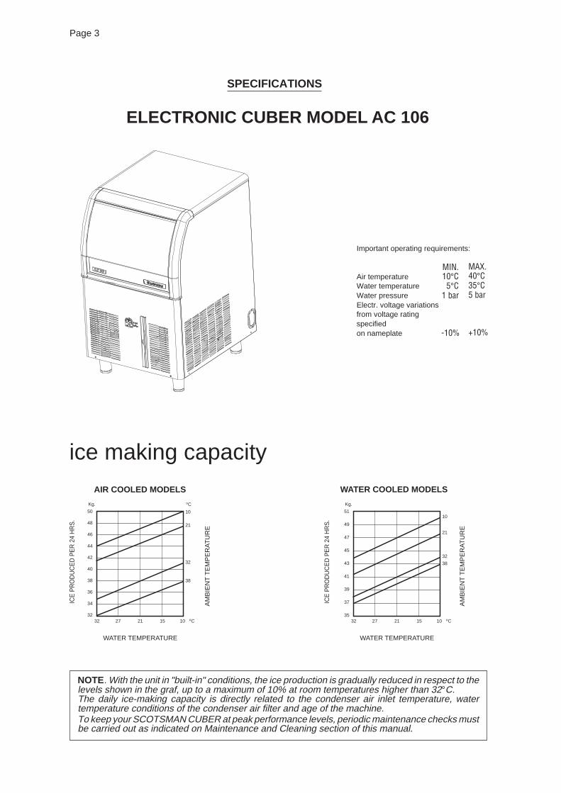
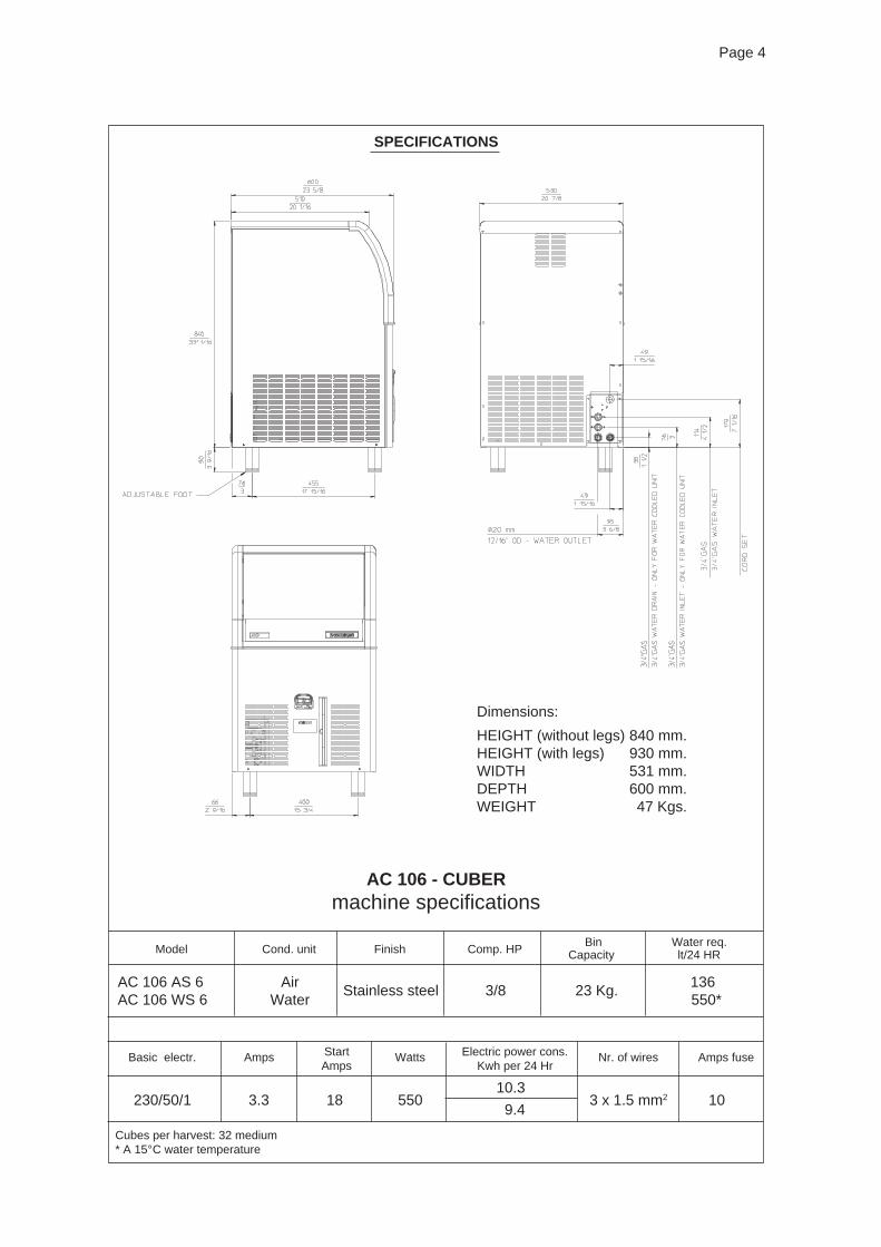

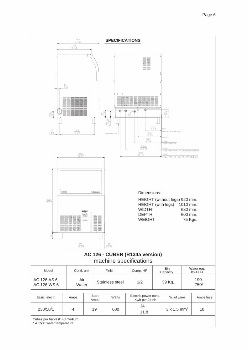

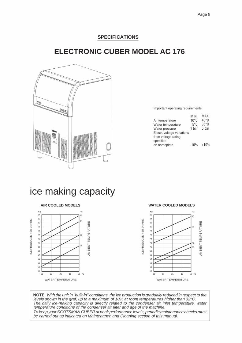
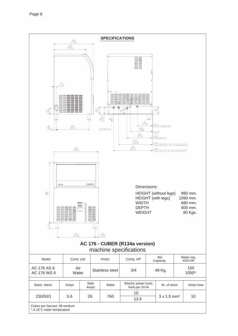


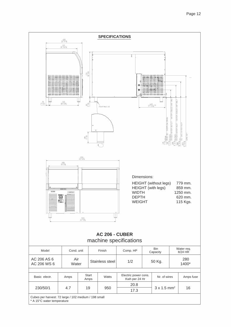
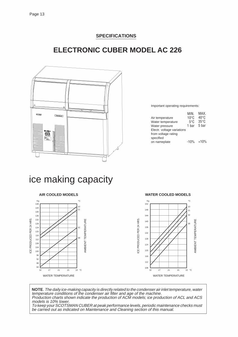
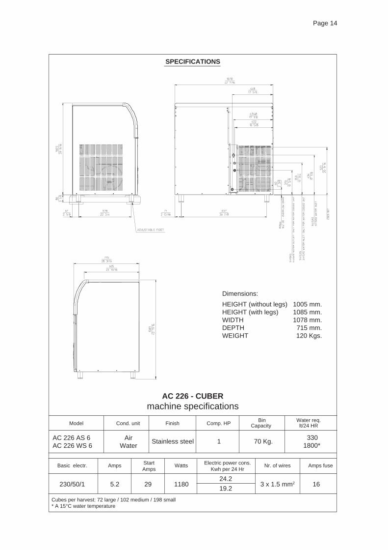


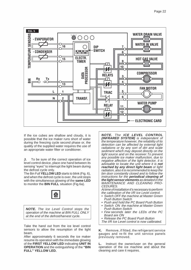


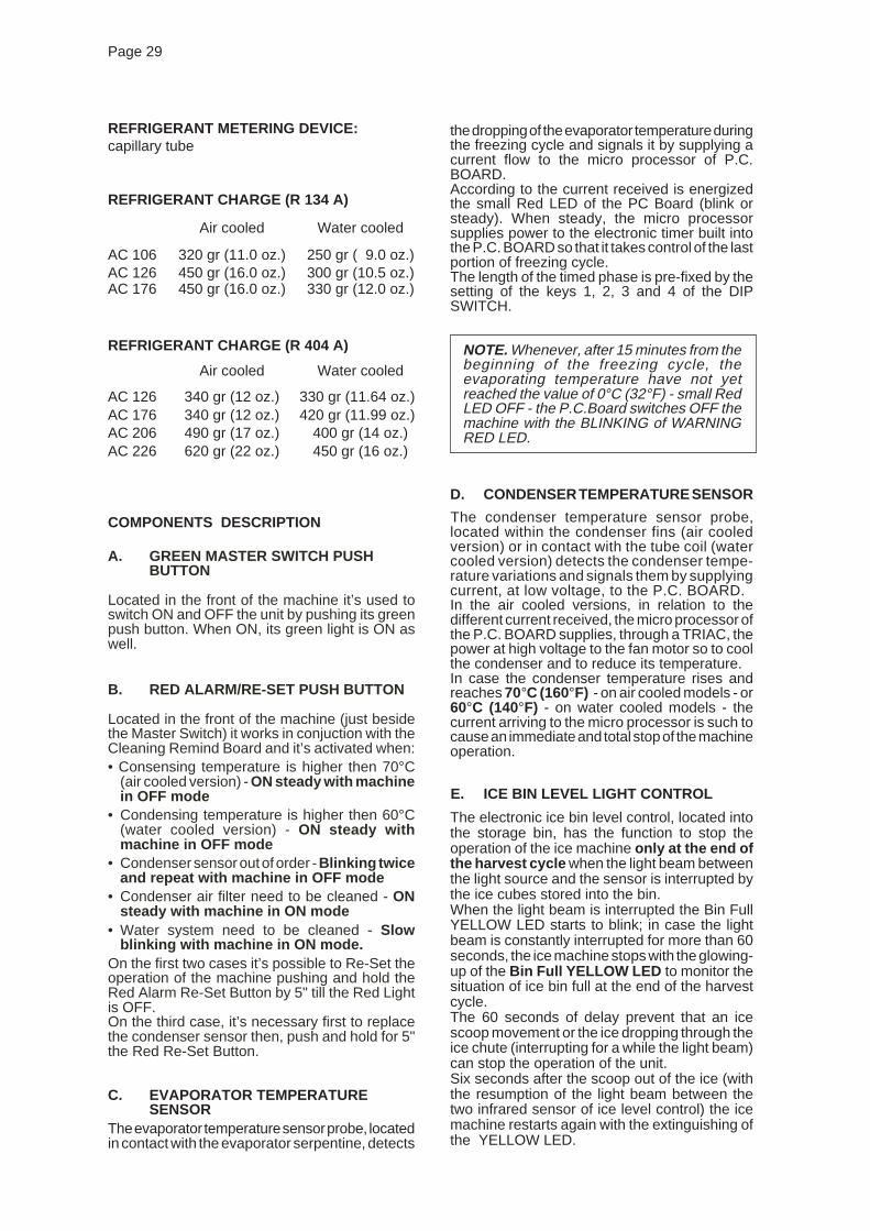
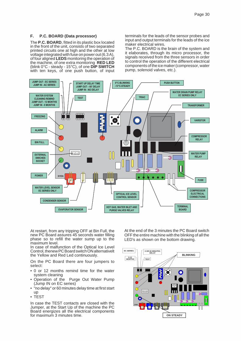


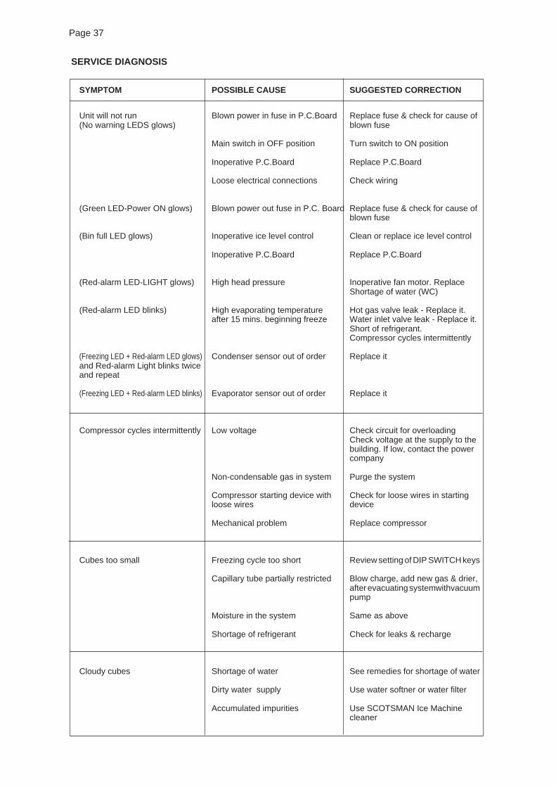
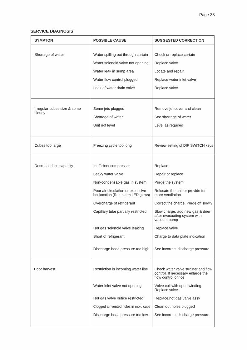

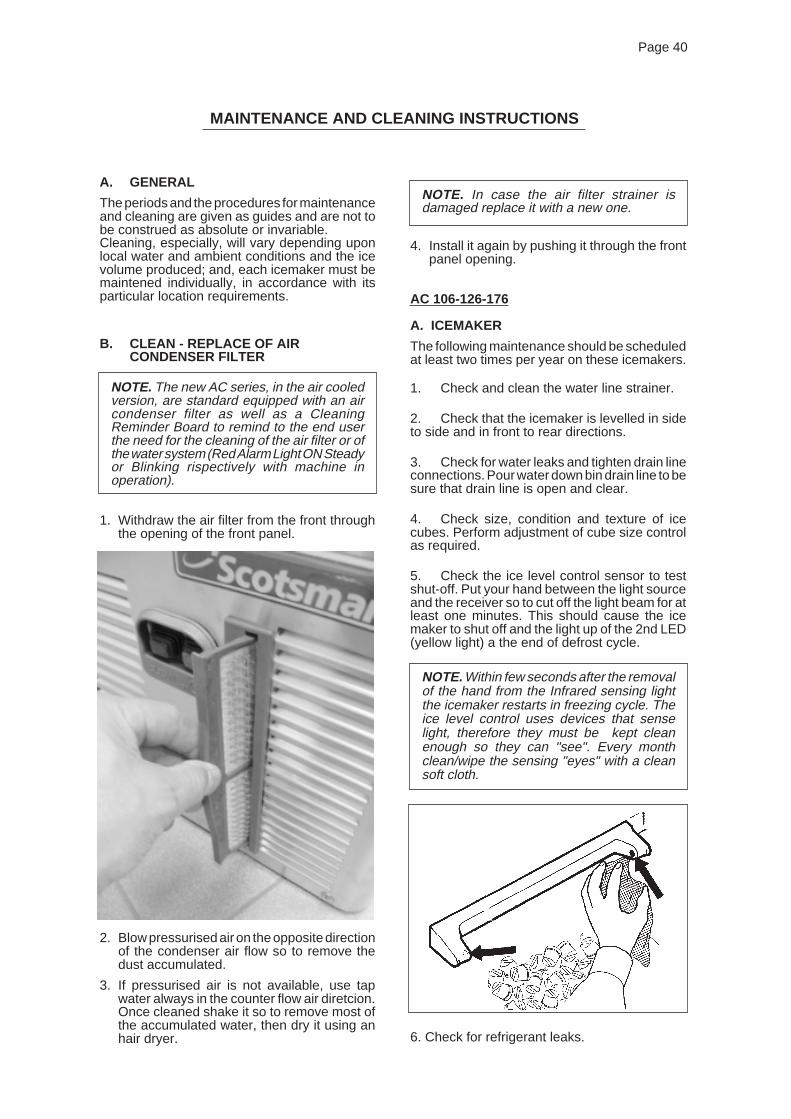
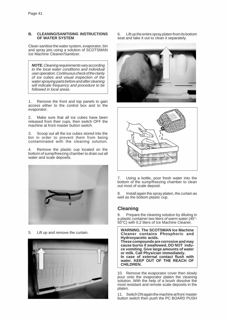

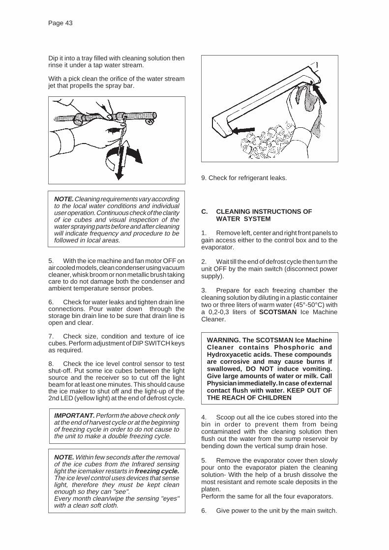
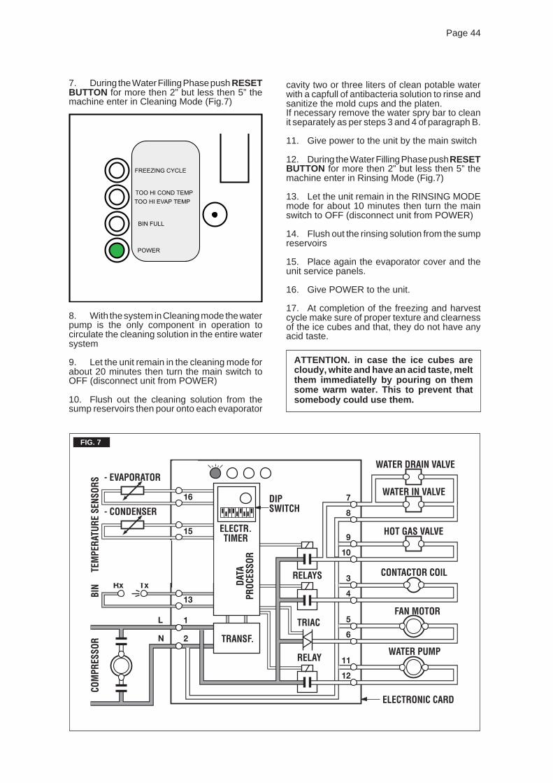
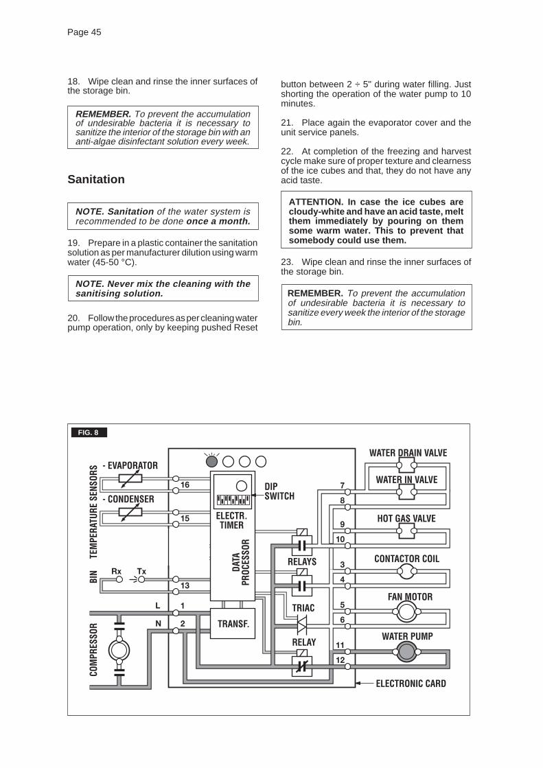

![THALIA - bft-automation.com · PRESET DEFAULT ar sr ac sc ind PARAMETRI Tempo ritardo apertura motore 2 [s] 3 3 3 3 3 3 Tempo di ritardo chiusura motore 1 [s] 3 3 3 3 3 3 Tempo chiusura](https://static.documents.pub/doc/80x56/5c6930f109d3f263648cc312/thalia-bft-preset-default-ar-sr-ac-sc-ind-parametri-tempo-ritardo-apertura.jpg)


