TravelMate 5730/Extensa 5630 Series Service Guide PRINTED IN TAIWAN Service guide files and updates are available on the ACER/CSD web; for more information, please refer to http://csd.acer.com.tw
Transcript
TravelMate 5730/Extensa 5630 SeriesService Guide
PRINTED IN TAIWAN
Service guide files and updates are availableon the ACER/CSD web; for more information,
please refer to http://csd.acer.com.tw
II
Revision HistoryPlease refer to the table below for the updates made on TravelMate 5730/Extensa 5630 Series service guide.
DisclaimerThe information in this guide is subject to change without notice.
Acer Incorporated makes no representations or warranties, either expressed or implied, with respect to the contents hereof and specifically disclaims any warranties of merchantability or fitness for any particular purpose. Any Acer Incorporated software described in this manual is sold or licensed "as is". Should the programs prove defective following their purchase, the buyer (and not Acer Incorporated, its distributor, or its dealer) assumes the entire cost of all necessary servicing, repair, and any incidental or consequential damages resulting from any defect in the software.
Acer is a registered trademark of Acer Corporation.Intel is a registered trademark of Intel Corporation.Pentium and Pentium II/III are trademarks of Intel Corporation.Other brand and product names are trademarks and/or registered trademarks of their respective holders.
IV
ConventionsThe following conventions are used in this manual:
SCREEN MESSAGES Denotes actual messages that appear on screen.
NOTE Gives bits and pieces of additional information related to the current topic.
WARNING Alerts you to any damage that might result from doing or not doing specific actions.
CAUTION Gives precautionary measures to avoid possible hardware or software problems.
IMPORTANT Reminds you to do specific actions relevant to the accomplishment of procedures.
V
PrefaceBefore using this information and the product it supports, please read the following general information.
1. This Service Guide provides you with all technical information relating to the BASIC CONFIGURATION decided for Acer's "global" product offering. To better fit local market requirements and enhance product competitiveness, your regional office MAY have decided to extend the functionality of a machine (e.g. add-on card, modem, or extra memory capability). These LOCALIZED FEATURES will NOT be covered in this generic service guide. In such cases, please contact your regional offices or the responsible personnel/channel to provide you with further technical details.
2. Please note WHEN ORDERING FRU PARTS, that you should check the most up-to-date information available on your regional web or channel. If, for whatever reason, a part number change is made, it will not be noted in the printed Service Guide. For ACER-AUTHORIZED SERVICE PROVIDERS, your Acer office may have a DIFFERENT part number code to those given in the FRU list of this printed Service Guide. You MUST use the list provided by your regional Acer office to order FRU parts for repair and service of customer machines.
6 Productivity keys Three productivity keys give users one-touch access to protection and manageability features for a more secure, smarter and easier way to work.
Chapter 1 5
7 Easy-launch buttons
Buttons for launching frequently used programs.
8 Palmrest Comfortable support area for your hands when you use the computer.
9 Touchpad Touch-sensitive pointing device which functions like a computer mouse.
10 Click buttons (left, center* and right)
The left and right buttons function like the left and right mouse buttons.
*The center button serves as Acer BioProtect fingerprint reader supporting Acer FingerNav 4-way control function (manufacturing option).
11 Acer Bio-Protection fingerprint reader
The center button serves as Acer Bio-Protection fingerprint reader supporting Acer FingerNav 4-way control function (only for certain models).
12/15 Status indicators Light-Emitting Diodes (LEDs) that light up to show the status of the computer's functions and components.
13 Keyboard For entering data into your computer.
14 Power button Turns the computer on and off.
Icon Item Description
6 Chapter 1
Closed Front View
Icon Item Description
1 Latch Locks and releases the lid.
2 5-in-1 card reader Accepts Secure Digital (SD), MultiMediaCard (MMC), Memory Stick (MS), Memory Stick Pro (MS PRO), and xD-Picture Card.
Note: Only one card can operate at any given time.
3 Line-in jack Accepts audio line-in devices (e.g., audio CD player, stereo walkman, mp3 player)
4 Microphone jack Accepts inputs from external microphones.
5 Headphones/speaker/line-out jack.
Connects to audio line-out devices (e.g., speakers, headphones).
6 Bluetooth communication switch
Enable/disable the Bluetooth function. (manufacturing option).
7 Wireless communication switch
Enable/disable the wireless function. (manufacturing option).
Chapter 1 7
Left View
Right View
# Icon Item Description
1 Kensington lock slot Connects to a Kensington-compatible computer security lock.
2 Acer EasyPort IV connector
Connects to Acer EasyPort IV(only for certain models).
3 External display (VGA) port
Connects to a display device (e.g., external monitor, LCD projector).
4 Ethernet (RJ-45) port
Connects to an Ethernet 10/100/1000-based network.
5 HDMI port Supports high definition digital video connections (only for certain models).
6 Two USB 2.0 ports Connect to USB 2.0 devices (e.g., USB mouse, USB camera).
7 PC Card slot Accepts one Type II PC Card.
8 ExpressCard/54 slot
Accepts one ExpressCard/54 module.
9 PC Card slot eject button
Ejects the PC Card from the slot.
Icon Item Description
1 Optical drive Internal optical drive; accepts CDs or DVDs.
2 Optical disk access indicator
Lights up when the optical drive is active.
3 Optical drive eject button
Ejects the optical disk from the drive.
8 Chapter 1
4 Emergency eject hole Ejects the optical drive tray when the computer is turned off.Note: Insert a paper clip to the emergency eject hole to eject the optical drive tray when the computer is off.
Icon Item Description
Chapter 1 9
Rear View
# Icon Item Description
1 USB 2.0 port Connects to USB 2.0 devices (e.g., USB mouse, USB camera).
2 USB 2.0/ e SATAport
Connects to USB 2.0 or eSATA devices(only for certain models).Note: If you plug an eSATA device you will have three USB ports available in the mean time.
3 Modem (RJ-11) port
Connects to a phone line.
4 DC-in jack Connects to an AC adapter.
5 Ventilation slots Enable the computer to stay cool, even after prolonged use.
10 Chapter 1
Bottom View
Icon Item Description
1 Hard disk bay Houses the computer's hard disk (secured with screws).
2 Acer DASP (Disk Anti-Shock Protection)
Protects the hard disk drive from shocks and bumps (only for certain models).
3 Ventilation slots Enable the computer to stay cool, even after prolonged use.
4 Memory compartment
Houses the computer's main memory.
5 Battery lock Locks the battery in position.
6 Battery release latch
Releases the battery for removal.
7 Battery bay Houses the computer's battery pack.
Chapter 1 11
IndicatorsThe computer has several easy-to-read status indicators. The front panel indicators are visible even when the computer cover is closed.
NOTE: 1. Charging: The light shows amber when the battery is charging. 2. Fully charged: The light shows green when in AC mode.
Easy-Launch ButtonsLocated beside the keyboard are application buttons. These buttons are called easy-launch buttons. They are: WLAN, Internet, email, Bluetooth, Arcade and Acer Empowering Technology.
The mail and Web browser buttons are pre-set to email and Internet programs, but can be reset by users. To set the Web browser, mail and programmable buttons, run the Acer Launch Manager.You can access the Launch Manager by clicking on Start, All Programs, and then Launch Manager to start the application.
Icon Function Description
HDD Indicates when the hard disk drive is active.
Num Lock Lights up when Num Lock is activated.
Caps Lock Lights up when Caps Lock is activated.
Power Indicates the computer's power status.
Battery Indicates the computer's battery status.
Bluetooth(Manufacturing option)
Indicates the status of Bluetooth communication.
Wireless LAN(Manufacturing option)
Indicates the status of wireless LAN communication.
Touchpad Basics (with fingerprint reader)The following items show you how to use the touchpad with Acer Bio-Protection fingerprint reader.
� Move your finger across the touchpad (2) to move the cursor.
� Press the left (1) and right (4) buttons located beneath the touchpad to perform selection and execution functions. These two buttons are similar to the left and right buttons on a mouse. Tapping on the touchpad is the same as clicking the left button.
� Use Acer Bio-Protection fingerprint reader (3) supporting Acer FingerNav 4-way control function (only for certain models) to scroll up or down and move left or right a page. This fingerprint reader or button mimics your cursor pressing on the right scroll bar of Windows applications.
Touchpad basics (with two-click buttons)The following items show you how to use the touchpad with two-click buttons.
� Move your finger across the touchpad (1) to move the cursor.
Function Left button (1) Right button (4) Main touchpad (2) Center button (3)
Execute Quickly click twice.
Tap twice (at the same speed as double-clicking a mouse button).
Select Click once. Tap once.
Drag Click and hold, then use finger on the touchpad to drag the cursor.
Tap twice (at the same speed as double-clicking a mouse button); rest your finger on the touchpad on the second tap and drag the cursor.
Access context menu
Click once.
Scroll Swipe up/down/left/right using Acer FingerNav 4-way control function (Manufacturing option).
1 2 3 4
1 2 3
Chapter 1 13
� Press the left (2) and right (3) buttons located beneath the touchpad to perform selection and execution functions. These two buttons are similar to the left and right buttons on a mouse. Tapping on the touchpad is the same as clicking the left button.
NOTE: Illustrations for reference only. The exact configuration of your PC depends on the model purchased.
NOTE: When using the touchpad, keep it — and your fingers — dry and clean. The touchpad is sensitive to finger movement; hence, the lighter the touch, the better the response. Tapping harder will not increase the touchpad's responsiveness.
NOTE: By default, vertical and horizontal scrolling is enabled on your touchpad. It can be disabled under Mouse settings in Windows Control Panel.
Function Left button (2) Right button (3) Main touchpad (1)
Execute Quickly click twice. Tap twice (at the same speed as double-clicking a mouse button).
Select Click once. Tap once.
Drag Click and hold, then use finger on the touchpad to drag the cursor.
Tap twice (at the same speed as double-clicking a mouse button); rest your finger on the touchpad on the second tap and drag the cursor.
Access context menu
Click once.
14 Chapter 1
Using the KeyboardThe keyboard has full-sized keys and an embedded numeric keypad, separate cursor, lock, Windows, function and special keys.
Lock Keys and embedded numeric keypadThe keyboard has three lock keys which you can toggle on and off.
The embedded numeric keypad functions like a desktop numeric keypad. It is indicated by small characters located on the upper right corner of the key caps. To simplify the keyboard legend, cursor-control key symbols are not printed on the keys.
Lock key Description
Caps Lock When Caps Lock is on, all alphabetic characters typed are in uppercase.
Num Lock <Fn> + <F11>
When Num Lock is on, the embedded keypad is in numeric mode. The keys function as a calculator (complete with the arithmetic operators +, -, *, and /). Use this mode when you need to do a lot of numeric data entry. A better solution would be to connect an external keypad.
NOTE: <Fn> + <F11> works only for certain models.
Scroll Lock <Fn> + <F12>
When Scroll Lock is on, the screen moves one line up or down when you press the up or down arrow keys respectively. Scroll Lock does not work with some applications.
Desired access Num Lock on Num Lock off
Number keys on embedded keypad
Type numbers in a normal manner.
Cursor-control keys on embedded keypad
Hold <Shift> while using cursor-control keys.
Hold <Fn> while using cursor-control keys.
Main keyboard keys Hold <Fn> while typing letters on embedded keypad.
Type the letters in a normal manner.
Chapter 1 15
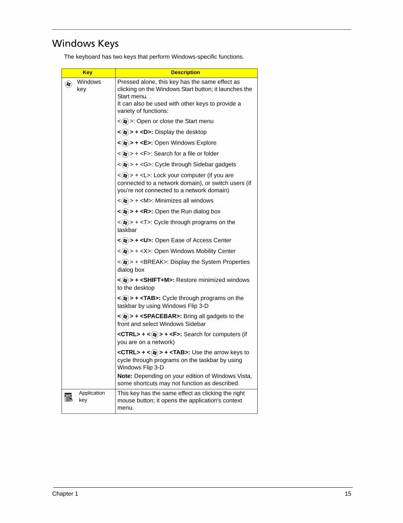
Windows KeysThe keyboard has two keys that perform Windows-specific functions.
Key Description
Windows key
Pressed alone, this key has the same effect as clicking on the Windows Start button; it launches the Start menu. It can also be used with other keys to provide a variety of functions:
< >: Open or close the Start menu
< > + <D>: Display the desktop
< > + <E>: Open Windows Explore
< > + <F>: Search for a file or folder
< > + <G>: Cycle through Sidebar gadgets
< > + <L>: Lock your computer (if you are connected to a network domain), or switch users (if you're not connected to a network domain)
< > + <M>: Minimizes all windows
< > + <R>: Open the Run dialog box
< > + <T>: Cycle through programs on the taskbar
< > + <U>: Open Ease of Access Center
< > + <X>: Open Windows Mobility Center
< > + <BREAK>: Display the System Properties dialog box
< > + <SHIFT+M>: Restore minimized windows to the desktop
< > + <TAB>: Cycle through programs on the taskbar by using Windows Flip 3-D
< > + <SPACEBAR>: Bring all gadgets to the front and select Windows Sidebar
<CTRL> + < > + <F>: Search for computers (if you are on a network)
<CTRL> + < > + <TAB>: Use the arrow keys to cycle through programs on the taskbar by using Windows Flip 3-DNote: Depending on your edition of Windows Vista, some shortcuts may not function as described.
Application key
This key has the same effect as clicking the right mouse button; it opens the application's context menu.
16 Chapter 1
Hot KeysThe computer employs hotkeys or key combinations to access most of the computer’s controls like screen brightness, volume output and the BIOS utility.
To activate hot keys, press and hold the <Fn> key before pressing the other key in the hotkey combination.
Launches Acer ePower Management in Acer Empowering Technology.
<Fn> + <F4> Sleep Puts the computer in Sleep mode.
<Fn> + <F5> Display toggle Switches display output between the display screen, external monitor (if connected) and both.
<Fn> + <F6> Screen blank Turns the display screen backlight off to save power. Press any key to return.
<Fn> + <F7> Touchpad toggle Turns the internal touchpad on and off.
<Fn> + <F8> Speaker toggle Turns the speakers on and off.
<Fn> + < > Brightness up Increases the screen brightness.
<Fn> + < > Brightness down Decreases the screen brightness.
<Fn> + < > Volume up Increases the sound volume(only for certain models).
<Fn> + < > Volume down Decreases the sound volume(only for certain models).
Chapter 1 17
Special Key (only for certain models)You can locate the Euro symbol and the US dollar sign at the upper-center and/or bottom-right of your keyboard.
The Euro symbol
1. Open a text editor or word processor.
2. Either press < > at the bottom-right of the keyboard, or hold <Alt Gr> and then press the <5> key at the upper-center of the keyboard.
NOTE: Some fonts and software do not support the Euro symbol. Please refer to www.microsoft.com/typography/faq/faq12.htm for more information.
The US dollar sign
1. Open a text editor or word processor.
2. Either press < > at the bottom-right of the keyboard, or hold <Shift> and then press the <4> key at the upper-center of the keyboard.
NOTE: This function varies according to the language settings.
18 Chapter 1
Acer Empowering TechnologyThe Empowering Technology toolbar makes it easy for you to access frequently used functions and manage your new Acer system. Activated by pressing the Empowering Key, it provides access to the following utilities:
NOTE: The following content is for general reference only. Actual product specifications may vary.
� Acer eDataSecurity Management protects data with passwords and encryption (only for certain models).
� Acer ePower Management optimizes battery usage via customizable power plans.
� Acer eRecovery Management backs up and recovers data flexibly, reliably and completely.
� Acer eSettings Management accesses system information and adjusts settings easily.
For more information, right-click on the Empowering Technology toolbar, then select Help. For help with a
particular utility, launch the utility and click the icon at the bottom of the active window.
Launching Acer Empowering Technology
To launch Acer Empowering Technology:
1. Press the Empowering Key to display the Acer Empowering Technology toolbar on the desktop.
2. To hide the toolbar, press the Empowering Key again or click the hide button on the toolbar.
You may also launch Acer Empowering Technology by running the program from the Acer Empowering
Technology program group in the Start menu, or by double-clicking the icon if you have created a
desktop shortcut.
To launch Acer Empowering Technology applications:
1. On the Acer Empowering Technology toolbar, click the icon that corresponds to the application you want to launch.
2. When you mouse over an application icon, a quick menu appears below the toolbar. The quick menu allows you to perform certain tasks simply and quickly.
3. You may also run the application by selecting it from the Acer Empowering Technology program group in the Start menu.
Chapter 1 19
Empowering Technology passwordYou must set the Empowering Technology password to use the password protection feature of Acer eRecovery Management to protect your data.
To set the Empowering Technology password:
1. Launch Acer eRecovery Management.
2. Click the Restore tab.
3. Click Password settings. The Empowering Technology Password Center dialogue box pops up.
4. Click Create a new password.
5. In the Create a New Password dialogue box, key in and confirm your password in the appropriate boxes. Your password should have a minimum of 4 and a maximum of 12 characters.
6. Enter a password hint that will help you remember your password.
7. Make sure the box Use for Acer eRecovery Management is checked.
8. Click OK to set the password.
20 Chapter 1
Acer ePower Management
Acer ePower Management features a straightforward user interface for configuring your power management options. To access this utility, select Acer ePower Management from the Empowering Technology toolbar, run the program from the Acer Empowering Technology program group in Start menu, or right-click the Windows power icon in the system tray and select Acer ePower Management.
Using power plans
Acer ePower Management comes with three predefined power plans: Balanced, High performance and Power saver. You can also create customized power plans. You can create, switch between, edit, delete and restore power plans, as described below.
View and adjust settings for On Battery and Plugged In modes by clicking the appropriate tabs. For more
power options, click in the Acer ePower Management utility, or right-click the Windows power icon in the
system tray and select Power Options.
NOTE: You cannot delete the predefined power plans.
To create a new power plan:
Creating customized power plans allows you to save and quickly switch to a personalized set of power options.
1. Click the New power plan option or icon .
2. Enter a name for your new power plan.
3. Choose a predefined power plan to base your customized plan on.
4. If necessary, change the display, sleep and hibernation settings you want your computer to use.
5. Click OK to save your new power plan.
To switch between power plans:
1. Mouse over the Acer ePower Management application on the Acer Empowering Technology toolbar. The quick menu appears. Select the power plan you want to switch to.
2. You may also switch between power plans by launching the Acer ePower Management application. Select the power plan you wish to switch to, then click Apply.
To edit a power plan:
Editing a power plan allows you to adjust system settings like LCD brightness and CPU speed.
1. Switch to the power plan you wish to edit.
2. Adjust settings as required.
3. Click Apply to save your new settings.
To delete a power plan:
You cannot delete the power plan you are currently using. If you want to delete the active power plan, switch to another one first.
1. Select the power plan you wish to delete.
2. Click the Delete Power Plan icon.
Battery status
1. The quick menu shows the remaining battery life based on current usage.
2. You can also launch the Acer ePower Management application and refer to the Battery status panel located just below the power plans.
Chapter 1 21
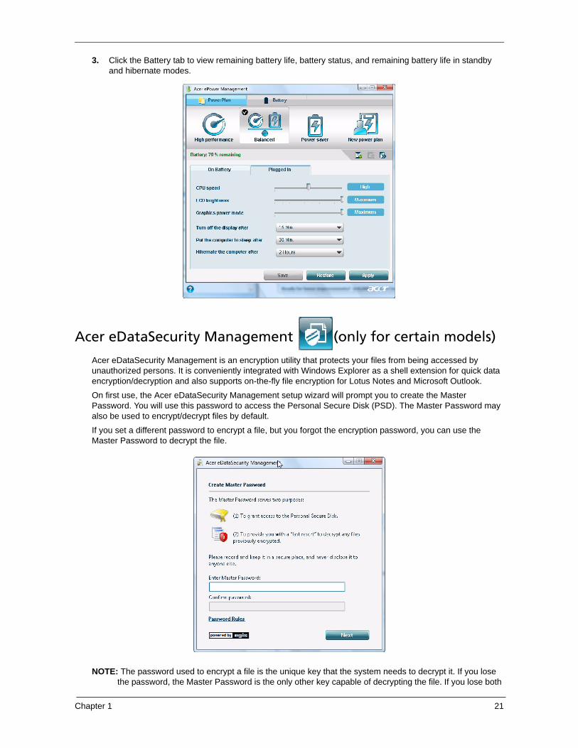
3. Click the Battery tab to view remaining battery life, battery status, and remaining battery life in standby and hibernate modes.
Acer eDataSecurity Management (only for certain models)
Acer eDataSecurity Management is an encryption utility that protects your files from being accessed by unauthorized persons. It is conveniently integrated with Windows Explorer as a shell extension for quick data encryption/decryption and also supports on-the-fly file encryption for Lotus Notes and Microsoft Outlook.
On first use, the Acer eDataSecurity Management setup wizard will prompt you to create the Master Password. You will use this password to access the Personal Secure Disk (PSD). The Master Password may also be used to encrypt/decrypt files by default.
If you set a different password to encrypt a file, but you forgot the encryption password, you can use the Master Password to decrypt the file.
NOTE: The password used to encrypt a file is the unique key that the system needs to decrypt it. If you lose the password, the Master Password is the only other key capable of decrypting the file. If you lose both
22 Chapter 1
passwords, there will be no way to decrypt your encrypted file! Be sure to safeguard all related passwords!
Acer eRecovery Management
Acer eRecovery Management is a versatile backup utility. It allows you to create full or incremental backups, burn the factory default image to optical disc, and restore from previously created backups or reinstall applications and drivers. By default, user-created backups are stored to the D:\ drive.
Acer eRecovery Management provides you with:
� Backup:
�Back up factory default to CD/DVD
�Back up drivers and applications to CD/DVD
�Create user backup
�Manage user backups
� Restore:
�Restore system to factory default
�Reinstall applications/drivers
�Restore system from user backup
�Password settings
To use the password protection feature of Acer eRecovery Management to protect your data, you must first set the Empowering Technology password. To set the password, refer to the section "Empowering Technology password".
Chapter 1 23
NOTE: If your computer did not come with a Recovery CD or System CD, please use Acer eRecovery Management's Backup factory default to CD/DVD feature to burn a backup image to CD or DVD. To ensure the best results when recovering your system using a CD or Acer eRecovery Management, detach all peripherals (except the external Acer ODD, if your computer has one), including your Acer ezDock.
24 Chapter 1
Acer eSettings Management
Acer eSettings Management allows you to inspect hardware specifications, set BIOS passwords and modify boot options.
Acer eSettings Management also:
� Provides a simple graphical user interface for navigation.
� Prints and saves hardware specifications.
� Lets you set an asset tag for your system.
Chapter 1 25
Windows Mobility Center
The Windows Mobility Center collects key mobile-related system settings in one easy-to-find place, so you can quickly configure your Acer system to fit the situation as you change locations, networks or activities. Settings include display brightness, volume, power plan, wireless networking on/off, external display settings, synchronization status and presentation settings.
Windows Mobility Center also includes Acer-specific settings like sharing folders overview/sharing service on or off, Bluetooth Add Device (if applicable), and a shortcut to the Acer user guide, drivers and utilities.
To launch Windows Mobility Center:
� Use the shortcut key < > + <X>.
� Start Windows Mobility Center from the Control panel.
� Start Windows Mobility Center from the Accessories program group in the Start menu.
� Launch Windows Mobility Center by right-clicking in the system tray and select Windows Mobility
Center.
26 Chapter 1
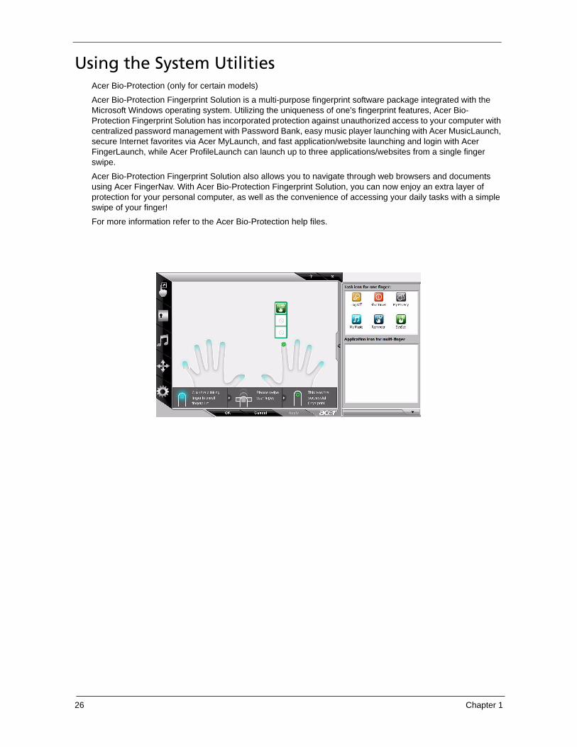
Using the System UtilitiesAcer Bio-Protection (only for certain models)
Acer Bio-Protection Fingerprint Solution is a multi-purpose fingerprint software package integrated with the Microsoft Windows operating system. Utilizing the uniqueness of one's fingerprint features, Acer Bio-Protection Fingerprint Solution has incorporated protection against unauthorized access to your computer with centralized password management with Password Bank, easy music player launching with Acer MusicLaunch, secure Internet favorites via Acer MyLaunch, and fast application/website launching and login with Acer FingerLaunch, while Acer ProfileLaunch can launch up to three applications/websites from a single finger swipe.
Acer Bio-Protection Fingerprint Solution also allows you to navigate through web browsers and documents using Acer FingerNav. With Acer Bio-Protection Fingerprint Solution, you can now enjoy an extra layer of protection for your personal computer, as well as the convenience of accessing your daily tasks with a simple swipe of your finger!
For more information refer to the Acer Bio-Protection help files.
Chapter 1 27
Acer GridVista (dual-display compatible)NOTE: This feature is only available on certain models.
To enable the dual monitor feature of the notebook, first ensure that the second monitor is connected, then select Start, Control Panel, Display and click on Settings. Select the secondary monitor (2) icon in the display box and then click the check box Extend my windows desktop onto this monitor. Finally, click Apply to confirm the new settings and click OK to complete the process.
Acer GridVista is a handy utility that offers four pre-defined display settings so you can view multiple windows on the same screen. To access this function, please go to Start>All Programs and click on Acer GridVista. You may choose any one of the four display settings indicated below:
Double (vertical), Triple (primary at left), Triple (primary at right), or Quad Acer Gridvista is dual-display compatible, allowing two displays to be partitioned independently.
Acer Gridvista is dual-display compatible, allowing two displays to be partitioned independently.
AcerGridVista is simple to set up:
1. Run Acer GridVista and select your preferred screen configuration for each display from the task bar.
2. Drag and drop each window into the appropriate grid.
3. Enjoy the convenience of a well-organized desktop.
Note:
Start Control Panel Display
Settings (2)
Extend my windows desktop onto this monitor
Apply OK
Start All Programs Acer GridVista
28 Chapter 1
NOTE: Please ensure that the resolution setting of the second monitor is set to the manufacturer's recommended value.
Chapter 1 29
Hardware Specifications and ConfigurationsProcessor
Throttling 50%: On= 99 C; OFF=93 C
OS shut down at 105 C; H/W shot down at 110 .C
Item Specification
CPU type Intel® Core™2 Duo Mobile Processor P8400 (2.26G), P8600 (2.4 G), P9500 (2.53G), T9400 (2.53G), T9600 (2.8G)
Core logic Mobile Intel® 945 Express Chipset
CPU package Socket B (P8400, P8600, P9500) and Socket P (T9400, T9600)
CPU core voltage 1.0375V to 1.3V
CPU Fan True Value Table
DTS(degree C) Fan Speed (rpm) Acoustic Level (dBA)
45-50 0-3000 29
55-66 0-3300 33
68-74 3300-3800 38
78-83 3800-4100 40
86-91 4100-4800 40
BIOS
Item Specification
BIOS vendor Phoenix
BIOS Version 1.04c
System Memory
Item Specification
Memory controller Built-in
Memory size 0MB (no on-board memory)
DIMM socket number 2 sockets
Supports memory size per socket 2048MB
Supports maximum memory size 4G for 64bit OS (with two 2GB SODIMM)
Supports DIMM type DDR 2 Synchronous DRAM
Supports DIMM Speed 667 MHz
Supports DIMM voltage 1.8V and 0.9V
Supports DIMM package 200-pin soDIMM
Memory module combinations You can install memory modules in any combinations as long as they match the above specifications.
° °
° °
30 Chapter 1
NOTE: Above table lists some system memory configurations. You may combine DIMMs with various capacities to form other combinations. On above table, the configuration of slot 1 and slot 2 could be reversed.
Memory Combinations
Slot 1 Slot 2 Total Memory
0MB 256MB 256MB
0MB 512MB 512MB
0MB 1024MB 1024MB
0MB 2048MB 2048MB
256MB 256MB 512MB
256MB 512MB 768MB
256MB 1024MB 1280MB
256MB 2048MB 2304MB
512MB 256MB 768MB
512MB 512MB 1024MB
512MB 1024MB 1536MB
512MB 2048MB 2560MB
1024MB 0MB 1024MB
1024MB 256MB 1280MB
1024MB 512MB 1536MB
1024MB 1024MB 2048MB
1024MB 2048MB 3072MB
2048MB 0MB 2048MB
2048MB 256MB 2304MB
2048MB 512MB 2560MB
2048MB 1024MB 3072MB
2048MB 2048MB 4096MB
Item Specification
LAN Chipset Broadcom BCM5764/Broadcom BCM5765
Supports LAN protocol 10/100/1000 Mbps
LAN connector type RJ45
LAN connector location Left side
Features Integrated 10/100 BASE-T transceiver
Wake on LAN support compliant with ACPI 2.0PCI v2.2
Bluetooth Interface
Item Specification
Chipset Foxconn Bluetooth FOX_BRM_2.0 F/W 300
Data throughput 723 bps (full speed data rate)
Protocol Bluetooth 1.1 (Upgradeable to Bluetooth 1.2 when SIG specification is ratified).
Interface USB 1.1
Chapter 1 31
Connector type USB
Wireless Module 802.11b/g
Item Specification
Chipset WLAN 802.11ABGN SHIRLEYPEAK1*2
Data throughput 11~54 Mbps, up to 270 Mbps for Draft-N
Protocol 802.11b+g, Draft-N
Interface PCI bus (mini PCI socket for wireless module)
PCMCIA/ 5 in 1 Card Reader JMicron Cardreader JMB385
Audio Codec Audio Azalia(ALC888S)
Keyboard
Item Specification
Keyboard controller NS PC97541V
34 Chapter 1
Total number of keypads 84-/85-key
Windows logo key Yes
Internal & external keyboard work simultaneously
Plug USB keyboard to the USB port directly: Yes
Battery
Item Specification
Vendor Panasonic/Sanyo/Sony/Simplo
Battery Type Li-ion
Pack capacity 6Cell 4400 MAH/8Cell 4800 MAH
Number of battery cell 6/8
Package configuration 3 cells in series, 2 series in parallel4 cells in series, 2 series in parallel
LCD 15.4” inch
Item Specification
Vendor & model name CMO/AUO/LG
Screen Diagonal (mm) 15.4 inches
Display resolution (pixels) 1280 x 800 WXGA
Pixel Pitch 0.204 x 0.204
Pixel Arrangement R.G.B. Vertical Stripe
Display Mode Normally White
Typical White Luminance (NIT)also called Brightness
220
Luminance Uniformity 1.25 max.
Contrast Ratio 400 typical
Response Time msec 8
Nominal Input Voltage VDD +3.3V
Viewing Angle (degree)
Horizontal: Right/Left
Vertical: Upper/Lower
45/45
15/35
Temperature Range( C)
Operating
Storage (shipping)
0 to +50
-40 to +60
AC Adaptor
Item Specification
Input 100-240V~ 1.5A, 50-60Hz/
Output 19V 4.74A 90W/19V 3.42A 65W
Keyboard
Item Specification
°
Chapter 1 35
System Power Management
ACPI mode Power Management
Mech. Off (G3) All devices in the system are turned off completely.
Soft Off (G2/S5) OS initiated shutdown. All devices in the system are turned off completely.
Working (G0/S0) Individual devices such as the CPU and hard disc may be power managed in this state.
Suspend to RAM (S3) CPU set power down
VGA Suspend
PCMCIA SuspendAudio Power Down
Hard Disk Power Down
CD-ROM Power Down
Super I/O Low Power mode
Save to Disk (S4) Also called Hibernation Mode. System saves all system states and data onto the disc prior to power off the whole system.
36 Chapter 1
Chapter 2 37
BIOS Setup UtilityThe BIOS Setup Utility is a hardware configuration program built into your computer’s BIOS (Basic Input/Output System).
Your computer is already properly configured and optimized, and you do not need to run this utility. However, if you encounter configuration problems, you may need to run Setup. Please also refer to Chapter 4 Troubleshooting when problem arises.
To activate the BIOS Utility, press F2 during POST (when “Press <F2> to enter Setup” message is prompted on the bottom of screen).
Press F2 to enter setup. The default parameter of F12 Boot Menu is set to “disabled”. If you want to change boot device without entering BIOS Setup Utility, please set the parameter to “enabled”.
Press <F12> during POST to enter multi-boot menu. In this menu, user can change boot device without entering BIOS SETUP Utility.
Phoen i x Secu reCo re ( tm ) Se tup U t i l i t yM a i n
CPU Type :C P U Sp e e d :IDE0 Mode l Name :IDE0 Se r i a l Numbe r :ATAP I Mode l Name :Sys tem BIOS Ve rs i on :VGA BIOS Ve rs i on :KBC Ve rs i on :Se r i a l Numbe r :Asse t Tag Number :P roduc t Name :Manu fac tu re r Name :UUID :
I n t e l (R ) Co re (TM)2 Duo CPU T9400 @ 2.53 GHz2 .53 GHzXXXXXXXXXXX- (XX)XXXXXXXXXXXXXXXXXXX-XXX XX-XXXX- (XX)VX .XXXX-XXX XXXXXX.XXX .XXX .XXX .XXXXXXXX.XXXXXXXXXXXXXXXXXXXXXXXXXN o n eAsp i r e 5930Ace rXXXxXxXX-xXxX-XXxx -xXXx -xXXxXXxXxxXX
F1
Esc
H e l pEx i t
Se lec t I t emS e l e c t Me n u
C h a n g e Va l u e sSe lec t Sub -Menu
- / +
En te r
F9
F10
Se tup De fau l t sSave and Ex i t
I n f o rma t i on Secu r i t y Boo t Ex i t
System Utilities
Chapter 2
38 Chapter 2
Navigating the BIOS Utility
There are six menu options: Information, Main, Security, Boot, and Exit.
Follow these instructions:
� To choose a menu, use the left and right arrow keys.
� To choose an item, use the up and down arrow keys.
� To change the value of a parameter, press F5 or F6.
� A plus sign (+) indicates the item has sub-items. Press Enter to expand this item.
� Press Esc while you are in any of the menu options to go to the Exit menu.
� In any menu, you can load default settings by pressing F9. You can also press F10 to save any changes made and exit the BIOS Setup Utility.
NOTE: You can change the value of a parameter if it is enclosed in square brackets. Navigation keys for a particular menu are shown on the bottom of the screen. Help for parameters are found in the Item Specific Help part of the screen. Read this carefully when making changes to parameter values. Please note that system information is subject to different models.
Chapter 2 39
Information
The Information screen displays a summary of your computer hardware information.
NOTE: The system information is subject to different models.
Parameter Description
CPU Type This field shows the CPU type and speed of the system.
CPU Speed This field shows the speed of the CPU.
IDE0 Model Name This field shows the model name of HDD installed on primary IDE master.
IDE0 Serial Number This field displays the serial number of HDD installed on primary IDE master.
ATAPI Model Name This field shows the model name of the Optical device installed in the system.
System BIOS Version Displays system BIOS version.
VGA BIOS Version This field displays the VGA firmware version of the system.
KBC Ver This field shows the keyboard
Serial Number This field displays the serial number of this unit.
Asset Tag Number This field displays the asset tag number of the system.
Product Name This field shows product name of the system.
Manufacturer Name This field displays the manufacturer of this system.
UUID Number Universally Unique Identifier (UUID) is an identifier standard used in software construction, standardized by the Open Software Foundation (OSF) as part of the Distributed Computing Environment (DCE).
Phoen i x Secu reCo re ( tm ) Se tup U t i l i t yM a i n
CPU Type :C P U Sp e e d :IDE0 Mode l Name :IDE0 Se r i a l Numbe r :ATAP I Mode l Name :Sys tem BIOS Ve rs i on :VGA BIOS Ve rs i on :KBC Ve rs i on :Se r i a l Numbe r :Asse t Tag Number :P roduc t Name :Manu fac tu re r Name :UUID :
I n t e l (R ) Co re (TM)2 Duo CPU T9400 @ 2.53 GHz2 .53 GHzXXXXXXXXXXX- (XX)XXXXXXXXXXXXXXXXXXX-XXX XX-XXXX- (XX)VX .XXXX-XXX XXXXXX.XXX .XXX .XXX .XXXXXXXX.XXXXXXXXXXXXXXXXXXXXXXXXXN o n eAsp i r e 5930Ace rXXXxXxXX-xXxX-XXxx -xXXx -xXXxXXxXxxXX
F1
Esc
H e l pEx i t
Se lec t I t emS e l e c t Me n u
C h a n g e Va l u e sSe lec t Sub -Menu
- / +
En te r
F9
F10
Se tup De fau l t sSave and Ex i t
I n f o rma t i on Secu r i t y Boo t Ex i t
40 Chapter 2
Main
The Main screen allows the user to set the system time and date as well as enable and disable boot option and recovery.
NOTE: The screen above is for your reference only. Actual values may differ.
Phoen i x Secu reCo re ( tm ) Se tup U t i l i t yM a i n
I t em Spec i f i c He lp
<Tab> , <Sh i f t -Tab> , o r<En te r> se lec t s f i e l d .
Sys tem Ti me :Sys tem Da te :
Sys tem Memory :Ex tended Memory :V ideo Memory :
Qu ie t Boo t :Ne two rk Boo t :F12 Boo t Menu :D2D Recove ry :SATAMode
F1
Esc
H e l pEx i t
Se lec t I t emS e l e c t Me n u
C h a n g e Va l u e sSe lec t Sub -Menu
- / +
En te r
F9
F10
Se tup De fau l t sSave and Ex i t
I n f o rma t i on Secu r i t y B o o t Ex i t
[ ][ ]
: 1 0 :1 004 / 2 8 /2 0 0 8
640 KB4093 MB512 MB
[Enab le d ][Enab le d ][ D i s a b l e d ][Enab le d ][AHCI ]
1 0
Chapter 2 41
The table below describes the parameters in this screen. Settings in boldface are the default and suggested parameter settings.
NOTE: The sub-items under each device will not be shown if the device control is set to disable or auto. This is because the user is not allowed to control the settings in these cases.
Parameter Description Format/Option
System Time Sets the system time. The hours are displayed with 24-hour format.
Format: HH:MM:SS (hour:minute:second) System Time
System Date Sets the system date. Format MM/DD/YYYY (month/day/year)
System Date
System Memory This field reports the memory size of the system. Memory size is fixed to 640MB
Extended Memory This field reports the memory size of the extended memory in the system.
Extended Memory size=Total memory size-1MB
VGA Memory Shows the VGA memory size.
Quiet Boot Determines if Customer Logo will be displayed or not; shows Summary Screen is disabled or enabled.
Enabled: Customer Logo is displayed, and Summary Screen is disabled.
Disabled: Customer Logo is not displayed, and Summary Screen is enabled.
Option: Enabled or Disabled
Network Boot Enables, disables the system boot from LAN (remote server).
Option: Enabled or Disabled
F12 Boot Menu Enables, disables Boot Menu during POST. Option: Disabled or Enabled
D2D Recovery Enables, disables D2D Recovery function. The function allows the user to create a hidden partition on hard disc drive to store operation system and restore the system to factory defaults.
Option: Enabled or Disabled
SATA Mode Control the mode in which the SATA controller should operate.
Option: AHCI or IDE
42 Chapter 2
Security
The Security screen contains parameters that help safeguard and protect your computer from unauthorized use.
NOTE: Please refer to “Remove HDD/BIOS Password” section if you need to know how to remove HDD/BIOS Password.
Phoen i x Secu reCo re ( tm ) Se tup U t i l i t yM a i n
F1
Esc
H e l pEx i t
Se lec t I t emS e l e c t Me n u
C h a n g e Va l u e sSe lec t Sub -Menu
- / +
En te r
F9
F10
Se tup De fau l t sSave and Ex i t
I n f o rma t i on Secu r i t y Boo t Ex i t
I t em Spec i f i c He lp
Supe rv i so r Passwo rdcon t ro l s access o f t hewho le se tup u t i l i t y.I t ca n be use d to bo o tup when Passwo rd onboo t i s enab led .
Supe rv i so r Passwo rd s :Use r Passwo rd s :
:
Se t Use r Passwo rdSe t Passwo rd
Passwo rd on Boo t :
ii
HDD Passwo rd i s
H D D
Se t Supe rv i so r Passwo rd
C l e a rC l e a rC l e a r
[En te r ][En te r ]
[ D i s a b l e d ]
[ ]En te r
Chapter 2 43
The table below describes the parameters in this screen. Settings in boldface are the default and suggested parameter settings.
NOTE: When you are prompted to enter a password, you have three tries before the system halts. Don’t forget your password. If you forget your password, you may have to return your notebook computer to your dealer to reset it.
Setting a Password
Follow these steps as you set the user or the supervisor password:
1. Use the “w” and “y” keys to highlight the Set Supervisor Password parameter and press the e key. The Set Supervisor Password box appears:
2. Type a password in the “Enter New Password” field. The password length can not exceeds 8 alphanumeric characters (A-Z, a-z, 0-9, not case sensitive). Retype the password in the “Confirm New Password” field.
IMPORTANT:Be very careful when typing your password because the characters do not appear on the screen.
3. Press e. After setting the password, the computer sets the User Password parameter to “Set”.
4. If desired, you can opt to enable the Password on boot parameter.
5. When you are done, press u to save the changes and exit the BIOS Setup Utility.
Parameter Description Option
Supervisor Password Is Shows the setting of the Supervisor password Clear or Set
User Password Is Shows the setting of the user password. Clear or Set
HDD Password Is Shows the setting of the hard disk password. Clear or Set
Set Supervisor Password Press Enter to set the supervisor password. When set, this password protects the BIOS Setup Utility from unauthorized access. The user can not either enter the Setup menu nor change the value of parameters.
Set User Password Press Enter to set the user password. When user password is set, this password protects the BIOS Setup Utility from unauthorized access. The user can enter Setup menu only and does not have right to change the value of parameters.
Set HDD Password Enter HDD Password.
Password on Boot Defines whether a password is required or not while the events defined in this group happened. The following sub-options are all requires the Supervisor password for changes and should be grayed out if the user password was used to enter setup.
Disabled or Enabled
44 Chapter 2
Removing a Password
Follow these steps:
1. Use the w and y keys to highlight the Set Supervisor Password parameter and press the e key. The Set Password box appears:
2. Type the current password in the Enter Current Password field and press e.
3. Press e twice without typing anything in the Enter New Password and Confirm New Password fields. The computer then sets the Supervisor Password parameter to “Clear”.
4. When you have changed the settings, press u to save the changes and exit the BIOS Setup Utility.
Changing a Password
1. Use the w and y keys to highlight the Set Supervisor Password parameter and press the e key. The Set Password box appears:
2. Type the current password in the Enter Current Password field and press e.
3. Type a password in the Enter New Password field. Retype the password in the Confirm New Password field.
4. Press e. After setting the password, the computer sets the User Password parameter to “Set”.
5. If desired, you can enable the Password on boot parameter.
6. When you are done, press u to save the changes and exit the BIOS Setup Utility.
If the verification is OK, the screen will display as following.
The password setting is complete after the user presses u.
Chapter 2 45
If the current password entered does not match the actual current password, the screen will show you the Setup Warning.
If the new password and confirm new password strings do not match, the screen will display the following message.
46 Chapter 2
Boot
This menu allows the user to decide the order of boot devices to load the operating system. Bootable devices includes the diskette drive in module bay, the onboard hard disk drive and the CD-ROM in module bay.
Phoen i x Secu reCo re ( tm ) Se tup U t i l i t yM a i n
I t em Spec i f i c He lp
U se < > o r < > tose lec t a dev i ce , t henp re ss <F6 > to mo ve i tup the l i s t , o r <F5>to move i t down thel i s t . P ress <Esc> toescape the menu .
Boo t p r i o r i t y o rde r :
F1
Esc
H e l pEx i t
Se lec t I t emS e l e c t Me n u
C h a n g e Va l u e sSe lec t Sub -Menu
- / +
En te r
F9
F10
Se tup De fau l t sSave and Ex i t
I n f o rma t i on Secu r i t y Boo t Ex i t
2 :3 :4 :5 :6 :7 :
: XXXXXXXXXXX-XXX XX-XXXX-XXPCI LAN: Ne two rk Boo tU S B HD D :U S B FD D :USB Key :USB CDROM:
1 : IDE HDD: XXXXXXXXXXX- (XX)IDE CD
Chapter 2 47
Exit
The Exit screen contains parameters that confirmed or discard the changes made to the parameters in the BIOS Setup Utility.
The table below describes the parameters in this screen.
Parameter Description
Exit Saving Changes Exit System Setup and save your changes to CMOS.
Exit Discarding Changes Exit utility without saving setup data to CMOS.
Load Setup Default Load default values for all SETUP item.
Discard Changes Load previous values from CMOS for all SETUP items.
Save Changes Save Setup Data to CMOS.
Phoen i x Secu reCo re ( tm ) Se tup U t i l i t yM a i n
I t em Spec i f i c He lp
Ex i t Sys tem Se tup andsave you r changes toCMOS.
F1
Esc
H e l pEx i t
Se lec t I t emS e l e c t Me n u
C h a n g e Va l u e sSe lec t Sub -Menu
- / +
En te r
F9
F10
Se tup De fau l t sSave and Ex i t
I n f o rma t i on Secu r i t y B o o t Ex i t
Ex i t D i sca rd i ng ChangesLoad Se tup De fau l t sD i sca rd ChangesSave Changes
Ex i t Sav i ng Changes
48 Chapter 2
BIOS Flash UtilityThe BIOS flash memory update is required for the following conditions:
� New versions of system programs
� New features or options
� Restore a BIOS when it becomes corrupted.
Use the Flash utility to update the system BIOS flash ROM.
NOTE: If you do not have a crisis recovery diskette at hand, then you should create a Crisis Recovery Diskette before you use the Flash utility.
NOTE: Do not install memory-related drivers (XMS, EMS, DPMI) when you use the Flash.
NOTE: Please use the AC adaptor power supply when you run the Flash utility. If the battery pack does not contain enough power to finish BIOS flash, you may not boot the system because the BIOS is not completely loaded.
Fellow the steps below to run the Flash.
1. Prepare a bootable diskette.
2. Copy the flash utilities to the bootable diskette.
3. Then boot the system from the bootable diskette. The flash utility has auto-execution function.
Chapter 2 49
Remove HDD/BIOS UtilityThis section provide you with removing HDD/BIOS method:
Remove HDD Password:
� If you key in wrong HDD password for three time, “HDD password error code” would display on the screen. See the image below.
� If you need to solve HDD password locked problem, you can run HDD_PW.EXE
1. Key in “hdd_pw 15494 0”
2. Select “2”
3. Choose one upper-case string
� Reboot system and key in “0KJFN42” or “UVEIQ96” to HDD user password.
50 Chapter 2
Remove BIOS Password:
� If you key in wrong Supervisor Password for three time, “System Disabled” would display on the screen. See the image below.
Chapter 2 51
� If you need to solve BIOS password locked problem, you can run BIOS_PW.EXE
1. Key in “bios_pw 14452 0”
2. Choose one upper-case string
� Reboot the system and key in “qjjg9vy” or “07yqmjd” to BIOS user password.
52 Chapter 2
Chapter 3 53
This chapter contains step-by-step procedures on how to disassemble the notebook computer for maintenance and troubleshooting.
Disassembly RequirementsTo disassemble the computer, you need the following tools:
� Wrist grounding strap and conductive mat for preventing electrostatic discharge
� Flat screwdriver
� Philips screwdriver
� Hex screwdriver
� Plastic flat screwdriver
� Plastic tweezersNOTE: The screws for the different components vary in size. During the disassembly process, group the
screws with the corresponding components to avoid mismatch when putting back the components.
Chapter 3
Machine Disassembly and Replacement
54 Chapter 3
General Information
Pre-disassembly Instructions
Before proceeding with the disassembly procedure, make sure that you do the following:
1. Turn off the power to the system and all peripherals.
2. Unplug the AC adapter and all power and signal cables from the system.
3. Place the system on a flat, stable surface.
4. Remove the battery pack.
Disassembly Process
The disassembly process is divided into the following stages:
• External module disassembly
• Main unit disassembly
• LCD module disassembly
The flowcharts provided in the succeeding disassembly sections illustrate the entire disassembly sequence. Observe the order of the sequence to avoid damage to any of the hardware components. For example, if you want to remove the main board, you must first remove the keyboard, then disassemble the inside assembly frame in that order.
Main Screw List
Item Screw Color Part No.
A M2 x L3 Black 86.9A552.3R0
B M2 x L4 Silver 86.9A552.4R0
C M2.5 x L5 Black 86.00E33.736
D M2 x L8 Black 86.00E34.738
E M3 x L4 Silver 86.9A554.4R0
F M2 x L3 Silver 86.00E13.524
G M2.5 x L5 Black 86.00F87.735
H M2 x L3 Silver 86.00C07.220
Chapter 3 55
External Module Disassembly Process
External Modules Disassembly Flowchart
The flowchart below gives you a graphic representation on the entire disassembly sequence and instructs you on the components that need to be removed during servicing. For example, if you want to remove the main board, you must first remove the keyboard, then disassemble the inside assembly frame in that order.
Screw List
Item Screw Color Part No.
A M2 x L3 Silver 86.9A552.3R0
B M2 x L4 Silver 86.9A552.4R0
C M2.5 x L5 Black 86.00E33.736
E M3 x L4 Silver 86.9A554.4R0
EXTERNAL MODULE DISASSEMBLY
WLANBOARD
TURN OFF POWERAND PERIPHERALS
UNPLUG POWERCABLES
Bx2
LOWERCOVER
Captive Screwx6
DIMMMODULES
Ex2
HDDMODULE
HARD DISKBRACKET
HARD DISKDRIVE
REMOVE BATTERYPACK
SD DUMMYCARD
ExpressCardDUMMY CARD
Bx1
Ax1
ODDMODULE
OPTICAL DISKDRIVE
OPTICALLOCKER
BRACKET
Cx1
SD DUMMYCARD
56 Chapter 3
Removing the Battery Pack
1. Turn base unit over.
2. Slide the battery lock/unlock latch to the unlock position.
3. Slide and hold the battery release latch to the release position.
4. Then remove the battery from the main unit.
Chapter 3 57
Removing the SD dummy card
1. Push the SD dummy card all the way in to eject it.
2. Pull it out from the slot.
58 Chapter 3
Removing the PC and ExpressCard dummy cards
1. Press the eject button to pop out the button.
2. Press it again to pop out the PC dummy card.
3. Remove the PC dummy card from the slot.
Chapter 3 59
4. Push the ExpressCard dummy card all the way in to eject it.
5. Pull it out from the slot.
Removing the Lower Cover
1. See “Removing the Battery Pack” on page 56.
2. Remove the six captive screws securing the lower cover.
60 Chapter 3
3. Use a plastic screw driver to carefully pry open the lower cover.
4. Remove the lower cover from the lower case.
Removing the DIMM
1. See “Removing the Battery Pack” on page 56.
2. See “Removing the Lower Cover” on page 59..
3. Push out the latches on both sides of the DIMM socket to release the DIMM.
Chapter 3 61
4. Remove the DIMM module.
Removing the WLAN Board Modules
1. See “Removing the Battery Pack” on page 56.
2. See “Removing the Lower Cover” on page 59.
3. Disconnect the antenna cables from the WLAN board.
NOTE: There are 2 antenna cables connected to the WLAN board. The Black antenna cable is connected to MAIN connector and the White antenna cable is connected to AUX connector.
62 Chapter 3
4. Remove the Gray antenna that is taped to the WLAN board and move the antenna cables away from the WLAN board.
5. Remove the two screws (B) on the WLAN board to release the WLAN board.
6. Detach the WLAN board from the WLAN socket.
NOTE: When attaching the antenna back to the WLAN board, make sure the cable are arranged properly.
Step Size (Quantity) Color Torque
1~2 M2 x L4 (2) Silver 1.6 kgf-cm
Chapter 3 63
Removing the Hard Disk Drive Module
1. See “Removing the Battery Pack” on page 56.
2. See “Removing the Lower Cover” on page 59.
3. Remove the one screw (B) securing the hard disk drive module.
4. Using the plastic tab, slide the hard disk drive module away from the connector; lift up the hard disk module to remove from the bay.
NOTE: To prevent damage to device, avoid pressing down on it or placing heavy objects on top of it.
Step Size (Quantity) Color Torque
1 M2 x L4 (1) Silver 1.6 kgf-cm
64 Chapter 3
5. Remove the two screws (E) securing the hard disk to the bracket and remove the hard disk from the bracket.
Removing the Optical Drive Module
1. See “Removing the Battery Pack” on page 56.
2. See “Removing the Lower Cover” on page 59.
Step Size (Quantity) Color Torque
1~2 M3 x L4 (2) Silver 3.0 kgf-cm
Chapter 3 65
3. Remove the one screw (C) from the bottom panel.
4. Use a screw driver to carefully push the odd drive tray out as shown.
5. Slowly pull out the odd module from the odd drive bay.
Step Size (Quantity) Color Torque
1 M2.5 x L6 (1) Black 3.0 kgf-cm
66 Chapter 3
6. Remove the one screw (A) securing the locker bracket and remove the locker bracket from the optical disk drive module.
Step Size (Quantity) Color Torque
1 M2 x L3 (1) Silver 1.6 kgf-cm
Chapter 3 67
Main Unit Disassembly Process
Main Unit Disassembly Flowchart
Screw List
Item Screw Color Part No.
A M2 x L3 Silver 86.9A552.3R0
B M2 x L4 Silver 86.9A552.4R0
C M2.5 x L5 Black 86.00E33.736
D M2 x L8 Black 86.00E34.738
F M2 x L3 Silver 86.00E13.524
H M2 x L3 Silver 86.00C07.220
MAIN UNIT
KEYBOARD
MAINBOARD
Bx3
MAIN UNIT DISASSEMBLY
LCD MODULE
B x 2
Bx2, Dx2
UPPER CASE
C x 14
CPU/VGATHERMAL MODULE
CPU
SCREW X 5 (CPU)
MODEMBOARD
MODULE
HEAT SINK FAN
TOUCHPADBRACKET
MIDDLE COVER
VGA CARD
SCREW X 4 (VGA)
B x 2
POWERBOARD
SPEAKERMODULE
H x 2 F x 2, Ax1A x 1
LAUNCHBOARD
TOUCHPADMODULE
FINGERPRINTMODULE
A x 2
Ax1
B x 2
USBBOARD
MODULE
B x 1
68 Chapter 3
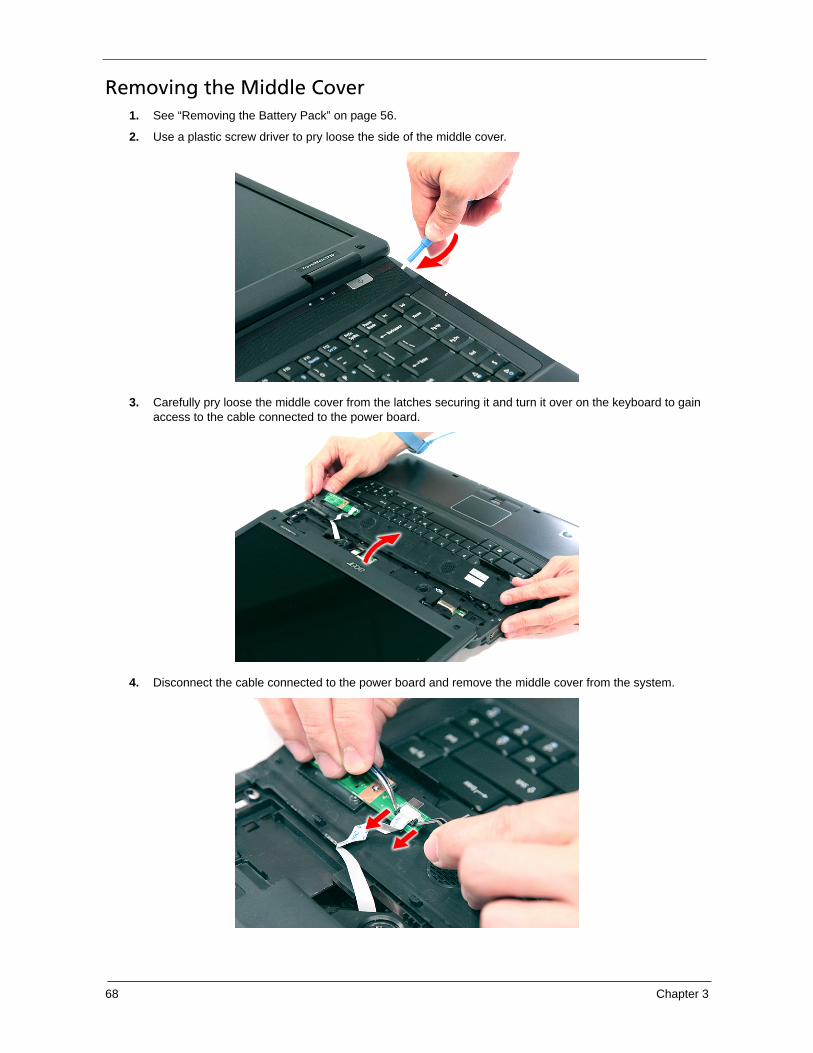
Removing the Middle Cover
1. See “Removing the Battery Pack” on page 56.
2. Use a plastic screw driver to pry loose the side of the middle cover.
3. Carefully pry loose the middle cover from the latches securing it and turn it over on the keyboard to gain access to the cable connected to the power board.
4. Disconnect the cable connected to the power board and remove the middle cover from the system.
Chapter 3 69
Removing the Power Board
1. See “Removing the Battery Pack” on page 56.
2. See “Removing the Middle Cover” on page 68.
70 Chapter 3
3. Remove the one screw (A) securing the power board to the middle cover.
4. Release the power board from the latches and remove it from the middle cover.
Step Size (Quantity) Color Torque
1 M2 x L3 (1) Silver 1.6 kgf-cm
Chapter 3 71
Removing the Keyboard
1. See “Removing the Battery Pack” on page 56.
2. See “Removing the Middle Cover” on page 68.
3. Remove the two screws (A) securing the keyboard.
4. Carefully pry loose the keyboard and turn it over on the touchpad area.
Step Size (Quantity) Color Torque
1~2 M2 x L3 (2) Silver 1.6 kgf-cm
72 Chapter 3
5. Disconnect the keyboard cable from the main board to remove the keyboard.
Removing the Heatsink Fan Module
1. See “Removing the Battery Pack” on page 56.
2. See “Removing the Lower Cover” on page 59.
3. Disconnect the heat sink fan connector from the main board.
Chapter 3 73
4. Remove the two screws (B) securing the heatsink fan module in place.
5. Carefully lift up the heatsink fan module.
Removing the CPU and VGA Heatsink Module
1. See “Removing the Battery Pack” on page 56.
2. See “Removing the Lower Cover” on page 59.
3. See “Removing the Heatsink Fan Module” on page 72.
Step Size (Quantity) Color Torque
1~2 M2 x L4 (2) Silver 1.6 kgf-cm
74 Chapter 3
4. Remove the four screws securing the VGA board heatsink module (Discrete Model only) and the five screw securing the CPU heatsink module.
5. Carefully remove the heatsink module from the system.
Removing the CPU
1. See “Removing the Battery Pack” on page 56.
2. See “Removing the Lower Cover” on page 59.
3. See “Removing the Heatsink Fan Module” on page 72.
4. See “Removing the CPU and VGA Heatsink Module” on page 73.
Chapter 3 75
5. Using a flat screwdriver, turn the CPU socket latch counter-clockwise to release the CPU.
6. Lift up carefully to remove the CPU.
NOTE: When installing the CPU, make sure to install the CPU with PIN 1 at the corner as shown.
Removing the VGA Board (Discrete Model only)
1. See “Removing the Battery Pack” on page 56.
2. See “Removing the Lower Cover” on page 59.
76 Chapter 3
3. See “Removing the Heatsink Fan Module” on page 72.
4. See “Removing the CPU and VGA Heatsink Module” on page 73.
5. Remove the two screws (B) securing the VGA board to the main board.
6. Remove the VGA board from the main board.
Removing the LCD Module
1. See “Removing the Battery Pack” on page 56.
2. See “Removing the SD dummy card” on page 57.
3. See “Removing the PC and ExpressCard dummy cards” on page 58.
4. See “Removing the Lower Cover” on page 59.
5. See “Removing the WLAN Board Modules” on page 61.
6. See “Removing the Middle Cover” on page 68.
7. See “Removing the Keyboard” on page 71.
Step Size (Quantity) Color Torque
1~2 M2 x L4 (2) Silver 1.6 kgf-cm
Chapter 3 77
8. Turn over the system and remove the two screws (B) from the bottom of the left and right hinges.
9. Carefully pull out the wireless antenna cables from the hole and release the cables from the latches.
10. Disconnect the LCD cable connector from the main board.
Step Size (Quantity) Color Torque
1~2 M2.5 x L6 (2) Black 3.0 kgf-cm
78 Chapter 3
11. Remove the two screws (D) from the left and right hinge of the LCD module.
12. Carefully remove the LCD module from the base unit.
NOTE: When connecting the cable back to the unit, please note that the cable should be routed well.
Separating the Upper Case from the Lower Case
1. See “Removing the Battery Pack” on page 56.
2. See “Removing the SD dummy card” on page 57.
3. See “Removing the PC and ExpressCard dummy cards” on page 58.
4. See “Removing the Lower Cover” on page 59.
5. See “Removing the DIMM” on page 60.
6. See “Removing the WLAN Board Modules” on page 61.
7. See “Removing the Hard Disk Drive Module” on page 63.
8. See “Removing the Optical Drive Module” on page 64.
9. See “Removing the Middle Cover” on page 68.
10. See “Removing the Keyboard” on page 71.
11. See “Removing the Heatsink Fan Module” on page 72.
12. See “Removing the CPU and VGA Heatsink Module” on page 73.
Step Size (Quantity) Color Torque
1~2 M2 x L8 (2) Black 4.0 kgf-cm
Chapter 3 79
13. See “Removing the CPU” on page 74.
14. See “Removing the VGA Board (Discrete Model only)” on page 75.
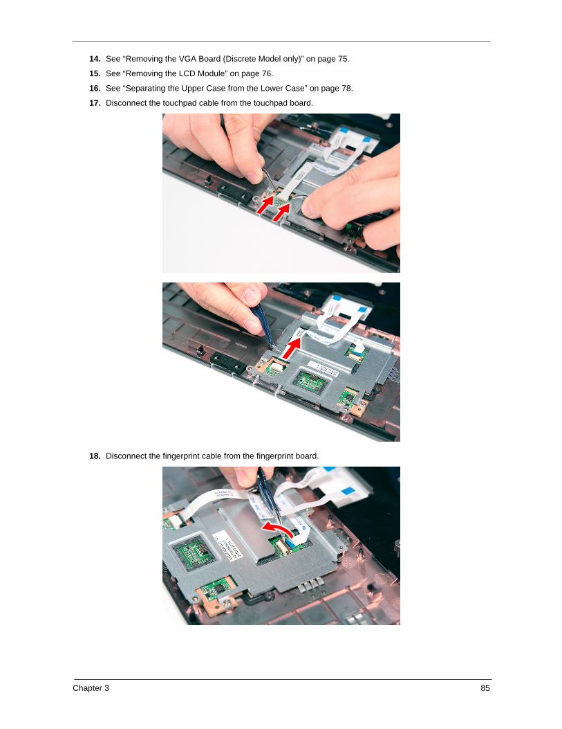
15. See “Removing the LCD Module” on page 76.
16. Disconnect the touchpad cable from the TPAD1 connector on the main board.
17. Disconnect the fingerprint cable from the FPCN1 connector on the main board.
80 Chapter 3
18. Disconnect the launch board cable from the SWITCHCN1 connector on the main board.
Chapter 3 81
19. Disconnect the speaker cable from the INTSPK1 connector on the main board.
20. Remove the fourteen screws (14 x C) from the bottom panel.
21. Turn the unit over and gently remove the upper case from the lower case.
Step Size (Quantity) Color Torque
1~14 M2.5 x L5 (14) Black 2.5 kgf-cm
82 Chapter 3
Removing the Speaker Module
1. See “Removing the Battery Pack” on page 56.
2. See “Removing the SD dummy card” on page 57.
3. See “Removing the PC and ExpressCard dummy cards” on page 58.
4. See “Removing the Lower Cover” on page 59.
5. See “Removing the DIMM” on page 60.
6. See “Removing the WLAN Board Modules” on page 61.
7. See “Removing the Hard Disk Drive Module” on page 63.
8. See “Removing the Optical Drive Module” on page 64.
9. See “Removing the Middle Cover” on page 68.
10. See “Removing the Keyboard” on page 71.
11. See “Removing the Heatsink Fan Module” on page 72.
12. See “Removing the CPU and VGA Heatsink Module” on page 73.
13. See “Removing the CPU” on page 74.
14. See “Removing the VGA Board (Discrete Model only)” on page 75.
15. See “Removing the LCD Module” on page 76.
16. See “Separating the Upper Case from the Lower Case” on page 78.
17. Remove the two screws (2 x H) securing the left and right speaker modules.
Step Size (Quantity) Color Torque
1~2 M2 x L3 (2) Silver 1.6 kgf-cm
Chapter 3 83
18. Remove the left and right speaker modules from the upper case.
Removing the Launch Board
1. See “Removing the Battery Pack” on page 56.
2. See “Removing the SD dummy card” on page 57.
3. See “Removing the PC and ExpressCard dummy cards” on page 58.
4. See “Removing the Lower Cover” on page 59.
5. See “Removing the DIMM” on page 60.
6. See “Removing the WLAN Board Modules” on page 61.
7. See “Removing the Hard Disk Drive Module” on page 63.
8. See “Removing the Optical Drive Module” on page 64.
9. See “Removing the Middle Cover” on page 68.
10. See “Removing the Keyboard” on page 71.
11. See “Removing the Heatsink Fan Module” on page 72.
12. See “Removing the CPU and VGA Heatsink Module” on page 73.
13. See “Removing the CPU” on page 74.
14. See “Removing the VGA Board (Discrete Model only)” on page 75.
15. See “Removing the LCD Module” on page 76.
16. See “Separating the Upper Case from the Lower Case” on page 78.
84 Chapter 3
17. Remove the one screw (1 x A) securing the launch board module.
18. Remove the launch board module from the upper case.
Removing the Fingerprint and Touchpad Module
1. See “Removing the Battery Pack” on page 56.
2. See “Removing the SD dummy card” on page 57.
3. See “Removing the PC and ExpressCard dummy cards” on page 58.
4. See “Removing the Lower Cover” on page 59.
5. See “Removing the DIMM” on page 60.
6. See “Removing the WLAN Board Modules” on page 61.
7. See “Removing the Hard Disk Drive Module” on page 63.
8. See “Removing the Optical Drive Module” on page 64.
9. See “Removing the Middle Cover” on page 68.
10. See “Removing the Keyboard” on page 71.
11. See “Removing the Heatsink Fan Module” on page 72.
12. See “Removing the CPU and VGA Heatsink Module” on page 73.
13. See “Removing the CPU” on page 74.
Step Size (Quantity) Color Torque
1 M2 x L3 (1) Silver 1.6 kgf-cm
Chapter 3 85
14. See “Removing the VGA Board (Discrete Model only)” on page 75.
15. See “Removing the LCD Module” on page 76.
16. See “Separating the Upper Case from the Lower Case” on page 78.
17. Disconnect the touchpad cable from the touchpad board.
18. Disconnect the fingerprint cable from the fingerprint board.
86 Chapter 3
19. Remove the three screws (2 x F, 1 x A) securing the bracket to the upper case.
20. Remove the touchpad bracket.
Step Size (Quantity) Color Torque
1~2 M2 x L3 (2) Silver 1.6 kgf-cm
3 M2 x L3 (2) Silver 1.6 kgf-cm
Chapter 3 87
21. Remove the fingerprint board module.
22. Carefully pry loose and remove the touch pad board.
WARNING:The touchpad board is glued to the upper case, only remove the touchpad board if it is defective.
Removing the Modem Board
1. See “Removing the Battery Pack” on page 56.
2. See “Removing the SD dummy card” on page 57.
88 Chapter 3
3. See “Removing the PC and ExpressCard dummy cards” on page 58.
4. See “Removing the Lower Cover” on page 59.
5. See “Removing the DIMM” on page 60.
6. See “Removing the WLAN Board Modules” on page 61.
7. See “Removing the Hard Disk Drive Module” on page 63.
8. See “Removing the Optical Drive Module” on page 64.
9. See “Removing the Middle Cover” on page 68.
10. See “Removing the Keyboard” on page 71.
11. See “Removing the Heatsink Fan Module” on page 72.
12. See “Removing the CPU and VGA Heatsink Module” on page 73.
13. See “Removing the CPU” on page 74.
14. See “Removing the VGA Board (Discrete Model only)” on page 75.
15. See “Removing the LCD Module” on page 76.
16. See “Separating the Upper Case from the Lower Case” on page 78.
17. Remove the two screws (B) securing the modem card.
18. Lift the modem board from the system.
Step Size (Quantity) Color Torque
1~2 M2 x L4 (2) Silver 1.6 kgf-cm
Chapter 3 89
19. Disconnect the cable from the modem board.
Removing the USB Board Module
1. See “Removing the Battery Pack” on page 56.
2. See “Removing the SD dummy card” on page 57.
3. See “Removing the PC and ExpressCard dummy cards” on page 58.
4. See “Removing the Lower Cover” on page 59.
5. See “Removing the DIMM” on page 60.
6. See “Removing the WLAN Board Modules” on page 61.
7. See “Removing the Hard Disk Drive Module” on page 63.
8. See “Removing the Optical Drive Module” on page 64.
9. See “Removing the Middle Cover” on page 68.
10. See “Removing the Keyboard” on page 71.
11. See “Removing the Heatsink Fan Module” on page 72.
12. See “Removing the CPU and VGA Heatsink Module” on page 73.
13. See “Removing the CPU” on page 74.
14. See “Removing the VGA Board (Discrete Model only)” on page 75.
15. See “Removing the LCD Module” on page 76.
16. See “Separating the Upper Case from the Lower Case” on page 78.
90 Chapter 3
17. Remove the one screw (B) securing the USB board to the lower case.
18. Lift the USB board and disconnect the cable from USBCN1 on the USB board.
Removing the Main Board
1. See “Removing the Battery Pack” on page 56.
2. See “Removing the SD dummy card” on page 57.
3. See “Removing the PC and ExpressCard dummy cards” on page 58.
4. See “Removing the Lower Cover” on page 59.
5. See “Removing the DIMM” on page 60.
6. See “Removing the WLAN Board Modules” on page 61.
7. See “Removing the Hard Disk Drive Module” on page 63.
8. See “Removing the Optical Drive Module” on page 64.
9. See “Removing the Middle Cover” on page 68.
10. See “Removing the Keyboard” on page 71.
11. See “Removing the Heatsink Fan Module” on page 72.
12. See “Removing the CPU and VGA Heatsink Module” on page 73.
13. See “Removing the CPU” on page 74.
Step Size (Quantity) Color Torque
1 M2 x L4 (1) Silver 1.6 kgf-cm
Chapter 3 91
14. See “Removing the VGA Board (Discrete Model only)” on page 75.
15. See “Removing the LCD Module” on page 76.
16. See “Separating the Upper Case from the Lower Case” on page 78.
17. See “Removing the Modem Board” on page 87.
18. See “Removing the USB Board Module” on page 89.
19. Disconnect the Bluetooth cable from BLUE1 on the main board.
20. Disconnect the DC cable from the DC1 connector on the main board.
92 Chapter 3
21. Remove the three screws (B) securing the main board in place.
22. Carefully remove the main board.
Step Size (Quantity) Color Torque
1~3 M2 x L4 (3) Silver 1.6 kgf-cm
Chapter 3 93
LCD Module Disassembly Process
LCD Module Disassembly Flowchart
Screw List
Item Screw Color Part No.
B M2 x L4 Silver 86.9A552.4R0
C M2.5 x L5 Black 86.00E33.736
G M2.5 x L5 Black 86.00F87.735
LCD MODULE
LCD BEZEL
Cx4
LCD ASSEMBLY
LEFT LCDBRACKET
Bx2
RIGHT LCDBRACKET
Bx2
LCD FPCCABLE LCD BACK PANEL
ANTENNAS
LCD MODULE DISASSEMBLY
Gx6, B2
VGACAMERA
94 Chapter 3
Removing the LCD Bezel
1. See “Removing the Battery Pack” on page 56.
2. See “Removing the SD dummy card” on page 57.
3. See “Removing the PC and ExpressCard dummy cards” on page 58.
4. See “Removing the Lower Cover” on page 59.
5. See “Removing the WLAN Board Modules” on page 61.
6. See “Removing the Middle Cover” on page 68.
7. See “Removing the Keyboard” on page 71.
8. See “Removing the LCD Module” on page 76.
9. Remove the four screw covers from the LCD bezel.
10. Remove the four screws (C) on the LCD module as shown.
Step Size (Quantity) Color Torque
1~4 M2.5 x L6 (4) Black 3.0 kgf-cm
Chapter 3 95
11. Carefully pry open the LCD bezel and place the bezel on top of the LCD panel.
12. Disconnect the microphone cable and remove the bezel from the LCD panel.
96 Chapter 3
Removing the LCD module with the Brackets
1. See “Removing the Battery Pack” on page 56.
2. See “Removing the SD dummy card” on page 57.
3. See “Removing the PC and ExpressCard dummy cards” on page 58.
4. See “Removing the Lower Cover” on page 59.
5. See “Removing the WLAN Board Modules” on page 61.
6. See “Removing the Middle Cover” on page 68.
7. See “Removing the Keyboard” on page 71.
8. See “Removing the LCD Module” on page 76.
9. See “Removing the LCD Bezel” on page 94.
10. Disconnect the cable from the web camera.
11. Remove the eight screws (6 x G, 2 x B) securing the LCD module.
Step Size (Quantity) Color Torque
1~6 M2.5 x L6 (6) Black 2.5 kgf-cm
7~8 M2 x L4 (2) Silver 1.6 kgf-cm
Chapter 3 97
12. Remove the LCD with the brackets from the back cover.
Removing the FPC Cable
1. See “Removing the Battery Pack” on page 56.
2. See “Removing the SD dummy card” on page 57.
3. See “Removing the PC and ExpressCard dummy cards” on page 58.
4. See “Removing the Lower Cover” on page 59.
5. See “Removing the WLAN Board Modules” on page 61.
6. See “Removing the Middle Cover” on page 68.
7. See “Removing the Keyboard” on page 71.
8. See “Removing the LCD Module” on page 76.
9. See “Removing the LCD Bezel” on page 94.
10. See “Removing the LCD module with the Brackets” on page 96.
11. Disconnect the cables from the inverter board.
98 Chapter 3
12. Detach any adhesive tapes and any cable that is glued to the LCD panel.
Chapter 3 99
13. Disconnect the FPC cable from the LCD panel.
Removing the LCD Brackets
1. See “Removing the Battery Pack” on page 56.
2. See “Removing the Lower Cover” on page 59.
3. See “Removing the WLAN Board Modules” on page 61.
4. See “Removing the Keyboard” on page 71.
5. See “Removing the Middle Cover” on page 68.
6. See “Removing the LCD Module” on page 76.
7. See “Removing the LCD Bezel” on page 94.
8. See “Removing the LCD module with the Brackets” on page 96.
9. See “Removing the FPC Cable” on page 97.
100 Chapter 3
10. Remove the four screws (4 x B) securing the left and right LCD brackets to remove the brackets.
Removing the Antennas
1. See “Removing the Battery Pack” on page 56.
2. See “Removing the Lower Cover” on page 59.
3. See “Removing the WLAN Board Modules” on page 61.
4. See “Removing the Keyboard” on page 71.
5. See “Removing the Middle Cover” on page 68.
6. See “Removing the LCD Module” on page 76.
7. See “Removing the LCD Bezel” on page 94.
8. See “Removing the LCD module with the Brackets” on page 96.
9. Release the antenna cables from the aluminium tapes.
Step Size (Quantity) Color Torque
1~4 M2 x L4 (4) Silver 1.6 kgf-cm
Chapter 3 101
10. Remove the tapes together holding the antenna in place.
NOTE: There is no need to remove the antenna unless you really need to replace it.
Removing the Web Camera
1. See “Removing the Battery Pack” on page 56.
2. See “Removing the Lower Cover” on page 59.
3. See “Removing the WLAN Board Modules” on page 61.
4. See “Removing the Keyboard” on page 71.
5. See “Removing the Middle Cover” on page 68.
6. See “Removing the LCD Module” on page 76.
7. See “Removing the LCD Bezel” on page 94.
8. See “Removing the LCD module with the Brackets” on page 96.
102 Chapter 3
9. Remove the Web camera from the back cover.
Chapter 4 103
Use the following procedure as a guide for computer problems.
NOTE: The diagnostic tests are intended to test only Acer products. Non-Acer products, prototype cards, or modified options can give false errors and invalid system responses.
1. Obtain the failing symptoms in as much detail as possible.
2. Verify the symptoms by attempting to re-create the failure by running the diagnostic test or by repeating the same operation.
3. Use the following table with the verified symptom to determine which page to go to.
Symptoms (Verified) Go To
Power failure. (The power indicator does not go on or stay on.)
“Power System Check” on page 105.
POST does not complete. No beep or error codes are indicated.
“Power-On Self-Test (POST) Error Message” on page 108“Undetermined Problems” on page 122
POST detects an error and displayed messages on screen.
“Error Message List” on page 109
Other symptoms (i.e. LCD display problems or others).
“Power-On Self-Test (POST) Error Message” on page 108
Symptoms cannot be re-created (intermittent problems).
Use the customer-reported symptoms and go to “Power-On Self-Test (POST) Error Message” on page 108
“Intermittent Problems” on page 121
“Undetermined Problems” on page 122
Troubleshooting
Chapter 4
104 Chapter 4
System Check Procedures
External Diskette Drive Check
Do the following to isolate the problem to a controller, driver, or diskette. A write-enabled, diagnostic diskette is required.
NOTE: Make sure that the diskette does not have more than one label attached to it. Multiple labels can cause damage to the drive or cause the drive to fail.
Do the following to select the test device.
1. Boot from the diagnostics diskette and start the diagnostics program.
2. See if FDD Test is passed as the program runs to FDD Test.
3. Follow the instructions in the message window.
If an error occurs with the internal diskette drive, reconnect the diskette connector on the system board.
If the error still remains:
1. Reconnect the external diskette drive/DVD-ROM module.
2. Replace the external diskette drive/CD-ROM module.
3. Replace the main board.
External CD-ROM Drive Check
Do the following to isolate the problem to a controller, drive, or CD-ROM. Make sure that the CD-ROM does not have any label attached to it. The label can cause damage to the drive or can cause the drive to fail.
Do the following to select the test device:
1. Boot from the diagnostics diskette and start the diagnostics program.
2. See if CD-ROM Test is passed when the program runs to CD-ROM Test.
3. Follow the instructions in the message window.
If an error occurs, reconnect the connector on the System board. If the error still remains:
1. Reconnect the external diskette drive/CD-ROM module.
2. Replace the external diskette drive/CD-ROM module.
3. Replace the main board.
Keyboard or Auxiliary Input Device Check
Remove the external keyboard if the internal keyboard is to be tested.
If the internal keyboard does not work or an unexpected character appears, make sure that the flexible cable extending from the keyboard is correctly seated in the connector on the system board.
If the keyboard cable connection is correct, run the Keyboard Test.
If the tests detect a keyboard problem, do the following one at a time to correct the problem. Do not replace a non-defective FRU:
1. Reconnect the keyboard cables.
2. Replace the keyboard.
3. Replace the main board.
The following auxiliary input devices are supported by this computer:
� Numeric keypad
Chapter 4 105
� External keyboard
If any of these devices do not work, reconnect the cable connector and repeat the failing operation.
Memory check
Memory errors might stop system operations, show error messages on the screen, or hang the system.
1. Boot from the diagnostics diskette and start the diagnostic program (please refer to main board.
2. Go to the diagnostic memory in the test items.
3. Press F2 in the test items.
4. Follow the instructions in the message window.
NOTE: Make sure that the DIMM is fully installed into the connector. A loose connection can cause an error.
Power System Check
To verify the symptom of the problem, power on the computer using each of the following power sources:
1. Remove the battery pack.
2. Connect the power adapter and check that power is supplied.
3. Disconnect the power adapter and install the charged battery pack; then check that power is supplied by the battery pack.
If you suspect a power problem, see the appropriate power supply check in the following list:
� “Check the Power Adapter” on page 106
� “Check the Battery Pack” on page 107
106 Chapter 4
Check the Power Adapter
Unplug the power adapter cable from the computer and measure the output voltage at the plug of the power adapter cable. See the following figure
1. If the voltage is not correct, replace the power adapter.
2. If the voltage is within the range, do the following:
� Replace the System board.
� If the problem is not corrected, see “Undetermined Problems” on page 122.
� If the voltage is not correct, go to the next step.
NOTE: An audible noise from the power adapter does not always indicate a defect.
3. If the power-on indicator does not light up, check the power cord of the power adapter for correct continuity and installation.
4. If the operational charge does not work, see “Check the Battery Pack” on page 107.
Pin 1: +19 to +20.5VPin 2: 0V, Ground
Chapter 4 107
Check the Battery Pack
To check the battery pack, do the following:
From Software:
1. Check out the Power Management in control Panel
2. In Power Meter, confirm that if the parameters shown in the screen for Current Power Source and Total Battery Power Remaining are correct.
3. Repeat the steps 1 and 2, for both battery and adapter.
4. This helps you identify first the problem is on recharging or discharging.
From Hardware:
1. Power off the computer.
2. Remove the battery pack and measure the voltage between battery terminals 1(+) and 6(ground).
3. If the voltage is still less than 7.5 Vdc after recharging, replace the battery.
To check the battery charge operation, use a discharged battery pack or a battery pack that has less than 50% of the total power remaining when installed in the computer.
If the battery status indicator does not light up, remove the battery pack and let it return to room temperature. Re-install the battery pack.
If the charge indicator still does not light up, replace the battery pack. If the charge indicator still does not light up, replace the DC/DC charger board.
Touchpad Check
If the touchpad doesn’t work, do the following actions one at a time to correct the problem. Do not replace a non-defective FRU:
1. Reconnect the touchpad cables.
2. Replace the touchpad.
3. Replace the system board.
After you use the touchpad, the pointer drifts on the screen for a short time. This self-acting pointer movement can occur when a slight, steady pressure is applied to the touchpad pointer. This symptom is not a hardware problem. No service actions are necessary if the pointer movement stops in a short period of time.
108 Chapter 4
Power-On Self-Test (POST) Error Message The POST error message index lists the error message and their possible causes. The most likely cause is listed first.
NOTE: Perform the FRU replacement or actions in the sequence shown in FRU/Action column, if the FRU replacement does not solve the problem, put the original part back in the computer. Do not replace a non-defective FRU.
This index can also help you determine the next possible FRU to be replaced when servicing a computer.
If the symptom is not listed, see “Undetermined Problems” on page 122.
The following lists the error messages that the BIOS displays on the screen and the error symptoms classified by function.
NOTE: Most of the error messages occur during POST. Some of them display information about a hardware device, e.g., the amount of memory installed. Others may indicate a problem with a device, such as the way it has been configured.
NOTE: If the system fails after you make changes in the BIOS Setup Utility menus, reset the computer, enter Setup and install Setup defaults or correct the error.
Chapter 4 109
Index of Error Messages
Error Code List
Error Codes Error Messages
006 Equipment Configuration Error
Causes:
1. CPU BIOS Update Code Mismatch
2. IDE Primary Channel Master Drive Error(THe causes will be shown before “Equipment Configuration Error”)
010 Memory Error at xxxx:xxxx:xxxxh (R:xxxxh, W:xxxxh)
070 Real Time Clock Error
071 CMOS Battery Bad
072 CMOS Checksum Error
110 System disabled.Incorrect password is specified.
<No error code> Battery critical LOWIn this situation BIOS will issue 4 short beeps then shut down system, no message will show.
<No error code> Thermal critical High
In this situation BIOS will shut down system, not show message.
Error Message List
Error Messages FRU/Action in Sequence
Failure Fixed Disk Reconnect hard disk drive connector.“Load Default Settings” in BIOS Setup Utility.
Hard disk drive
System board
Stuck Key see “Keyboard or Auxiliary Input Device Check” on page 104.
Keyboard error see “Keyboard or Auxiliary Input Device Check” on page 104.
Keyboard Controller Failed see “Keyboard or Auxiliary Input Device Check” on page 104.
98h 1-2 Search for option ROMs. One long, two short beeps on checksum failure.
99h Check for SMART drive (optional)
9Ah Shadow option ROMs
9Ch Set up Power Management
9Dh Initialize security engine (optional)
9Eh Enable hardware interrupts
9Fh Determine number of ATA and SCSI drives
A0h Set time of day
A2h Check key lock
A4h Initialize Typematic rate
A8h Erase F2 prompt
AAh Scan for F2 key stroke
ACh Enter SETUP
AEh Clear Boot flag
B0h Check for errors
B2h POST done- prepare to boot operating system
B4h 1 One short beep before boot
B5h Terminate QuietBoot (optional)
B6h Check password (optional)
Code Beeps POST Routine Description
Chapter 4 115
B9h Prepare Boot
BAh Initialize DMI parameters
BBh Initialize PnP Option ROMs
BCh Clear parity checkers
BDh Display MultiBoot menu
BEh Clear screen (optional)
BFh Check virus and backup reminders
C0h Try to boot with INT 19
C1h Initialize POST Error Manager (PEM)
C2h Initialize error logging
C3h Initialize error display function
C4h Initialize system error handler
C5h PnPnd dual CMOS (optional)
C6h Initialize notebook docking (optional)
C7h Initialize notebook docking late
C8h Force check (optional)
C9h Extended checksum (optional)
D2h Unknown interrupt
Code Beeps
E0h Initialize the chipset
E1h Initialize the bridge
E2h Initialize the CPU
E3h Initialize the system timer
E4h Initialize system I/O
E5h Check force recovery boot
E6h Checksum BIOS ROM
E7h Go to BIOS
E8h Set Huge Segment
E9h Initialize Multi Processor
EAh Initialize OEM special code
EBh Initialize PIC and DMA
ECh Initialize Memory type
EDh Initialize Memory size
EEh Shadow Boot Block
EFh System memory test
F0h Initialize interrupt vectors
F1h Initialize Run Time Clock
F2h Initialize video
F3h Initialize System Management Mode
F4h 1 Output one beep before boot
Code Beeps POST Routine Description
116 Chapter 4
F5h Boot to Mini DOS
F6h Clear Huge Segment
F7h Boot to Full DOS
Code Beeps
Chapter 4 117
Index of Symptom-to-FRU Error Message
LCD-Related Symptoms
Symptom / Error Action in Sequence
LCD backlight doesn't work
LCD is too dark
LCD brightness cannot be adjusted
LCD contrast cannot be adjusted
Enter BIOS Utility to execute “Load Setup Default Settings”, then reboot system.Reconnect the LCD connectors.
Keyboard (if contrast and brightness function key doesn't work).
LCD inverter ID
LCD cable
LCD inverterLCD
System board
Unreadable LCD screen Missing pels in characters
Abnormal screen
Wrong color displayed
Reconnect the LCD connectorLCD inverter ID
LCD cable
LCD inverter
LCD
System board
LCD has extra horizontal or vertical lines displayed.
LCD inverter ID
LCD inverter
LCD cableLCD
System board
Indicator-Related Symptoms
Symptom / Error Action in Sequence
Indicator incorrectly remains off or on, but system runs correctly
Reconnect the inverter board
Inverter boardSystem board
Power-Related Symptoms
Symptom / Error Action in Sequence
Power shuts down during operation Power source (battery pack and power adapter). See “Power System Check” on page 105.
Battery pack
Power adapterHard drive & battery connection board
System board
The system doesn’t power-on. Power source (battery pack and power adapter). See “Power System Check” on page 105.
Battery packPower adapter
Hard drive & battery connection board
System board
118 Chapter 4
The system doesn’t power-off. Power source (battery pack and power adapter). See “Power System Check” on page 105.
Hold and press the power switch for more than 4 seconds.
System board
Battery can’t be charged See “Check the Battery Pack” on page 107.
Battery pack
System board
PCMCIA-Related Symptoms
Symptom / Error Action in Sequence
System cannot detect the PC Card (PCMCIA)
PCMCIA slot assembly
System board
PCMCIA slot pin is damaged. PCMCIA slot assembly
Memory-Related Symptoms
Symptom / Error Action in Sequence
Memory count (size) appears different from actual size.
Enter BIOS Setup Utility to execute “Load Default Settings, then reboot system.
DIMM
System board
Speaker-Related Symptoms
Symptom / Error Action in Sequence
In Windows, multimedia programs, no sound comes from the computer.
Audio driver
Speaker
System board
Internal speakers make noise or emit no sound.
Speaker
System board
Power Management-Related Symptoms
Symptom / Error Action in Sequence
The system will not enter hibernation See “Save to Disk (S4)” on page 35.
Keyboard (if control is from the keyboard)
Hard disk driveSystem board
The system doesn't enter hibernation mode and four short beeps every minute.
Press Fn+o and see if the computer enters hibernation mode.
TouchpadKeyboard
Hard disk connection board
Hard disk drive
System board
The system doesn’t enter standby mode after closing the LCD
See “Save to Disk (S4)” on page 35.
LCD cover switch
System board
Power-Related Symptoms
Symptom / Error Action in Sequence
Chapter 4 119
The system doesn't resume from hibernation mode.
See “Save to Disk (S4)” on page 35.
Hard disk connection board
Hard disk driveSystem board
The system doesn't resume from standby mode after opening the LCD.
See “Save to Disk (S4)” on page 35.
LCD cover switchSystem board
Battery fuel gauge in Windows doesn’t go higher than 90%.
Remove battery pack and let it cool for 2 hours.
Refresh battery (continue use battery until power off, then charge battery).
Battery packSystem board
System hangs intermittently. Reconnect hard disk/CD-ROM drives.
Hard disk connection boardSystem board
Peripheral-Related Symptoms
Symptom / Error Action in Sequence
System configuration does not match the installed devices.
Enter BIOS Setup Utility to execute “Load Default Settings”, then reboot system.
Reconnect hard disk/CD-ROM/diskette drives.
External display does not work correctly. Press Fn+F5, LCD/CRT/Both display switching
System board
USB does not work correctly System board
Print problems. Ensure the “Parallel Port” in the “Onboard Devices Configuration” of BIOS Setup Utility is set to Enabled.
Onboard Devices Configuration
Run printer self-test.Printer driver
Printer cable
Printer
System Board
Serial or parallel port device problems. Ensure the “Serial Port” in the Devices Configuration” of BIOS Setup Utility is set to Enabled.
Device driver
Device cable
DeviceSystem board
Keyboard/Touchpad-Related Symptoms
Symptom / Error Action in Sequence
Keyboard (one or more keys) does not work.
Reconnect the keyboard cable.
Keyboard
System board
Power Management-Related Symptoms
Symptom / Error Action in Sequence
120 Chapter 4
NOTE: If you cannot find a symptom or an error in this list and the problem remains, see “Undetermined Problems” on page 122.
Touchpad does not work. Reconnect touchpad cable.
Touchpad board
System board
Modem-Related Symptoms
Symptom / Error Action in Sequence
Internal modem does not work correctly. Modem phone port
modem combo board
System board
Keyboard/Touchpad-Related Symptoms
Symptom / Error Action in Sequence
Chapter 4 121
Intermittent ProblemsIntermittent system hang problems can be caused by a variety of reasons that have nothing to do with a hardware defect, such as: cosmic radiation, electrostatic discharge, or software errors. FRU replacement should be considered only when a recurring problem exists.
When analyzing an intermittent problem, do the following:
1. Run the advanced diagnostic test for the system board in loop mode at least 10 times.
2. If no error is detected, do not replace any FRU.
3. If any error is detected, replace the FRU. Rerun the test to verify that there are no more errors.
122 Chapter 4
Undetermined ProblemsThe diagnostic problems does not identify which adapter or device failed, which installed devices are incorrect, whether a short circuit is suspected, or whether the system is inoperative.
Follow these procedures to isolate the failing FRU (do not isolate non-defective FRU).
NOTE: Verify that all attached devices are supported by the computer.
NOTE: Verify that the power supply being used at the time of the failure is operating correctly. (See “Power System Check” on page 105.):
1. Power-off the computer.
2. Visually check them for damage. If any problems are found, replace the FRU.
3. Remove or disconnect all of the following devices:
� Non-Acer devices
� Printer, mouse, and other external devices
� Battery pack
� Hard disk drive
� DIMM
� CD-ROM/Diskette drive Module
� PC Cards
4. Power-on the computer.
5. Determine if the problem has changed.
6. If the problem does not recur, reconnect the removed devices one at a time until you find the failing FRU.
7. If the problem remains, replace the following FRU one at a time. Do not replace a non-defective FRU:
� System board
� LCD assembly
Chapter 5 123
Top and Bottom View
Jumper and Connector Locations
Chapter 5
124 Chapter 5
Chapter 5 125
Clearing Password Check and BIOS RecoveryThis section provide you the standard operating procedures of clearing password and BIOS recovery for TravelMate 5730 Series. TravelMate 5730 Series provide one Hardware Open Gap on main board for clearing password check, and one Hotkey for enabling BIOS Recovery.
Clearing Password Check
Hardware Open Gap Description
HW Gap position on M/B space:
Gap name in TravelMate 5730 Series is G77
Steps for Clearing BIOS Password Check
If users set BIOS Password (Supervisor Password and/or User Password) for a security reason, BIOS will ask the password during systems POST or when systems enter to BIOS Setup menu. However, once it is necessary to bypass the password check, users need to short the HW Gap to clear the password by the following steps:
• Power Off a system, and remove HDD, AC and Battery from the machine.
• Open the back cover of the machine, and find out the HW Gap on M/B as picture.
• Use an electric conductivity tool to short the two points of the HW Gap.
• Plug in AC, keep the short condition on the HW Gap, and press Power Button to power on the system till BIOS POST finish. Then remove the tool from the HW Gap.
• Restart system. Press F2 key to enter BIOS Setup menu.
• If there is no Password request, BIOS Password is cleared. Otherwise, please follow the steps and try again.
NOTE: The steps are only for clearing BIOS Password (Supervisor Password and User Password).
Hardware Default Setting Operation Description
Gap Open (Normal) Short (Clearing Password Check)
G77
126 Chapter 5
BIOS Recovery by Crisis Disk
BIOS Recovery Boot Block:
BIOS Recovery Boot Block is a special block of BIOS. It is used to boot up the system with minimum BIOS initialization. Users can enable this feature to restore the BIOS firmware to a successful one once the previous BIOS flashing process failed.
BIOS Recovery Hotkey:
The system provides a function hotkey: Fn+Esc, for enable BIOS Recovery process when system is powered on during BIOS POST. To use this function, it is strongly recommended to have the AC adapter and Battery present. If this function is enabled, the system will force the BIOS to enter a special BIOS block, called Boot Block.
Steps for BIOS Recovery by Crisis Disk:
Before doing this, one Crisis Disk should be prepared ready in hand. The Crisis Disk could be made by executing the Crisis Disk program in another system with Windows XP OS.
Follow the steps below:
1. Power Off system.
2. Insert the Crisis Disk to a USB floppy drive which is attached to the BIOS flash failed machine.
3. In the power-off state, press Fn+Esc and hold them and then press Power Button. The system should be powered on with Crisis BIOS Recovery process.
4. BIOS Boot Block starts to restore the BIOS code from the Crisis floppy disk to BIOS ROM on the failed machine.
5. If the Crisis flashing process is finished, the system will restart.
If the Crisis Recovery process is finished, the system should be powered on with successful and workable BIOS. Then a person can update the latest version BIOS for this machine by regular BIOS flashing process.
Chapter 6 127
This chapter gives you the FRU (Field Replaceable Unit) listing in global configurations of 5930/5930Z/5730Z Series. Refer to this chapter whenever ordering for parts to repair or for RMA (Return Merchandise Authorization).
Please note that WHEN ORDERING FRU PARTS, you should check the most up-to-date information available on your regional web or channel. For whatever reasons a part number change is made, it will not be noted on the printed Service Guide. For ACER AUTHORIZED SERVICE PROVIDERS, your Acer office may have a DIFFERENT part number code from those given in the FRU list of this printed Service Guide. You MUST use the local FRU list provided by your regional Acer office to order FRU parts for repair and service of customer machines.
NOTE: To scrap or to return the defective parts, you should follow the local government ordinance or regulations on how to dispose it properly, or follow the rules set by your regional Acer office on how to return it.
FRU (Field Replaceable Unit) List
Chapter 6
128 Chapter 6
TravelMate 5730 Series Exploded Diagram
Chapter 6 129
TravelMate 5730 Series FRU List
Category No. Part Name and Description Acer Part No.
This computer’s compatibility is tested and verified by Acer’s internal testing department. All of its system
functions are tested under Windows® XP Home, Windows® XP Pro environment.
Refer to the following lists for components, adapter cards, and peripherals which have passed these tests. Regarding configuration, combination and test procedures, please refer to the TravelMate 5730 series Compatibility Test Report released by the Acer Mobile System Testing Department.
This section describes online technical support services available to help you repair your Acer Systems.
If you are a distributor, dealer, ASP or TPM, please refer your technical queries to your local Acer branch office. Acer Branch Offices and Regional Business Units may access our website. However some information sources will require a user i.d. and password. These can be obtained directly from Acer CSD Taiwan.
Acer's Website offers you convenient and valuable support resources whenever you need them.
In the Technical Information section you can download information on all of Acer's Notebook, Desktop and Server models including:
� Service guides for all models
� User's manuals
� Training materials
� Bios updates
� Software utilities
� Spare parts lists
� TABs (Technical Announcement Bulletin)
For these purposes, we have included an Acrobat File to facilitate the problem-free downloading of our technical material.
Also contained on this website are:
� Detailed information on Acer's International Traveller’s Warranty (ITW)
� Returned material authorization procedures
� An overview of all the support services we offer, accompanied by a list of telephone, fax and email contacts for all your technical queries.
We are always looking for ways to optimize and improve our services, so if you have any suggestions or comments, please do not hesitate to communicate these to us.