18
SERVICE MANUAL MODEL BLE3ATW Vol. 2.0 From To Serial Numbers K6 104551 101141 103681 101141 U.S.A. Canada EU Au. N.Z

SERVICE MANUAL
MODEL BLE3ATW
Vol. 2.0
From
To
Serial Numbers
K6 104551 101141103681 101141
U.S.A. Canada EU Au. N.Z

1.Construction of Covers
1
4.6
2.0
1
72.8
5.3
4.8
8.6
1.8
12.5
55.7
11.5
11.2
10.6
Heigh
t of r
ight n
eedle
Heigh
t of p
ress
er fo
ot
Distan
ce of
chain
loop
ertip
from
right
side o
f cha
in rig
ht ne
edle
(BLE
5, BL
E8W
)
Distan
ce of
chain
loop
ertip
from
right
side o
f cha
in rig
ht ne
edle
(BLC
S(3))
For B
LE5,B
LE8W
For B
LE3A
TW
For B
LCS(
3)Fo
r BLE
1SX,
DX,
AT
Heigh
t of
feed d
og
Distance of lower looper tipfrom center of lower looper shaft
Distance of chain looper tipfrom center of chain looper shaft(BLE5, BLE8W)
Distance of Upper looper tip From right side of right needle
Distance of lower looper tipfrom right side of right needle(SX, DX, AT, ATW)
Distance of lower looper tipfrom right side of right needle(BLE5, BLE8W)
New Adjusting Gauge

2. Ad
justm
ent o
f Nee
dle,Lo
wer lo
oper,
Upp
er lo
oper,
Chain
lopp
er &
Pre
sser
foot
R55.7+0.1
Heigh
t of p
ress
er fo
otHe
ight o
f nee
dle
Need
le pla
te
11.2+0.1
Uppe
r loop
er ad
justm
ent
8.6
Adjus
tmen
t of lo
wer lo
oper
and u
pper
loop
er
Lowe
r loop
er ad
justm
ent
Max.
8.5
Need
le gu
ard
adjus
tmen
t0.8
+0.3
+0.1
0
00Need
le 2.0
Fron
t nee
dle gu
ardBack
need
legu
ard
5.3+0
.1
Righ
t Nee
dle
Righ
t Nee
dle
Org
anH
Ax1
SP
#14
/CR
(#90
)
Org
anH
Ax1
SP
#14
/CR
(#90
)
Org
anH
Ax1
SP
#14
/CR
(#90
)Ri
ght N
eedle
2
4.5+0.2
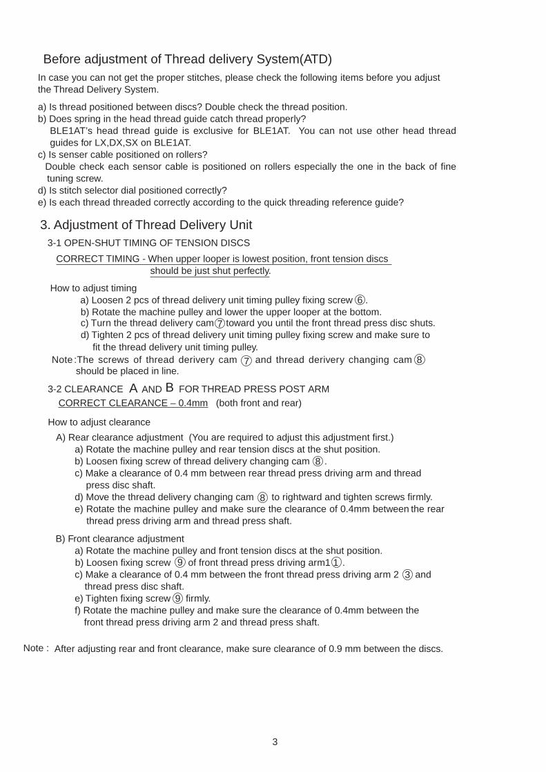
Before adjustment of Thread delivery System(ATD)In case you can not get the proper stitches, please check the following items before you adjust the Thread Delivery System.
a) Is thread positioned between discs? Double check the thread position.b) Does spring in the head thread guide catch thread properly?
BLE1AT’s head thread guide is exclusive for BLE1AT. You can not use other head threadguides for LX,DX,SX on BLE1AT.
c) Is senser cable positioned on rollers?Double check each sensor cable is positioned on rollers especially the one in the back of finetuning screw.
d) Is stitch selector dial positioned correctly?e) Is each thread threaded correctly according to the quick threading reference guide?
3. Adjustment of Thread Delivery Unit 3-1 OPEN-SHUT TIMING OF TENSION DISCS
CORRECT TIMING - When upper looper is lowest position, front tension discs should be just shut perfectly.
How to adjust timing a) Loosen 2 pcs of thread delivery unit timing pulley fixing screw . b) Rotate the machine pulley and lower the upper looper at the bottom. c) Turn the thread delivery cam toward you until the front thread press disc shuts.
fit the thread delivery unit timing pulley.Note :The screws of thread derivery cam and thread derivery changing cam
should be placed in line.
3-2 CLEARANCE A AND B FOR THREAD PRESS POST ARM CORRECT CLEARANCE – 0.4mm (both front and rear)
How to adjust clearanceA) Rear clearance adjustment (You are required to adjust this adjustment first.)
a) Rotate the machine pulley and rear tension discs at the shut position.b) Loosen fixing screw of thread delivery changing cam .c) Make a clearance of 0.4 mm between rear thread press driving arm and thread
press disc shaft.d) Move the thread delivery changing cam to rightward and tighten screws firmly.e) Rotate the machine pulley and make sure the clearance of 0.4mm between the rear
thread press driving arm and thread press shaft.
B) Front clearance adjustmenta) Rotate the machine pulley and front tension discs at the shut position.b) Loosen fixing screw of front thread press driving arm1 .c) Make a clearance of 0.4 mm between the front thread press driving arm 2 and
thread press disc shaft.e) Tighten fixing screw firmly.f) Rotate the machine pulley and make sure the clearance of 0.4mm between the
front thread press driving arm 2 and thread press shaft.
Note : After adjusting rear and front clearance, make sure clearance of 0.9 mm between the discs.
3
d) Tighten 2 pcs of thread delivery unit timing pulley fixing screw and make sure to
6
7
7 8
8
8
9
9
13

Rear clearance adjustment A
Front clearance adjustment B
Shut position
Shut position
0.4
0.4
Openposition
Openposition
4
5
6
7
8
0.9mm 0.4mm
4
3
1 2
9
3
1 2
9
8

3-3 HOW TO REPLACE THE TIMING BELT OF THREAD DELIVERY UNIT (see P6) a) Loosen the presser foot joint link fixing screw A( 24 upper screw).b) Loosen the thread delivery unit fixing screw .c) Remove 2 pcs of the thread delivery unit fixing screw . d) Push the thread delivery unit downward and remove the timing belt of thread delivery unit .
Then, remove the motor belt and you can replace the timing belt of thread delivery unit. e) Return 2 pcs of the thread delivery unit fixing screw .
You are required to adjust the clearance at 1mm between handle and the timing pulley. (E)f) Tighten the screw and screw A( 27 upper screw).g) Adjustment of timing see P.3, 1-1
3-4 HOW TO REPLACE THE THREAD DELIVERY UNIT (see P.6)a) Remove the selector knob link fixing screw & spacer . b) Remove 3 pcs of sensor cable B, C & D. c) Remove 3 pcs of thread delivery unit fixing screw & . d) Remove the thread delivery unit timing belt and you can remove the thread delivery unit from
the machine.e) Replace the thread delivery unit and assemble each part in the order of d) - c) - b) - a).f) Make sure that the 3 pcs of sensor cable are exactly in the roller.g) After you replace the thread delivery unit, you are required to adjust and check following items;
1) Adjustment of timing (see P.3, 1-1) 2) Check the stitches (see P.9, 2).
3-5 HOW TO REPLACE THE SPRINGS OF THREAD DELIVERY UNIT (see P.6) a) Stitch connecting arm plate spring Hook the spring both sideb) Looper thread pulling plate spring Hook the spring both sidec) Thread pulling movable spring
Remove the edge of hook of thread pulling movable spring , loosen the fixing screw and replacethe spring and space at the same time.
d) Disc press spring (both front and rear)1)Remove 5 pcs. of E-ring of the thread press disc shaft and pull out the press disc shaft leftward.
Becareful not to splash the spring. 2) After you replace the spring , insert the thread press disc shaft slowly from the right side. 3) Pushing the thread press disc shaft from the right side, rotate the machine pulley until the
thread press driving arm reaches the far left. 4) Replace 5 pcs. of E-ring.5) Make a clearance of 0.4mm between the thread press driving arm and thread press disc
shaft . (see P3, 1-2)
2
5
23
3
1 16
2
30 29
2 316
1415
99
1011
12
12

6
15 5 4
12
3
16
1011
14
1
229
30
23
24
2527
28
26
9
13
2122
1918
17
20
6 78
A

3-6 REPLACEMENT OF SENSOR CABLE (see P.8) Needle thread and looper thread sensor cable consists of 113 pcs of fine stainless wire and itspulling strength is 13kg (3 lb.). Therefore, it is almost unnecessary to replacethe sensor cable. In case you replace the cable, refer the followings;
There are 3 types of sensor cable and each cable is different length.* Fabric thickness sensor cable 3 Mono wire* Needle thread sensor cable 2 about 320mm (12 inch.) * Looper thread sensor cable 1 about 498mm (20 inch.)
a) Replacement of fabric thickness sensor cable 31) Remove the cable 2) Hook the cable both side. 3) Check the stitches (see P.9, 4).
b) Replacement of needle thread sensor cable 21) Move the stitch joint arm plate B to the right and remove the needle thread sensor cable2. 2) Replace the cable and make sure that the cable is in each 4 grooves of guide roller. 3) Check the stitches (see P.9, 4).
c) Replacement of looper thread sensor cable 11) Move the looper thread pulling plate C to the left and remove the looper thread sensor
cable1. 2) Replace the cable and make sure that the cable is in each 5 grooves of guide roller. 3) Check the stitches (see P.9, 4).
3
7

45
13
6
1615
32
1
5
7
1817
5
20
19 23
5
21
24
22
109
45
12 48
11
14
8

4. ADJUSTMENT OF STITCHESfabric : cotton 1-layer thread : 100% polyester spun thread (maxi-lock or metrosene thread) needle : SCHMETZ HAX1SP #11/CR machine: 1-needle (right), 3-thread sewing width : 5.0mm (max) length : 3.0mm D.F. : N stitch selector : B
4-1 ADJUSTMENT OF NEEDLE THREAD SENSOR CABLE
The needle thread sensor cable effects the timing of both needle thread andlooper threads. You are required to adjust this cable first.
NOTE: The needle thread sensor cable adjusting screw works; Turn clockwise and both needle & looper threads become loose. Turn counter-clockwise and both needle & looper threads become tight.
a) Line up the looper thread fine-tuning screw at the standard position.b) Sew 1-layer of cotton with 1-needle (right) 3-thread as shown in the above
and adjust only the needle thread in the stitch not to have a puckering. Disregard the looper threads in the stitch at this stage.
c) Then, adjust the looper thread sensor cable (4-2).
4-2 ADJUSTMENT OF LOOPER THREAD SENSOR CABLE Before the adjustment of looper thread sensor cable, adjust the needle thread sensor cable first (4-1).
NOTE: The looper thread sensor cable adjusting screw works; * Turn clockwise and looper threads become loose. * Turn counter-clockwise and looper threads become tight.
a) Line up the looper thread fine-tuning screw at the standard position.b) Sew 1-layer of cotton with 1-needle (right) 3-thread as shown in the previous page and turn the
screw until you get the ideal stitch which looper threads are not loose and fabric is not curled. c) After adjustment of looper thread sensor cable, the timing of needle thread
might be changed. Therefore, check the needle thread sensor cable again (see 4-1).
9

Needle thread sensor cable
Looper thread sensor cable
Looper thread sensor cableadjusting screw
Needle thread sensor cable adjusting screw
Standard Position
Fine Tuning screw
10
Turn Clockwise Become LooseTurn Counter-clockwise Become Tight

5. ADJUSTMENT OF NEEDLE THREADER (see P12)Before you adjust the needle threader, you are required to exchange the new needles of SCHMETZ HAX1SP #14CR as the bent needles or different needles cause the incorrect timing of needle threader. Also, you are required to make sure that needles are positioned in the needleclamp holder correctly.
5-1 REPLACEMENT OF NEEDLE THREADERa) Remove the needle threader hook fixing screw and replace the hook . b) Insert the hook until the end of needle threader selector plate and tighten the needle
threader hook fixing screw . c) Change the needle threader select plate right and left, and make sure if the needle threader
works both for right and left needles.
5-2 ADJUSTMENT OF HIGH AND LOW DIRECTION FOR NEEDLE THREADERa) Lock the machine.b) Make sure that the needle threader hook is positioned until the end of needle threader
select plate . c) Bend the place A on needle threader holder and adjust the direction of high and low for the
needle threader. d) Change the needle threader select plate right and left, and make sure if the needle threader
works both for right and left needles.
5-3 ADJUSTMENT OF RIGHT AND LEFT DIRECTION FOR NEEDLE THREADERa) Lock the machine.b) Loosen the screw and move the needle threader holder right and left until the needle
threader works properly. c) Tighten the screw . d) Change the needle threader select plate right and left, and make sure if the needle threader
works both for right and left needles.
3-4 ADJUSTMENT OF NEEDLE THREADER SAFETY PLATEa) Align the green marks on the pulley.b) Loosen the screw and adjust the position of washer (14 upper washer) in order to make
the needle threader safety plate lowered smoothly when the needle threader lever is lowered.c) Tighten the screw . d) Rotate the machine pulley and make sure that the needle threader lever is not lowered
when the needles are not in the highest position.
11
22 2020 28
28
28
28
28
22
20
23
24
24
23
19
19 A32
32

12
31
29
30
28
25
23
27
26
24
222120
33
323534
36
6
12
8
4 3
2
1
10
119
1314
1516
17
19
5
18
76
A

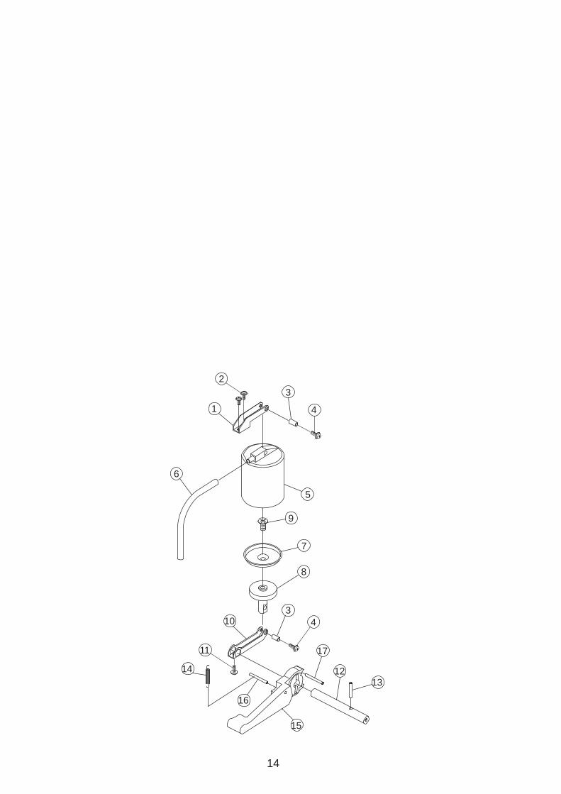
6. Checking threading steel pipe joint (see p .14)
a) Set the machine for looper threading.b) Move the lock button release lever slightly to the right.c) Check the connecting point whether the looper threading pipe joint and threading
steel pipe is fitted each other properly.
7. Checking pump7-1 Checking deflate from pump
Holding the pump tube 6 , push down the pump lever 15 and check if air is deflated frompump or not.
7-2 Replacement of Piston Cap
a) Bring the pump lever to the lowest position and fix it with Scotch tape or something like that.b) Remove bace plate. c) Remove piston driving arm fixing screw 11 (SM3005ZU). d) Remove piston driving arm from piston driving shaft.
(It will be easy to remove the arm from the shaft, if you push the shaft to the rightwarddirection.)
e) Remove piston assembly from cylinder (It will be easy to remove piston assenbly from cylinder, when the needle is in the lowestposition.)
f) Replace piston cap.g) Greace piston cap a little bit.(MOLYKOTE EM-50L) h) Return piston assembly to cylinder.i) Fit piston driving arm to piston driving shaft properly and tighten fixing screw 11 (SM3005IK) firmly.
(It will be easy to fit the arm to the shaft, if you push the shaft to the leftward direction.) j) Check and confirm whether the pump works properly or not.k) fix bace plate.
6
13
3
5
4
3
9
8
15
1213
4
17
2
1
6
10
14
11
16
7
14

5.53.0
Fixing screwof Knife holder
Fixing screwof knife drivingshaft
Knife drivingshaft
0.5mm
8. CUTTING WIDTH ADJUSTMENT
a) Cut 1 layar cotton fabric and make a cutting width 3.7 0.1mm between the eye of needle and the edge of fabric.
b) Cutting width adjustment Loosen fixing screws of knife holder, and knife driving shaft.
Turn Knife driving shaft crockwise or counter-clockwise.
Make sure cutting width.
c) Rotate the stitch width dial to min. 3.0/5.5mm, distance between lower knife and needle plate is more than 0.5mm.
Machine SettingsNeedle : Right Needle(O2)Thread : No UseStitch Width : MStitch Length: 2.5Differencial feed : NFabric : Cotton broad 1 layer
3.7 0.1mm
+
+
15

180
Pin
Chaining tongueholder pin
Chaining tongueholder
Chaining tongueholder pin
Adjusting chainingtongue
Adjusting chainingtongue
Screw
A B
9. How to replace adjusting chaining tongue
a) Move the pin to leftward.
b) Remove chaining tongue holder set with adjusting chaining tongue.
c)Loosen screw of adjusting chaining tongue and remove holder pin. Replace the adjusting chaining tongue with new one.
d)Make pararell between "A" (flat side of chaining holder pin) and "B" (top surface of adjusting chaining tongue), and tighten the screw temporary.
e)Replace chaining tongue holder set, and make sure that top of adjusting chaining tongue is parallel with needle plate.
f)Remove chaining holder set again, tighten the screw firmly.
g)Replace chaining holder set.
Chaining tongue holder set
16

10. TROUBLE SHOOTING
10-1 NEEDLE THREADS ARE UNBALANCED ;* Is the serger threaded correctly? See Quick Reference Guide* Are the threads snapped in the head guide? See Instruction Book P.12* Is the stitch selector positioned correctly? See Quick Reference Guide* Is the looper thread fine-tuning screw positioned correctly?
See Instruction Book P.13* Are the threads recommended high quality? See Instruction Book P.7 * Is the needle thread sensor cable positioned correctly? See P7, 3-6* Is the needle thread sensor cable adjusted correctly? See P9, 4
10-2 LOOPER THREADS ARE UNBALANCED ;* Is the serger threaded correctly? See Quick Reference Guide* Are the threads snapped in the head guide? See Instruction Book P.12* Is the stitch selector positioned correctly? See Quick Reference Guide* Is the looper thread fine-tuning screw positioned correctly?
See Instruction Book P.13* Are the threads recommended high quality? See Instruction Book P.7
* Is the serger threaded correctly? See Quick Reference Guide* Are the threads snapped in the head guide? See Instruction Book P.12* Is the stitch selector positioned correctly? See Quick Reference Guide* Is the looper thread fine-tuning screw positioned correctly?
See Instruction Book P.13* Are the threads recommended high quality? See Instruction Book P.7
* Is the looper thread sensor cable positioned correctly? See P7, 3-6* Is the looper thread sensor cable adjusted correctly? See P9, 4
10-3 THREAD BREAKS ;
10-4 NEEDLE THREADER WORKS IMPROPERLY ; * Are the needles inserted until the end of clamp holder? See P11, 5* Is the height of each needle correct? See P 2 * Is the adjustment of needle threader correct? See P11, 5
10-5 JET AIR THREADER DOES NOT WORK*Is air deflated from pump? See P13, 7 *Are pipes connected properly? See P13, 6*Are there any lints or thread in pipes?
10-6 WAVE STITCH IS NOT FORMED;*Is the machine threaded correctly? See Quick Reference Guide *Is the machine set for 3-Thread Wave stitching? See Instruction Book P.33*Is the Wave Selector shows "W" ? See Instruction Book P.33
17
*For Rolled Wave Edging, is the stitch length dial set for "ROLLED HEM" ? See Instruction Book P.35*Is the Stitch Selector set correctly? Set the Stitch Selector at "B" for 3-Thread Wave Stitch or "C" for 3-Thread Rolled Wave Stitch. See Instruction Book P.34,35


