166
Service Manual Bulletin 1336 FORCE Adjustable Frequency AC Drive Series B, C, D B300 – B600 C300 – C650 Allen-Bradley efesotomasyon.com - Allen Bradley,Rockwell,plc,servo,drive

ServiceManual
Bulletin 1336 FORCEAdjustable FrequencyAC DriveSeries B, C, DB300 – B600 C300 – C650
Allen-Bradley
efesotomasyon.com - Allen Bradley,Rockwell,plc,servo,drive

Because of the variety of uses for the products described in thispublication, those responsible for the application and use of thiscontrol equipment must satisfy themselves that all necessary stepshave been taken to assure that each application and use meets allperformance and safety requirements, including any applicable laws,regulations, codes and standards.
The illustrations, charts, sample programs and layout examplesshown in this guide are intended solely for purposes of example.Since there are many variables and requirements associated with anyparticular installation, Allen-Bradley does not assume responsibilityor liability (to include intellectual property liability) for actual usebased upon the examples shown in this publication.
Allen-Bradley publication SGI-1.1, Safety Guidelines for theApplication, Installation, and Maintenance of Solid-State Control(available from your local Allen-Bradley office), describes someimportant differences between solid-state equipment andelectromechanical devices that should be taken into considerationwhen applying products such as those described in this publication.
Reproduction of the contents of this copyrighted publication, inwhole or in part, without written permission of Allen-BradleyCompany, Inc., is prohibited.
Throughout this manual we use notes to make you aware of safetyconsiderations:
!ATTENTION: Identifies information about practicesor circumstances that can lead to personal injury ordeath, property damage or economic loss.
Attention statements help you to:
• identify a hazard
• avoid the hazard
• recognize the consequences
Important: Identifies information that is critical for successfulapplication and understanding of the product.
ControlNet is a trademark; PLC is a registered trademark of Allen-Bradley Company, Inc.
Important UserInformation
efesotomasyon.com - Allen Bradley,Rockwell,plc,servo,drive

Summary of Changes
Publication 1336 FORCE-6.15 – August, 1999
Summary of Changes
The information below summarizes the changes to thecompany-wide templates since the last release.
The derating tables in the Preface have been removed. Refer to the1336 FORCE User Manual.
Updated Information
efesotomasyon.com - Allen Bradley,Rockwell,plc,servo,drive

Summary of Changes
Publication 1336 FORCE-6.15 – August, 1999
This Page Intentionally Left Blank
efesotomasyon.com - Allen Bradley,Rockwell,plc,servo,drive

Publication 1336 FORCE-6.15 – August, 1999
Manual Objective P–1. . . . . . . . . . . . . . . . . . . . . . . . . . . . . . . . . . . . . Who Should UseThis Manual P–1. . . . . . . . . . . . . . . . . . . . . . . . . . . . Safety Precautions P–1. . . . . . . . . . . . . . . . . . . . . . . . . . . . . . . . . . . . Electrostatic DischargePrecautions P–2. . . . . . . . . . . . . . . . . . . . . . . . 1336 FORCE Product Identification P–3. . . . . . . . . . . . . . . . . . . . . . . .
Drive Nameplate Location P–3. . . . . . . . . . . . . . . . . . . . . . . . . . . . Software Compatibility P–4. . . . . . . . . . . . . . . . . . . . . . . . . . . . . . .
Drive and OptionIdentification P–5. . . . . . . . . . . . . . . . . . . . . . . . . . . . 1336 FORCE Drive Catalog Numbers P–5. . . . . . . . . . . . . . . . . . . . Drive Rating Qualifications P–7. . . . . . . . . . . . . . . . . . . . . . . . . . . . Enclosure Type P–7. . . . . . . . . . . . . . . . . . . . . . . . . . . . . . . . . . . .
Conventions P–8. . . . . . . . . . . . . . . . . . . . . . . . . . . . . . . . . . . . . . . . Auxiliary Input P–8. . . . . . . . . . . . . . . . . . . . . . . . . . . . . . . . . . . . . Auxiliary Interlock P–8. . . . . . . . . . . . . . . . . . . . . . . . . . . . . . . . . . Bit P–8. . . . . . . . . . . . . . . . . . . . . . . . . . . . . . . . . . . . . . . . . . . . . Check P–8. . . . . . . . . . . . . . . . . . . . . . . . . . . . . . . . . . . . . . . . . . . Connector P–8. . . . . . . . . . . . . . . . . . . . . . . . . . . . . . . . . . . . . . . . Default P–9. . . . . . . . . . . . . . . . . . . . . . . . . . . . . . . . . . . . . . . . . . Enable Input P–9. . . . . . . . . . . . . . . . . . . . . . . . . . . . . . . . . . . . . . False P–9. . . . . . . . . . . . . . . . . . . . . . . . . . . . . . . . . . . . . . . . . . . Jumper P–9. . . . . . . . . . . . . . . . . . . . . . . . . . . . . . . . . . . . . . . . . . Control Interface Board P–9. . . . . . . . . . . . . . . . . . . . . . . . . . . . . . Parameter P–9. . . . . . . . . . . . . . . . . . . . . . . . . . . . . . . . . . . . . . . . Press P–9. . . . . . . . . . . . . . . . . . . . . . . . . . . . . . . . . . . . . . . . . . . True P–10. . . . . . . . . . . . . . . . . . . . . . . . . . . . . . . . . . . . . . . . . . . .
Related Publications P–10. . . . . . . . . . . . . . . . . . . . . . . . . . . . . . . . . .
Chapter 1
Chapter Objectives 1–1. . . . . . . . . . . . . . . . . . . . . . . . . . . . . . . . . . . Chapter Overview 1–1. . . . . . . . . . . . . . . . . . . . . . . . . . . . . . . . . . . . Control Interface Option 1–3. . . . . . . . . . . . . . . . . . . . . . . . . . . . . . . .
Control Interface L-Option Board Jumpers 1–3. . . . . . . . . . . . . . . . . Available Inputs 1–4. . . . . . . . . . . . . . . . . . . . . . . . . . . . . . . . . . . .
Standard Adapter Local Programming 1–4. . . . . . . . . . . . . . . . . . . . . . Adapters and Communication Ports 1–9. . . . . . . . . . . . . . . . . . . . . . .
Human Interface Module 1–9. . . . . . . . . . . . . . . . . . . . . . . . . . . . . HIM Removal 1–12. . . . . . . . . . . . . . . . . . . . . . . . . . . . . . . . . . . . . HIM Operation 1–12. . . . . . . . . . . . . . . . . . . . . . . . . . . . . . . . . . . . .
Graphic Programming Terminal 1–13. . . . . . . . . . . . . . . . . . . . . . . . . . . GPT Description 1–13. . . . . . . . . . . . . . . . . . . . . . . . . . . . . . . . . . .
Drive Tools 1–14. . . . . . . . . . . . . . . . . . . . . . . . . . . . . . . . . . . . . . . . . Control Firmware Function 1–14. . . . . . . . . . . . . . . . . . . . . . . . . . . . . .
Table of Contents
Preface
Control Logic Wiring andAdapters
efesotomasyon.com - Allen Bradley,Rockwell,plc,servo,drive

Table of Contentsii
Publication 1336 FORCE-6.15 – August, 1999
Chapter 2
Chapter Objectives 2–1. . . . . . . . . . . . . . . . . . . . . . . . . . . . . . . . . . . Disassembly and Access Overview 2–1. . . . . . . . . . . . . . . . . . . . . . . . Electrostatic Discharge Precautions 2–2. . . . . . . . . . . . . . . . . . . . . . .
Tools 2–2. . . . . . . . . . . . . . . . . . . . . . . . . . . . . . . . . . . . . . . . . . . Fastener Torque Specifications 2–3. . . . . . . . . . . . . . . . . . . . . . . . . . .
Torque Sequence 2–3. . . . . . . . . . . . . . . . . . . . . . . . . . . . . . . . . . Torque Specifications 2–4. . . . . . . . . . . . . . . . . . . . . . . . . . . . . . . .
Disassembly and Access Procedures 2–6. . . . . . . . . . . . . . . . . . . . . . Opening the Drive Enclosure 2–6. . . . . . . . . . . . . . . . . . . . . . . . . .
Opening 2–7. . . . . . . . . . . . . . . . . . . . . . . . . . . . . . . . . . . . . . . Closing the Drive Enclosure 2–8. . . . . . . . . . . . . . . . . . . . . . . . .
Removing the Control Interface L-Option Board Mod –L4, –L5, or –L6 2–9. . . . . . . . . . . . . . . . . . . . . . . . . . . . . . . . .
Removal 2–9. . . . . . . . . . . . . . . . . . . . . . . . . . . . . . . . . . . . . . . Installation 2–10. . . . . . . . . . . . . . . . . . . . . . . . . . . . . . . . . . . . . .
Removing the Main Control Board 2–11. . . . . . . . . . . . . . . . . . . . . . . Removal 2–11. . . . . . . . . . . . . . . . . . . . . . . . . . . . . . . . . . . . . . . Installation 2–13. . . . . . . . . . . . . . . . . . . . . . . . . . . . . . . . . . . . . .
Removing the Standard Adapter Board 2–13. . . . . . . . . . . . . . . . . . . Removal 2–14. . . . . . . . . . . . . . . . . . . . . . . . . . . . . . . . . . . . . . .
Installation 2–14. . . . . . . . . . . . . . . . . . . . . . . . . . . . . . . . . . . . . . . Removing the PLC Comm Adapter Board 2–15. . . . . . . . . . . . . . . . .
Removal 2–16. . . . . . . . . . . . . . . . . . . . . . . . . . . . . . . . . . . . . . . Installation 2–16. . . . . . . . . . . . . . . . . . . . . . . . . . . . . . . . . . . . . .
Removing the Control Board/Adapter Mounting Plate 2–17. . . . . . . . . Removal 2–18. . . . . . . . . . . . . . . . . . . . . . . . . . . . . . . . . . . . . . . Installation 2–19. . . . . . . . . . . . . . . . . . . . . . . . . . . . . . . . . . . . . .
Removing the Gate Driver Board 2–20. . . . . . . . . . . . . . . . . . . . . . . .
Chapter 3
Chapter Objectives 3–1. . . . . . . . . . . . . . . . . . . . . . . . . . . . . . . . . . . Component Test Overview 3–1. . . . . . . . . . . . . . . . . . . . . . . . . . . . . . Electrostatic Discharge Precautions 3–2. . . . . . . . . . . . . . . . . . . . . . .
Tools 3–2. . . . . . . . . . . . . . . . . . . . . . . . . . . . . . . . . . . . . . . . . . . Test 1 Testing the Gate Driver Board 3–3. . . . . . . . . . . . . . . . . . . . . . Test 2 Testing the Precharge Board 3–7. . . . . . . . . . . . . . . . . . . . . . . . Test 3 Testing the Power Modules 3–9. . . . . . . . . . . . . . . . . . . . . . . . . Test 4 Testing the Bus Capacitors 3–12. . . . . . . . . . . . . . . . . . . . . . . . . Test 5 Testing the SCRs 3–15. . . . . . . . . . . . . . . . . . . . . . . . . . . . . . . .
Disassembly and AccessProcedures
Component Test Procedures
efesotomasyon.com - Allen Bradley,Rockwell,plc,servo,drive

Table of Contents iii
Publication 1336 FORCE-6.15 – August, 1999
Chapter 4
Chapter Objective 4–1. . . . . . . . . . . . . . . . . . . . . . . . . . . . . . . . . . . . Part Replacement Overview 4–1. . . . . . . . . . . . . . . . . . . . . . . . . . . . . Safety Precautions 4–1. . . . . . . . . . . . . . . . . . . . . . . . . . . . . . . . . . . . Electrostatic Discharge Precautions 4–2. . . . . . . . . . . . . . . . . . . . . . . Major Component Replacement 4–3. . . . . . . . . . . . . . . . . . . . . . . . . . Detailed Product Identification 4–3. . . . . . . . . . . . . . . . . . . . . . . . . . . .
Bus Capacitor Bank 4–5. . . . . . . . . . . . . . . . . . . . . . . . . . . . . . . . . Removal 4–6. . . . . . . . . . . . . . . . . . . . . . . . . . . . . . . . . . . . . . . Installation 4–7. . . . . . . . . . . . . . . . . . . . . . . . . . . . . . . . . . . . . .
Thermistor 4–8. . . . . . . . . . . . . . . . . . . . . . . . . . . . . . . . . . . . . . . Removal 4–9. . . . . . . . . . . . . . . . . . . . . . . . . . . . . . . . . . . . . . . Installation 4–10. . . . . . . . . . . . . . . . . . . . . . . . . . . . . . . . . . . . . .
Power Modules 4–11. . . . . . . . . . . . . . . . . . . . . . . . . . . . . . . . . . . . Removal 4–12. . . . . . . . . . . . . . . . . . . . . . . . . . . . . . . . . . . . . . . Installation 4–13. . . . . . . . . . . . . . . . . . . . . . . . . . . . . . . . . . . . . .
Power Module Snubber Resistor 4–14. . . . . . . . . . . . . . . . . . . . . . . . Removal 4–15. . . . . . . . . . . . . . . . . . . . . . . . . . . . . . . . . . . . . . . Installation 4–16. . . . . . . . . . . . . . . . . . . . . . . . . . . . . . . . . . . . . .
SCRs 4–16. . . . . . . . . . . . . . . . . . . . . . . . . . . . . . . . . . . . . . . . . . . Removal 4–17. . . . . . . . . . . . . . . . . . . . . . . . . . . . . . . . . . . . . . . Installation 4–19. . . . . . . . . . . . . . . . . . . . . . . . . . . . . . . . . . . . . .
Fan and Transformer Assembly 4–20. . . . . . . . . . . . . . . . . . . . . . . . Removal 4–21. . . . . . . . . . . . . . . . . . . . . . . . . . . . . . . . . . . . . . . Installation 4–22. . . . . . . . . . . . . . . . . . . . . . . . . . . . . . . . . . . . . .
DC Bus Inductor 4–23. . . . . . . . . . . . . . . . . . . . . . . . . . . . . . . . . . . Removal 4–24. . . . . . . . . . . . . . . . . . . . . . . . . . . . . . . . . . . . . . . Installation 4–25. . . . . . . . . . . . . . . . . . . . . . . . . . . . . . . . . . . . . .
Ground Sense CT 4–26. . . . . . . . . . . . . . . . . . . . . . . . . . . . . . . . . . Removal 4–26. . . . . . . . . . . . . . . . . . . . . . . . . . . . . . . . . . . . . . . Installation 4–27. . . . . . . . . . . . . . . . . . . . . . . . . . . . . . . . . . . . . .
Bus Fuses 4–28. . . . . . . . . . . . . . . . . . . . . . . . . . . . . . . . . . . . . . . . Removal 4–28. . . . . . . . . . . . . . . . . . . . . . . . . . . . . . . . . . . . . . . Installation 4–29. . . . . . . . . . . . . . . . . . . . . . . . . . . . . . . . . . . . . .
LEMs 4–30. . . . . . . . . . . . . . . . . . . . . . . . . . . . . . . . . . . . . . . . . . . Removal 4–30. . . . . . . . . . . . . . . . . . . . . . . . . . . . . . . . . . . . . . . Installation 4–31. . . . . . . . . . . . . . . . . . . . . . . . . . . . . . . . . . . . . .
MOV Surge Suppressor 4–32. . . . . . . . . . . . . . . . . . . . . . . . . . . . . . Removal 4–32. . . . . . . . . . . . . . . . . . . . . . . . . . . . . . . . . . . . . . . Installation 4–34. . . . . . . . . . . . . . . . . . . . . . . . . . . . . . . . . . . . . .
Chapter Objective 4–1. . . . . . . . . . . . . . . . . . . . . . . . . . . . . . . . . . . . Part Replacement Overview 4–1. . . . . . . . . . . . . . . . . . . . . . . . . . . . . Safety Precautions 4–1. . . . . . . . . . . . . . . . . . . . . . . . . . . . . . . . . . . . Electrostatic Discharge Precautions 4–2. . . . . . . . . . . . . . . . . . . . . . . Major Component Replacement 4–3. . . . . . . . . . . . . . . . . . . . . . . . . .
Part ReplacementProcedures
efesotomasyon.com - Allen Bradley,Rockwell,plc,servo,drive

Table of Contentsiv
Publication 1336 FORCE-6.15 – August, 1999
Detailed Product Identification 4–3. . . . . . . . . . . . . . . . . . . . . . . . . . . . Bus Capacitor Bank 4–5. . . . . . . . . . . . . . . . . . . . . . . . . . . . . . . . . Thermistor 4–8. . . . . . . . . . . . . . . . . . . . . . . . . . . . . . . . . . . . . . . Power Modules 4–11. . . . . . . . . . . . . . . . . . . . . . . . . . . . . . . . . . . . Power Module Snubber Resistor 4–14. . . . . . . . . . . . . . . . . . . . . . . . SCRs 4–16. . . . . . . . . . . . . . . . . . . . . . . . . . . . . . . . . . . . . . . . . . . Fan and Transformer Assembly 4–20. . . . . . . . . . . . . . . . . . . . . . . . DC Bus Inductor 4–23. . . . . . . . . . . . . . . . . . . . . . . . . . . . . . . . . . . Ground Sense CT 4–26. . . . . . . . . . . . . . . . . . . . . . . . . . . . . . . . . . Bus Fuses 4–28. . . . . . . . . . . . . . . . . . . . . . . . . . . . . . . . . . . . . . . . LEMs 4–30. . . . . . . . . . . . . . . . . . . . . . . . . . . . . . . . . . . . . . . . . . . MOV Surge Suppressor 4–32. . . . . . . . . . . . . . . . . . . . . . . . . . . . . .
Chapter 5
Chapter Objectives 5–1. . . . . . . . . . . . . . . . . . . . . . . . . . . . . . . . . . . Ordering Replacement Parts 5–1. . . . . . . . . . . . . . . . . . . . . . . . . . . . . Replacement Parts Listing 5–2. . . . . . . . . . . . . . . . . . . . . . . . . . . . . .
Chapter 6
Replacement Parts List
Schematics — 300 – 600 HP1336 FORCE Drives
Glossary
Index
efesotomasyon.com - Allen Bradley,Rockwell,plc,servo,drive

Preface
P–1
Preface
The information in this manual is designed to help repair anAllen-Bradley Bulletin 1336 FORCE Adjustable Frequency ACDrive with ratings B300 – B600, C300 – C600, and BX250.
This manual is intended for qualified service personnel responsiblefor repairing the 1336 FORCE Adjustable Frequency AC Drive. Youshould:
• Read this entire manual before performing maintenance or repairsto drives.
• Have previous experience with, and basic understanding of,electrical terminology, procedures, required equipment,equipment protection procedures and methods, and safetyprecautions.
This manual describes equipment and disassembly procedures. Youbegin with general illustrations and end with greater detailconcerning replacement parts and part locations on the drives. Laterchapters may refer you back to earlier chapters for information onbasic equipment and steps necessary to perform detailed diagnosticsand part replacement.
!ATTENTION: Some printed circuit boards and drivecomponents may contain hazardous voltage levels.Remove and lock out power before you disconnect orreconnect wires, and before you remove or replacefuses and circuit boards. Verify bus voltage bymeasuring the voltage between the Negative CapacitorBus and both ends of all three 350 amp fuses. An openfuse does not show voltage across both ends of thefuse. Failure to measure voltage at both ends of thefuses may result in death or serious injury. Refer toFigure 2.5. Do not attempt to service the drive until thebus voltage has discharged to zero volts.
Manual Objective
Who Should UseThis Manual
Safety Precautions
efesotomasyon.com - Allen Bradley,Rockwell,plc,servo,drive

PrefaceP–2
Publication 1336 FORCE-6.15 – August, 1999
!ATTENTION: Potentially fatal voltages may resultfrom improper usage of oscilloscope and other testequipment. The oscilloscope chassis may be at apotentially fatal voltage if not properly grounded. If anoscilloscope is used to measure high voltagewaveforms, use only a dual channel oscilloscope in thedifferential mode with X 100 probes. It isrecommended that the oscilloscope be used in the Aminus B Quasi-differential mode with the oscilloscopechassis correctly grounded to an earth ground.
!ATTENTION: Only personnel familiar with the1336 FORCE Adjustable Frequency AC Drive andassociated machinery should plan or implement theinstallation, start-up and subsequent maintenance of thesystem. Failure to comply may result in personal injuryand/or equipment damage.
!ATTENTION: This assembly contains parts andsub-assemblies that are sensitive to electrostaticdischarge. Static control precautions are required whenservicing this assembly. Component damage may resultif you ignore electrostatic discharge control procedures.If you are not familiar with static control procedures,reference Allen-Bradley Publication 8000-4.5.2,Guarding Against Electrostatic Damage, or any otherapplicable ESD protection handbook.
Electrostatic discharge generated by static electricity can damage thecomplimentary metallic oxide semiconductor devices on variousdrive boards. It is recommended that you perform these proceduresto guard against this type of damage when circuit boards areremoved or installed:
• Wear a wrist-type grounding strap that is grounded to the drivechassis.
• Attach the wrist strap before removing the new circuit board fromthe conductive packet.
• Remove boards from the drive and immediately insert them intotheir conductive packets.
Electrostatic DischargePrecautions
efesotomasyon.com - Allen Bradley,Rockwell,plc,servo,drive

Preface P–3
Publication 1336 FORCE-6.15 – August, 1999
Drive Nameplate Location
The drive nameplate is located on the face of the Main ControlBoard mounting plate. The drive nameplate contains the drive’scatalog number and other important drive information. Reference thecatalog number when ordering replacement parts.
Figure P.1Drive Nameplate Location
AB0541A
Nameplate located onbottom of PC Board
Mounting Frame
1336 FORCEProduct Identification
efesotomasyon.com - Allen Bradley,Rockwell,plc,servo,drive
PrefaceP–4
Publication 1336 FORCE-6.15 – August, 1999
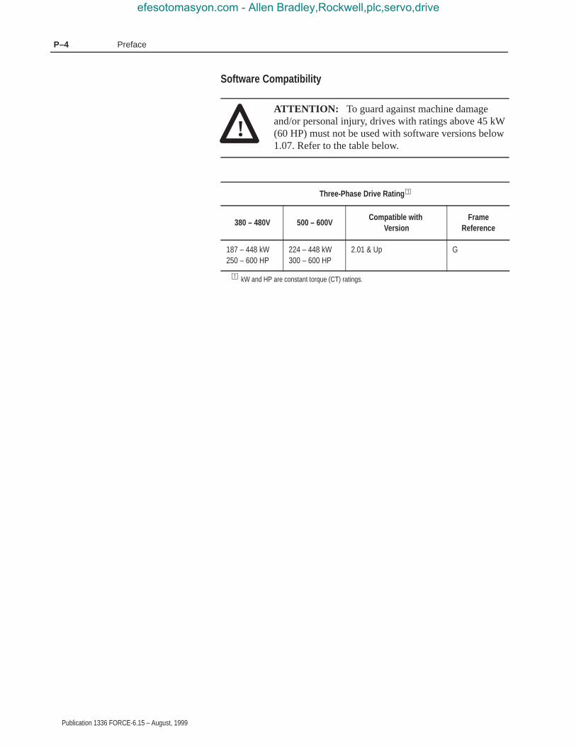
Software Compatibility
!ATTENTION: To guard against machine damageand/or personal injury, drives with ratings above 45 kW(60 HP) must not be used with software versions below1.07. Refer to the table below.
Three-Phase Drive Rating �
380 – 480V 500 – 600VCompatible with
VersionFrame
Reference
187 – 448 kW250 – 600 HP
224 – 448 kW300 – 600 HP
2.01 & Up G
� kW and HP are constant torque (CT) ratings.
efesotomasyon.com - Allen Bradley,Rockwell,plc,servo,drive

Preface P–5
Publication 1336 FORCE-6.15 – August, 1999
The following is an explanation of the catalog numbering system for1336 FORCE Adjustable Frequency AC Drives and options. Thecatalog number is coded to identify the drive power rating and can befound on the drive shipping carton and nameplate.
1336 FORCE Drive Catalog Numbers
Table P.A
1336T – B007 – AA – CM – GT2EN – GM1
BULLETINNO.
DRIVE RATING ENCLOSURE STYLE(Must be specified)
COMMON MODECHOKE
ADAPTER(Must be specified)
OPTIONS
380 – 480V AC Input, Constant Torque Drive
Drive Rating� Enclosures
OpenIP00
No Enclosure
NEMA Type 1IP20
General Purpose
FrameDesignation
Output Amps Nominal HP (KW) Code Code
G 353.6 250 (187) BX250-AN BX250A-AA
406.4459.2505.1570.2599.2673.4
300 (224)350 (261)400 (298)450 (336)500 (373)600 (448)
B300-ANB350-ANB400-ANB450-ANB500-ANB600-AN
B300A-AAB350A-AAB400A-AAB450A-AAB500A-AAB600A-AA
Drive and OptionIdentification
efesotomasyon.com - Allen Bradley,Rockwell,plc,servo,drive
PrefaceP–6
Publication 1336 FORCE-6.15 – August, 1999
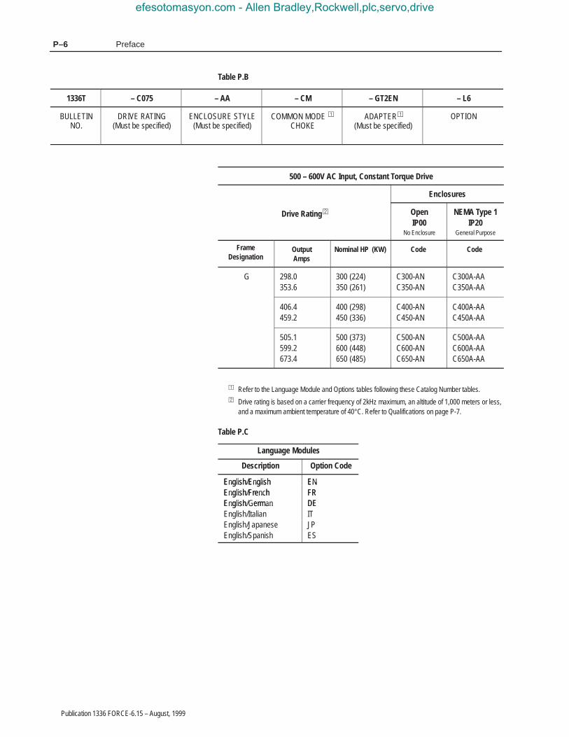
Table P.B
1336T – C075 – AA – CM – GT2EN – L6
BULLETINNO.
DRIVE RATING(Must be specified)
ENCLOSURE STYLE(Must be specified)
COMMON MODE �
CHOKE ADAPTER�
(Must be specified)OPTION
500 – 600V AC Input, Constant Torque Drive
Enclosures
Drive Rating� OpenIP00
No Enclosure
NEMA Type 1IP20
General Purpose
FrameDesignation
OutputAmps
Nominal HP (KW) Code Code
G 298.0353.6
300 (224)350 (261)
C300-ANC350-AN
C300A-AAC350A-AA
406.4459.2
400 (298)450 (336)
C400-ANC450-AN
C400A-AAC450A-AA
505.1599.2673.4
500 (373)600 (448)650 (485)
C500-ANC600-ANC650-AN
C500A-AAC600A-AAC650A-AA
� Refer to the Language Module and Options tables following these Catalog Number tables.� Drive rating is based on a carrier frequency of 2kHz maximum, an altitude of 1,000 meters or less,
and a maximum ambient temperature of 40°C. Refer to Qualifications on page P-7.
Table P.C
Language Modules
Description Option Code
English/English ENEnglish/EnglishEnglish/French
ENFREnglish/French
English/GermanFRDEEnglish/German
English/Italiann li /Ja an
DEITJP
n li /ItalianEnglish/Japanese
n li / ani
ITJPn li /Ja an
English/SpanishJPES
efesotomasyon.com - Allen Bradley,Rockwell,plc,servo,drive

Preface P–7
Publication 1336 FORCE-6.15 – August, 1999
Table P.D
Options
Code� Description � Code Description �
Human Interface Modules, NEMA Type 1 (IP 20) Communication Options
HABHAPHA1HA2
Blank – No FunctionalityProgrammer OnlyProgrammer, LCD/Analog PotProgrammer, LCD/Digital Pot
GM1GM2GM3
Single Point Remote I/ORS-232/422/485, DF1RS-232/422/485, DH485
Human Interface Modules, NEMA Type 4 (IP 56) Control Interface Options
HFBHFPHF1HF2
Blank – No FunctionalityProgrammer OnlyProgrammer, LCD/Analog PotProgrammer, LCD/Digital Pot
L4L5L6
TTL Contacts24V DC115V AC
Human Interface Modules, NEMA Type 12 (IP 54)
HJBHJPHJ1HJ2
Blank – No FunctionalityProgrammer OnlyProgrammer, LCD/Analog PotProgrammer, LCD/Digital Pot
� Must be used in conjunction with a standard adapter option –GT2EN� For a more functionally complete description of each option refer to Publication 1336 FORCE-1.0.
Drive Rating Qualifications
Several factors can affect drive rating. If more than one factor exists,derating percentages must be multiplied. For example, if a 14-ampdrive is installed at a 2km (6,600 ft.) altitude and has a 2%high-input line voltage, the actual amp rating is:14 x 94% altitudederating x 96% high-input line derating = 12.6 amps
Enclosure Type
The first character, A, indicates the Enclosure Code.
The second character indicates the type of enclosure shipped fromthe factory:
Table P.EEnclosure Type Code Description
EnclosureType Code Description
F NEMA Type 1 (IP 65)
efesotomasyon.com - Allen Bradley,Rockwell,plc,servo,drive

PrefaceP–8
Publication 1336 FORCE-6.15 – August, 1999
To help differentiate parameter names and display text from othertext in this manual, the following conventions will be used:
• Parameter Names will appear in [brackets].
• Display Text will appear in “quotes”.
The following is a list of conventions used throughout this manual,and definitions of the conventions. For a list of terminology anddefinitions, refer to the Glossary in the back of this manual.
Auxiliary Input
The Auxiliary Input is a terminal connection on the Control InterfaceBoard. This connection provides an external input for use as anAuxiliary Interlock. Unless this interlock is closed, the drive will befaulted with an Auxiliary Fault.
Auxiliary Interlock
The Auxiliary Interlock is a user supplied circuit consisting of reset,overload, or other interlocking circuitry. The Interlock is wired to thedrive Auxiliary input.
Bit
A bit is a single character or status point used in programmablelogic. Eight bits form a BYTE, 16 bits form a word. Driveparameters are actually eight bits or 16 bit words.
Check
To check means to examine either the physical condition ofsomething or the setting of some control, such as a Parameter.Checking a drive board or component may also requiremeasurements and tests.
Connector
A connector connects one drive board to another. Connectors comein two designs, male and female. Male connectors are stationary andcontain pins, which are sometimes joined by jumpers. Femaleconnectors are at the ends of wires or ribbon cables and plug intomale connectors.
Conventions
efesotomasyon.com - Allen Bradley,Rockwell,plc,servo,drive

Preface P–9
Publication 1336 FORCE-6.15 – August, 1999
Default
When a drive function defaults, it automatically changes to apre-programmed setting.
Enable Input
The Enable Input is a terminal connection on the Control InterfaceBoard. This connection provides an external input to enable ordisable the Drive Output section. It must be true to permit the driveto operate.
False
False refers to a logical false state. For instance, a Control Interfacesignal on TB3 is false when the input contact is open or theappropriate voltage is not applied to the Control Interface Board.
Jumper
A jumper completes a circuit between two pins within a maleconnector on a drive board. In the absence of certain optionalequipment using female connectors, jumpers are applied to certainpins within a male connector to complete specific and necessarycircuits.
Control Interface Board
A Control Interface Board plugs into connectors J7 and J9, locatedon the lower portion of the Standard Adapter Board. This board isidentified as L4, L5, or L6 and provides optional control wiringconfigurations for a drive.
Parameter
Parameters are programmable drive functions that define variousoperating functions or status displays of a drive. Refer to Bulletin1336 FORCE Adjustable Frequency AC Drive User Manual forParameter details.
Press
Press a button on the Human Interface Module to change Parametersettings and drive functions.
efesotomasyon.com - Allen Bradley,Rockwell,plc,servo,drive

PrefaceP–10
Publication 1336 FORCE-6.15 – August, 1999
True
True refers to a logical true state. For instance, a Control Interfacesignal on TB3 is true when: L4 contact input is closed, L5 inputterminal registers 24V, or L6 input terminal registers 115V AC.
The following lists other Allen-Bradley publications that apply to the1336 FORCE Adjustable Frequency AC Drives:
• Product Data Drive Tools Software (9303-2.0)
• Bulletin 1201 Graphic Programming Terminal User Manual(1201-5.0)
• Product Pricing Bulletin (1336 FORCE-3.0)
• 1336 FORCE Field Oriented Control User Manual (1336FORCE-5.12)
• 1336 Force PLC Communications Adapter User Manual (1336 FORCE-5.13)
• Renewal Parts List (1336-6.5)
• Options Manuals/Instructions
Related Publications
efesotomasyon.com - Allen Bradley,Rockwell,plc,servo,drive

Chapter 1
Publication 1336 FORCE-6.15 – August, 1999
Control Logic Wiring and Adapters
This chapter introduces you to terminal block locations and wiring,and adapter locations and functions.
This chapter illustrates and describes Standard Adapter Board:
• Control Logic Interface Options L4, L5, and L6, includingTerminal Block TB3
• TB3 input mode selections and functions
• TB3, TB5, TB6, TB7 terminal designations
This chapter illustrates and describes the following terminaldesignations for the PLC Comm Adapter Board:
• TB20
• TB21
Important: All printed circuit boards, except the Main ControlBoard assembly, are referenced to negative ground(–bus).
!ATTENTION: Some printed circuit boards and drivecomponents may contain hazardous voltage levels.Remove power before you disconnect or reconnectwires, and before you remove or replace fuses andcircuit boards. Verify bus voltage by measuring thevoltage between the Negative Capacitor Bus and bothends of all three 350 amp fuses. An open fuse does notshow voltage across both ends of the fuse. Failure tomeasure voltage at both ends of the fuses may result indeath or serious injury. Refer to Figure 2.5. Do notattempt to service the drive until the bus voltage hasdischarged to zero volts.
!ATTENTION: This assembly contains parts andsub-assemblies that are sensitive to electrostatic discharge.Static control precautions are required when servicing thisassembly. Component damage may result if you ignoreelectrostatic discharge control procedures. If you are notfamiliar with static control procedures, referenceAllen-Bradley Publication 8000–4.5.2, Guarding AgainstElectrostatic Discharge, or any other applicable ESDprotection handbook.
Chapter Objectives
Chapter Overview
efesotomasyon.com - Allen Bradley,Rockwell,plc,servo,drive

1–2 Control Logic Wiring and Adapters
Publication 1336 FORCE-6.15 – August, 1999
Figure 1.1Terminal Block Locations
TB11
TB11
AB0770A
JOG
ESC SEL
Main ControlBoard
StandardAdapterBoard
TB10 Encoder
TB5, TB6, TB7Control and
Signal Wiring
TB3 ControlL–Option Board
Control InterfaceL-Option Board
CommunicationChannels
Main ControlBoard
PLC CommBoard
TB10 Encoder
TB20, TB21Control and
Signal Wiring
!ATTENTION: The National Electric Code (NEC)and local codes outline provisions for safely installingelectrical equipment. Installation must comply withspecifications regarding wire types, conductor sizes,branch circuit protection and disconnect devices.Failure to do so may result in personal injury and/orequipment damage.
efesotomasyon.com - Allen Bradley,Rockwell,plc,servo,drive

1–3Control Logic Wiring and Adapters
Publication 1336 FORCE-6.15 – August, 1999
The Control Interface L-Option Board provides a means ofinterfacing various signals and commands to the 1336 FORCE by usingcontact closures.
Three different versions of the option are available:
L4 Contact Closure Interface1
L5 +24V AC/DC Interface
L6 115V AC Interface1 Uses internal +5V DC supply.
The user inputs are connected to the option board through TB3. TheL4, L5 and L6 options each have nine control inputs. The function ofeach input must be selected through programming as explained laterin this section.
Control Interface L-Option Board Jumpers
Important: If the Control Interface Board is being installed,Standard Adapter Board jumpers at pins 3 & 4 and 17& 18 of J10 must be removed. If this board is removed,these jumpers must be reinstalled and the [Input Mode]parameter must be programmed to “1”.
Figure 1.2Jumper Locations
AB0766A
Jumper J10 (Located onStandard Adapter Board)
Control Interface Option
efesotomasyon.com - Allen Bradley,Rockwell,plc,servo,drive

1–4 Control Logic Wiring and Adapters
Publication 1336 FORCE-6.15 – August, 1999
Available Inputs
A variety of combinations made up of the following inputs areavailable.
Start Enable
Stop/Clear Fault Auxiliary
Reverse 2 Stop Mode Selects
Digital Potentiometer (MOP) Run Forward
2 Accel/Decel Rates Run Reverse
3 Speed Selects Local Control
The available combinations are shown in Figure 1.4. Programmingthe [Input Mode] parameter to one of the Input Mode numbers listedselects that combination of input functions.
Important: The [Input Mode] parameter can be changed at anytime; however, programming changes will not takeeffect until power has been cycled to the drive. Whenchanging an input mode, it is important to note that thecorresponding inputs to TB3 may also change.
The programming options of the Control Interface Option allow youto select an input combination to meet the needs of a specificinstallation. Appropriate selection of a combination may be done byusing Table 1.A. First determine the type of start/stop/directioncontrol desired. Then select the remaining control functionsavailable. After selecting a group of Input Modes use Table 1.A forspecific mode selection. Record the selected mode number below.
Selected Mode Number:
For local programming and control information, refer to the 1336FORCE User Manual.
Standard AdapterLocal Programming
efesotomasyon.com - Allen Bradley,Rockwell,plc,servo,drive

1–5Control Logic Wiring and Adapters
Publication 1336 FORCE-6.15 – August, 1999
Table 1.AInput Mode Selection
Start/Stop Type Direction Control Communication CompatibilityMode(s)to Use
Stop & EnableOnly
None Control must be provided by HIM or Communication Option. 1
MomentaryPushbutton(3 Wire)
Maintained Switch(Open-Forward,Closed-Reverse)
Start/Stop – works in parallel with HIM and Communication Options.Direction Control will not work in parallel with HIM or CommunicationOptions. User must select direction control from either HIM andCommunication Options or TB3 input.
2 – 6
MomentaryPushbutton
(3 Wire)
Momentary Pushbuttons(Forward and Reverse)
Start/Stop – works in parallel with HIM and Communication Options.Direction – works in parallel with HIM or Communication Options. 7 – 11
Maintained switches for combined run and directioncontrol (2 wire, Run Forward, Run Reverse)
Start/Stop – not compatible with HIM or Communication Options.Direction – not compatible with HIM or Communication Options.
12 – 16
The maximum and minimum wire sizes accepted by TB3 is 2.1 and0.30 mm2 (14 and 22 AWG). Maximum torque for all terminals is0.9 – 1.13 N-m (8 – 10 in.-lb).
Figure 1.3TB3 Terminal Designations
AB0550A
19 20 21 22 23 24 25 26 27 28 29 30
Inpu
t 1
Inpu
t 2 (S
top)
Com
mon
Inpu
t 3
Inpu
t 4
Inpu
t 5
Com
mon
Inpu
t 6
Inpu
t 7
Inpu
t 8
Com
mon
Enab
le
efesotomasyon.com - Allen Bradley,Rockwell,plc,servo,drive

1–6 Control Logic Wiring and Adapters
Publication 1336 FORCE-6.15 – August, 1999
Figure 1.4Input Mode Selection and Typical TB3 Connections
19
20
21
22
23
24
25
26
27
28
29
30
Status
Common
Status
Status
Status
Common
Status
Status
Status
Common
[Input Mode] 1Factory Default
19
20
21
22
23
24
25
26
27
28
29
30
Start
Common
Reverse
Common
Common
Jog StopType
2ndAccel
DigitalPot Up
Jog
Speed Speed 2ndDecel
DigitalPot Dn
Local
2 3 4 5 6
Mode
[Input Mode] 2 – 6
See Table 1.B. 1
Drive must be stopped to take Local Control.Control by all other adapters is disabled (except Stop).
2
These inputs must be present before drive will start. 3
User
Con
nect
ions
User
Con
nect
ions
AB0290B
Momentary
Maintained
AT
TE
NT
ION
:pr
oper
ly u
nles
s a
SC
AN
port
opt
ion
is c
onne
cted
to
the
driv
e. T
o as
sure
pro
per
JOG
fun
ctio
n, in
stal
l at
leas
t on
eof
the
fol
low
ing:
1201
-HA
P,
1201
-HA
1, 1
201-
HA
2, 1
336-
GM
1. A
pplie
sto
130
5 w
ith f
irmw
are
FR
N 2
.01
or e
arlie
r an
d 13
36
PLU
S w
ith L
angu
age
Mod
ule
1336
S-E
N f
irmw
are
FR
N1.
05 o
r ea
rlier
.The
JO
G f
unct
ion
will
not
ope
rate
Enable3
Enable3
Stop/Fault Reset3
Stop/Fault Reset3
Auxiliary3
Speed Select 21
Speed Select 11
Select 31 Select 31 Control2
Note: If this mode is selected, the status of allinputs can be read at the [Input Status] parameter.However, only “Stop/Fault Reset” and “Enable” willhave control function.
Three-Wire Control with Single-Source Reversing
efesotomasyon.com - Allen Bradley,Rockwell,plc,servo,drive

1–7Control Logic Wiring and Adapters
Publication 1336 FORCE-6.15 – August, 1999
Momentary
Maintained
Run Forward
Common
Run Reverse
Common
Common
Local StopType
2ndAccel
DigitalPot Up
Local
Speed Speed 2ndDecel
DigitalPot Dn
StopType
12 13 14 15 16Mode
[Input Mode] 12 – 16Two-Wire Control, Single-Source Control
19
20
21
22
23
24
25
26
27
28
29
30
Start
Common
Common
Common
Forward Forward DigitalPot Dn
Forward 2ndAccel
Jog Speed Speed DigitalPot Up
1stDecel
[Input Mode] 7 – 11Three-Wire Control with Multi-Source Reversing
Reverse Reverse DigitalPot Up
Reverse 1stAccel
7 8 9 10 11Mode
Speed Speed Speed DigitalPot Dn
2ndDecel
19
20
21
22
23
24
25
26
27
28
29
30
User
Con
nect
ions
User
Con
nect
ions
See Table 1.B. 1
Drive must be stopped to take Local Control.Control by all other adapters is disabled (except Stop).
2
AB0291B
These inputs must be present before drive will start. 3
AT
TE
NT
ION
:pr
oper
ly u
nles
s a
SC
AN
port
opt
ion
is c
onne
cted
to
the
driv
e. T
o as
sure
pro
per
JOG
fun
ctio
n, in
stal
l at
leas
t on
eof
the
fol
low
ing:
1201
-HA
P,
1201
-HA
1, 1
201-
HA
2, 1
336-
GM
1. A
pplie
sto
130
5 w
ith f
irmw
are
FR
N 2
.01
or e
arlie
r an
d 13
36
PLU
S w
ith L
angu
age
Mod
ule
1336
S-E
N f
irmw
are
FR
N1.
05 o
r ea
rlier
.The
JO
G f
unct
ion
will
not
ope
rate Stop/Fault Reset3
Auxiliary3
Speed Select 11
Enable3
Stop/Fault Reset3
Auxiliary3
Speed Select 21
Speed Select 11
Enable3
Select 21 Select 21 Select 21
Select 31 Select 31
Control2 Control2
Select 31 Select 31
efesotomasyon.com - Allen Bradley,Rockwell,plc,servo,drive

1–8 Control Logic Wiring and Adapters
Publication 1336 FORCE-6.15 – August, 1999
Table 1.BSpeed Select Input State vs. Velocity Reference Source
Para 52TB3
Speed Select 3Bit 14
Terminal 26
Speed Select 2Bit 13
Terminal 27
Speed Select 1B12
Terminal 28Velocity Reference
Source
O O O Last State
O O X External Reference 1
O X O Preset Speed 1
O X X Preset Speed 2
X O O Preset Speed 3
X O X Preset Speed 4
X X O Preset Speed 5
X X X External Reference 2
O = Open — Input Removed
X = Closed — Input Present
The DIP switches and jumpers on the PLC Communications Boardhave been preset at the factory. Communication is received throughChannels A and B. This communication protocol is defined throughSW U2 – U5. If switches or jumpers require reconfiguration, refer tothe 1336 FORCE PLC Communications Adapter User Manual.
Figure 1.5PLC Comm Adapter Reference Signal Connections
AB0551A
1 2 3 4 5 6 7 8 9 10 11 12 13 14 15 16 17 18 19
AnalogOut 1
AnalogOut 2
AnalogOut 3
AnalogOut 4
AnalogIn1
AnalogIn2
AnalogIn3
AnalogIn4
+10 Comm–10
1 2 3 4 5 6 7 8 9 10
DriveEnable
Stop
MotorThermo
ExtFault
CommonFaultRelay
TB20 TB21
efesotomasyon.com - Allen Bradley,Rockwell,plc,servo,drive

1–9Control Logic Wiring and Adapters
Publication 1336 FORCE-6.15 – August, 1999
Table 1.CPLC Comm Adapter Reference Signal Connections
Terminal Block Terminal Number(s) Signal
TB20 1 Drive Enable (NO)
2 Motor Thermoguard (NC)
3 Normal Stop (NC)
4 External Fault (NC)
5
6 Input Common
7
8 Fault Output (NC)
9 Fault Output (COM)
10 Fault Output (NO)
TB21 1 OUT 1
2 COM 1
3 COM 2
4 OUT 2
5 OUT 3
6 COM 3
7 OUT 4
8 COM 4
9 IN 1+
10 IN 1–
11 IN 2+
12 IN 2–
13 IN 3+
14 IN 3–
15 IN 4+
16 IN 4–
17 +10V
18 COM
19 –10V
Human Interface Module
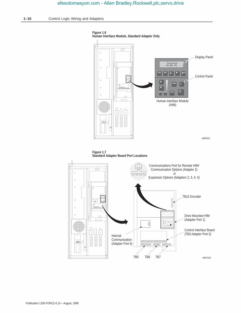
When the drive-mounted HIM is supplied, it will be connected asPort 1 (refer to Figure 1.7). The HIM can be divided into twosections; Display Panel and Control Panel. The Display Panelprovides a means of programming the drive and viewing the variousoperating parameters. The Control Panel allows different drivefunctions to be controlled. For HIM operation, refer to the 1336FORCE Field Oriented Control User Manual.
Important: The operation of HIM functions depends upon driveparameter settings. Default parameter values allow fullHIM functionality.
Adapters andCommunication Ports
efesotomasyon.com - Allen Bradley,Rockwell,plc,servo,drive
1–10 Control Logic Wiring and Adapters
Publication 1336 FORCE-6.15 – August, 1999
Figure 1.6Human Interface Module, Standard Adapter Only
AB0542A
Display Panel
Control Panel
Human Interface Module(HIM)
Figure 1.7Standard Adapter Board Port Locations
AB0701B
JOG
ESC SEL
TB10 Encoder
2 3 4 5
2 3Communications Port for Remote HIM/
Communication Options (Adapter 2) or
Expansion Options (Adapters 2, 3, 4, 5)
Control Interface Board(TB3 Adapter Port 0)
Drive Mounted HIM(Adapter Port 1)
TB5
InternalCommunication(Adapter Port 6)
TB6 TB7
efesotomasyon.com - Allen Bradley,Rockwell,plc,servo,drive

1–11Control Logic Wiring and Adapters
Publication 1336 FORCE-6.15 – August, 1999
Figure 1.8PLC Comm Adapter Board Port Locations
AB0702B
TB20
CommunicationsChannels Ports 6, 7
MainControlBoard
PLC CommBoard SCAN port 1
SCAN port 2
TB21
efesotomasyon.com - Allen Bradley,Rockwell,plc,servo,drive

1–12 Control Logic Wiring and Adapters
Publication 1336 FORCE-6.15 – August, 1999
HIM Removal
!ATTENTION: Some voltages present behind thedrive front cover are at incoming line potential. Toavoid an electric shock hazard, use extreme cautionwhen removing/replacing the HIM.
For handheld operation, the module can be removed and located upto 10 meters (33 feet) from the drive.
Important: Power must be removed from the drive or Bit 1 of the[Logic Mask] parameter must be set to “0” to allowremoval of the HIM module without causing aCommunication Fault. Setting Bit 1 of the [LogicMask] parameter to “0” allows HIM removal whilepower is applied to the drive. Note that this alsodisables all HIM control functions except Stop.
Important: To remove the module:
1. Ensure that power has been removed or [Logic Mask] has beenset to “0”.
2. Take the drive front cover off and simply slide the module downand out of its cradle. Remove cable from module.
3. Connect the appropriate cable between the HIM and theCommunications Port (Adapter 2, 3, 4, or 5).
4. Reverse the above steps to replace the module. Apply power or resetBit 1 of the [Logic Mask] parameter to “1” to enable HIM control.
HIM Operation
When power is first applied to the drive, the HIM will cycle througha series of displays. These displays will show drive ID andcommunication status. Upon completion, the Status Display (refer toFigure 1.9) will be shown. This display shows the current status ofthe drive (i.e. Stopped, Running, etc.) or any faults that may bepresent (Not Enabled, etc.). Refer to the 1336 FORCE Field OrientedControl User Manual.
Figure 1.9Status Display
Stopped+0.00 Hz
efesotomasyon.com - Allen Bradley,Rockwell,plc,servo,drive

1–13Control Logic Wiring and Adapters
Publication 1336 FORCE-6.15 – August, 1999
GPT Description
The optional GPT (Figure 1.10) is a remote device with a 1.8 meter(6 foot) long cable. The GPT offers a 40-by-8 character display thatcan also be used as a graphics display to show trending graphs. ForGPT operation, refer to the 1336 FORCE Field Oriented ControlUser Manual. See also the 1201 GPT User Manual.
Important: Main Menu screens are dynamic and will change basedon functionality provided by adapter and drive status.
Figure 1.10Graphic Programming Terminal
AB0554A
F1 F2 F3 F4
7 8 9
4 5 6
1 2 3
. 0 +/–
+D E F
ALT PRESET 4 PRESET 5 XREF 1
PRESET 1 PRESET 2 PRESET 3ESC
–
JOG
Graphic ProgrammingTerminal
efesotomasyon.com - Allen Bradley,Rockwell,plc,servo,drive

1–14 Control Logic Wiring and Adapters
Publication 1336 FORCE-6.15 – August, 1999
Drive Tools software is a Windows 3.1 compatible family ofapplication programs allowing the user to perform programming,monitoring, and diagnostic operations on Allen-Bradley AC and DCdigital drive products. The software consists of five Windowsapplications. For operation, refer to the Product Data Drive ToolsSoftware manual.
All control functions in the 1336 FORCE are performed through theuse of parameters that can be changed with a programming terminalor Drive Tools. Refer to an overview Block Diagram of the ControlFirmware Function in the 1336 FORCE Field Oriented Control UserManual.
Feedback information is derived from hardware devices as part ofthe process equipment used. Analog signals are converted to digitalsignals for use by the drive. Control signals may be provided to thedrive by one of two Adapter Boards.
All setup and operation information used by the drive is stored in asystem parameter table. Every parameter, including Setup andConfiguration parameters (Sources and Sinks), has an entry in theparameter table. For example, parameter 101 is named the “VelocityReference 1 HI (whole)” parameter and contains a number valuerepresenting the velocity reference. The velocity reference canoriginate from an external control device such as a potentiometerconnected to the analog input of an Adapter board or a signal comingin via RIO from a PLC. Refer to the 1336 FORCE User Manual,Publication 1336 FORCE-5.12.
Drive Tools
Control Firmware Function
efesotomasyon.com - Allen Bradley,Rockwell,plc,servo,drive

Chapter 2
Publication 1336 FORCE-6.15 – August, 1999
Disassembly and AccessProcedures
This chapter describes general disassembly procedures required toaccess internal drive components.
!ATTENTION: Some printed circuit boards and drivecomponents may contain hazardous voltage levels.Remove and lock out power before you disconnect orreconnect wires, and before you remove or replacefuses and circuit boards. Verify bus voltage bymeasuring the voltage between the Negative CapacitorBus and both ends of all three 350 amp fuses. An openfuse does not show voltage across both ends of thefuse. Failure to measure voltage at both ends of thefuses may result in death or serious injury. Refer toFigure 2.5. Do not attempt to service the drive until thebus voltage has discharged to zero volts.
!ATTENTION: Servicing energized industrial controlequipment can be hazardous. Electrical shock, burns,or unintentional actuation of controlled industrialequipment may cause death or serious injury. Followthe safety-related practices of NFPA 70E, ElectricalSafety for Employee Workplaces, when working on ornear energized equipment. Do not work alone onenergized equipment.
Chapter Objectives
Disassembly and Access Overview
efesotomasyon.com - Allen Bradley,Rockwell,plc,servo,drive
2–2 Disassembly and Access Procedures
Publication 1336 FORCE-6.15 – August, 1999
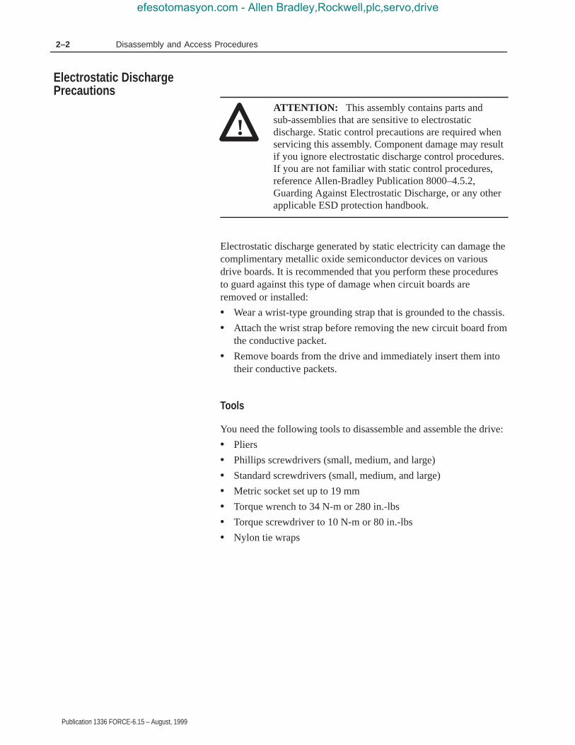
!ATTENTION: This assembly contains parts andsub-assemblies that are sensitive to electrostaticdischarge. Static control precautions are required whenservicing this assembly. Component damage may resultif you ignore electrostatic discharge control procedures.If you are not familiar with static control procedures,reference Allen-Bradley Publication 8000–4.5.2,Guarding Against Electrostatic Discharge, or any otherapplicable ESD protection handbook.
Electrostatic discharge generated by static electricity can damage thecomplimentary metallic oxide semiconductor devices on variousdrive boards. It is recommended that you perform these proceduresto guard against this type of damage when circuit boards areremoved or installed:
• Wear a wrist-type grounding strap that is grounded to the chassis.
• Attach the wrist strap before removing the new circuit board fromthe conductive packet.
• Remove boards from the drive and immediately insert them intotheir conductive packets.
Tools
You need the following tools to disassemble and assemble the drive:
• Pliers
• Phillips screwdrivers (small, medium, and large)
• Standard screwdrivers (small, medium, and large)
• Metric socket set up to 19 mm
• Torque wrench to 34 N-m or 280 in.-lbs
• Torque screwdriver to 10 N-m or 80 in.-lbs
• Nylon tie wraps
Electrostatic DischargePrecautions
efesotomasyon.com - Allen Bradley,Rockwell,plc,servo,drive

2–3Disassembly and Access Procedures
Publication 1336 FORCE-6.15 – August, 1999
Torque Sequence
When mounting components to a drive’s heat sink, component-fastenertorque sequences and tolerances are crucial to component-to-heat sinkheat dissipation.
!ATTENTION: Component can be damaged iftemporary tightening procedure is not performed tospecification.
The following illustrates temporary and final tightening sequencesfor components fastened to a heat sink using two, four, and sixscrews. Temporary torque is 1/3 (33%) of final torque, exceptsix-point mountings, which require 0.5 N-m (4 in.-lb). The numericillustration labels are for your assistance. Drive components do notcarry these labels.
Figure 2.1Two-Point Mounting
21
AB0016A
12
21
Temporary Tighten
Final Tighten
Two–Point Mounting
Fastener TorqueSpecifications
efesotomasyon.com - Allen Bradley,Rockwell,plc,servo,drive

2–4 Disassembly and Access Procedures
Publication 1336 FORCE-6.15 – August, 1999
Figure 2.2Four-Point Mounting
AB0017A
1
2
3
4
1 32 4
4 123
Temporary Tighten
Final Tighten
Four–Point Mounting
Figure 2.3Six-Point Mounting
AB0624B
6
3
2
1
4
5
Do not exceed 0.4 Newton-meters (3 in.-lb) on initial torque or 3.8Newton-meters (32 in.-lb) final torque of all six screws.
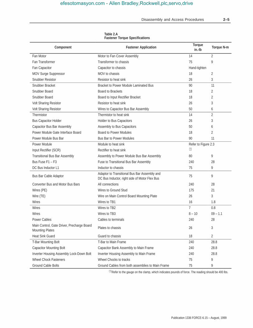
Torque Specifications
The following table lists fastener locations by component, how thefasteners are used, and torque specifications. Refer to TorqueSequence in this chapter for fastening two-point, four-point andsix-point components to the heat sink.
�
efesotomasyon.com - Allen Bradley,Rockwell,plc,servo,drive
2–5Disassembly and Access Procedures
Publication 1336 FORCE-6.15 – August, 1999
Table 2.AFastener Torque Specifications
Component Fastener ApplicationTorquein.-lb
Torque N-m
Fan Motor Motor to Fan Cover Assembly 14 2
Fan Transformer Transformer to chassis 75 9
Fan Capacitor Capacitor to chassis Hand-tighten
MOV Surge Suppressor MOV to chassis 18 2
Snubber Resistor Resistor to heat sink 26 3
Snubber Bracket Bracket to Power Module Laminated Bus 90 11
Snubber Board Board to Brackets 18 2
Snubber Board Board to Input Rectifier Bracket 18 2
Volt Sharing Resistor Resistor to heat sink 26 3
Volt Sharing Resistor Wires to Capacitor Bus Bar Assembly 50 6
Thermistor Thermistor to heat sink 14 2
Bus Capacitor Holder Holder to Bus Capacitors 26 3
Capacitor Bus Bar Assembly Assembly to Bus Capacitors 50 6
Power Module Gate Interface Board Board to Power Modules 18 2
Power Module Bus Bar Bus Bar to Power Modules 90 11
Power Module Module to heat sink Refer to Figure 2.3
Input Rectifier (SCR) Rectifier to heat sink �
Transitional Bus Bar Assembly Assembly to Power Module Bus Bar Assembly 80 9
Bus Fuse F1 – F3 Fuse to Transitional Bus Bar Assembly 240 28
DC Bus Inductor L1 Inductor to chassis 75 9
Bus Bar Cable AdaptorAdaptor to Transitional Bus Bar Assembly and DC Bus Inductor, right side of Motor Flex Bus
75 9
Converter Bus and Motor Bus Bars All connections 240 28
Wires (PE) Wires to Ground Stud 175 21
Wire (TE) Wire on Main Control Board Mounting Plate 26 3
Wires Wires to TB1 16 1.8
Wires Wires to TB2 7 0.8
Wires Wires to TB3 8 – 10 09 – 1.1
Power Cables Cables to terminals 240 28
Main Control, Gate Driver, Precharge BoardMounting Plates
Plates to chassis 26 3
Heat Sink Guard Guard to chassis 18 2
T-Bar Mounting Bolt T-Bar to Main Frame 240 28.8
Capacitor Mounting Bolt Capacitor Bank Assembly to Main Frame 240 28.8
Inverter Housing Assembly Lock-Down Bolt Inverter Housing Assembly to Main Frame 240 28.8
Wheel Chock Fasteners Wheel Chocks to tracks 75 9
Ground Cable Bolts Ground Cables from both assemblies to Main Frame 75 9�Refer to the gauge on the clamp, which indicates pounds of force. The reading should be 400 lbs.
efesotomasyon.com - Allen Bradley,Rockwell,plc,servo,drive

2–6 Disassembly and Access Procedures
Publication 1336 FORCE-6.15 – August, 1999
Opening the Drive Enclosure
Figure 2.4Drive Enclosure
AB0595B
PC BoardMounting Frame
Disassembly andAccess Procedures
efesotomasyon.com - Allen Bradley,Rockwell,plc,servo,drive

2–7Disassembly and Access Procedures
Publication 1336 FORCE-6.15 – August, 1999
Opening
!ATTENTION: Disconnect and lock out power fromthe drive before disassembling the drive. Failure todisconnect power may result in death or serious injury.Verify bus voltage by measuring the voltage between theNegative Capacitor Bus and both ends of all three 350amp fuses. An open fuse does not show voltage acrossboth ends of the fuse. Failure to measure voltage at bothends of the fuses may result in death or serious injury.Refer to Figure 2.5. Do not attempt to service the driveuntil the bus voltage has discharged to zero volts.
!ATTENTION: Wear a wrist-type grounding strapwhen servicing 1336 FORCE Drives. Failure to protectdrive components against ESD may damage drivecomponents. Refer to Electrostatic DischargePrecautions at the beginning of this chapter.
1. Remove power from the drive.
2. Turn the enclosure door latches 90 degrees counterclockwise toopen the enclosure door.
3. Turn the latches, located on the left side of the PC BoardMounting frame, to open the PC Board Mounting Frame. Refer toFigure 2.4.
4. Check for zero volts between +DC and –DC. Refer to Figure 2.5.
efesotomasyon.com - Allen Bradley,Rockwell,plc,servo,drive

2–8 Disassembly and Access Procedures
Publication 1336 FORCE-6.15 – August, 1999
Figure 2.5DC Voltage Check
AB0637B
–DC (NegativeCapacitor Bus)
+DC
Check All ThreeBus Fuses
!ATTENTION: A blown fuse can create a hazard ofshock which may result in death or serious injury.Check voltage between the bus bar and both ends of allthree fuses.
5. Check for the absence of control voltage at:
• TB20 and TB21 on drives using a PLC Comm Adapter Board• TB5, TB6, and TB7 on drives using a Standard Adapter Board
6. Remove the customer-supplied wiring from the drive.
Closing the Drive Enclosure
Close the Drive Enclosure in reverse order of opening.
!ATTENTION: Replace all guards before applyingpower to the drive. Failure to replace guards may resultin death or serious injury.
efesotomasyon.com - Allen Bradley,Rockwell,plc,servo,drive

2–9Disassembly and Access Procedures
Publication 1336 FORCE-6.15 – August, 1999
Removing the Control Interface L-Option Board Mod –L4, –L5, or–L6
Figure 2.6Control Interface L-Option Board
AB0759A
Control InterfaceL-Option Board
Terminal Strip TB3
Main Control Board
Removal
!ATTENTION: Disconnect and lock out power fromthe drive before disassembling the drive. Failure todisconnect power may result in death or serious injury.Verify bus voltage by measuring the voltage betweenthe Negative Capacitor Bus and both ends of all three350 amp fuses. An open fuse does not show voltageacross both ends of the fuse. Failure to measure voltageat both ends of the fuses may result in death or seriousinjury. Refer to Figure 2.5. Do not attempt to service thedrive until the bus voltage has discharged to zero volts.
efesotomasyon.com - Allen Bradley,Rockwell,plc,servo,drive

2–10 Disassembly and Access Procedures
Publication 1336 FORCE-6.15 – August, 1999
!ATTENTION: Wear a wrist-type grounding strapwhen servicing 1336 FORCE Drives. Failure to protectdrive components against ESD may damage drivecomponents. Refer to Electrostatic DischargePrecautions at the beginning of this chapter.
Important: Before you remove connections and wires from thedrive components, mark the connections and wires tocorrespond with their component connections andterminals to prevent incorrect wiring during assembly.
1. Remove power from the drive.
2. Open the PC Board Mounting Frame. Refer to Opening the DriveEnclosure in this chapter.
3. Check for zero volts between +DC and –DC. Refer to Figure 2.5.
4. Check for the absence of control voltage at TB5, TB6, and TB7on the Standard Adapter Board.
5. Remove all wires from Control Interface Board TB3.
6. Loosen the two captive screws fastening the Control InterfaceBoard to the Standard Adapter Board.
7. Grip the right and left sides of the Control Interface Board andpull the board straight out from the Standard Adapter Board.
Installation
Install the Control Interface Board in reverse order of removal.
!ATTENTION: Replace all guards before applyingpower to the drive. Failure to replace guards may resultin death or serious injury.
efesotomasyon.com - Allen Bradley,Rockwell,plc,servo,drive

2–11Disassembly and Access Procedures
Publication 1336 FORCE-6.15 – August, 1999
Removing the Main Control Board
Figure 2.7Main Control Board and Mounting Plate
AB0704A
Main ControlBoard
HIM (StandardAdapter Board only)
TB10Connector J7
Connector J1Standard
Adapter Board
Ground Stud
Connector J5
Control Board/AdapterMounting Plate
Removal
!ATTENTION: Disconnect and lock out power fromthe drive before disassembling the drive. Failure todisconnect power may result in death or serious injury.Verify bus voltage by measuring the voltage betweenthe Negative Capacitor Bus and both ends of all three350 amp fuses. An open fuse does not show voltageacross both ends of the fuse. Refer to Figure 2.5. Donot attempt to service the drive until the bus voltagehas discharged to zero volts.
efesotomasyon.com - Allen Bradley,Rockwell,plc,servo,drive

2–12 Disassembly and Access Procedures
Publication 1336 FORCE-6.15 – August, 1999
!ATTENTION: Wear a wrist-type grounding strapwhen servicing 1336 FORCE Drives. Failure to protectdrive components against ESD may damage drivecomponents. Refer to Electrostatic DischargePrecautions at the beginning of this chapter.
Important: Before you remove connections and wires from thedrive components, mark the connections and wires tocorrespond with their component connections andterminals to prevent incorrect wiring during assembly.
1. Remove power from the drive.
2. Open the PC Board Mounting Frame. Refer to Opening the DriveEnclosure in this chapter.
3. Check for zero volts between +DC and –DC. Refer to Figure 2.5.
4. Check for the absence of control voltage at:
• TB20 and TB21 on drives using a PLC Comm Adapter Board• TB5, TB6, and TB7 on drives using a Standard Adapter Board
5. Disconnect the following from the Main Control Board:
• J1 connector• J5 ribbon cable connector• Stake-on ground wire connector• All wires from the terminals on TB10
6. Remove the screws fastening the Main Control Board to theControl Board/Adapter Mounting Plate.
7. Slide the Main Control Board upward to release it from theslide-mount stand-offs and connector J7.
8. Store the Main Control Board in an anti-static bag.
efesotomasyon.com - Allen Bradley,Rockwell,plc,servo,drive

2–13Disassembly and Access Procedures
Publication 1336 FORCE-6.15 – August, 1999
Installation
Install the Main Control Board in reverse order of removal.
!ATTENTION: Replace all guards before applyingpower to the drive. Failure to replace guards may resultin death or serious injury.
Removing the Standard Adapter Board
Figure 2.8Standard Adapter Board
AB0705A
Main ControlBoard
TerminalStrip TE
Connector J7
Connector J1
StandardAdapter Board
TB5TB6 TB7
MountingScrew
Slide-MountStand-Off
Control Board/AdapterMounting Plate
efesotomasyon.com - Allen Bradley,Rockwell,plc,servo,drive
2–14 Disassembly and Access Procedures
Publication 1336 FORCE-6.15 – August, 1999
Removal
!ATTENTION: Disconnect and lock out power fromthe drive before disassembling the drive. Failure todisconnect power may result in death or serious injury.Verify bus voltage by measuring the voltage between+DC and –DC on Terminal Block TB1. Do not attempt toservice the drive until the bus voltage has discharged tozero volts.
1. Remove power from the Drive.
2. Open the PC Board Mounting Frame. Refer to Opening the DriveEnclosure in this chapter.
3. Check for zero volts at between +DC and –DC. Refer to Figure 2.5.
4. Check for the absence of control voltage at TB5, TB6, and TB7on the Standard Adapter Board.
5. Disconnect the following from the Standard Adapter Board:
• Stake-on ground wire connector• All wires from TB5• All wires from TB6• All wires from TB7
6. Remove the Control Interface Board. Refer to Removing theControl Interface L-Option Board in this chapter.
7. Remove the two screws fastening the Standard Adapter Board tothe mounting plate.
8. Pull the Standard Adapter Board up to release it from the slidemount stand-offs and connector J1.
Installation
Install the Standard Adapter Board in reverse order of removal.
!ATTENTION: Replace all guards before applyingpower to the drive. failure to replace guards may resultin death or serious injury.
efesotomasyon.com - Allen Bradley,Rockwell,plc,servo,drive

2–15Disassembly and Access Procedures
Publication 1336 FORCE-6.15 – August, 1999
Removing the PLC Comm Adapter Board
Figure 2.9PLC Comm Adapter Board
AB0706B
Main ControlBoard
TerminalStrip TEConnector J5
ConnectorJ1
PLC CommAdapter Board
TB20TB21
MountingScrew
Slide-MountStand-Off
Connector J7
Control Board/AdapterMounting Plate
efesotomasyon.com - Allen Bradley,Rockwell,plc,servo,drive

2–16 Disassembly and Access Procedures
Publication 1336 FORCE-6.15 – August, 1999
Removal
!ATTENTION: Disconnect and lock out power fromthe drive before disassembling the drive. Failure todisconnect power may result in death or serious injury.Verify bus voltage by measuring the voltage between theNegative Capacitor Bus and both ends of all three 350amp fuses. An open fuse does not show voltage acrossboth ends of the fuse. Failure to measure voltage at bothends of the fuses may result in death or serious injury.Refer to Figure 2.5. Do not attempt to service the driveuntil the bus voltage has dischared to zero volts.
1. Remove Power from the drive.
2. Turn the enclosure door latches 1/4 turn counterclockwise to openthe enclosure door.
3. Open the PC Board Mounting Frame. Refer to Opening the DriveEnclosure in this chapter.
4. Check for zero volts at between +DC and –DC. Refer to Figure 2.5.
5. Check for the absence of control voltage at TB20 and TB21 onthe PLC Comm Adapter Board.
6. Disconnect the following from the PLC Comm Adapter Board:
• Stake-on ground wire connector• All wires from TB20 and TB21• J5 connector• J7 connector• Communication channel A and B connectors
7. Remove the screws fastening the PLC Comm Adapter Board tothe mounting plate.
8. Pull the PLC Comm Adapter Board down to release it from theslide-mount stand-offs and connector J1.
Installation
Install the PLC Comm Adapter Board in reverse order of removal.
!ATTENTION: Replace all guards before applyingpower to the drive. failure to replace guards may resultin death or serious injury.
efesotomasyon.com - Allen Bradley,Rockwell,plc,servo,drive

2–17Disassembly and Access Procedures
Publication 1336 FORCE-6.15 – August, 1999
Removing the Control Board/Adapter Mounting Plate
Figure 2.10Control Board Adapter Mounting Plate
AB0760A
Main ControlBoard
ConnectorJ1ConnectorJ6
ConnectorJ8
TerminalStrip TB2
MountingPlate
ConnectorJ2
Terminal StripTB3
TerminalStrip TE
8-Pin HIMConnector
efesotomasyon.com - Allen Bradley,Rockwell,plc,servo,drive

2–18 Disassembly and Access Procedures
Publication 1336 FORCE-6.15 – August, 1999
Removal
!ATTENTION: Disconnect and lock out power fromthe drive before disassembling the drive. Failure todisconnect power may result in death or serious injury.Verify bus voltage by measuring the voltage betweenthe Negative Capacitor Bus and both ends of all three350 amp fuses. An open fuse does not show voltageacross both ends of the fuse. Failure to measure voltageat both ends of the fuses may result in death or seriousinjury. Refer to Figure 2.5. Do not attempt to servicethe drive until the bus voltage has discharged to zerovolts.
!ATTENTION: Wear a wrist-type grounding strapwhen servicing 1336 FORCE Drives. Failure to protectdrive components against ESD may damage drivecomponents. Refer to Electrostatic DischargePrecautions at the beginning of this chapter.
Important: Before you remove connections and wires from thedrive components, mark the connections and wires tocorrespond with their component connections andterminals to prevent incorrect wiring during assembly.
1. Remove power from the drive.
2. Open the PC Board Mounting Frame. Refer to Opening the DriveEnclosure in this chapter.
3. Check for zero volts between +DC and –DC. Refer to Figure 2.5.
4. Check for the absence of control voltage at:
• TB20 and TB21 on drives using a PLC Comm Adapter Board• TB5, TB6, and TB7 on drives using a Standard Adapter Board
5. Remove the Standard or PLC Comm Adapter Board.
The Drive may have either a Standard Adapter Board or a PLCComm Adapter Board. Refer to Removing the Standard AdapterBoard or to Removing the PLC Comm Adapter Board in this chapter.
6. Remove the wires and connectors from the Main Control Board.Refer to Removing the Main Control Board in this chapter.
7. Remove the two screws fastening the bottom of the ControlBoard Adapter Mounting Plate to the PC Board Mounting Frame.
�
efesotomasyon.com - Allen Bradley,Rockwell,plc,servo,drive

2–19Disassembly and Access Procedures
Publication 1336 FORCE-6.15 – August, 1999
8. Remove the nuts fastening the top of the Main Control BoardMounting Plate to the PC Board Mounting Frame.
9. Lift the Main Control Board Mounting Plate out of the drive.
Installation
Install the Main Control Board Mounting Plate in reverse order ofremoval. Refer to Table 2.A – Fastener Torque Specifications.
!ATTENTION: Replace all guards before applyingpower to the drive. Failure to replace guards may resultin death or serious injury.
efesotomasyon.com - Allen Bradley,Rockwell,plc,servo,drive

2–20 Disassembly and Access Procedures
Publication 1336 FORCE-6.15 – August, 1999
Removing the Gate Driver Board
Figure 2.11Gate Driver Board
AB0599A
Connector J6
Gate DriverBoard
Connector J2
Connector J13
Connector J7Connector J8
Connector J10
Connector J9
Disassembly and AccessProcedures
efesotomasyon.com - Allen Bradley,Rockwell,plc,servo,drive

2–21Disassembly and Access Procedures
Publication 1336 FORCE-6.15 – August, 1999
Removal
!ATTENTION: Disconnect and lock out power fromthe drive before disassembling the drive. Failure todisconnect power may result in death or serious injury.Verify bus voltage by measuring the voltage between theNegative Capacitor Bus and both ends of all three 350amp fuses. An open fuse does not show voltage acrossboth ends of the fuse. Failure to measure voltage at bothends of the fuses may result in death or serious injury.Refer to Figure 2.5. Do not attempt to service the driveuntil the bus voltage has discharged to zero volts.
!ATTENTION: Wear a wrist-type grounding strapwhen servicing 1336 FORCE Drives. Failure to protectdrive components against ESD may damage drivecomponents. Refer to Electrostatic DischargePrecautions at the beginning of this chapter.
Important: Before you remove connections and wires from thedrive components, mark the connections and wires tocorrespond with their component connections andterminals to prevent incorrect wiring during assembly.
1. Remove power from the drive.
2. Open the PC Board Mounting Frame. Refer to Opening the DriveEnclosure in this chapter.
3. Check for zero volts between +DC and –DC. Refer to Figure 2.5.
4. Check for the absence of control voltage at:
• TB20 and TB21 on drives using a PLC Comm Adapter Board• TB5, TB6, and TB7 on drives using a Standard Adapter Board
5. Remove the Control Board/Adapter Mounting Plate. Refer toRemoving the Control Board/Adapter Mounting Plate in thischapter.
6. Disconnect the following from the Gate Driver Board:
• J2 connector• J6 connector• J7 connector• J8 connector• J9 connector• J10 connector• J13 connector
efesotomasyon.com - Allen Bradley,Rockwell,plc,servo,drive

2–22 Disassembly and Access Procedures
Publication 1336 FORCE-6.15 – August, 1999
7. Turn the eight stand-offs, fastening the Gate Driver Board to thePC Board Mounting Frame, 1/4 turn counterclockwise.
8. Pull the Gate Driver Board away from the stand-offs.
9. Store the Gate Driver Board in an anti-static bag.
Installation
Install the Gate Driver Board in reverse order of removal. Refer toTable 2.A – Fastener Torque Specifications.
!ATTENTION: When installing the wire harnessconnecting Gate Driver Board connector J9 toPrecharge Board connector J3, align the wires on theharness terminals with the pins on the boardconnectors. Incorrect harness connection may result infaulty drive operation and may damage the equipment.
!ATTENTION: Replace all guards before applyingpower to the drive. Failure to replace guards may result indeath or serious injury.
efesotomasyon.com - Allen Bradley,Rockwell,plc,servo,drive

2–23Disassembly and Access Procedures
Publication 1336 FORCE-6.15 – August, 1999
Removing the Precharge Board
Figure 2.12Precharge Board
AB0601A
PrechargeBoard
Connector J1
Connector J2
Connector J4
Connector J3
High VoltageGuard
Removal
!ATTENTION: Disconnect and lock out power fromthe drive before disassembling the drive. Failure todisconnect power may result in death or serious injury.Verify bus voltage by measuring the voltage betweenthe Negative Capacitor Bus and both ends of all three350 amp fuses. An open fuse does not show voltageacross both ends of the fuse. Failure to measure voltageat both ends of the fuses may result in death or seriousinjury. Refer to Figure 2.5. Do not attempt to service thedrive until the bus voltage has discharged to zero volts.
efesotomasyon.com - Allen Bradley,Rockwell,plc,servo,drive

2–24 Disassembly and Access Procedures
Publication 1336 FORCE-6.15 – August, 1999
!ATTENTION: Wear a wrist-type grounding strapwhen servicing 1336 FORCE Drives. Failure to protectdrive components against ESD may damage drivecomponents. Refer to Electrostatic DischargePrecautions in Chapter 2 – Disassembly and AccessProcedures.
Important: Before you remove connections and wires from thedrive components, mark the connections and wires tocorrespond with their component connections andterminals to prevent incorrect wiring during assembly.
1. Remove power from the drive.
2. Open the PC Board Mounting Frame. Refer to Opening the DriveEnclosure in this chapter.
3. Check for zero volts between +DC and –DC. Refer to Figure 2.5.
4. Check for the absence of control voltage at:
• TB20 and TB21 on drives using a PLC Comm Adapter Board• TB5, TB6, and TB7 on drives using a Standard Adapter Board
5. Turn the four stand-offs 1/4 turn counterclockwise to remove thePrecharge Board High Voltage Guard.
6. Disconnect the following from the Precharge Board:
• J1 connector• J2 connector• J3 connector• J4 connector
7. Turn the six stand-offs, fastening the Precharge Board to the PCBoard Mounting Frame, 1/4 turn counterclockwise to remove theboard.
8. Store the Precharge Board in an anti-static bag.
efesotomasyon.com - Allen Bradley,Rockwell,plc,servo,drive

2–25Disassembly and Access Procedures
Publication 1336 FORCE-6.15 – August, 1999
Installation
Install the Precharge Board in reverse order of removal.
!ATTENTION: When installing the wire harnessconnecting Gate Driver Board connector J9 toPrecharge Board connector J3, align the wires on theharness terminals with the pins on the boardconnectors. Incorrect harness connection may result infaulty drive operation and may damage the equipment.
!ATTENTION: Replace all guards before applyingpower to the drive. Failure to replace guards may resultin death or serious injury.
Access to the Inverter Housing and Capacitor Bank Assemblies
!ATTENTION: Disconnect and lock out power fromthe drive before disassembling the drive. Failure todisconnect power may result in death or serious injury.Verify bus voltage by measuring the voltage betweenthe Negative Capacitor Bus and both ends of all three350 amp fuses. An open fuse does not show voltageacross both ends of the fuse. Failure to measure voltageat both ends of the fuses may result in death or seriousinjury. Refer to Figure 2.5. Do not attempt to service thedrive until the bus voltage has discharged to zero volts.
!ATTENTION: Wear a wrist-type grounding strapwhen servicing 1336 FORCE Drives. Failure to protectdrive components against ESD may damage drivecomponents. Refer to Electrostatic DischargePrecautions at the beginning of this chapter.
efesotomasyon.com - Allen Bradley,Rockwell,plc,servo,drive

2–26 Disassembly and Access Procedures
Publication 1336 FORCE-6.15 – August, 1999
!ATTENTION: These assemblies weigh about 500pounds each. Before you pull either one from the drive,you must have a platform in place to hold the assembly.You cannot remove the assembly without a platform. Thetop of the platform must be even with the assembly’strack. The platform must be strong enough to support theassembly and the personnel servicing the drive. Themarketing department at Allen-Bradley can provide plansfor a suitable platform. Refer to the back cover of thismanual for the address and telephone number.
!ATTENTION: To remove either the InverterHousing Assembly or the Capacitor Bank Assemblysafely requires two persons. Attempting to removeeither assembly by yourself may result in death orserious injury.
!ATTENTION: Do not remove both the InverterHousing and the Capacitor Bank assemblies at thesame time.
!ATTENTION: Replace all guards before applyingpower to the drive. Failure to replace guards may resultin death or serious injury.
The three main parts of this drive are the PC Board Mounting Frame,the Inverter Housing Assembly, and the Capacitor Bank Assembly.Some procedures in this manual require access to these assembliesand refer to this section.
Each assembly has wheels that roll in tracks built into the base of thedrive. Chocks bolted into the tracks prevent assembly movement. Thedrive itself also has wheels, built into the main framework of the drive.Because of the size, weight, and physical characteristics of the drive,any service procedures requiring removal of either the Inverter HousingAssembly or the Capacitor Bank Assembly requires two people.
efesotomasyon.com - Allen Bradley,Rockwell,plc,servo,drive

2–27Disassembly and Access Procedures
Publication 1336 FORCE-6.15 – August, 1999
Access to the Inverter Housing Assembly
!ATTENTION: Disconnect and lock out power fromthe drive before disassembling the drive. Failure todisconnect power may result in death or serious injury.Verify bus voltage by measuring the voltage betweenthe Negative Capacitor Bus and both ends of all three350 amp fuses. An open fuse does not show voltageacross both ends of the fuse. Failure to measure voltageat both ends of the fuses may result in death or seriousinjury. Refer to Figure 2.5. Do not attempt to service thedrive until the bus voltage has discharged to zero volts.
!ATTENTION: Wear a wrist-type grounding strapwhen servicing 1336 FORCE Drives. Failure to protectdrive components against ESD may damage drivecomponents. Refer to Electrostatic Discharge Precautionsin Chapter 2 – Disassembly and Access Procedures.
Important: Before you remove connections and wires from thedrive components, mark the connections and wires tocorrespond with their component connections andterminals to prevent incorrect wiring during assembly.
efesotomasyon.com - Allen Bradley,Rockwell,plc,servo,drive

2–28 Disassembly and Access Procedures
Publication 1336 FORCE-6.15 – August, 1999
Figure 2.13Access to the Inverter Housing Assembly
AB0761A
AC Input
Lock-DownBolt
Bolt
BoltSnapper
Pin
Fan TerminalBlock
Wheel Chock
T-Bar
Glastic
Insulator
T-BarMounting Bolt
Inverter HousingAssembly Ground Cable
CapacitorMounting Bolt
Removal
!ATTENTION: To remove either the InverterHousing Assembly or the Capacitor Bank Assemblysafely requires two persons. Attempting to removeeither assembly by yourself may result in death orserious injury.
!ATTENTION: Do not remove both the InverterHousing and the Capacitor Bank assemblies at thesame time.
efesotomasyon.com - Allen Bradley,Rockwell,plc,servo,drive

2–29Disassembly and Access Procedures
Publication 1336 FORCE-6.15 – August, 1999
Access the drive:
1. Remove power from the drive.
2. Open the PC Board Mounting Frame. Refer to Opening the DriveEnclosure in this chapter.
3. Check for zero volts between +DC and –DC. Refer to Figure 2.5.
4. Check for the absence of control voltage at:
• TB20 and TB21 on drives using a PLC Comm Adapter Board• TB5, TB6, and TB7 on drives using a Standard Adapter Board
5. Disconnect the AC input lines at the top left of the drive.
6. Disconnect the wires to the door-mounted external fans at the fanterminal block located on the Inverter Housing Assembly.
Remove the T-Bar from the front of the drive:
1. Release the locking nut between the inverter housing and the leftside of the T-bar.
2. Remove the T-bar mounting bolt at the bottom of the upright.
3. Remove the bolts fastening each end of the crossbar.
4. Release the snapper pin at the top of the upright.
efesotomasyon.com - Allen Bradley,Rockwell,plc,servo,drive
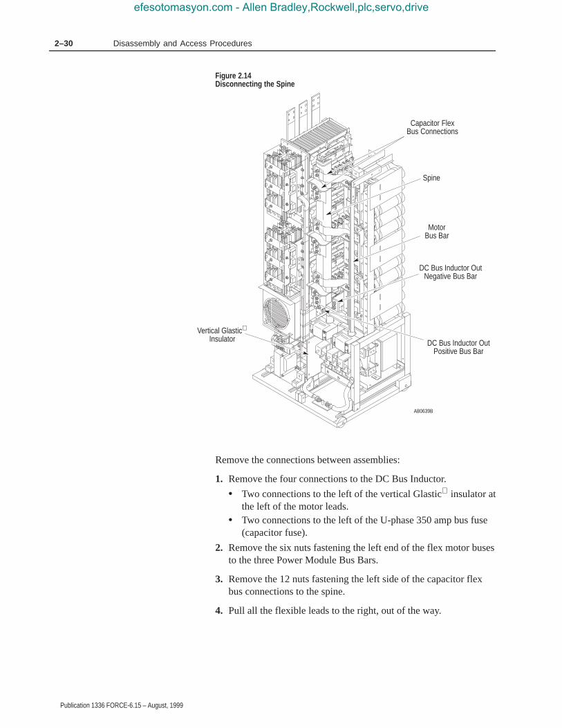
2–30 Disassembly and Access Procedures
Publication 1336 FORCE-6.15 – August, 1999
Figure 2.14Disconnecting the Spine
AB0639B
Capacitor FlexBus Connections
Spine
MotorBus Bar
DC Bus Inductor OutNegative Bus Bar
DC Bus Inductor OutPositive Bus Bar
Vertical Glastic
Insulator
Remove the connections between assemblies:
1. Remove the four connections to the DC Bus Inductor.
• Two connections to the left of the vertical Glastic insulator atthe left of the motor leads.
• Two connections to the left of the U-phase 350 amp bus fuse(capacitor fuse).
2. Remove the six nuts fastening the left end of the flex motor busesto the three Power Module Bus Bars.
3. Remove the 12 nuts fastening the left side of the capacitor flexbus connections to the spine.
4. Pull all the flexible leads to the right, out of the way.
efesotomasyon.com - Allen Bradley,Rockwell,plc,servo,drive

2–31Disassembly and Access Procedures
Publication 1336 FORCE-6.15 – August, 1999
Figure 2.15Removing the Spine
AB0680A
Capacitor FlexBus Connections
Spine
MotorBus Bar
DC Bus Inductor OutNegative Bus Bar
DC Bus Inductor OutPositive Bus Bar
Vertical Glastic
Insulator
5. Remove the spine.
• Push the spine carefully to the right.• Lift it out of the drive without forcing it.
6. Remove the six Gate Driver connectors from the Power ModuleGate Interface Boards. Pinch the sides of the connector bodywhile pulling back.
7. Disconnect any remaining wiring between the Inverter HousingAssembly and the Capacitor Bank Assembly.
8. Disconnect the Inverter Housing Assembly ground cable from theground plate at the bottom of the main assembly.
9. Remove the wheel chocks at the bottom of the Inverter HousingAssembly.
10.Pull the assembly onto a platform. Refer to Figure 2.16 forrecommendations. Use the handle attached to the Fan 2 housing.
efesotomasyon.com - Allen Bradley,Rockwell,plc,servo,drive

2–32 Disassembly and Access Procedures
Publication 1336 FORCE-6.15 – August, 1999
!ATTENTION: Hazard of tipping and severe injuryexists. This process requires two people. The platformmust be able to support 909 kg (2,000 lbs).
Figure 2.16Service Platform
AB0681A
30″25″
Height tosuit
installation
Stop Block
Fan 2 Handle
efesotomasyon.com - Allen Bradley,Rockwell,plc,servo,drive

2–33Disassembly and Access Procedures
Publication 1336 FORCE-6.15 – August, 1999
Installation
Install the Inverter Housing Assembly in reverse order of removal.
Important: When pushing the Inverter Housing Assembly into thedrive, you may need to have someone tip the unitslightly to the left or right to center it between theguides at the back of the Enclosure. Adjust the anglebrackets at the ends of the T-bar crossbar.
!ATTENTION: Replace all guards before applyingpower to the drive. Failure to replace guards may resultin death or serious injury.
efesotomasyon.com - Allen Bradley,Rockwell,plc,servo,drive

2–34 Disassembly and Access Procedures
Publication 1336 FORCE-6.15 – August, 1999
Removing the PC Board Mounting Frame
The PC Board Mounting Frame must be removed to pull theCapacitor Bank Assembly from the drive.
Figure 2.17PC Board Mounting Frame
AB0640A
PC BoardMountingFrame
!ATTENTION: Disconnect and lock out power fromthe drive before disassembling the drive. Failure todisconnect power may result in death or serious injury.Verify bus voltage by measuring the voltage betweenthe Negative Capacitor Bus and both ends of all three350 amp fuses. An open fuse does not show voltageacross both ends of the fuse. Failure to measure voltageat both ends of the fuses may result in death or seriousinjury. Refer to Figure 2.5. Do not attempt to service thedrive until the bus voltage has discharged to zero volts.
efesotomasyon.com - Allen Bradley,Rockwell,plc,servo,drive

2–35Disassembly and Access Procedures
Publication 1336 FORCE-6.15 – August, 1999
!ATTENTION: Wear a wrist-type grounding strapwhen servicing 1336 FORCE Drives. Failure toprotect drive components against ESD may damagedrive components. Refer to Electrostatic DischargePrecautions in Chapter 2 – Disassembly and AccessProcedures.
Important: Before you remove connections and wires from thedrive components, mark the connections and wires tocorrespond with their component connections andterminals to prevent incorrect wiring during assembly.
Removal
1. Remove power from the drive.
2. Open the PC Board Mounting Frame. Refer to Opening the DriveEnclosure in this chapter.
3. Check for zero volts between +DC and –DC. Refer to Figure 2.5.
4. Check for the absence of control voltage at:
• TB20 and TB21 on drives using a PLC Comm Adapter Board• TB5, TB6, and TB7 on drives using a Standard Adapter Board
5. Disconnect any wires connecting the PC Board Mounting Framewith either main assembly.
6. Open the PC Board Mounting Frame all the way to the right.
7. Lift the frame straight up to remove it from the hinges.
Installation
Install the PC Board Mounting Frame in reverse order of removal.
!ATTENTION: Replace all guards before applyingpower to the drive. Failure to replace guards may resultin death or serious injury.
efesotomasyon.com - Allen Bradley,Rockwell,plc,servo,drive

2–36 Disassembly and Access Procedures
Publication 1336 FORCE-6.15 – August, 1999
Access to the Capacitor Bank Assembly
Figure 2.18Capacitor Bank Assembly
AB0641B
CapacitorMounting Bolt
T-Bar
Motor CableTerminal Strips
Capacitor BankAssembly Ground Cable
Inverter HousingAssembly Ground Cable
!ATTENTION: Disconnect and lock out power fromthe drive before disassembling the drive. Failure todisconnect power may result in death or serious injury.Verify bus voltage by measuring the voltage betweenthe Negative Capacitor Bus and both ends of all three350 amp fuses. An open fuse does not show voltageacross both ends of the fuse. Failure to measure voltageat both ends of the fuses may result in death or seriousinjury. Refer to Figure 2.5. Do not attempt to service thedrive until the bus voltage has discharged to zero volts.
efesotomasyon.com - Allen Bradley,Rockwell,plc,servo,drive

2–37Disassembly and Access Procedures
Publication 1336 FORCE-6.15 – August, 1999
!ATTENTION: Wear a wrist-type grounding strapwhen servicing 1336 FORCE Drives. Failure to protectdrive components against ESD may damage drivecomponents. Refer to Electrostatic DischargePrecautions at the beginning of this chapter.
Important: Before you remove connections and wires from thedrive components, mark the connections and wires tocorrespond with their component connections andterminals to prevent incorrect wiring during assembly.
Removal
!ATTENTION: To remove either the InverterHousing Assembly or the Capacitor Bank Assemblysafely requires two persons. Attempting to removeeither assembly by yourself may result in death orserious injury.
!ATTENTION: Do not remove both the InverterHousing and the Capacitor Bank assemblies at thesame time.
Access the drive:
1. Remove power from the drive.
2. Open the PC Board Mounting Frame. Refer to Opening the DriveEnclosure in this chapter.
3. Check for zero volts between +DC and –DC. Refer to Figure 2.5.
4. Check for the absence of control voltage at:
• TB20 and TB21 on drives using a PLC Comm Adapter Board• TB5, TB6, and TB7 on drives using a Standard Adapter Board
5. Remove the motor cable connections from the terminal strips atthe bottom right of the drive.
6. Remove the PC Board Mounting Frame. Refer to Removing thePC Board Mounting Frame in this chapter.
Remove the T-Bar:
Important: Refer to Figure 2.13.
1. Release the locking nut between the inverter housing and the leftside of the T-bar.
2. Remove the T-bar mounting bolt at the bottom of the upright.
3. Remove the bolts fastening each end of the crossbar.
efesotomasyon.com - Allen Bradley,Rockwell,plc,servo,drive

2–38 Disassembly and Access Procedures
Publication 1336 FORCE-6.15 – August, 1999
4. Release the snapper pin at the top of the upright.
Remove the connections between assemblies:
Important: Refer to Figure 2.14.
1. Remove the four connections to the DC Bus Inductor.
• Two connections to the left of the vertical Glastic insulator atthe left of the motor leads.
• Two connections to the left of the U-phase 350 amp bus fuse(capacitor fuse).
2. Remove the six nuts fastening the left end of the motor flex busesto the three Power Module Bus Bars.
3. Remove the 12 nuts fastening the left side of the capacitor flexbus connections to the spine.
4. Pull all the flexible leads to the right, out of the way.
5. Remove the spine.
• Push the spine carefully to the right.• Lift it out of the drive without forcing it.
Access the Capacitor Bank Assembly:
1. Disconnect the Inverter Housing Assembly ground cable from theground plate at the bottom of the main frame.
2. Disconnect the Capacitor Bank Assembly ground cable.
3. Disconnect any ground wires that obstruct removal of the assembly.
4. Remove the capacitor mounting bolt at the top center of thecapacitor frame.
5. Remove the wheel chocks at the bottom of the Capacitor BankAssembly.
6. Pull the assembly onto a platform. Refer to Figure 2.16.
!ATTENTION: Hazard of tipping and severe injuryexists. This process requires two people. The platformmust be able to support 909 kg (2,000 lbs).
Installation
Install the Capacitor Bank Assembly in reverse order of removal.
Important: Guide the unit into place so that it mates with thelock-down bolt at the top of the capacitor frame. Adjustthe angle brackets at the ends of the T-bar crossbar.
efesotomasyon.com - Allen Bradley,Rockwell,plc,servo,drive

2–39Disassembly and Access Procedures
Publication 1336 FORCE-6.15 – August, 1999
!ATTENTION: Replace all guards before applyingpower to the drive. Failure to replace guards may resultin death or serious injury.
Removing a Power Module Snubber Board
The Power Module Snubber Boards are located on the Inverter HeatSink assembly.
Figure 2.19Power Module Snubber Board
AB0762A
PowerModuleSnubberBoard
Screw(8)
efesotomasyon.com - Allen Bradley,Rockwell,plc,servo,drive

2–40 Disassembly and Access Procedures
Publication 1336 FORCE-6.15 – August, 1999
Removal
!ATTENTION: Disconnect and lock out power fromthe drive before disassembling the drive. Failure todisconnect power may result in death or serious injury.Verify bus voltage by measuring the voltage betweenthe Negative Capacitor Bus and both ends of all three350 amp fuses. An open fuse does not show voltageacross both ends of the fuse. Failure to measure voltageat both ends of the fuses may result in death or seriousinjury. Refer to Figure 2.5. Do not attempt to service thedrive until the bus voltage has discharged to zero volts.
!ATTENTION: Hazard of electric shock exists. Up to1,600 VDC will be on Power Module Snubber BoardConnector J1 if the Snubber Resistor is open. Measurefor zero VDC from Snubber Board terminal TP3 toplus (+) bus before removing connector J1. Use aresistor greater than 1 ohm and less than 100 ohm,rated for 25 watts minimum, between pins 1 and 2 ofconnector J1 to discharge any voltage.
!ATTENTION: Wear a wrist-type grounding strapwhen servicing 1336 FORCE Drives. Failure to protectdrive components against ESD may damage drivecomponents. Refer to Electrostatic DischargePrecautions at the beginning of this chapter.
Important: Before you remove connections and wires from thedrive components, mark the connections and wires tocorrespond with their component connections andterminals to prevent incorrect wiring during assembly.
1. Remove power from the drive.
2. Open the PC Board Mounting Frame. Refer to Opening the DriveEnclosure in this chapter.
3. Check for zero volts between +DC and –DC. Refer to Figure 2.5.
4. Check for the absence of control voltage at:
• TB20 and TB21 on drives using a PLC Comm Adapter Board• TB5, TB6, and TB7 on drives using a Standard Adapter Board
5. Access the Inverter Housing Assembly. Refer to Chapter 2 –Disassembly and Access Procedures, Access to the InverterHousing Assembly.
efesotomasyon.com - Allen Bradley,Rockwell,plc,servo,drive

2–41Disassembly and Access Procedures
Publication 1336 FORCE-6.15 – August, 1999
6. Remove the snubber resistor J1 and J2 connections from thesnubber board.
7. Remove the screws fastening the Power Module Snubber Boardto the snubber bus bars.
Installation
!ATTENTION: Do not substitute longer or shorterhardware when fastening the Power Modulecomponents to the Power Modules. Use the same sizefastener to fasten the components as was originallyused. Using different fastener lengths will damage thePower Modules.
Install the Power Module Snubber Board in reverse order ofremoval. Refer to Table 2.A – Fastener Torque Specifications.
!ATTENTION: Replace all guards before applyingpower to the drive. Failure to replace guards may resultin death or serious injury.
efesotomasyon.com - Allen Bradley,Rockwell,plc,servo,drive

2–42 Disassembly and Access Procedures
Publication 1336 FORCE-6.15 – August, 1999
Removing an Input Rectifier Snubber Board
The Input Rectifier Snubber Boards are located on the InverterHousing Assembly, under the Guard, between the heat sinks and thevertical bus.
Figure 2.20Input Rectifier Snubber Board
AB0629A
Input RectifierSnubber Board
Guard
SCRs andHeat Sinks
efesotomasyon.com - Allen Bradley,Rockwell,plc,servo,drive

2–43Disassembly and Access Procedures
Publication 1336 FORCE-6.15 – August, 1999
Removal
!ATTENTION: Disconnect and lock out power fromthe drive before disassembling the drive. Failure todisconnect power may result in death or serious injury.Verify bus voltage by measuring the voltage betweenthe Negative Capacitor Bus and both ends of all three350 amp fuses. An open fuse does not show voltageacross both ends of the fuse. Failure to measure voltageat both ends of the fuses may result in death or seriousinjury. Refer to Figure 2.5. Do not attempt to service thedrive until the bus voltage has discharged to zero volts.
!ATTENTION: Wear a wrist-type grounding strapwhen servicing 1336 FORCE Drives. Failure to protectdrive components against ESD may damage drivecomponents. Refer to Electrostatic DischargePrecautions at the beginning of this chapter.
Important: Before you remove connections and wires from thedrive components, mark the connections and wires tocorrespond with their component connections andterminals to prevent incorrect wiring during assembly.
1. Remove power from the drive.
2. Open the PC Board Mounting Frame. Refer to Opening the DriveEnclosure in this chapter.
3. Check for zero volts between +DC and –DC. Refer to Figure 2.5.
4. Check for the absence of control voltage at:
• TB20 and TB21 on drives using a PLC Comm Adapter Board• TB5, TB6, and TB7 on drives using a Standard Adapter Board
5. Access the Inverter Housing Assembly. Refer to Chapter 2 –Disassembly and Access Procedures, Access to the InverterHousing Assembly.
6. Remove the plastic guard by removing the screws fastening theleft side of the guard to the SCR-heat sink assembly.
7. Remove the screws fastening the Input Rectifier Snubber Boardto the AC and DC snubber buses.
efesotomasyon.com - Allen Bradley,Rockwell,plc,servo,drive

2–44 Disassembly and Access Procedures
Publication 1336 FORCE-6.15 – August, 1999
Installation
Install the Input Rectifier Snubber Board in reverse order of removal.Refer to Table 2.A – Fastener Torque Specifications.
!ATTENTION: Replace all guards before applyingpower to the drive. Failure to replace guards may resultin death or serious injury.
efesotomasyon.com - Allen Bradley,Rockwell,plc,servo,drive

Chapter 3
Publication 1336 FORCE-6.15 – August, 1999
Component Test Procedures
The following tests help you troubleshoot B300 – B600, C300 –C600, and BX250 drives.
In some cases, different tests troubleshoot components of the samename.
These similar tests vary according to the rating of the drive beingtested. Verify that the rating on the drive matches the rating for thetest you are performing.
The part replacement procedures in this chapter assume that the driveyou are servicing either has no enclosure or that the enclosure isopen. For more information on opening the Drive Enclosure, refer toChapter 2 – Disassembly and Access Procedures, Opening the DriveEnclosure.
!ATTENTION: Some printed circuit boards and drivecomponents may contain hazardous voltage levels.Remove and lock out power before you disconnect orreconnect wires, and before you remove or replacefuses and circuit boards. Verify bus voltage bymeasuring the voltage between the Negative CapacitorBus and both ends of all three 350 amp fuses. An openfuse does not show voltage across both ends of thefuse. Failure to measure voltage at both ends of thefuses may result in death or serious injury. Refer toFigure 2.5. Do not attempt to service the drive until thebus voltage has discharged to zero volts.
!ATTENTION: Servicing energized industrial controlequipment can be hazardous. Electrical shock, burns,or unintentional actuation of controlled industrialequipment may cause death or serious injury. Followthe safety-related practices of NFPA 70E, ElectricalSafety for Employee Workplaces, when working on ornear energized equipment. Do not work alone onenergized equipment.
Chapter Objectives
Component TestOverview
efesotomasyon.com - Allen Bradley,Rockwell,plc,servo,drive

3–2 Component Test Procedures
Publication 1336 FORCE-6.15 – August, 1999
!ATTENTION: This assembly contains parts andsub-assemblies that are sensitive to electrostaticdischarge. Static control precautions are required whenservicing this assembly. Component damage may resultif you ignore electrostatic discharge control procedures.If you are not familiar with static control procedures,reference Allen-Bradley Publication 8000-4.5.2,Guarding Against Electrostatic Discharge, or any otherapplicable ESD protection handbook.
Electrostatic discharge generated by static electricity can damage thecomplimentary metallic oxide semiconductor devices on variousdrive boards. It is recommended that you perform these proceduresto guard against this type of damage when circuit boards areremoved or installed:
• Wear a wrist-type grounding strap that is grounded to the chassis.
• Attach the wrist strap before removing the new circuit board fromthe conductive packet.
• Remove boards from the drive and immediately insert them intotheir conductive packets.
Tools
For a list of tools required, tightening sequences, and fastener torquespecifications, refer to Chapter 2 – Disassembly and AccessProcedures, Fastener Torque Specifications.
Electrostatic DischargePrecautions
efesotomasyon.com - Allen Bradley,Rockwell,plc,servo,drive

3–3Component Test Procedures
Publication 1336 FORCE-6.15 – August, 1999
The Gate Driver Board is located behind the Main Control Board, onthe PC Board Mounting Frame. If power modules were replaced,replace the Gate Driver Board. If a new Gate Driver Board is notavailable, test the old board using the following procedure.
Figure 3.1Gate Driver Board Test
AB0604B
F3
VR2VR3VR5
VR6
VR1
VR4F1
Gate DriverBoard
D78
D71
D72
D65
D66
D10
!ATTENTION: Disconnect and lock out power fromthe drive before disassembling the drive. Failure todisconnect power may result in death or serious injury.Verify bus voltage by measuring the voltage betweenthe Negative Capacitor Bus and both ends of all three350 amp fuses. An open fuse does not show voltageacross both ends of the fuse. Failure to measure voltageat both ends of the fuses may result in death or seriousinjury. Refer to Figure 2.5. Do not attempt to service thedrive until the bus voltage has discharged to zero volts.
Test 1Testing the Gate Driver Board
efesotomasyon.com - Allen Bradley,Rockwell,plc,servo,drive

3–4 Component Test Procedures
Publication 1336 FORCE-6.15 – August, 1999
!ATTENTION: Wear a wrist-type grounding strapwhen servicing 1336 FORCE Drives. Failure to protectdrive components against ESD may damage drivecomponents. Refer to Electrostatic DischargePrecautions in Chapter 2 – Disassembly and AccessProcedures.
Important: Before you remove connections and wires from thedrive components, mark the connections and wires tocorrespond with their component connections andterminals to prevent incorrect wiring during assembly.
1. Remove power from the drive.
2. Open the PC Board Mounting Frame. Refer to Opening the DriveEnclosure in Chapter 2.
3. Check for zero volts between +DC and –DC. Refer to Figure 2.5.
4. Check for the absence of control voltage at:
• TB20 and TB21 on drives using a PLC Comm Adapter Board• TB5, TB6, and TB7 on drives using a Standard Adapter Board
5. Remove the Control Board/Adapter Mounting Plate. Refer toChapter 2 – Disassembly and Access Procedures, Removing theControl Board/Adapter Mounting Plate.
6. Test Gate Driver Board fuses F1 and F3 for an open condition.Replace the Gate Driver Board if either fuse shows an opencondition.
7. Set your meter to test diodes.
8. Test VR1 – VR6. The following table shows meter connections atthe components and ideal meter readings for those connections.Refer to the previous illustration for component locations.
efesotomasyon.com - Allen Bradley,Rockwell,plc,servo,drive

3–5Component Test Procedures
Publication 1336 FORCE-6.15 – August, 1999
Table 3.AGate Driver Board Test
ComponentMeter (+)
LeadMeter (–)
LeadNominal Meter
Reading*
VR1 – VR6+ – 1.06
VR1 – VR6– + 1.8
Note: Typical malfunction is shorted in both directions.
* Meter Used: Fluke Model 87, set to “Diode” range.
9. Replace the Gate Driver Board if your readings do not match thetable readings. Refer to Chapter 2 – Disassembly and AccessProcedures, Removing the Gate Driver Board.
10.Check all six reverse-bias Zener diodes: D10, D66, D65, D78,D71, and D72. The following table shows meter connections atthe components and ideal meter readings for those connections.Refer to the previous illustration for component locations.
Table 3.BZener Diode Test
ComponentMeter
(+) LeadMeter
(–) LeadNominal Meter
Reading
D78 +–
–+
less than 1open
D71 +–
–+
less than 1open
D72 +–
–+
less than 1open
D65 +–
–+
less than 1open
D66 +–
–+
less than 1open
D10 +–
–+
less than 1open
11.Replace the Gate Driver Board if your readings do not match thetable, or if any diode is shorted or open in both directions. Refer toChapter 2 – Disassembly and Access Procedures, Removing theGate Driver Board.
12.Assemble the drive in reverse order of disassembly.
efesotomasyon.com - Allen Bradley,Rockwell,plc,servo,drive

3–6 Component Test Procedures
Publication 1336 FORCE-6.15 – August, 1999
!ATTENTION: When removing the entire wireharness connecting Gate Driver Board connector J9 toPrecharge Board connector J3, align the wires on theharness terminals with the pins on the boardconnectors. Incorrect harness connection may result infaulty drive operation and may damage the equipment.
!ATTENTION: Replace all guards before applyingpower to the drive. Failure to replace guards may resultin death or serious injury.
efesotomasyon.com - Allen Bradley,Rockwell,plc,servo,drive

3–7Component Test Procedures
Publication 1336 FORCE-6.15 – August, 1999
If Power Modules have been replaced, you must test the PowerModule Snubber Board, the Precharge Board, and the Gate DriverBoard.
Figure 3.2Precharge Board Test
AB0605A
PrechargeBoard F3
F2F1
!ATTENTION: Disconnect and lock out power fromthe drive before disassembling the drive. Failure todisconnect power may result in death or serious injury.Verify bus voltage by measuring the voltage betweenthe Negative Capacitor Bus and both ends of all three350 amp fuses. An open fuse does not show voltageacross both ends of the fuse. Failure to measure voltageat both ends of the fuses may result in death or seriousinjury. Refer to Figure 2.5. Do not attempt to service thedrive until the bus voltage has discharged to zero volts.
Test 2Testing thePrecharge Board
efesotomasyon.com - Allen Bradley,Rockwell,plc,servo,drive

3–8 Component Test Procedures
Publication 1336 FORCE-6.15 – August, 1999
!ATTENTION: Wear a wrist-type grounding strapwhen servicing 1336 FORCE Drives. Failure to protectdrive components against ESD may damage drivecomponents. Refer to Electrostatic Discharge Precautionsin Chapter 2 – Disassembly and Access Procedures.
Important: Before you remove connections and wires from thedrive components, mark the connections and wires tocorrespond with their component connections andterminals to prevent incorrect wiring during assembly.
1. Remove power from the drive.
2. Open the PC Board Mounting Frame. Refer to Opening the DriveEnclosure in Chapter 2.
3. Check for zero volts between +DC and –DC. Refer to Figure 2.5.
4. Check for the absence of control voltage at:
• TB20 and TB21 on drives using a PLC Comm Adapter Board• TB5, TB6, and TB7 on drives using a Standard Adapter Board
5. Set your meter to test resistance.
6. Test Precharge Board fuses F1, F2, and F3 for open conditions.
7. Replace the Precharge Board if any fuse shows an opencondition. Refer to Chapter 2 – Disassembly and AccessProcedures, Removing the Precharge Board.
!ATTENTION: Replace all guards before applyingpower to the drive. Failure to replace guards may resultin death or serious injury.
efesotomasyon.com - Allen Bradley,Rockwell,plc,servo,drive

3–9Component Test Procedures
Publication 1336 FORCE-6.15 – August, 1999
The Power Modules are located on three heat sinks in the InverterHousing Assembly. If Power Modules have been replaced, you mustcheck the corresponding Power Module Snubber Board and SnubberResistor in addition to replacing the Gate Driver Board. Refer toChapter 2 – Disassembly and Access Procedures, Removing a PowerModule Snubber Board.
Figure 3.3Power Module Test
AB0606A
Gate (G)
Collector (C)Emitter (E)
Emitter PowerTabs (E)
Collector PowerTabs (C)
Test 3Testing thePower Modules
efesotomasyon.com - Allen Bradley,Rockwell,plc,servo,drive

3–10 Component Test Procedures
Publication 1336 FORCE-6.15 – August, 1999
!ATTENTION: Disconnect and lock out power fromthe drive before disassembling the drive. Failure todisconnect power may result in death or serious injury.Verify bus voltage by measuring the voltage betweenthe Negative Capacitor Bus and both ends of all three350 amp fuses. An open fuse does not show voltageacross both ends of the fuse. Failure to measure voltageat both ends of the fuses may result in death or seriousinjury. Refer to Figure 2.5. Do not attempt to service thedrive until the bus voltage has discharged to zero volts.
!ATTENTION: Wear a wrist-type grounding strapwhen servicing 1336 FORCE Drives. Failure to protectdrive components against ESD may damage drivecomponents. Refer to Electrostatic DischargePrecautions in Chapter 2 – Disassembly and AccessProcedures.
Important: Before you remove connections and wires from thedrive components, mark the connections and wires tocorrespond with their component connections andterminals to prevent incorrect wiring during assembly.
1. Remove power from the drive.
2. Open the PC Board Mounting Frame. Refer to Opening the DriveEnclosure in Chapter 2.
3. Check for zero volts between +DC and –DC. Refer to Figure 2.5.
4. Check for the absence of control voltage at:
• TB20 and TB21 on drives using a PLC Comm Adapter Board• TB5, TB6, and TB7 on drives using a Standard Adapter Board
5. Access the Inverter Housing Assembly. Refer to Chapter 2 –Disassembly and Access Procedures, Access to the InverterHousing Assembly.
6. Remove the Power Module Snubber Board. Refer to Chapter 2 –Disassembly and Access Procedures, Removing a Power ModuleSnubber Board.
7. Set your meter to test diodes.
8. Test the Power Modules. The following table shows meterconnections and ideal meter readings for those connections. Referto the former illustration for meter connection locations.
efesotomasyon.com - Allen Bradley,Rockwell,plc,servo,drive
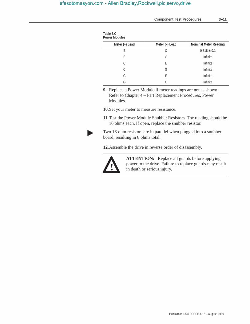
3–11Component Test Procedures
Publication 1336 FORCE-6.15 – August, 1999
Table 3.CPower Modules
Meter (+) Lead Meter (–) Lead Nominal Meter Reading
E C 0.318 ± 0.1
E G Infinite
C E Infinite
C G Infinite
G E Infinite
G C Infinite
9. Replace a Power Module if meter readings are not as shown.Refer to Chapter 4 – Part Replacement Procedures, PowerModules.
10.Set your meter to measure resistance.
11.Test the Power Module Snubber Resistors. The reading should be16 ohms each. If open, replace the snubber resistor.
Two 16-ohm resistors are in parallel when plugged into a snubberboard, resulting in 8 ohms total.
12.Assemble the drive in reverse order of disassembly.
!ATTENTION: Replace all guards before applyingpower to the drive. Failure to replace guards may resultin death or serious injury.
�
efesotomasyon.com - Allen Bradley,Rockwell,plc,servo,drive
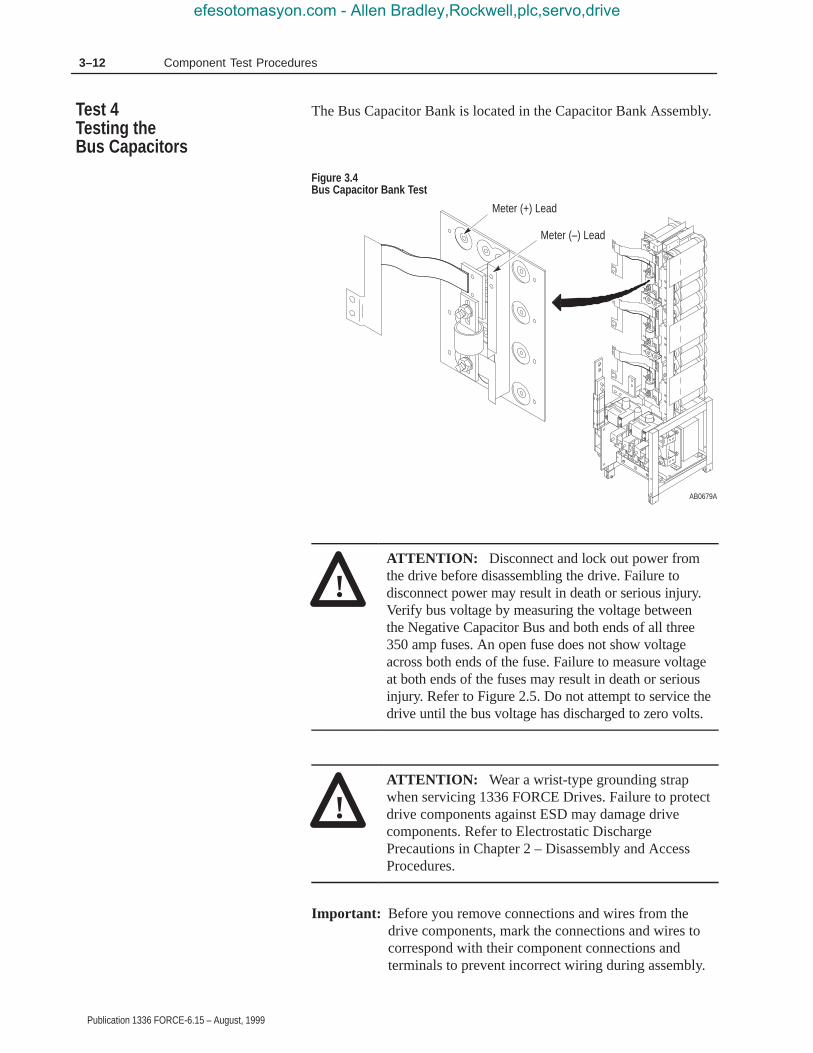
3–12 Component Test Procedures
Publication 1336 FORCE-6.15 – August, 1999
The Bus Capacitor Bank is located in the Capacitor Bank Assembly.
Figure 3.4Bus Capacitor Bank Test
AB0679A
Meter (–) Lead
Meter (+) Lead
!ATTENTION: Disconnect and lock out power fromthe drive before disassembling the drive. Failure todisconnect power may result in death or serious injury.Verify bus voltage by measuring the voltage betweenthe Negative Capacitor Bus and both ends of all three350 amp fuses. An open fuse does not show voltageacross both ends of the fuse. Failure to measure voltageat both ends of the fuses may result in death or seriousinjury. Refer to Figure 2.5. Do not attempt to service thedrive until the bus voltage has discharged to zero volts.
!ATTENTION: Wear a wrist-type grounding strapwhen servicing 1336 FORCE Drives. Failure to protectdrive components against ESD may damage drivecomponents. Refer to Electrostatic DischargePrecautions in Chapter 2 – Disassembly and AccessProcedures.
Important: Before you remove connections and wires from thedrive components, mark the connections and wires tocorrespond with their component connections andterminals to prevent incorrect wiring during assembly.
Test 4Testing the Bus Capacitors
efesotomasyon.com - Allen Bradley,Rockwell,plc,servo,drive

3–13Component Test Procedures
Publication 1336 FORCE-6.15 – August, 1999
Access the drive:
1. Remove power from the drive.
2. Open the PC Board Mounting Frame. Refer to Opening the DriveEnclosure in Chapter 2.
3. Check for zero volts between +DC and –DC. Refer to Figure 3.4.
4. Check for the absence of control voltage at:
• TB20 and TB21 on drives using a PLC Comm Adapter Board• TB5, TB6, and TB7 on drives using a Standard Adapter Board
Test the Capacitors:
1. Set your meter to test voltage.
2. Connect the negative lead of the meter to –DC and the positivelead to the capacitor terminal called out in Figure 3.4.
!ATTENTION: Servicing energized industrial controlequipment can be hazardous. Electrical shock, burns,or unintentional actuation of controlled industrialequipment may cause death or serious injury. Followthe safety-related practices of NFPA 70E, ElectricalSafety for Employee Workplaces, when working on ornear energized equipment. Do not work alone onenergized equipment.
3. Apply power AFTER the meter is connected, otherwise yourmeter will read zero volts.
Refer to Table 3.D for nominal meter readings.
Table 3.DCapacitor Test Meter Readings
Drive Series Input Volts Meter�
380 V 178 V
B 415 V 193 V
480 V 218 V
500 V 233 V
C 575 V 267 V
600 V 283 V
� If the capacitors are normal, the meter reading should be one third the voltage across the totalcapacitor bank.
4. Using this procedure, test each of the three Capacitor Banksections. Table 3.E shows the correct voltage for the totalCapacitor Bank.
efesotomasyon.com - Allen Bradley,Rockwell,plc,servo,drive

3–14 Component Test Procedures
Publication 1336 FORCE-6.15 – August, 1999
Table 3.EBus Capacitor Bank Test
DriveRating
InputVolts
Meter Reading
B380415480
535V DC +/–10%580V DC +/–10%650V DC +/–10%
C500575600
700V DC +/–10%800V DC +/–10%850V DC +/–10%
5. If the voltage is out of tolerance, check the following:
• An open condition at an Input Rectifier.• A voltage drop due to DC Bus Inductor resistance.• A voltage drop between an Input Rectifier and the bus
capacitors due to loose or resistive wires or connections.• Precharge circuit problems.
6. If the above check does not reveal a problem, replace the BusCapacitor Bank and Load-Sharing Resistors. Refer to Chapter 4 –Part Replacement Procedures, Bus Capacitor Bank.
!ATTENTION: Replace all guards before applyingpower to the drive. Failure to replace guards may resultin death or serious injury.
efesotomasyon.com - Allen Bradley,Rockwell,plc,servo,drive

3–15Component Test Procedures
Publication 1336 FORCE-6.15 – August, 1999
The SCRs are located in the heat sinks on the Inverter HousingAssembly.
!ATTENTION: Disconnect and lock out power fromthe drive before disassembling the drive. Failure todisconnect power may result in death or serious injury.Verify bus voltage by measuring the voltage betweenthe Negative Capacitor Bus and both ends of all three350 amp fuses. An open fuse does not show voltageacross both ends of the fuse. Failure to measure voltageat both ends of the fuses may result in death or seriousinjury. Refer to Figure 2.5. Do not attempt to service thedrive until the bus voltage has discharged to zero volts.
!ATTENTION: Wear a wrist-type grounding strapwhen servicing 1336 FORCE Drives. Failure to protectdrive components against ESD may damage drivecomponents. Refer to Electrostatic DischargePrecautions in Chapter 2 – Disassembly and AccessProcedures.
Important: Before you remove connections and wires from thedrive components, mark the connections and wires tocorrespond with their component connections andterminals to prevent incorrect wiring during assembly.
Access the drive:
1. Remove power from the drive.
2. Open the PC Board Mounting Frame. Refer to Opening the DriveEnclosure in Chapter 2.
3. Check for zero volts between +DC and –DC. Refer to Figure 2.5.
4. Check for the absence of control voltage at:
• TB20 and TB21 on drives using a PLC Comm Adapter Board• TB5, TB6, and TB7 on drives using a Standard Adapter Board
Test the SCRs:
1. Set your meter to test resistance.
2. Measure resistance from AC inputs L1, L2, and L3 to +DC. Referto Table 3.F.
3. Measure between each pair of gate and cathode terminals on thePrecharge Board. Refer to Table 3.G.
Test 5Testing the SCRs
efesotomasyon.com - Allen Bradley,Rockwell,plc,servo,drive

3–16 Component Test Procedures
Publication 1336 FORCE-6.15 – August, 1999
The following tables show meter connections and ideal meterreadings for those connections. Refer to the schematic in this manualfor more information.
Table 3.FSCR Test at AC Input
Meter (+) Lead Meter (–) Lead Nominal Meter Reading
L1
L2 +DC
L3Infinite
L1Infinite
L2 –DC
L3
Table 3.GSCR Test at Precharge Board
SCR Meter (+) Lead Meter (–) Lead Nominal MeterReading
J1 Connector
SCR1R1G R1K 10
SCR1R1K R1G 10
SCR3S1G S1K 10
SCR3S1G S1G 10
SCR5T1G T1K 10
SCR5T1K T1G 10
J2 Connector
SCR4R2G R2K 10
SCR4R2K R2G 10
SCR6S2G S2K 10
SCR6S2K S2G 10
SCR2T2G T2K 10
SCR2T2K T2G 10
4. Replace the SCR if any meter readings are not as shown. Refer toChapter 4 – Part Replacement Procedures, SCRs.
5. If an SCR requires replacement, check the Power Modules fordamage. Refer to Testing the Power Modules in this chapter.
!ATTENTION: Replace all guards before applyingpower to the drive. Failure to replace guards may resultin death or serious injury.
efesotomasyon.com - Allen Bradley,Rockwell,plc,servo,drive
Chapter 4
Publication 1336 FORCE-6.15 – August, 1999
Part Replacement Procedures
This chapter describes procedures required to replace drivecomponents. This chapter references Chapter 2 – Disassembly andAccess Procedures for basic drive component access.
The part replacement procedures in this chapter assume that the driveyou are servicing either has no enclosure or that the enclosure isopen. For more information on opening the Drive Enclosure, refer toChapter 2 – Disassembly and Access Procedures, Opening the DriveEnclosure.
!ATTENTION: Some printed circuit boards and drivecomponents may contain hazardous voltage levels.Remove power before you disconnect or reconnectwires, and before you remove or replace fuses andcircuit boards. Verify bus voltage by measuring thevoltage between between the Negative Capacitor Busand both ends of all three 350 amp fuses. An open fusedoes not show voltage across both ends of the fuse.Failure to measure voltage at both ends of the fuses mayresult in death or serious injury. Refer to Figure 2.5. Donot attempt to service the drive until the bus voltage hasdischarged to zero volts.
Chapter Objective
Part ReplacementOverview
Safety Precautions
efesotomasyon.com - Allen Bradley,Rockwell,plc,servo,drive

4–2 Part Replacement Procedures
Publication 1336 FORCE-6.15 – August, 1999
!ATTENTION: This assembly contains parts andsub-assemblies that are sensitive to electrostaticdischarge. Static control precautions are required whenservicing this assembly. Component damage may resultif you ignore electrostatic discharge control procedures.If you are not familiar with static control procedures,reference Allen-Bradley Publication 8000–4.5.2,Guarding Against Electrostatic Discharge, or any otherapplicable ESD protection handbook.
Electrostatic discharge generated by static electricity can damage thecomplimentary metallic oxide semiconductor devices on variousdrive boards. It is recommended that you perform these proceduresto guard against this type of damage when circuit boards areremoved or installed:
• Wear a wrist-type grounding strap that is grounded to the chassis.
• Attach the wrist strap before removing the new circuit board fromthe conductive packet.
• Remove boards from the drive and immediately insert them intotheir conductive packets.
For a list of tools required, tightening sequences, and fastener torquespecifications, refer to Chapter 2 – Disassembly and AccessProcedures, Fastener Torque Specifications.
Electrostatic DischargePrecautions
efesotomasyon.com - Allen Bradley,Rockwell,plc,servo,drive

4–3Part Replacement Procedures
Publication 1336 FORCE-6.15 – August, 1999
This section explains in detail how to replace the following drivecomponents:
• Bus Capacitor Bank
• Thermistor
• Power Modules
• Power Module Snubber Resistor
• SCRs
• Fans and Transformer Assembly
• DC Bus Inductor
• Ground Sense CT
• Bus Fuses
• LEMs
• MOV Surge Suppressor
• Thermal Switch
For Gate Driver Board, Precharge Board, Main Control Board,Standard Adapter Board, PLC Comm Adapter Board, SnubberBoard, and Control Interface L-Option Board installation andremoval procedures, refer to Chapter 2.
Allen-Bradley Adjustable Frequency AC Drives are modular bydesign to enhance troubleshooting and spare parts replacement,thereby helping reduce production down-time.
The following illustration calls out the main components of a typicaldrive. Component designs vary slightly among the different driveratings, but component locations are identical.
Major ComponentReplacement
Detailed ProductIdentification
efesotomasyon.com - Allen Bradley,Rockwell,plc,servo,drive

4–4 Part Replacement Procedures
Publication 1336 FORCE-6.15 – August, 1999
Figure 4.1Main Drive Components
AB0707A
PowerModule
GroundSense CT
Input RectifierSnubber Board
Power ModuleBus Bar
Power ModuleGate Interface
Board
LEM
FanTransformer
FanCapacitor
DC BusInductor
MOV SurgeSuppressor
Bus FuseF1
Bus CapacitorBank
Control InterfaceL-Option Board
Main ControlBoard
PrechargeBoard
PrechargeBoard Fuses
Gate DriverBoard
Fuse F3
Fuse F1
Power ModuleSnubber Board
Thermistor
Power ModuleSnubber Resistor
Fan 1
Fan 2
ThermalSwitch
SCR
Load SharingResistor
PLC CommAdapter Board
StandardAdapter Board
Control Board/AdapterMounting Plate
efesotomasyon.com - Allen Bradley,Rockwell,plc,servo,drive

4–5Part Replacement Procedures
Publication 1336 FORCE-6.15 – August, 1999
Bus Capacitor Bank
The Bus Capacitor Bank is located in the Capacitor Bank Assembly.
Figure 4.2Bus Capacitor Bank
AB0608A
Bus CapacitorCap
Bus CapacitorHolder
CapacitorLaminated Bus Bar
Bus FuseF1
TerminalStrips
Motor BusBottom Support
CapacitorInsulator
BalancerPlate
MotorBuses
efesotomasyon.com - Allen Bradley,Rockwell,plc,servo,drive

4–6 Part Replacement Procedures
Publication 1336 FORCE-6.15 – August, 1999
Removal
!ATTENTION: Disconnect and lock out power fromthe drive before disassembling the drive. Failure todisconnect power may result in death or serious injury.Verify bus voltage by measuring the voltage betweenbetween the Negative Capacitor Bus and both ends of allthree 350 amp fuses. An open fuse does not show voltageacross both ends of the fuse. Failure to measure voltage atboth ends of the fuses may result in death or seriousinjury. Refer to Figure 2.5. Do not attempt to service thedrive until the bus voltage has discharged to zero volts.
!ATTENTION: Wear a wrist-type grounding strapwhen servicing 1336 FORCE Drives. Failure to protectdrive components against ESD may damage drivecomponents. Refer to Electrostatic DischargePrecautions at the beginning of this chapter.
Important: Before you remove connections and wires from drivecomponents, mark the connections and wires tocorrespond with their component connections andterminals to prevent incorrect wiring during assembly.
1. Remove power from the drive.
2. Open the PC Board Mounting Frame. Refer to Opening the DriveEnclosure in Chapter 2.
3. Check for zero volts between +DC and –DC. Refer to Figure 2.5.
4. Check for the absence of control voltage at:
• TB20 and TB21 on drives using a PLC Comm Adapter Board• TB5, TB6, and TB7 on drives using a Standard Adapter Board
5. Access the Capacitor Bank Assembly. Refer to Chapter 2 –Disassembly and Access Procedures, Access to the CapacitorBank Assembly.
Remove the Motor Buses:
1. Remove the screws fastening each motor bus to the top of itsTerminal Strip near the bottom of the Capacitor Bank Assembly.
2. Remove the screws fastening the motor buses to the Motor BusBottom Support.
3. Remove the motor buses.
Access the Capacitors:
1. Remove the screws fastening the wires from the Balancer Plateassembly to the capacitors.
2. Remove the screws, nuts, and washers fastening the CapacitorLaminated Bus Bar to the capacitors.
efesotomasyon.com - Allen Bradley,Rockwell,plc,servo,drive

4–7Part Replacement Procedures
Publication 1336 FORCE-6.15 – August, 1999
3. Remove the Capacitor Laminated Bus Bar and attachedcomponents.
4. Remove the plastic caps at the four corners of each capacitorinsulator.
5. Remove the capacitors from the drive.
Installation
1. Install the capacitor assembly in reverse order of removal. Referto Chapter 2 – Disassembly and Access Procedures, FastenerTorque Specifications.
Important: Position the notch and vent hole on the Bus Capacitorsto the top of the drive.
2. Connect the Load-Sharing Resistors to the Bus Capacitorsaccording to the following diagram. Refer to the schematicdiagrams in this manual for more information on componentconfigurations.
Figure 4.3Load-Sharing Resistor Connections to Bus Capacitors
R4 – R6
C13 – C24 C25 – C36
R7 – R9
C5
C9
–
CAP DETAIL575V
R3C10 C11 C12
C6 C7 C8R2
C1 C2 C3 C4R1
+ D3
F3
D2
F2
F1
D1
C41
C40
X
C1 C2 C3 C4
C8C7C6C5
R1
R2
CAP DETAIL460V
C9 – C16
R3 – R4
C17 – C24
R5 – R6
D1
D2
D3F2
F1
F3
+
–
C40
C41
X
efesotomasyon.com - Allen Bradley,Rockwell,plc,servo,drive

4–8 Part Replacement Procedures
Publication 1336 FORCE-6.15 – August, 1999
!ATTENTION: Capacitors not installed correctly willexplode or vent and may cause death or serious injury.Observe correct polarities.
!ATTENTION: Replace all guards before applyingpower to the drive. Failure to replace guards may resultin death or serious injury.
Thermistor
The Thermistor is located at the top of the heat sink in the InverterHousing Assembly.
Figure 4.4Thermistor
AB0627A
Thermistor
Connector to MainControl Board J1
efesotomasyon.com - Allen Bradley,Rockwell,plc,servo,drive

4–9Part Replacement Procedures
Publication 1336 FORCE-6.15 – August, 1999
Removal
!ATTENTION: Disconnect and lock out power fromthe drive before disassembling the drive. Failure todisconnect power may result in death or serious injury.Verify bus voltage by measuring the voltage betweenthe Negative Capacitor Bus and both ends of all three350 amp fuses. An open fuse does not show voltageacross both ends of the fuse. Failure to measure voltageat both ends of the fuses may result in death or seriousinjury. Refer to Figure 2.5. Do not attempt to service thedrive until the bus voltage has discharged to zero volts.
!ATTENTION: Hazard of electric shock exists. Up to1,600 VDC will be on Power Module Snubber BoardConnector J1 if the Snubber Resistor is open. Measurefor zero VDC from Snubber Board terminal TP3 toplus (+) bus before removing Connector J1. Use aresistor greater than 1 ohm and less than 100 ohm,rated for 25 watts minimum, between TP3 and plus (+)bus to discharge any voltage. Refer to Chapter 2 –Disassembly and Access Procedures, Removing aPower Module Snubber Board.
!ATTENTION: Wear a wrist-type grounding strapwhen servicing 1336 FORCE Drives. Failure to protectdrive components against ESD may damage drivecomponents. Refer to Electrostatic DischargePrecautions at the beginning of this chapter.
Important: Before you remove connections and wires from thedrive components, mark the connections and wires tocorrespond with their component connections andterminals to prevent incorrect wiring during assembly.
1. Remove power from the drive.
2. Open the PC Board Mounting Frame. Refer to Opening the DriveEnclosure in Chapter 2.
3. Check for zero volts between +DC and –DC. Refer to Figure 2.5.
4. Check for the absence of control voltage at:
• TB20 and TB21 on drives using a PLC Comm Adapter Board• TB5, TB6, and TB7 on drives using a Standard Adapter Board
efesotomasyon.com - Allen Bradley,Rockwell,plc,servo,drive

4–10 Part Replacement Procedures
Publication 1336 FORCE-6.15 – August, 1999
5. Disconnect Main Control Board Connector J1.
6. Remove the Thermistor.
Installation
Install the Thermistor in reverse order of removal. Refer to Chapter 2– Disassembly and Access Procedures, Fastener TorqueSpecifications.
!ATTENTION: Replace all guards before applyingpower to the drive. Failure to replace guards may resultin death or serious injury.
efesotomasyon.com - Allen Bradley,Rockwell,plc,servo,drive

4–11Part Replacement Procedures
Publication 1336 FORCE-6.15 – August, 1999
Power Modules
The Power Modules are located on the heat sink toward the back ofthe Inverter Housing Assembly. If one or more Power Modules isreplaced, you must check the Power Module Snubber Board, thePrecharge Board, and the Gate Driver Board.
Figure 4.5Power Modules
AB0609B
Power ModulePreform
Power Module GateInterface Board
Power ModuleBus Bar Snubber
Bus Bars
Insulator
efesotomasyon.com - Allen Bradley,Rockwell,plc,servo,drive

4–12 Part Replacement Procedures
Publication 1336 FORCE-6.15 – August, 1999
Removal
!ATTENTION: Disconnect and lock out power fromthe drive before disassembling the drive. Failure todisconnect power may result in death or serious injury.Verify bus voltage by measuring the voltage betweenthe Negative Capacitor Bus and both ends of all three350 amp fuses. An open fuse does not show voltageacross both ends of the fuse. Failure to measure voltageat both ends of the fuses may result in death or seriousinjury. Refer to Figure 2.5. Do not attempt to service thedrive until the bus voltage has discharged to zero volts.
!ATTENTION: Hazard of electric shock exists. Up to1,600 VDC will be on Power Module Snubber BoardConnector J1 if the Snubber Resistor is open. Measurefor zero VDC from Snubber Board terminal TP3 toplus (+) bus before removing connector J1. Use aresistor greater than 1 ohm and less than 100 ohm,rated for 25 watts minimum, between TP3 and plus (+)bus to discharge any voltage. Refer to Chapter 2 –Disassembly and Access Procedures, Removing aPower Module Snubber Board.
!ATTENTION: Wear a wrist-type grounding strapwhen servicing 1336 FORCE Drives. Failure to protectdrive components against ESD may damage drivecomponents. Refer to Electrostatic DischargePrecautions at the beginning of this chapter.
Important: Before you remove connections and wires from thedrive components, mark the connections and wires tocorrespond with their component connections andterminals to prevent incorrect wiring during assembly.
1. Remove power from the drive.
2. Open the PC Board Mounting Frame. Refer to Opening the DriveEnclosure in Chapter 2.
3. Check for zero volts between +DC and –DC. Refer to Figure 2.5.
4. Check for the absence of control voltage at:
• TB20 and TB21 on drives using a PLC Comm Adapter Board• TB5, TB6, and TB7 on drives using a Standard Adapter Board
efesotomasyon.com - Allen Bradley,Rockwell,plc,servo,drive

4–13Part Replacement Procedures
Publication 1336 FORCE-6.15 – August, 1999
5. Access the Inverter Housing Assembly. Refer to Chapter 2 –Disassembly and Access Procedures, Access to the InverterHousing Assembly.
6. Remove the screws fastening the positive and negative snubberbus bars to the Power Module Bus Bar.
7. Remove the screws fastening the Power Module Bus Bar to thePower Modules.
8. Carefully remove the bus bar. Do not damage the insulation.
9. Remove the screws fastening the Power Module Gate InterfaceBoards to the Power Modules.
10.Remove the Power Module Gate Interface Boards.
11.Remove the screws fastening the Power Module to the heat sink.Refer to Figure 2.3 in Chapter 2 – Disassembly and AccessProcedures. Follow the torque sequence, as illustrated, for bothremoval and installation.
Installation
1. Clean all surfaces between the Power Module and the heat sinkusing a soft, clean cloth.
2. Replace the preform between the Power Module and the heatsink.
3. Install the Power Module in reverse order of removal. Refer toChapter 2 – Disassembly and Access Procedures, Fastener TorqueSpecifications.
!ATTENTION: Do not substitute longer or shorterhardware when fastening the Power Modulecomponents to the Power Modules. Use the same sizefastener to fasten the components as was originallyused. Using different fastener lengths will damage thePower Modules.
!ATTENTION: Replace all guards before applyingpower to the drive. Failure to replace guards may resultin death or serious injury.
efesotomasyon.com - Allen Bradley,Rockwell,plc,servo,drive

4–14 Part Replacement Procedures
Publication 1336 FORCE-6.15 – August, 1999
Power Module Snubber Resistor
The Power Module Snubber Resistors are located on the main heatsink at the back of the Inverter Housing Assembly.
Figure 4.6Power Module Snubber Resistor
AB0642A
Power ModuleSnubber Resistor
Part Replacement Procedures
efesotomasyon.com - Allen Bradley,Rockwell,plc,servo,drive
4–15Part Replacement Procedures
Publication 1336 FORCE-6.15 – August, 1999
Removal
!ATTENTION: Disconnect and lock out power fromthe drive before disassembling the drive. Failure todisconnect power may result in death or serious injury.Verify bus voltage by measuring the voltage betweenbetween the Negative Capacitor Bus and both ends ofall three 350 amp fuses. An open fuse does not showvoltage across both ends of the fuse. Failure to measurevoltage at both ends of the fuses may result in death orserious injury. Refer to Figure 2.5. Do not attempt toservice the drive until the bus voltage has discharged tozero volts.
!ATTENTION: Wear a wrist-type grounding strapwhen servicing 1336 FORCE Drives. Failure to protectdrive components against ESD may damage drivecomponents. Refer to Electrostatic DischargePrecautions at the beginning of this chapter.
Important: Before you remove connections and wires from drivecomponents, mark the connections and wires tocorrespond with their component connections andterminals to prevent incorrect wiring during assembly.
1. Remove power from the drive.
2. Open the PC Board Mounting Frame. Refer to Opening the DriveEnclosure in Chapter 2.
3. Check for zero volts between +DC and –DC. Refer to Figure 2.5.
4. Check for the absence of control voltage at:
• TB20 and TB21 on drives using a PLC Comm Adapter Board• TB5, TB6, and TB7 on drives using a Standard Adapter Board
5. Access the Inverter Housing Assembly. Refer to Chapter 2 –Disassembly and Access Procedures, Access to the InverterHousing Assembly.
6. Remove the Power Module Snubber Resistor connectors from theJ1 and J2 connectors on the Power Module Snubber Board.
7. Remove the screws fastening the Power Module Snubber Resistorto the main heat sink.
efesotomasyon.com - Allen Bradley,Rockwell,plc,servo,drive
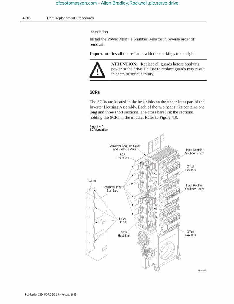
4–16 Part Replacement Procedures
Publication 1336 FORCE-6.15 – August, 1999
Installation
Install the Power Module Snubber Resistor in reverse order ofremoval.
Important: Install the resistors with the markings to the right.
!ATTENTION: Replace all guards before applyingpower to the drive. Failure to replace guards may resultin death or serious injury.
SCRs
The SCRs are located in the heat sinks on the upper front part of theInverter Housing Assembly. Each of the two heat sinks contains onelong and three short sections. The cross bars link the sections,holding the SCRs in the middle. Refer to Figure 4.8.
Figure 4.7SCR Location
AB0603A
Input RectifierSnubber Board
Guard
Horizontal InputBus Bars
OffsetFlex Bus
OffsetFlex Bus
Input RectifierSnubber Board
Converter Back-up Coverand Back-up Plate
ScrewHoles
SCRHeat Sink
SCRHeat Sink
efesotomasyon.com - Allen Bradley,Rockwell,plc,servo,drive

4–17Part Replacement Procedures
Publication 1336 FORCE-6.15 – August, 1999
Removal
!ATTENTION: Disconnect and lock out power fromthe drive before disassembling the drive. Failure todisconnect power may result in death or serious injury.Verify bus voltage by measuring the voltage betweenthe Negative Capacitor Bus and both ends of all three350 amp fuses. An open fuse does not show voltageacross both ends of the fuse. Failure to measure voltageat both ends of the fuses may result in death or seriousinjury. Refer to Figure 2.5. Do not attempt to service thedrive until the bus voltage has discharged to zero volts.
!ATTENTION: Hazard of electric shock exists. Up to1,600 VDC will be on Power Module Snubber BoardConnector J1 if the Snubber Resistor is open. Measurefor zero VDC from Snubber Board terminal TP3 toplus (+) bus before removing Connector J1. Use aresistor greater than 1 ohm and less than 100 ohm,rated for 25 watts minimum, between TP3 and plus (+)bus to discharge any voltage. Refer to Chapter 2 –Disassembly and Access Procedures, Removing aPower Module Snubber Board.
!ATTENTION: Wear a wrist-type grounding strapwhen servicing 1336 FORCE Drives. Failure to protectdrive components against ESD may damage drivecomponents. Refer to Electrostatic DischargePrecautions at the beginning of this chapter.
Important: Before you remove connections and wires from thedrive components, mark the connections and wires tocorrespond with their component connections andterminals to prevent incorrect wiring during assembly.
Access the heat sink:
1. Remove power from the drive.
2. Open the PC Board Mounting Frame. Refer to Opening the DriveEnclosure in Chapter 2.
3. Check for zero volts between +DC and –DC. Refer to Figure 2.5.
4. Check for the absence of control voltage at:
• TB20 and TB21 on drives using a PLC Comm Adapter Board• TB5, TB6, and TB7 on drives using a Standard Adapter Board
efesotomasyon.com - Allen Bradley,Rockwell,plc,servo,drive

4–18 Part Replacement Procedures
Publication 1336 FORCE-6.15 – August, 1999
5. Access the Inverter Housing Assembly. Refer to Chapter 2 –Disassembly and Access Procedures, Access to the InverterHousing Assembly.
6. Remove the Input Rectifier Snubber Boards. Refer to Chapter 2 –Disassembly and Access Procedures, Removing an InputRectifier Snubber Board.
7. Remove the snubber insulator and attached snubber buses.
Figure 4.8SCR Heat Sinks
AB0628A
Thermal SwitchSW1
Cross Bar
Roll Pin
SCR
Spring BarsHeat Sink
Converter Back-up Plate
Nut Bar
ConverterBack-up Cover
Remove the short section of the heat sink:
1. Remove the nuts from the ends of the cross bars.
2. Remove the spring bars.
3. Remove the short section of the heat sink. The long section,attached to the Converter Back-up Plate, remains in place.
efesotomasyon.com - Allen Bradley,Rockwell,plc,servo,drive

4–19Part Replacement Procedures
Publication 1336 FORCE-6.15 – August, 1999
Access the SCRs:
1. Remove the wires from the SCR.
2. Remove the SCR.
Installation
1. Adjust the roll pins in each heat sink half to extend 1.5 mm(0.060 in) toward the inside of the heat sink.
2. Apply silicone oil to the heat sink in the areas around the rollpins.
3. Clean the surface of the SCR and place it on the roll pin.
4. Apply silicone oil to the other side of the SCR.
5. Install the SCR Heat Sink in reverse order of removal. Allowaccess to the SCR gate connections.
6. Attach the wires to the SCR.
Important: Refer to the torque gauge on the spring bars on the leftside of the heat sink. Without load, the torque gaugeshould read zero. If it does not, replace the spring barassembly. Refer to Chapter 2 – Disassembly and AccessProcedures, Fastener Torque Specifications.
!ATTENTION: Replace all guards before applyingpower to the drive. Failure to replace guards may resultin death or serious injury.
efesotomasyon.com - Allen Bradley,Rockwell,plc,servo,drive

4–20 Part Replacement Procedures
Publication 1336 FORCE-6.15 – August, 1999
Fan and Transformer Assembly
The two fans are located at the bottom of the Inverter HousingAssembly. The Fan Transformer and Fan Capacitors are located inthe bottom left corner, attached to Fan 1. Both fans and theTransformer Assembly can be replaced without pulling out theInverter Housing Assembly.
Figure 4.9Fan and Transformer Assembly
AB0610A
Fan 1
Fan Cover
FanTransformer
FanCapacitor
Fan 2
Fan Cover
efesotomasyon.com - Allen Bradley,Rockwell,plc,servo,drive

4–21Part Replacement Procedures
Publication 1336 FORCE-6.15 – August, 1999
Removal
!ATTENTION: Disconnect and lock out power fromthe drive before disassembling the drive. Failure todisconnect power may result in death or serious injury.Verify bus voltage by measuring the voltage betweenthe Negative Capacitor Bus and both ends of all three350 amp fuses. An open fuse does not show voltageacross both ends of the fuse. Failure to measure voltageat both ends of the fuses may result in death or seriousinjury. Refer to Figure 2.5. Do not attempt to service thedrive until the bus voltage has discharged to zero volts.
!ATTENTION: Hazard of electric shock exists. Up to1,600 VDC will be on Power Module Snubber BoardConnector J1 if the Snubber Resistor is open. Measurefor zero VDC from Snubber Board terminal TP3 toplus (+) bus before removing Connector J1. Use aresistor greater than 1 ohm and less than 100 ohm,rated for 25 watts minimum, between TP3 and plus (+)bus to discharge any voltage. Refer to Chapter 2 –Disassembly and Access Procedures, Removing aPower Module Snubber Board.
!ATTENTION: Wear a wrist-type grounding strapwhen servicing 1336 FORCE Drives. Failure to protectdrive components against ESD may damage drivecomponents. Refer to Electrostatic DischargePrecautions at the beginning of this chapter.
Important: Before you remove connections and wires from thedrive components, mark the connections and wires tocorrespond with their component connections andterminals to prevent incorrect wiring during assembly.
1. Remove power from the drive.
2. Open the PC Board Mounting Frame. Refer to Opening the DriveEnclosure in Chapter 2.
3. Check for zero volts between +DC and –DC. Refer to Figure 2.5.
4. Check for the absence of control voltage at:
• TB20 and TB21 on drives using a PLC Comm Adapter Board• TB5, TB6, and TB7 on drives using a Standard Adapter Board
efesotomasyon.com - Allen Bradley,Rockwell,plc,servo,drive
4–22 Part Replacement Procedures
Publication 1336 FORCE-6.15 – August, 1999
Remove the Fan Transformer:
1. Remove the wiring harness to the Fan Transformer Assembly.
2. Turn the thumb latch, fastening the Transformer Assembly to Fan1, 1/4 turn counterclockwise.
3. Tilt the Transformer Assembly forward and lift it from themounting bracket.
Remove Fan 1:
1. Disconnect the fan wiring harness.
2. Pull down on both spring pins fastening the fan to the InverterHousing Assembly.
3. Pull the fan toward you to remove it.
Remove Fan 2:
1. Disconnect the Fan wiring harness.
2. Remove the screws fastening the fan cover to the fan.
3. Turn the standoffs, fastening the fan to the Inverter HousingAssembly, 1/4 turn counterclockwise to remove the fan.
Installation
Install the Fan and Transformer Assembly in reverse order of removal.
!ATTENTION: Replace all guards before applyingpower to the drive. Failure to replace guards may resultin death or serious injury.
efesotomasyon.com - Allen Bradley,Rockwell,plc,servo,drive
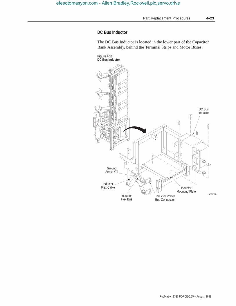
4–23Part Replacement Procedures
Publication 1336 FORCE-6.15 – August, 1999
DC Bus Inductor
The DC Bus Inductor is located in the lower part of the CapacitorBank Assembly, behind the Terminal Strips and Motor Buses.
Figure 4.10DC Bus Inductor
AB0611B
DC BusInductor
InductorMounting Plate
Inductor PowerBus Connection
InductorFlex Cable
InductorFlex Bus
GroundSense CT
efesotomasyon.com - Allen Bradley,Rockwell,plc,servo,drive
4–24 Part Replacement Procedures
Publication 1336 FORCE-6.15 – August, 1999
Removal
!ATTENTION: Disconnect and lock out power fromthe drive before disassembling the drive. Failure todisconnect power may result in death or serious injury.Verify bus voltage by measuring the voltage betweenthe Negative Capacitor Bus and both ends of all three350 amp fuses. An open fuse does not show voltageacross both ends of the fuse. Failure to measure voltageat both ends of the fuses may result in death or seriousinjury. Refer to Figure 2.5. Do not attempt to service thedrive until the bus voltage has discharged to zero volts.
!ATTENTION: Wear a wrist-type grounding strapwhen servicing 1336 FORCE Drives. Failure to protectdrive components against ESD may damage drivecomponents. Refer to Electrostatic DischargePrecautions at the beginning of this chapter.
Important: Before you remove connections and wires from thedrive components, mark the connections and wires tocorrespond with their component connections andterminals to prevent incorrect wiring during assembly.
1. Remove power from the drive.
2. Open the PC Board Mounting Frame. Refer to Opening the DriveEnclosure in Chapter 2.
3. Check for zero volts between +DC and –DC. Refer to Figure 2.5.
4. Check for the absence of control voltage at:
• TB20 and TB21 on drives using a PLC Comm Adapter Board• TB5, TB6, and TB7 on drives using a Standard Adapter Board
5. Access the Capacitor Bank Assembly. Refer to Chapter 2 –Disassembly and Access Procedures, Access to the CapacitorBank Assembly.
6. Remove the Inductor Flex Cable and the Ground Sense CT. Referto Removing the Ground Sense CT in this chapter.
7. Remove the Inductor Flex Bus.
8. Remove the two inductor power bus connections.
9. Remove the screws fastening the inductor to the InductorMounting Plate.
efesotomasyon.com - Allen Bradley,Rockwell,plc,servo,drive

4–25Part Replacement Procedures
Publication 1336 FORCE-6.15 – August, 1999
Important: Note the position and orientation of the Ground SenseCT (CT3) around the (–)Bus terminal at the top of theDC Bus Inductor. The Ground Sense CT is removedwith the inductor. Install the Ground Sense CT in thesame position. Check that the (+)Bus cable to the fusepasses through the Ground Sense CT during assembly.
10.Remove the DC Bus Inductor from the drive.
Installation
Install the DC Bus Inductor in reverse order of removal. Refer toChapter 2 – Disassembly and Access Procedures, Fastener TorqueSpecifications.
!ATTENTION: Replace all guards before applyingpower to the drive. Failure to replace guards may resultin death or serious injury.
efesotomasyon.com - Allen Bradley,Rockwell,plc,servo,drive

4–26 Part Replacement Procedures
Publication 1336 FORCE-6.15 – August, 1999
Ground Sense CT
The Ground Sense CT is located between the DC Bus Inductor andthe Transitional Bus Bar Assembly.
Figure 4.11Ground Sense CT
AB0612A
GroundSense CTConnector to Gate
Driver Board J2
Removal
!ATTENTION: Disconnect and lock out power fromthe drive before disassembling the drive. Failure todisconnect power may result in death or serious injury.Verify bus voltage by measuring the voltage betweenthe Negative Capacitor Bus and both ends of all three350 amp fuses. An open fuse does not show voltageacross both ends of the fuse. Failure to measure voltageat both ends of the fuses may result in death or seriousinjury. Refer to Figure 2.5. Do not attempt to service thedrive until the bus voltage has discharged to zero volts.
!ATTENTION: Wear a wrist-type grounding strapwhen servicing 1336 FORCE Drives. Failure to protectdrive components against ESD may damage drivecomponents. Refer to Electrostatic DischargePrecautions at the beginning of this chapter.
efesotomasyon.com - Allen Bradley,Rockwell,plc,servo,drive

4–27Part Replacement Procedures
Publication 1336 FORCE-6.15 – August, 1999
Important: Before you remove connections and wires from thedrive components, mark the connections and wires tocorrespond with their component connections andterminals to prevent incorrect wiring during assembly.
1. Remove power from the drive.
2. Open the PC Board Mounting Frame. Refer to Opening the DriveEnclosure in Chapter 2.
3. Check for zero volts between +DC and –DC. Refer to Figure 2.5.
4. Check for the absence of control voltage at:
• TB20 and TB21 on drives using a PLC Comm Adapter Board• TB5, TB6, and TB7 on drives using a Standard Adapter Board
5. Access the Capacitor Bank Assembly. Refer to Chapter 2 –Disassembly and Access Procedures, Access to the CapacitorBank Assembly.
6. Remove the Ground Sense CT connector J2 from the Gate DriverBoard.
7. Remove the nut and washers fastening the end of the InductorFlexible Cable to the right-angled connector on the right side ofthe DC Bus Inductor.
8. Remove the Inductor Flex Cable from the right side inductorpower bus connection.
9. Slide the Ground Sense CT from the Inductor Flex Cable.
Installation
Install the Ground Sense CT in reverse order of removal, insertingthe Inductor Flex Cable through the center of the Ground Sense CT.Refer to Chapter 2 – Disassembly and Access Procedures, FastenerTorque Specifications.
!ATTENTION: A possible short-circuit hazard exists.Position the fuse-to-inductor wire with theshrink-wrapped end of the wire connected to the DCBus Inductor. Failure to position the wire as illustratedmay result in serious injury or equipment damage.
!ATTENTION: Replace all guards before applyingpower to the drive. Failure to replace guards may resultin death or serious injury.
efesotomasyon.com - Allen Bradley,Rockwell,plc,servo,drive

4–28 Part Replacement Procedures
Publication 1336 FORCE-6.15 – August, 1999
Bus Fuses
The Bus Fuses are located on the Transitional Bus Bar assembly.
Figure 4.12Bus Fuse
AB0613A
Bus Fuse
Removal
!ATTENTION: Disconnect and lock out power fromthe drive before disassembling the drive. Failure todisconnect power may result in death or serious injury.Verify bus voltage by measuring the voltage betweenthe Negative Capacitor Bus and both ends of all three350 amp fuses. An open fuse does not show voltageacross both ends of the fuse. Failure to measure voltageat both ends of the fuses may result in death or seriousinjury. Refer to Figure 2.5. Do not attempt to service thedrive until the bus voltage has discharged to zero volts.
Part Replacement Procedures
efesotomasyon.com - Allen Bradley,Rockwell,plc,servo,drive
4–29Part Replacement Procedures
Publication 1336 FORCE-6.15 – August, 1999
!ATTENTION: Wear a wrist-type grounding strapwhen servicing 1336 FORCE Drives. Failure to protectdrive components against ESD may damage drivecomponents. Refer to Electrostatic DischargePrecautions at the beginning of this chapter.
Important: Before you remove connections and wires from thedrive components, mark the connections and wires tocorrespond with their component connections andterminals to prevent incorrect wiring during assembly.
Access the drive:
1. Remove power from the drive.
2. Open the PC Board Mounting Frame. Refer to Opening the DriveEnclosure in Chapter 2.
3. Check for zero volts between +DC and –DC. Refer to Figure 2.5.
4. Check for the absence of control voltage at:
• TB20 and TB21 on drives using a PLC Comm Adapter Board• TB5, TB6, and TB7 on drives using a Standard Adapter Board
5. Remove the nuts and washers fastening the Bus Fuse to the drive.
Installation
Install the Bus Fuse in reverse order of removal. Refer toChapter 2 – Disassembly and Access Procedures, Fastener TorqueSpecifications.
!ATTENTION: Replace all guards before applyingpower to the drive. Failure to replace guards may resultin death or serious injury.
efesotomasyon.com - Allen Bradley,Rockwell,plc,servo,drive

4–30 Part Replacement Procedures
Publication 1336 FORCE-6.15 – August, 1999
LEMs
The LEMs are located in the Capacitor Bank Assembly, above theTerminal Strips.
Figure 4.13LEMs
AB0614A
LEM U-ShapedTop Plate
LEM U-ShapedPlate
LEM MountingPlate
LEM
Removal
!ATTENTION: Disconnect and lock out power fromthe drive before disassembling the drive. Failure todisconnect power may result in death or serious injury.Verify bus voltage by measuring the voltage betweenthe Negative Capacitor Bus and both ends of all three350 amp fuses. An open fuse does not show voltageacross both ends of the fuse. Failure to measure voltageat both ends of the fuses may result in death or seriousinjury. Refer to Figure 2.5. Do not attempt to service thedrive until the bus voltage has discharged to zero volts.
!ATTENTION: Wear a wrist-type grounding strapwhen servicing 1336 FORCE Drives. Failure to protectdrive components against ESD may damage drivecomponents. Refer to Electrostatic DischargePrecautions at the beginning of this chapter.
efesotomasyon.com - Allen Bradley,Rockwell,plc,servo,drive

4–31Part Replacement Procedures
Publication 1336 FORCE-6.15 – August, 1999
Important: Before you remove connections and wires from thedrive components, mark the connections and wires tocorrespond with their component connections andterminals to prevent incorrect wiring during assembly.
Access the LEMs:
1. Remove power from the drive.
2. Open the PC Board Mounting Frame. Refer to Opening the DriveEnclosure in Chapter 2.
3. Check for zero volts between +DC and –DC. Refer to Figure 2.5.
4. Check for the absence of control voltage at:
• TB20 and TB21 on drives using a PLC Comm Adapter Board• TB5, TB6, and TB7 on drives using a Standard Adapter Board
5. Access the Capacitor Bank Assembly. Refer to Chapter 2 –Disassembly and Access Procedures, Access to the CapacitorBank Assembly.
Remove the LEM:
1. Remove the wires from the LEM connectors.
2. Remove the two screws fastening the LEM mounting plate tothe LEM.
3. Remove the LEM U-shaped top plate and the LEM U-shaped plate.
4. Remove the screws and standoffs fastening the LEM to theassembly frame.
5. Remove the Terminal Strip from the motor bus.
6. Disconnect the motor bus from the Motor Bus Support.
7. Disconnect the motor bus at its upper end.
8. Remove the motor bus and LEM from the Capacitor BankAssembly frame.
9. Remove the LEM from the motor bus.
Installation
Install the LEMs in reverse order of removal. Refer to Chapter 2 –Disassembly and Access Procedures, Fastener Torque Specifications.
!ATTENTION: Replace all guards before applyingpower to the drive. Failure to replace guards may resultin death or serious injury.
efesotomasyon.com - Allen Bradley,Rockwell,plc,servo,drive

4–32 Part Replacement Procedures
Publication 1336 FORCE-6.15 – August, 1999
MOV Surge Suppressor
The MOV Surge Suppressor is located on the left side of the InverterHousing Assembly in the top-left corner at the back of the drive nearthe vertical bus bars.
The MOV protects the drive from high voltage surges aboveapproximately 1,000 volts. Replace it if it is burned, expanded, orruptured after a lightening strike, or inadvertent connection of thedrive input to a voltage source substantially above nameplatevoltage.
Figure 4.14MOV Surge Suppressor
AB0617A
MOV SurgeSuppressor
Removal
!ATTENTION: Disconnect and lock out power fromthe drive before disassembling the drive. Failure todisconnect power may result in death or serious injury.Verify bus voltage by measuring the voltage betweenthe Negative Capacitor Bus and both ends of all three350 amp fuses. An open fuse does not show voltageacross both ends of the fuse. Failure to measure voltageat both ends of the fuses may result in death or seriousinjury. Refer to Figure 2.5. Do not attempt to service thedrive until the bus voltage has discharged to zero volts.
efesotomasyon.com - Allen Bradley,Rockwell,plc,servo,drive

4–33Part Replacement Procedures
Publication 1336 FORCE-6.15 – August, 1999
!ATTENTION: Hazard of electric shock exists. Up to1,600 VDC will be on Power Module Snubber BoardConnector J1 if the Snubber Resistor is open. Measurefor zero VDC from Snubber Board terminal TP3 toplus (+) bus before removing connector J1. Use aresistor greater than 1 ohm and less than 100 ohm,rated for 25 watts minimum, between TP3 and plus (+)bus to discharge any voltage. Refer to Chapter 2 –Disassembly and Access Procedures, Removing aPower Module Snubber Board.
!ATTENTION: Wear a wrist-type grounding strapwhen servicing 1336 FORCE Drives. Failure to protectdrive components against ESD may damage drivecomponents. Refer to Electrostatic DischargePrecautions at the beginning of this chapter.
Important: Before you remove connections and wires from thedrive components, mark the connections and wires tocorrespond with their component connections andterminals to prevent incorrect wiring during assembly.
1. Remove power from the drive.
2. Open the PC Board Mounting Frame. Refer to Opening the DriveEnclosure in Chapter 2.
3. Check for zero volts between +DC and –DC. Refer to Figure 2.5.
4. Check for the absence of control voltage at:
• TB20 and TB21 on drives using a PLC Comm Adapter Board• TB5, TB6, and TB7 on drives using a Standard Adapter Board
5. Access the Inverter Housing Assembly. Refer to Chapter 2 –Disassembly and Access Procedures, Access to the InverterHousing Assembly.
6. Remove the MOV wire harness from the vertical bus bars on theleft at the back of the Inverter Housing Assembly.
7. Remove the screw fastening the MOV to the Inverter weldment.
efesotomasyon.com - Allen Bradley,Rockwell,plc,servo,drive

4–34 Part Replacement Procedures
Publication 1336 FORCE-6.15 – August, 1999
Installation
Install the MOV Surge Suppressor in reverse order of removal. Referto Chapter 2 – Disassembly and Access Procedures, Fastener TorqueSpecifications.
!ATTENTION: Replace all guards before applyingpower to the drive. Failure to replace guards may resultin death or serious injury.
efesotomasyon.com - Allen Bradley,Rockwell,plc,servo,drive

Chapter 5
Publication 1336 FORCE-6.15 – August, 1999
Replacement Parts List
This chapter illustrates and lists replacement parts for the 1336FORCE Drives rated B300 – B600, C300 – C600, and BX250, anddescribes replacement parts ordering procedures.
The following illustration and table show you parts, part names, partnumbers, locations, and chapters for replacement procedures.
For your convenience, the Allen-Bradley Drives Division and theAllen-Bradley Support Division provide efficient and convenientrepair and exchange for eligible equipment.
A product service report number is required to return any equipmentfor repair. Your local Allen-Bradley distributor or area sales andsupport office can provide you with a product service report number.
You should return equipment to be repaired to the area sales andsupport center nearest you. Reference the product service reportnumber on the carton and packing slip. Include:
• Your company name
• Your company address
• The repair purchase order number
• A brief description of the problem
Contact your local Allen-Bradley distributor or sales office for acomplete listing of area sales and support centers near you.
For parts catalog numbers, refer to the 1336 PLUS Spare PartsPricing publication included with your drive documentation set.
Chapter Objectives
Ordering ReplacementParts
efesotomasyon.com - Allen Bradley,Rockwell,plc,servo,drive

5–2 Replacement Parts List
Publication 1336 FORCE-6.15 – August, 1999
Figure 5.1Parts for B300 – B600, C300 – C600, and BX250 Drives
AB0708A
12
5
3
46 7
8
9
10
11
1213
14
15
16
17
18
19
20
21
22
23
24
Replacement Parts Listing
efesotomasyon.com - Allen Bradley,Rockwell,plc,servo,drive
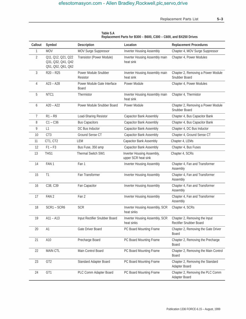
5–3Replacement Parts List
Publication 1336 FORCE-6.15 – August, 1999
Table 5.AReplacement Parts for B300 – B600, C300 – C600, and BX250 Drives
Callout Symbol Description Location Replacement Procedures
1 MOV MOV Surge Suppressor Inverter Housing Assembly Chapter 4, MOV Surge Suppressor
2 Q11, Q12, Q21, Q22Q31, Q32, Q41, Q42Q51, Q52, Q61, Q62
Transistor (Power Module) Inverter Housing Assembly mainheat sink
Chapter 4, Power Modules
3 R20 – R25 Power Module SnubberResistor
Inverter Housing Assembly mainheat sink
Chapter 2, Removing a Power ModuleSnubber Board
4 A23 – A28 Power Module Gate InterfaceBoard
Power Module Chapter 4, Power Modules
5 NTC1 Thermistor Inverter Housing Assembly mainheat sink
Chapter 4, Thermistor
6 A20 – A22 Power Module Snubber Board Power Module Chapter 2, Removing a Power ModuleSnubber Board
7 R1 – R9 Load-Sharing Resistor Capacitor Bank Assembly Chapter 4, Bus Capacitor Bank
8 C1 – C36 Bus Capacitors Capacitor Bank Assembly Chapter 4, Bus Capacitor Bank
9 L1 DC Bus Inductor Capacitor Bank Assembly Chapter 4, DC Bus Inductor
10 CT3 Ground Sense CT Capacitor Bank Assembly Chapter 4, Ground Sense CT
11 CT1, CT2 LEM Capacitor Bank Assembly Chapter 4, LEMs
12 F1 – F3 Bus Fuse, 350 amp Capacitor Bank Assembly Chapter 4, Bus Fuses
13 THS1 Thermal Switch SW1 Inverter Housing Assembly,upper SCR heat sink
Chapter 4, SCRs
14 FAN 1 Fan 1 Inverter Housing Assembly Chapter 4, Fan and TransformerAssembly
15 T1 Fan Transformer Inverter Housing Assembly Chapter 4, Fan and TransformerAssembly
16 C38, C39 Fan Capacitor Inverter Housing Assembly Chapter 4, Fan and TransformerAssembly
17 FAN 2 Fan 2 Inverter Housing Assembly Chapter 4, Fan and TransformerAssembly
18 SCR1 – SCR6 SCR Inverter Housing Assembly, SCRheat sinks
Chapter 4, SCRs
19 A11 – A13 Input Rectifier Snubber Board Inverter Housing Assembly, SCRheat sinks
Chapter 2, Removing the InputRectifier Snubber Board
20 A1 Gate Driver Board PC Board Mounting Frame Chapter 2, Removing the Gate DriverBoard
21 A10 Precharge Board PC Board Mounting Frame Chapter 2, Removing the PrechargeBoard
22 MAIN CTL Main Control Board PC Board Mounting Frame Chapter 2, Removing the Main ControlBoard
23 GT2 Standard Adapter Board PC Board Mounting Frame Chapter 2, Removing the StandardAdapter Board
24 GT1 PLC Comm Adapter Board PC Board Mounting Frame Chapter 2, Removing the PLC CommAdapter Board
efesotomasyon.com - Allen Bradley,Rockwell,plc,servo,drive

5–4 Replacement Parts List
Publication 1336 FORCE-6.15 – August, 1999
This Page Intentionally Left Blank.
efesotomasyon.com - Allen Bradley,Rockwell,plc,servo,drive

Chapter 6
Publication 1336 FORCE-6.15 – August, 1999
Schematics — 300 – 600 HP 1336FORCE Drives
efesotomasyon.com - Allen Bradley,Rockwell,plc,servo,drive

6–2 Schematics — 300 – 600 HP 1336 FORCE Drives
Publication 1336 FORCE-6.15 – August, 1999
AB0725A
SCHEMATIC DIAGRAMSTAND ALONEX250 – 650 HP
CT3
INV+
INV–
THS1
TO FAN CIRCUIT
SEE DETAILS
SEETABLE 1
CF3
PE
T–L3
S–L2
ACINPUTPOWER50/60HZ
CF1
CF2
CUSTOMERFUSING
R–L1
PE
CNV–
SCR4
MOV1
G2
K2
SCR6
G2
K2
G1
SCR1
K1
PM1
CNV+
G1
SCR3
K1
PM2 PM3
SCR2
(4) (3)
G2
K2
DC–
G1
SCR5
K1
(1) (2)
L1
DC–
DC+
CONVSNUBBER
CONVSNUBBER
CONVSNUBBER
A11 A12 A13
DC+
A10
STANDARDPRECHARGEBOARD F1 F2
S2G
R2G
R2K
910
T2G
T2K
S2K
J256 2 1
T1K
T1G
S1K
S1G
R1K
R1G
2J1
6 5 34 1
SEE TABLE 3
F3
12
89
1011
J3 7
– BU
S
+ BU
S
J4
1 4
4
1
AC LINE
–15VCOMMON+5V/CHARGE
+15V
+SMPS
–SMPS
PEPE PE
CAPACITOR
105061
C41
C40
X
TB1
TB1
BANKSEE DETAILS
efesotomasyon.com - Allen Bradley,Rockwell,plc,servo,drive

6–3Schematics — 300 – 600 HP 1336 FORCE Drives
Publication 1336 FORCE-6.15 – August, 1999
AB0726A
E1
B1
C1
E1
B1
C1 C1
E1
C1
B1
E1
B1
C1
E1
C1
B1
E1
B1
C1
E1
C1
B1
E1
B1
C1
E1
C1
B1
E1
B1
C1
E1
C1
B1
E1
B1
NTC1
NTC
TOMAIN
CONTROLBOARD
R24 R25R22 R23R20 R21
CT 2CT 1
A20 A21 A22
A23 A24 A26A25 A28A27
C1E2E1B2B1C1
G1
G2
E1 G2 C1
G1
G2
E1 E2 C1
E1G2
G1
E2 E1C1
G2
G1
E2 G1
G2
C1
E2E1
J1
J2
1
3
1
3 J2
J1
1
3
1
3 J2
J1
1
3
1
3
Q11
Q41 Q42
Q12 Q31
Q61
Q32
Q62
Q51
Q21
Q52
Q22
1 4 5 1 4 5 1 4 5 1 4 5 1 4 5 1 4 5
GATEDRIVERBOARD
WP_
EMIT
POS_
BUS
U_A
MPS
+W
_NEG
–
V_PO
S–V_
NEG
–W
_PO
S–
V_VO
LTS
U_V
OLT
S
U_A
MPS
–W
_AM
PS+
W_A
MPS
–
NEG
_CAP
W_V
OLT
SV_
CO
M N
CN
EG_B
US
171413 1615 221918 2120 252423 26 27
J1
+5V
EE_I
O
DES
ATAC
LIN
E/C
HAR
GE
GN
D_S
HO
RT
EE_S
KEE
_CS
PILO
TC
VER
IFY
+5V
–15V
–15V
+15V
+15V+5
V
DG
ND
+24V
ISO
12V
ISO
12R
TND
GN
D
3833302928 3231 3534 3736 4039 434241 464544 4847
A1
8
ACT1
ACT2
J2
1 2
+BU
S
–BU
S
+15
J10
1 4
WN
_GAT
E
U_A
MPS
INTE
RLO
CK
W_A
MPS
–15V
+15
–15
2
J6
567 34 1
WP_
GAT
E
UN
_EM
ITU
N_G
ATE
VN_G
ATE
VN_E
MIT
WN
_EM
IT
J7321 4 5 6 1
+EXT. RES.
–EXT. RES.
120VACTB5
SEE TABLE 3
+5V
+5V
TE
TB7
5049 1 2
F1 F3
EXTERNAL DC BUSINPUT CONNECTION
HIG
H V
OLT
AGE
+DC
AU
X IN
HIG
H V
OLT
AGE
–DC
AU
X IN
1
TB6
3
J131
4
6
43
524V– OUT
120RTN24V+ OUT
J8
UP_
GAT
E
VP_E
MIT
VP_G
ATE
VN_C
OL
WN
_CO
L
2 3 876
UP_
CO
LVP
_CO
LW
P_C
OL
UN
_CO
LU
P_EM
IT
131211 1716 18
J5
1 42 6
12
AC FAN1AC FAN2
EXTERNALBUSDISCHARGERESISTOR
CONTACTORINTERFACE
M1X1
M1K1M1K2M1X2
TO MAIN CONTROL BOARD
6U
_NEG
+
DG
ND
U_P
OS+
DG
ND
DG
ND
DG
ND
+24V DC AUX INPUT–24V DC AUX INPUT
12
1
1TB4
32 54
5 J9
34
2
6
AC LINE
–15VCOMMON
+5V/CHARGE
+15V
+SMPS
–SMPS 9
12
W_N
EG+
U_P
OS–
V_PO
S+V_
NEG
+W
_PO
S+
U_N
EG–
987 1110 12
POWEROUTPUTAC
W–M3
V–M2
U–M1
PE–15 1
W_AMPS+15 3
23
–15
U_AMPS
12
+15
TB1
efesotomasyon.com - Allen Bradley,Rockwell,plc,servo,drive

6–4 Schematics — 300 – 600 HP 1336 FORCE Drives
Publication 1336 FORCE-6.15 – August, 1999
ExternalFan 1
ExternalFan 2
AB0723A
C1 C2 C3 C4
C8C7C6C5
R1
R2
CAP DETAIL460V
C9 – C16
R3 – R4
C17 – C24
R5 – R6
D1
D2
D3F2
F1
F3
+
–R4 – R6
C13 – C24 C25 – C36
R7 – R9
C5
C9
–
CAP DETAIL575V
R3C10 C11 C12
C6 C7 C8R2
C1 C2 C3 C4R1
+
D3
F3
D2
F2
F1
D1
FAN 1
NOMINAL
TAPDEFINITION
–10%OPTIONAL 380
415
TRANSFORMER460
380/460V
N/A500
TRANSFORMER575
575V
BASED ON DRIVE INPUT VOLTAGE, EITHER A380/460V OR A 575V FAN AUTOTRANSFORMERWILL BE PROVIDED. THE TABLE BELOW DEFINESTHE AUTOTRANSFORMER TAP VOLTAGE.
C39
J3
J1
1 2 3 4
Z2 TK U2
GR
N/Y
J4
C38
J2
GR
N/Y
BRN
BLK
BLU
3 124
FAN 2
GRN/Y
WHITEBLK
WHITEWHITE
GRN/Y
WHITEBLK
BRN BRNW
HIT
E
BLK
TB1
JUMPERJUMPER
120V
21
12
C41
C40 C40
C41
SEE TABLE 2 SEE TABLE 2
575460 415
380
R–L1S–L2
3A
SEE TABLE 3
T1
F5F4
X X
Capacitor Detail
Fan Circiut Detail
575V 460V
efesotomasyon.com - Allen Bradley,Rockwell,plc,servo,drive

6–5Schematics — 300 – 600 HP 1336 FORCE Drives
Publication 1336 FORCE-6.15 – August, 1999
AB0724A
FUSE WILL CHANGE AMP RATING. THE TABLE BELOW DEFINES TABLE 2: BASED ON DRIVE HORSEPOWER, THE INVERTER DC + BUS
HP, 575VAC
HP, 380/460VAC
THE FUSE RATING.
ITEM B/M DIAGRAMSCHEMATIC
A1
A10A11–13A20–22A23–28
APPROVED EQUIVALENT MUST BE USED:BASED ON MAXIMUM DRIVE RATING THE FOLLOWING FUSES OR
TABLE 1: CUSTOMER FUSING
380/460V FUSE I/TYPE 575VAC FUSE CURRENT/TYPEHORSEPOWER
X250
300
ASSEMBLIES VERSUS FUSE & DOCUMENTATION INFORMATION.TABLE 3: THE FOLLOWING IS A LISTING OF ALL PRINTED CIRCUIT
THE FUSE RATING.
DESIGNATOR RATING TYPE P/N
FUSE INFORMATION
74101–163–XX 74101–167
74101–181–XX74101–367–XX74101–146–XX74101–177–XX
74101–17974101–36574101–14474101–175
F1–F3 1.5A/600V KTK–RF3F1
1.5A/600V KTK–R1.0A/600V KTK–R
NONENONENONE
25172–260–0825172–260–0925172–260–09
500HP, 380/460VAC
FUSE INFORMATION
RATING TYPE P/N
DRIVEHORSEPOWER,INPUT VOLTAGE
600HP, 575VAC
450 A70C OR FWH
300A
300A
A70Q
A70Q
25178–310–14
25178–310–14
74101–121 F4–F5 3A/600V FNQR 25184–254–20
500 A70C OR FWH
400
350
800 A70C OR FWH
500
450
900 A70C OR FWH
650
600
800 A70C OR FWH
600 A70C OR FWH
450 A70C OR FWH
800 A70C OR FWH
900 A70C OR FWH
450 A70C OR FWH
600 A70C OR FWH
800 A70C OR FWH
500 A70C OR FWH
400 A70C OR FWH
efesotomasyon.com - Allen Bradley,Rockwell,plc,servo,drive

6–6 Schematics — 300 – 600 HP 1336 FORCE Drives
Publication 1336 FORCE-6.15 – August, 1999
This Page Intentionally Left Blank.
efesotomasyon.com - Allen Bradley,Rockwell,plc,servo,drive

Glossary
Glossary
AC Contactor: An alternating-current (AC) contactor is designedfor the specific purpose of establishing or interrupting an AC Powercircuit.
Adjustable Speed: The concept of varying the speed of a motor,either manually or automatically. The desired operating speed (setspeed) is relatively constant regardless of load.
Adjustable Speed Drive (Electrical): The adjustable speed drive iscomprised of the motor, drive controller and operator’s controls(either manual or automatic).
Ambient Temperature: The temperature of the medium (air, water,earth) into which the heat of the equipment is dissipated.
Base Speed:The manufacturer’s nameplate rating where the motorwill develop rated power at rated load and voltage. With DC drives,it is commonly the point where full armature voltage is applied withfull-rated field excitation. With AC systems, it is commonly the pointwhere 60 Hz is applied to the induction motor.
BR: Refer to Bridge Rectifier.
Braking: A method of stopping or reducing the time required tostop an AC motor, and can be accomplished in several ways:
1. DC-Injection braking (AC drives) � A method which produceselectromagnetic braking forces in the motor by removing 2 ACmotor (stator) phases and injecting DC current. The result is alinear braking characteristic (ramp) that does not diminish withmotor speed. Application is normally limited to 10–20% of ratedmotor speed due to increased heating in the rotor.
2. Dynamic braking (AC drives) � A method which produceselectromagnetic braking forces in the motor by dissipatinggenerated power into the DC bus through a resistive load.Braking force remains constant and is only limited by the thermalcapacity of the resistors. The result is a linear brakingcharacteristic (ramp) that does not diminish with motor speed.
3. Regenerative braking � A method which produceselectromagnetic braking forces in the motor by electronicallycontrolling the return of generated power to the AC supply. Theresult is a controllable linear braking characteristic (ramp) thatdoes not diminish with motor speed.
efesotomasyon.com - Allen Bradley,Rockwell,plc,servo,drive

GlossaryG–2
Publication 1336 FORCE-6.15 – August, 1999
4. Motor-mounted or separately-mounted brake � Apositive-action, mechanical friction device. Normal configurationis such that when the power is removed, the brake is set. This canbe used as a holding brake. (Note: A separately mounted brake isnot one which is located on some part of the mechanical drivetrain other that the motor.)
Breakaway Torque: The torque required to start a machine fromstandstill. Breakaway torque is always greater than the torque neededto maintain motion.
Breakdown Torque: The breakdown torque of an AC motor is themaximum torque which it will develop with rated voltage applied atrated frequency.
Bridge Rectifier (Diode, SCR): A non-controlled, full-waverectifier that produces a constant, rectified, DC voltage. An SCRbridge rectifier is a full-wave rectifier with a DC output that can becontrolled by switching on the gate control element.
Bridge Rectifier: A full-wave rectifier that conducts current in onlyone direction of the input current. AC applied to the input results inapproximate DC at the output.
British Thermal Unit (BTU): The quantity of heat required to raiseone pound of water by one degree Fahrenheit.
BTU: Refer to British Thermal Unit.
Bus: A single path or multiple parallel paths for power or datasignals to which several devices may be connected at the same time.A bus may have several sources of supply and/or several sources ofdemand.
Bus Sense:A signal transducer that generates a signal proportionalto the current in the drive’s DC bus. The control logic uses this signalto sense the presence or absence of bus voltage.
CEMF: Refer to Counter Electromotive Force.
CMOS: Complimentary Metallic Oxide Semiconductor. Asemiconductor device in which an electric field controls theconductance of a channel under a metal electrode called a gate.
Cogging: A condition in which a motor does not rotate smoothly butsteps or jerks from one position to another during shaft revolution.Cogging is most pronounced at low motor speeds and can causeobjectionable vibrations in the driven machinery.
efesotomasyon.com - Allen Bradley,Rockwell,plc,servo,drive

Glossary G–3
Publication 1336 FORCE-6.15 – August, 1999
Constant Torque Range: A speed range in which a motor iscapable of delivering a constant torque, subject to cooling limitationsof the motor.
Constant Voltage Range:(AC Drives) The range of motoroperation where the drive’s output voltage is held constant as outputfrequency is varied. This speed range produces motor performancesimilar to a DC drive’s constant horsepower range.
Constant Volts per Hertz (V/Hz): The V/Hz relationship exists inAC drives where the output voltage is directly proportional tofrequency. This type of operation produces constant rated torque asthe motor’s speed varies.
Continuous Duty (CONT): A motor that can continue to operatewithout stopping and remain within the insulation temperature limitsafter it has reached normal operating (equilibrium) temperature.
Converter:
1. A device for changing AC to DC. This is accomplished throughuse of a diode rectifier or thyristor rectifier circuit.
2. A device for changing AC to DC to AC (e.g., adjustablefrequency drive). A frequency converter, such as that found in anadjustable frequency drive, consists of a rectifier, a DCintermediate circuit, an inverter, and a control unit.
Counter Electromotive Force (CEMF): The product of a motorarmature rotating in a magnetic field. This generating action takesplace whenever a motor is rotating. Under stable motoring conditionsthe generated voltage (CEMF) is equal to the voltage supplied to themotor minus small losses. However, the polarity of the CEMF isopposite to that of the power being supplied to the armature.
Current Limiting: An electronic method of limiting the maximumcurrent available to the motor. This is adjustable so that the motor’smaximum current can be controlled. It can also be preset as aprotective device to protect both the motor and the control fromextended overloads.
DC Boost: Compensates for the voltage drop across the resistanceof an AC motor circuit and the resulting reduction in torque.
DC Bus: A drive’s power structure that transmits a rectified AC linepower from the bridge rectifier to the output transistors.
DC Hold: Describes a “holding brake” function to stop motorrotation after a ramp-to-stop function is activated.
Diode: A solid-state uni-directional conductor.
efesotomasyon.com - Allen Bradley,Rockwell,plc,servo,drive

GlossaryG–4
Publication 1336 FORCE-6.15 – August, 1999
Drift: A slow change in some characteristic of a device. For a drive,it is the deviation from the initial set speed with no load change overa specific time period. Normally the drive must be operated for aspecified warm-up time at a specified ambient temperature beforedrift specifications apply. Drift is normally caused by randomchanges in operating characteristics of various control components.
Drive Controller (Variable Speed Drive) (Drive): An electronicdevice that can control the speed, torque, horsepower, and directionof an AC or DC motor.
1. PWM drive � is a motor drive using pulse-width modulationtechniques to control power to the motor. A high-efficiency driveused for high-response applications.
2. SCR drive � is a motor drive that uses SCRs as the power controlelements. Usually used for low-bandwidth high-power applications.
3. Servo drive � is a motor drive that uses internal feedback loopsfor motor current and/or velocity.
4. Vector drive � is an AC static motor drive using power-controltechniques that produce motor performance similar to DCstatic drives.
Duty Cycle:
1. The ratio of working time to total time for an intermittentlyoperating device. Usually expressed as a percentage.
2. The ratio of pulse width to the interval between like portions ofsuccessive pulses. Usually expressed as a percentage.
Dynamic Braking: Refer to Braking.
Efficiency: Ratio of output to input, indicated by a percentage. In amotor, it is the effectiveness with which the motor converts electricalenergy into mechanical energy. In a power supply, it is theeffectiveness with which the power supply converts AC power intoDC power.
Electrostatic Discharge (ESD):A static-electricity discharge thatmay damage drive components. Refer to the ESD precautions foundin this manual to guard against damage to drive components.
Enable: To activate logic by the removal of a suppression signal.
Enclosure: The housing in which equipment is mounted. They areavailable in designs for various environmental conditions. Refer toNEMA standard for specifications of different types of enclosures.
efesotomasyon.com - Allen Bradley,Rockwell,plc,servo,drive

Glossary G–5
Publication 1336 FORCE-6.15 – August, 1999
ENUM (Enumeration): An ANSI C standard extension to the Clanguage. An ENUM is a set of named integer constants that specifyall the legal values a variable of a given type may have. The keywordENUM signals the start of an enumeration type.
ESD: Refer to Electrostatic Discharge.
Floating Ground: An electrical circuit common which is not atearth ground potential or the same ground potential as circuitry withwhich it interfaces. A voltage difference can exist between thefloating ground and earth ground.
Force: The tendency to change the motion of an object with anexertion of energy from a separate source.
Full Load Torque: The full-load torque of a motor is the torquenecessary to produce rated horsepower at full-load speed.
Gate:
1. A logic element that blocks or passes a signal, depending on thestatus of specified input signals.
2. The control element of an SCR.
GND Sense:A current transducer that detects an unequal orimbalanced current in the three-phase AC line or DC bus of thedrive. The imbalance indicates an output ground fault condition.
Horsepower (hp): A unit of power: 1 hp = 33,000 ft-lb/min. =746 watts.
IEC: International Electrotechnical Commission.
IGBT: Refer to Insulated Gate Bipolar Transistor.
Induction Motor: An induction motor is an alternating-currentmotor in which the primary winding on one member is connected tothe power source. A secondary winding on the other member carriesthe induced current. There is no physical electrical connection to thesecondary winding; its current is induced.
Inertia: A measure of a body’s resistance to change in velocity,whether a body is at rest or moving at a constant velocity. Thevelocity can be either linear or rotational. The moment of inertia(WK2) is the product of the weight (W) of an object and the squareof the radius of gyration (K2). The radius of gyration is a measure ofhow the mass of the object is distributed about the axis of rotation.WK2 is usually expressed in units of lb-ft2.
Insulated Gate Bipolar Transistor (IGBT): A type of transistorcommonly used in drive-control devices.
efesotomasyon.com - Allen Bradley,Rockwell,plc,servo,drive

GlossaryG–6
Publication 1336 FORCE-6.15 – August, 1999
Integral-Horsepower Motor: A motor that has a continuous ratingof 1 hp or more, built into a frame.
International Organization for Standards (ISO): An organizationestablished to promote development of international standards.
Interposing Relay: An interposing relay is a relay that acceptscontrol signals of one logic level in order to provide isolated contactsignals in a circuit operating at a different logic level.
Inverter:
1. An AC adjustable frequency drive.
2. A particular section of an AC drive. This section uses the DCvoltage from a previous circuit stage (intermediate DC circuit) toproduce a pulse-width-modulated or stepped AC current orvoltage waveform that has characteristics similar to the desiredsine-wave frequency.
3. A circuit whose output signal is the inverse of its input (apositive-going pulse is inverted to a negative-going pulse, andvise versa).
ISO: Refer to International Organization for Standards.
Isolation Transformer:
1. A transformer that provides DC isolation from other equipmentnot connected to that transformer secondary.
2. A transformer that provides noise isolation between the primaryand secondary by such means as a Faraday shield.
Jogging:
1. In a numerical control system, an operator manually generatingmotion (continuously or incrementally) by closing a switch.
2. An operator generating motion by closing a switch.
Kinetic Energy: The energy of motion of a moving body.
LAD: Refer to Linear Acceleration/Deceleration.
LEM: A hall-effect current transducer that senses drive outputcurrent and generates a signal for the control logic.
Linear Acceleration/Deceleration (LAD): A circuit that controlsthe rate at which a motor is allowed to accelerate to a set speed ordecelerate to zero speed. On most drives, this circuit is adjustableand can be set to accommodate a particular application.
Linearity: A measure of how closely a characteristic follows astraight-line function.
efesotomasyon.com - Allen Bradley,Rockwell,plc,servo,drive

Glossary G–7
Publication 1336 FORCE-6.15 – August, 1999
Locked-Rotor Current: Steady-state current taken from the linecurrent with the a rotor at standstill (at rated voltage and frequency).This is the current when starting the motor and load.
Locked-Rotor Torque: The minimum torque that a motor willdevelop at rest for all angular positions of the rotor (with ratedvoltage applied at rated frequency).
Meggar Test: A test used to measure an insulation system’s resistance.This is usually measured in megohms by applying a high voltage.
MOV: Refer to Surge Protection.
National Electrical Code (NEC): A set of regulations governingthe construction and installation of electrical wiring and apparatus,established by the National Fire Protection Association and suitablefor mandatory application by governing bodies exercising legaljurisdiction. It is widely used by state and local authorities within theUnited States.
National Electrical Manufacturer’s Association (NEMA): Anon-profit organization organized and supported by electricalequipment and supply manufacturers. Some NEMA motor standardsinclude horsepower (hp) ratings, speeds, frame sizes and dimensions,torques, and drive enclosures.
NEC: Refer to National Electrical Code.
Negative Slope: The location on a V/Hz curve where the breakvoltage exceeds the base voltage.
NEMA: Refer to National Electrical Manufacturer’s Association.
Offset: The steady-state deviation of a controlled variable from afixed setpoint.
Op Amp: An operational amplifier. A high-gain stable linear DCamplifier that is designed to be used with external circuit elements.
Open Loop System:A control system that has no means ofcomparing the output with the input for control purposes.
Overload Capacity: The ability of the drive to withstand currentsbeyond the system’s continuous rating. It is normally specified as apercentage of full-load current endured for a specified time period.Overload capacity is defined by NEMA as 150% of rated full loadcurrent for one minute for “standard industrial DC motors.”
efesotomasyon.com - Allen Bradley,Rockwell,plc,servo,drive

GlossaryG–8
Publication 1336 FORCE-6.15 – August, 1999
PC:
1. Personal Computer.
2. Programmable Controller.
3. Printed Circuit.
Plugging: A type of motor braking provided by reversing either linevoltage polarity or phase sequence so that the motor develops acounter torque that exerts a retarding force to brake the motor.
Pot: A potentiometer, or variable resistor.
Power: Work done per unit of time. Measured in horsepower (hp) orwatts (W): 1 hp = 33,000 ft-lb/min. = 746 W.
Power Factor (Displacement):A measurement of the time phasedifference between the fundamental voltage and fundamental currentin an AC circuit. It represents the cosine of the phase angledifference. Fp = cos (α– β)
Power Factor (Distortion): A measurement of the ratio of the realpower (kW) to the apparent power (kVA). Distortion power factortakes into account harmonic voltage and current distortion as well asvoltage-to-current displacement.
Preform: A flexible material used between an electronic componentand the heat sink to which the component is attached. Preform providesmaximum heat dissipation from the component to the heat sink.
Preset Speed:Describes one or more fixed speeds at which adrive operates.
Programmable Controller: A solid-state control system that has auser-programmable memory for storage of instructions to implementspecific functions such as I/O control, logic, timing, counting, reportgeneration, communication, arithmetic, and data file manipulation. Acontroller consists of a central processor, input/output interface, andmemory. A controller is designed as an industrial control system.
Pull-In Torque: The maximum constant torque to which asynchronous motor accelerates into synchronism at rated voltageand frequency.
Pull-Out Torque: The maximum running torque of asynchronous motor.
efesotomasyon.com - Allen Bradley,Rockwell,plc,servo,drive

Glossary G–9
Publication 1336 FORCE-6.15 – August, 1999
Pull-Up Torque: The torque required to accelerate the load fromstandstill to full speed (where breakdown torque occurs), expressedin percent of running torque. It is the torque required not only toovercome friction, windage, and product loading but also toovercome the inertia of the machine. The torque required by amachine may not be constant after the machine has started to turn.This load type is characteristic of fans, centrifugal pumps, andcertain machine tools.
PWM: Pulse-width Modulation. A technique used to eliminate orreduce unwanted harmonic frequencies when inverting DC voltageto sine wave AC.
Reactance: Pure inductance or capacitance, expressed in ohms, in acircuit. It is the component of impedance to alternating current that isnot resistance.
Rectifier: A device that conducts current in only one direction,thereby transforming alternating current to direct current.
Regeneration: (AC drives) When the rotor synchronous frequencyis greater than the applied frequency.
Regenerative Braking: Slows or stops a motor throughregeneration. Refer to Regeneration and Braking.
Resolution: The smallest distinguishable increment into which aquantity can be divided (e.g., position or shaft speed). It is also thedegree to which nearly equal values of a quantity can bediscriminated. For rotary encoders, it is the number of uniqueelectrically identified positions occurring in 360 degrees of inputshaft rotation. For D/A or A/D conversion, may be expressed as thenumber of bits in the digital value that corresponds to a full-scaleanalog value.
SCR: Silicon Controlled Rectifier. A solid-state uni-directionallatching switch.
Service Factor: When used on a motor nameplate, a number thatindicates how much above the nameplate rating a motor can beloaded without causing serious degradation (i.e., a motor with 1.15S-F can produce 15% greater torque than one with 1.0 S-F).
Set Speed:The desired operating speed.
Shock Load: The load seen by a clutch, brake, or motor in a systemthat transmits high peak loads. This type of load is present incrushers, separators, grinders, conveyors, winches, and cranes.
efesotomasyon.com - Allen Bradley,Rockwell,plc,servo,drive

GlossaryG–10
Publication 1336 FORCE-6.15 – August, 1999
Slip: The difference between rotating magnetic field speed(synchronous speed) and rotor speed of AC induction motors.Usually expressed as a percentage of synchronous speed.
Slip Compensation: Monitors motor current and compensates forspeed lost due to increased motor slip. The amount of slip isproportional to the motor load.
Speed Range:The speed minimum and maximum at which a motormust operate under constant or variable torque load conditions. A50:1 speed range for a motor with top speed 1800 rpm means themotor must operate as low as 36 rpm and still remain withinregulation specification. Controllers are capable of widercontrollable speed ranges than motors because there is no thermallimitation, only electrical. Controllable speed range of a motor islimited by the ability to deliver 100% torque below base speedwithout additional cooling.
Speed Regulation:The numerical measure (percent) of howaccurately the motor speed can be maintained. It is the percentage ofchange in speed between full load and no load. The ability of a driveto operate a motor at constant speed (under varying load), without“hunting” (alternately speeding up and slowing down). It is related toboth the characteristics of the load being driven and electrical timeconstants in the drive regulator circuits.
Surge Protection: The process of absorbing and clipping voltagetransients on an incoming AC power line or control circuit. Surgeprotectors include MOVs (Metal Oxide Varistors) and speciallydesigned R-C networks.
Synchronous Speed:The speed of an AC induction motor’srotating magnetic field. It is determined by the frequency applied tothe stator and the number of magnetic poles present in each phase ofthe stator windings. Mathematically, it is expressed as: Sync Speed(rpm) = 120 x Applied Freq. (Hz) / Number of poles per phase.
Torque: A turning force applied to a shaft, tending to cause rotation.Torque is equal to the force applied, times the radius through whichit acts. Torque is measured in pound-feet, ounce-inches,Newton-meters, or gram-centimeters.
Transducer: A device that converts one energy form to another(e.g., mechanical to electrical). When a transducer is actuated bysignals from one system or medium, it can supply a related signal tothe other system or medium.
Transient: A momentary power deviation in an electrical ormechanical system.
efesotomasyon.com - Allen Bradley,Rockwell,plc,servo,drive

Glossary G–11
Publication 1336 FORCE-6.15 – August, 1999
Transistor: An active solid-state semiconductor device.
Work: A force moving an object over a distance. (work = force x distance)
efesotomasyon.com - Allen Bradley,Rockwell,plc,servo,drive

GlossaryG–12
Publication 1336 FORCE-6.15 – August, 1999
This Page Intentionally Left Blank.
efesotomasyon.com - Allen Bradley,Rockwell,plc,servo,drive

Publication 1336 FORCE-6.15 – August, 1999
A
Adapter Locations, 1–10
Adapters and Communication Ports, HumanInterface Module, 1–9
Audience for this Manual, P–1
Auxiliary Input, Definition, P–8
Auxiliary Interlock, Definition, P–8
B
Bit, Definition, P–8
Bus Capacitor BankIllustration, 4–5Installation, 4–7Load-Sharing Resistors, 4–7Removal, 4–6Replacement, 4–5
Bus Capacitors, Testing, 3–12
Bus FuseIllustration, 4–28Installation, 4–29Removal, 4–28Replacement, 4–28
C
Capacitor Bank Assembly, 2–26Access to, 2–36Installation, 2–38Removal, 2–37
Capacitors. See Bus Capacitor Bank
Check, Definition, P–8
Component Test, 3–1
Component Test Procedures, 3–1
Connector, Definition, P–8
Control Interface BoardInstallation, 2–10Removal, 2–9
Control Interface Board Jumpers, 1–3Jumper Locations, 1–3
Control Interface Board, Definition, P–9
Control Interface Option, 1–3
Control Logic Wiring, 1–1
Control Logic Wiring and Adapters, 1–1
Conventions, P–8
D
DC Bus InductorIllustration, 4–23Installation, 4–25Removal, 4–24Replacement, 4–23
DC Voltage Check, Illustration, 2–8
Default, Definition, P–9
Detailed Product Identification, 4–3
Disassembly and Access Procedures, Toolsrequired, 2–2
Drive, Identification, P–5
Drive Components, Main, 4–4
Drive EnclosureClosing, 2–8Illustration, 2–6Opening, 2–7
Drive Rating Qualifications, P–7
E
Electrostatic Discharge, P–2
Electrostatic Discharge Precautions, P–2
Enable Input, Definition, P–9
Enclosure Type, P–7
ESD, P–2
F
False, Definition, P–9
Fan and Transformer AssemblyIllustration, 4–20Installation, 4–22Removal, 4–21Replacement, 4–20
Fan Capacitors, 4–20
Fan Transformer, 4–20
Fastener Torque Specifications, 2–3
Index
efesotomasyon.com - Allen Bradley,Rockwell,plc,servo,drive

IndexI–2
Publication 1336 FORCE-6.15 – August, 1999
G
Gate Driver BoardIllustration, 2–20Installation, 2–22Removal, 2–20Testing, 3–3
Glossary, G–1
Ground Sense CTIllustration, 4–26Installation, 4–27Removal, 4–26Replacement, 4–26
H
High Voltage Guard, 2–24Illustration, 2–23
HIM, Removal, 1–12
Human Interface Module. See HumanInterface Module
Human Interface Module (HIM)Illustration, 1–10Operation, 1–12
I
Input Mode, 1–5Factory Default, 1–6Three-Wire Control, Multi-Source
Reversing, 1–7Three-Wire Control, Single-Source
Reversing, 1–6Two-Wire Control, Single-Source Control,
1–7
Input Rectifier Snubber BoardIllustration, 2–42Installation, 2–44Removal, 2–43
Inputs, Available, 1–4
Inverter Housing and Capacitor BankAssemblies, Access to, 2–25
Inverter Housing Assembly, 2–26Access to, 2–27Installation, 2–33Removal, 2–28
J
Jumper, Definition, P–9
L
Language Modules, P–6
LEMsIllustration, 4–30Installation, 4–31Removal, 4–30Replacement, 4–30
Load Sharing Resistor Connections, 4–7
Local Programming, 1–4
M
Main Control BoardIllustration, 2–11Installation, 2–13Removal, 2–11
Main Control Board Mounting Plate, 2–17Illustration, 2–17Installation, 2–19Removal, 2–18
Major Component Replacement. SeeProcedures
ManualAudience, P–1Objective, P–1
MountingFour-Point, 2–4Six-Point, 2–4Two-Point, 2–3
MOV Surge SuppressorIllustration, 4–32Installation, 4–34Removal, 4–32Replacement, 4–32
N
Nameplate Location, P–3
O
OptionControl Interface, 1–3Identification, P–5
Options, P–7
efesotomasyon.com - Allen Bradley,Rockwell,plc,servo,drive

Index I–3
Publication 1336 FORCE-6.15 – August, 1999
P
Parameter, Definition, P–9
Part Replacement, 4–1
Part Replacement Procedures, 4–1
PC Board Mounting Frame, 2–6, 2–26Illustration, 2–34Installation, 2–35Removal, 2–35
Power Module Snubber BoardIllustration, 2–39Installation, 2–41Removal, 2–40
Power Module Snubber ResistorIllustration, 4–14Installation, 4–16Removal, 4–15
Power ModulesIllustration, 3–9, 4–11Installation, 4–13Removal, 4–12Testing, 3–9
PrecautionsElectrostatic Discharge, P–2Safety, P–1
Precharge BoardIllustration, 2–23Installation, 2–25Removal, 2–23Testing, 3–7
Press, Definition, P–9
ProceduresBus Capacitor Bank Installation, 4–7Bus Capacitor Bank Removal, 4–6Bus Capacitor Replacement, 3–12Bus Capacitor Testing, 3–12Bus Fuse Installation, 4–29Bus Fuse Removal, 4–28Bus Fuse Replacement, 4–28Capacitor Bank Assembly Installation,
2–38Capacitor Bank Assembly Removal,
2–37Closing Drive Enclosure, 2–8Control Interface Board Installation,
2–10Control Interface Board Removal, 2–9DC Bus Inductor Installation, 4–25DC Bus Inductor Removal, 4–24DC Bus Inductor Replacement, 4–23DC Voltage Check, 2–8Drive Enclosure, Opening and Closing,
2–6Fan Installation, 4–22Fan Removal, 4–21
Gate Driver Board Installation, 2–22Gate Driver Board Removal, 2–20Gate Driver Board Testing, 3–3Ground Sense CT Installation, 4–27Ground Sense CT Replacement, 4–26Input Rectifier Snubber Board
Installation, 2–44Input Rectifier Snubber Board Removal,
2–43Inverter Housing Assembly, Access to,
2–27Inverter Housing Assembly, Installation,
2–33Inverter Housing Assembly, Removal,
2–28LEM Installation, 4–31LEM Removal, 4–30LEM Replacement, 4–30Main Control Board Installation, 2–13Main Control Board Mounting Plate
Installation, 2–19Main Control Board Mounting Plate
Removal, 2–18Main Control Board Removal, 2–11Major Component Replacement, 4–3MOV Surge Suppressor Installation,
4–34MOV Surge Suppressor Removal, 4–32MOV Surge Suppressor Replacement,
4–32Opening Drive Enclosure, 2–7PC Board Mounting Frame Installation,
2–35PC Board Mounting Frame Removal,
2–34Power Module Installation, 4–13Power Module Removal, 4–12Power Module Replacement, 3–9Power Module Snubber Board
Installation, 2–41Power Module Snubber Board Removal,
2–40Power Module Snubber Resistor
Installation, 4–16Power Module Snubber Resistor
Removal, 4–15Power Module Testing, 3–9Precharge Board Installation, 2–25Precharge Board Removal, 2–23Precharge Board Testing, 3–7SCR Installation, 4–19SCR Removal, 4–17SCR Replacement, 3–15SCR Testing, 3–15Spine, Disconnecting, 2–30Spine, Installation, 2–33Spine, Removing, 2–31Thermistor Installation, 4–10
efesotomasyon.com - Allen Bradley,Rockwell,plc,servo,drive

IndexI–4
Publication 1336 FORCE-6.15 – August, 1999
Thermistor Removal, 4–9
Product Identification, P–3
ProgrammingInput Mode, 1–4Local, 1–4
R
Related Publications, P–10
Replacement PartsList, 5–1Ordering, 5–1
S
Safety Precautions, P–1
Schematics, 6–1
SCRsHeat Sinks, 4–18Illustration, 4–16Installation, 4–19Location, 4–16Removal, 4–17Replacement, 4–16Roll Pins, 4–19Spring Bars, 4–19Testing, 3–15
Service Platform, 2–32
Software Compatibility, P–4
Speed Select, Input State, 1–8
Spine
Disconnecting, 2–30Installation, 2–33Removing, 2–31
T
TB3 Terminal Designations, 1–5
Terminal Block Locations, 1–2
Terminal Designations, TB3, 1–5
Thermal Switch, 4–18
ThermistorIllustration, 4–8Installation, 4–10Removal, 4–9Replacement, 4–8
Torque Sequence, 2–3Four-Point Mounting, 2–4Six-Point Mounting, 2–4Two-Point Mounting, 2–3
Torque Specifications, 2–4
Transformer Assembly. See Fan andTransformer Assembly
True, Definition, P–10
W
Wire Sizes, 1–5
Z
Zener Diode Testing, 3–5
efesotomasyon.com - Allen Bradley,Rockwell,plc,servo,drive

Notes
Publication 1336 FORCE-6.15 – August, 1999
efesotomasyon.com - Allen Bradley,Rockwell,plc,servo,drive

N–2
Publication 1336 FORCE-6.15 – August, 1999
efesotomasyon.com - Allen Bradley,Rockwell,plc,servo,drive

N–3
Publication 1336 FORCE-6.15 – August, 1999
efesotomasyon.com - Allen Bradley,Rockwell,plc,servo,drive

N–4
Publication 1336 FORCE-6.15 – August, 1999
efesotomasyon.com - Allen Bradley,Rockwell,plc,servo,drive

N–5
Publication 1336 FORCE-6.15 – August, 1999
efesotomasyon.com - Allen Bradley,Rockwell,plc,servo,drive

N–6
Publication 1336 FORCE-6.15 – August, 1999
efesotomasyon.com - Allen Bradley,Rockwell,plc,servo,drive

N–7
Publication 1336 FORCE-6.15 – August, 1999
efesotomasyon.com - Allen Bradley,Rockwell,plc,servo,drive

N–8
Publication 1336 FORCE-6.15 – August, 1999
efesotomasyon.com - Allen Bradley,Rockwell,plc,servo,drive

N–9
Publication 1336 FORCE-6.15 – August, 1999
efesotomasyon.com - Allen Bradley,Rockwell,plc,servo,drive

N–10
Publication 1336 FORCE-6.15 – August, 1999
efesotomasyon.com - Allen Bradley,Rockwell,plc,servo,drive

CU
T AL
ON
G D
OTT
ED L
INE
✁We Want Our Manuals to be the Best!
You can help! Our manuals must meet the needs of you, the user. This is your opportunity to make sure they do just that.By filling out this form you can help us provide the most useful, thorough, and accurate manuals available. Please take afew minutes to tell us what you think. Then mail or FAX this form.FAX: to your local Allen-Bradley Sales Office or 414/512-8579
PUBLICATION NAME
PUBLICATION NUMBER, DATE AND PART NUMBER (IF PRESENT)
✓ CHECK THE FUNCTION THAT MOST CLEARLY DESCRIBES YOUR JOB.
� SUGGEST / RESPONSIBLE FOR THE PURCHASE OF EQUIPMENT � MAINTAIN / OPERATE PROGRAMMABLE MACHINERY
� DESIGN / IMPLEMENT ELECTRICAL SYSTEMS � TRAIN/EDUCATE MACHINE USERS
� SUPERVISE FLOOR OPERATIONS
✓ WHAT LEVEL OF EXPERIENCE DO YOU HAVE WITH EACH OF THE FOLLOWING PRODUCTS?
NONE LITTLE MODERATE EXTENSIVE
PROGRAMMABLE CONTROL � � � �
AC / DC DRIVES � � � �
PERSONAL COMPUTERS � � � �
NC / CNC CONTROLS � � � �
DATA COMMUNICATIONS / LAN � � � �
✓ RATE THE OVERALL QUALITY OF THIS MANUAL BY CIRCLING YOUR RESPONSE BELOW. (1) = POOR (5) = EXCELLENT
HELPFULNESS OF INDEX / TABLE OF CONTENTS 1 2 3 4 5
CLARITY 1 2 3 4 5
EASE OF USE 1 2 3 4 5
ACCURACY AND COMPLETENESS 1 2 3 4 5
QUALITY COMPARED TO OTHER COMPANIES’ MANUALS 1 2 3 4 5
QUALITY COMPARED TO OTHER ALLEN-BRADLEY MANUALS 1 2 3 4 5
✓ WHAT DID YOU LIKE MOST ABOUT THIS MANUAL?
✓ WHAT DID YOU LIKE LEAST ABOUT THIS MANUAL?
✓ PLEASE LIST ANY ERRORS YOU FOUND IN THIS MANUAL (REFERENCE PAGE, TABLE, OR FIGURE NUMBERS).
✓ DO YOU HAVE ANY ADDITIONAL COMMENTS?
✓ COMPLETE THE FOLLOWING.
NAME COMPANY
TITLE DEPARTMENT
STREET CITY STATE ZIP
TELEPHONE FAX AND/OR E–MAIL
efesotomasyon.com - Allen Bradley,Rockwell,plc,servo,drive

FOLD HERE
FOLD HERE
NO POSTAGENECESSARY
IF MAILEDIN THE
UNITED STATES
BUSINESS REPLY MAILPERMIT NO. 413 MEQUON, WI
POSTAGE WILL BE PAID BY ADDRESSEE
ALLEN-BRADLEYAttn: Marketing CommunicationsP.O. Box 760Mequon, WI 53092-9907
FIRST CLASS
efesotomasyon.com - Allen Bradley,Rockwell,plc,servo,drive

SCANport is a trademark of Allen-Bradley Company, Inc.
PLC is a registered trademark of Allen-Bradley Company, Inc.
efesotomasyon.com - Allen Bradley,Rockwell,plc,servo,drive

Publication 1336 FORCE-6.15 – August, 1999
Allen-Bradley, a Rockwell Automation Business, has been helping its customers improveproductivity and quality for more than 90 years. We design, manufacture and support a broadrange of automation products worldwide. They include logic processors, power and motioncontrol devices, operator interfaces, sensors and a variety of software. Rockwell is one of theworld’s leading technology companies.
Worldwide representation.Argentina • Australia • Austria • Bahrain • Belgium • Brazil • Bulgaria • Canada • Chile • China, PRC • Colombia • Costa Rica • Croatia • Cyprus • Czech Republic •Denmark • Ecuador • Egypt • El Salvador • Finland • France • Germany • Greece • Guatemala • Honduras • Hong Kong • Hungary • Iceland • India • Indonesia • Ireland • Israel • Italy • Jamaica • Japan • Jordan • Korea • Kuwait • Lebanon • Malaysia • Mexico • Netherlands • New Zealand • Norway • Pakistan • Peru •Philippines • Poland • Portugal • Puerto Rico • Qatar • Romania • Russia–CIS • Saudi Arabia • Singapore • Slovakia • Slovenia • South Africa, Republic • Spain •Sweden • Switzerland • Taiwan • Thailand • Turkey • United Arab Emirates • United Kingdom • United States • Uruguay • Venezuela • Yugoslavia
Allen-Bradley Headquarters, 1201 South Second Street, Milwaukee, WI 53204 USA, Tel: (1) 414 382-2000 Fax: (1) 414 382-4444
Publication 1336 FORCE-6.15 – August, 1999Supersedes March, 1996
PN 74002-121-01(A)Copyright 1996 Allen-Bradley Company, Inc. Printed in USA
efesotomasyon.com - Allen Bradley,Rockwell,plc,servo,drive


