31
SERVICE MANUAL 2005.08 2005.08 Ver. 1.0 Ver. 1.0 FIELD SERVICE The is available only for Inch area. The is available only for Inch area.

SERVICE MANUAL
2005.082005.08Ver. 1.0Ver. 1.0
FIELD SERVICE
The is available only for Inch area.The is available only for Inch area.
FIELD SERVICE TOTAL CONTENTS
SAFETY AND IMPORTANT WARNING ITEMS ..............................................................S-1
IMPORTANT NOTICE ................................................................................................S-1
DESCRIPTION ITEMS FOR DANGER, WARNING AND CAUTION .........................S-1
SAFETY WARNINGS .................................................................................................S-2
WARNING INDICATIONS ON THE MACHINE ........................................................S-17
MEASURES TO TAKE IN CASE OF AN ACCIDENT ....................................................S-20
Composition of the service manual ................................................................................. C-1
Notation of the service manual ....................................................................................... C-2
bizhub 200/250/350 Main UnitGeneral ........................................................................................................................... 1
Maintenance ................................................................................................................... 7
Adjustment/Setting...................................................................................................... 111
Troubleshooting........................................................................................................... 221
Appendix ..................................................................................................................... 273
Duplex Unit/Switchback UnitGeneral ........................................................................................................................... 1
Maintenance ................................................................................................................... 3
Adjustment/Setting.......................................................................................................... 7
Troubleshooting............................................................................................................. 11
Standard ControllerGeneral ........................................................................................................................... 1
Maintenance ................................................................................................................... 3
Troubleshooting............................................................................................................... 5
FK-503General ........................................................................................................................... 1
Maintenance ................................................................................................................... 5
Adjustment/Setting........................................................................................................ 11
Troubleshooting........................................................................................................... 161
DF-605General ........................................................................................................................... 1
Maintenance ................................................................................................................... 5
Adjustment/Setting........................................................................................................ 17
Troubleshooting............................................................................................................. 27
i
PC-102/PC-202General ........................................................................................................................... 1
Maintenance ................................................................................................................... 3
Adjustment/Setting ....................................................................................................... 13
Troubleshooting ............................................................................................................ 21
PC-402General ........................................................................................................................... 1
Maintenance ................................................................................................................... 3
Adjustment/Setting ....................................................................................................... 17
Troubleshooting ............................................................................................................ 25
JS-502General ........................................................................................................................... 1
Maintenance ................................................................................................................... 3
Adjustment/Setting ......................................................................................................... 5
FS-508/PU-501/OT-601General ........................................................................................................................... 1
Maintenance ................................................................................................................... 5
Adjustment/Setting ....................................................................................................... 23
Troubleshooting ............................................................................................................ 35
MT-501General ........................................................................................................................... 1
Maintenance ................................................................................................................... 3
Adjustment/Setting ......................................................................................................... 7
Troubleshooting ............................................................................................................ 11
SD-502General ........................................................................................................................... 1
Maintenance ................................................................................................................... 3
Adjustment/Setting ....................................................................................................... 19
Troubleshooting ............................................................................................................ 27
ii

SERVICE MANUAL
2005.08er. 1.0
FIELD SERVICE
Main Unit

biz
hu
b 2
00
/25
0/3
50
Ge
ne
ral
Ma
inte
na
nce
Ad
justm
en
t /
Se
ttin
gT
rou
ble
sh
oo
tin
gA
pp
en
dix
Field Servi
bizhub 200/250/350 Main Unit
General1. System configuration............................................................................................... 1
2. Product specifications ............................................................................................. 3
3. Built-in Controllers................................................................................................... 5
Maintenance4. Periodical check ...................................................................................................... 7
4.1 Service schedule .................................................................................................. 7
4.1.1 bizhub 350 .................................................................................................... 7
4.1.2 bizhub 250 .................................................................................................... 7
4.1.3 bizhub 200 .................................................................................................... 7
4.1.4 Option ........................................................................................................... 8
4.2 Maintenance items................................................................................................ 8
4.2.1 bizhub 350 .................................................................................................... 8
4.2.2 bizhub 250 .................................................................................................. 10
4.2.3 bizhub 200 .................................................................................................. 13
4.3 Maintenance parts .............................................................................................. 15
4.3.1 Replacement parts...................................................................................... 15
4.3.2 Cleaning parts............................................................................................. 16
4.4 Concept of parts life............................................................................................ 17
4.5 Maintenance procedure (Periodical check parts) ............................................... 18
4.5.1 Replacing the Bypass Tray Feed Roller ...................................................... 18
4.5.2 Replacing the Bypass Tray Separation Roller Assy .................................... 19
4.5.3 Replacing the Tray 1 Feed Roller ................................................................ 20
4.5.4 Replacing the Tray 1 Pick-up Roller ............................................................ 21
4.5.5 Replacing the Tray 1 Separation Roller Assy.............................................. 23
4.5.6 Replacing the Tray 2 Feed Roller ................................................................ 25
4.5.7 Replacing the Tray 2 Pick-up Roller ............................................................ 26
4.5.8 Replacing the Tray 2 Separation Roller....................................................... 28
4.5.9 Replacing of the Registration Roller Bearings and Registration Roller Gears 1, 2..................................................................... 30
4.5.10 Cleaning of the Paper Dust Remover.......................................................... 31
4.5.11 Replacing of the Toner Filter (Developing Unit)........................................... 32
4.5.12 Replacing of the Toner Filter (Main Unit)..................................................... 33
i

biz
hu
b 2
00
/25
0/3
50
Ge
ne
ral
Ma
inte
na
nce
Ad
justm
en
t /
Se
ttin
gT
rou
ble
sh
oo
tin
gA
pp
en
dix
Field Service Ver. 1.0 Aug. 2005
4.5.13 Replacement of the Ozone Filter ................................................................ 33
4.5.14 Replacement of the Developer ................................................................... 34
4.6 Replacing the unit............................................................................................... 37
4.6.1 Replacement of the Fusing Unit ................................................................. 37
4.6.2 Replacement of the Transfer Roller Unit ..................................................... 38
4.6.3 Replacement of the Photo Conductor Unit ................................................. 39
4.6.4 Replacement of the Developing Unit .......................................................... 40
5. Service tool ........................................................................................................... 41
5.1 CE Tool list ......................................................................................................... 41
5.2 Copy materials ................................................................................................... 41
5.2.1 Developer.................................................................................................... 41
5.2.2 Photo Conductor Unit ................................................................................. 41
5.2.3 Toner Bottle................................................................................................. 41
6. Firmware upgrade................................................................................................. 42
6.1 Preparations for Firmware rewriting ................................................................... 42
6.1.1 Service environment ................................................................................... 42
6.1.2 Writing into the Compact flash.................................................................... 42
6.1.3 Checking ROM version ............................................................................... 42
6.2 Firmware rewriting.............................................................................................. 42
6.2.1 MSC............................................................................................................ 42
6.2.2 Engine......................................................................................................... 44
7. Other ..................................................................................................................... 46
7.1 Disassembly/Adjustment prohibited items.......................................................... 46
7.2 Disassembly/Assembly/Cleaning list (Other parts) ............................................ 47
7.2.1 Disassembly/Assembly parts list ................................................................ 47
7.2.2 Cleaning parts list ....................................................................................... 48
7.3 Disassembly/Assembly procedure ..................................................................... 49
7.3.1 IR Upper Left Cover/Original Scanning Glass/Front Holding Bracket/Original Glass ............................................................................................. 49
7.3.2 Lower Rear Cover/Lower Right Rear Cover/Tray Rear Cover..................... 49
7.3.3 Upper Rear Cover....................................................................................... 50
7.3.4 Rear Right Cover/Front Right Cover ........................................................... 50
7.3.5 IR Right Cover/Rear Cover ......................................................................... 51
7.3.6 Front Door................................................................................................... 51
7.3.7 Paper Output Cover/Lower Front Cover...................................................... 52
7.3.8 Upper Front Cover/Front Cover................................................................... 53
7.3.9 IR Left Cover/Rear Left Cover/Left Cover ................................................... 54
7.3.10 Rear Manual Bypass Cover/Front Manual Bypass Cover/Lower Right Cover 55
ii
M
ain
ten
an
Ad
justm
en
t /
Se
ttin
gT
rou
ble
sh
oo
tin
gA
pp
en
dix
Field Service Ver. 1.0 Aug. 2005
7.3.11 Control Panel .............................................................................................. 56
7.3.12 Tray 1 .......................................................................................................... 56
7.3.13 Tray 2 .......................................................................................................... 57
7.3.14 Mechanical Control Board Cover ................................................................ 57
7.3.15 FD Paper Size Board 1 ............................................................................... 58
7.3.16 FD Paper Size Board 2 ............................................................................... 59
7.3.17 Power Supply Unit....................................................................................... 60
7.3.18 High Voltage Unit ........................................................................................ 61
7.3.19 MFBS Board ............................................................................................... 62
7.3.20 Inverter Board ............................................................................................. 63
7.3.21 BCRS Board ............................................................................................... 64
7.3.22 CCD Unit ..................................................................................................... 65
7.3.23 Operation Board.......................................................................................... 69
7.3.24 Manual Bypass Unit .................................................................................... 71
7.3.25 PH Unit........................................................................................................ 71
7.3.26 Toner Hopper Unit ....................................................................................... 74
7.3.27 Toner Replenishing Drive Unit..................................................................... 74
7.3.28 Duplex Unit.................................................................................................. 76
7.3.29 Switch Back Unit ......................................................................................... 76
7.3.30 Scanner Motor ............................................................................................ 77
7.3.31 Exposure Unit ............................................................................................. 78
7.3.32 Exposure Lamp........................................................................................... 79
7.3.33 Scanner Drive Cables ................................................................................. 80
7.3.34 Main Motor .................................................................................................. 85
7.3.35 IU Motor ...................................................................................................... 85
7.3.36 Fusing Unit Cooling Fan Motor ................................................................... 86
7.3.37 Toner Suction Fan Motor............................................................................. 86
7.3.38 Temperature/humidity Sensor ..................................................................... 87
7.3.39 ATDC Sensor .............................................................................................. 87
7.3.40 Thermistor................................................................................................... 89
7.3.41 Paper Exit Roll 1 ......................................................................................... 91
7.3.42 Paper Exit Roll 2 ......................................................................................... 91
7.3.43 Separation Claw.......................................................................................... 92
7.4 Cleaning procedure ............................................................................................ 94
7.4.1 Manual Bypass Feed Roller ........................................................................ 94
7.4.2 Manual Bypass Separation Roller............................................................... 94
7.4.3 Tray 1 Feed Roller ....................................................................................... 95
iii

biz
hu
b 2
00
/25
0/3
50
Ge
ne
ral
Ma
inte
na
nce
Ad
justm
en
t /
Se
ttin
gT
rou
ble
sh
oo
tin
gA
pp
en
dix
Field Service Ver. 1.0 Aug. 2005
7.4.4 Tray 1 Pick-up Roller................................................................................... 96
7.4.5 Tray 1 Separation Roller ............................................................................. 97
7.4.6 Tray 2 Feed Roller....................................................................................... 98
7.4.7 Tray 2 Pick-up Roller................................................................................... 98
7.4.8 Tray 2 Separation Roller ............................................................................. 99
7.4.9 Registration Roller .................................................................................... 100
7.4.10 Paper Dust Remover ................................................................................ 100
7.4.11 Transport Roller ........................................................................................ 100
7.4.12 Scanner Rails ........................................................................................... 101
7.4.13 Bushings ................................................................................................... 101
7.4.14 Mirrors....................................................................................................... 101
7.4.15 Lens .......................................................................................................... 102
7.4.16 Original Scanning Glass ........................................................................... 102
7.4.17 Original Glass ........................................................................................... 102
7.4.18 Charge Neutralizing Plate......................................................................... 103
7.4.19 Ds Collar ................................................................................................... 103
7.5 Mount Kit MK-709............................................................................................. 105
7.6 Option counter.................................................................................................. 106
7.6.1 Installation method for the Key Counter.................................................... 106
7.7 Original Size Detecting Sensors....................................................................... 108
7.7.1 Original Size Detecting Sensor Layout ..................................................... 108
7.7.2 Mounting of the Original Size Detecting Sensors (Option) ....................... 109
7.8 EEPROM.......................................................................................................... 110
7.8.1 Remounting of the EEPROM.................................................................... 110
Adjustment/Setting8. How to use the adjustment section ..................................................................... 111
9. Utility/Counter Mode ........................................................................................... 112
9.1 Utility/Counter Mode function tree .................................................................... 112
9.2 Utility/Counter Mode function setting procedure .............................................. 116
9.2.1 Procedure ................................................................................................. 116
9.2.2 Exiting ....................................................................................................... 116
9.2.3 Changing the setting value in Utility Mode functions ................................ 116
9.3 Settings in the User Setting.............................................................................. 117
9.3.1 User’s Choice 1/6...................................................................................... 117
9.3.2 User’s Choice 2/6...................................................................................... 118
9.3.3 User’s Choice 3/6...................................................................................... 119
9.3.4 User’s Choice 4/6...................................................................................... 120
iv
biz
hu
b
Ge
ne
ral
Ma
inte
na
nce
Ad
justm
en
t /
Se
ttin
gT
rou
ble
sh
oo
tin
gA
pp
en
dix
Field Service Ver. 1.0 Aug. 2005
9.3.5 User’s Choice 5/6...................................................................................... 121
9.3.6 User’s Choice 6/6...................................................................................... 123
9.3.7 Store Overlay ............................................................................................ 124
9.4 Settings in the User Management .................................................................... 125
9.4.1 Confirmation Beep .................................................................................... 125
9.4.2 Alarm Volume............................................................................................ 125
9.4.3 Job Complete Beep .................................................................................. 125
9.4.4 Panel Cleaning.......................................................................................... 125
9.4.5 Dehumidify ................................................................................................ 125
9.4.6 Toner Supply ............................................................................................. 126
9.5 Settings in the Admin. Management................................................................. 127
9.5.1 Initial Setting ............................................................................................. 127
9.5.2 Admin. Set ................................................................................................ 127
9.5.3 Account/User Auth. ................................................................................... 128
9.5.4 Call Remote Center .................................................................................. 130
9.5.5 Network Setting......................................................................................... 130
9.5.6 LDAP Setting............................................................................................. 135
9.5.7 Frame Type Set ......................................................................................... 137
9.5.8 Prefix/Suffix Settings................................................................................. 138
9.5.9 Printer Setting ........................................................................................... 139
9.5.10 Software SW ............................................................................................. 139
9.5.11 Ping........................................................................................................... 139
9.5.12 Delete Job................................................................................................. 139
9.5.13 SSL/TLS.................................................................................................... 139
9.6 Reports ............................................................................................................. 140
9.6.1 TX Report.................................................................................................. 140
9.6.2 RX Report ................................................................................................. 140
9.6.3 One-Touch List .......................................................................................... 140
9.6.4 Mail Program List ...................................................................................... 140
9.7 Settings in the Printer Setting ........................................................................... 141
9.7.1 MFP Set .................................................................................................... 141
9.7.2 Default Set ................................................................................................ 141
9.7.3 PDL Set..................................................................................................... 143
9.7.4 Test Print ................................................................................................... 144
9.8 Check Detail ..................................................................................................... 144
10. Adjustment item list ............................................................................................. 146
11. Tech. Rep. Mode ................................................................................................. 148
11.1 Tech. Rep. Mode function setting procedure .................................................... 148
v
biz
hu
b 2
00
/25
0/3
50
Tro
ub
lesh
oo
tin
gA
pp
en
dix
Field Service Ver. 1.0 Aug. 2005
11.2 Tech. Rep. Mode function tree.......................................................................... 149
11.3 Settings in the Tech. Rep. Choice .................................................................... 151
11.3.1 System Set ............................................................................................... 151
11.3.2 Printer ....................................................................................................... 153
11.3.3 Sheet-through-ADF................................................................................... 155
11.3.4 The amount of Center Erase .................................................................... 156
11.3.5 Orientation Change................................................................................... 156
11.3.6 Finisher ..................................................................................................... 156
11.3.7 Trail Erase (Dup)....................................................................................... 156
11.4 Table of Temperatures for Adjusting the Fusing Temperature .......................... 157
11.4.1 Standard paper ......................................................................................... 157
11.4.2 Special Paper............................................................................................ 158
11.4.3 OHP.......................................................................................................... 158
11.4.4 Thin Paper ................................................................................................ 158
11.5 Settings in the System Input............................................................................. 159
11.5.1 LCT Paper Size......................................................................................... 159
11.5.2 Change Fixed Zoom ................................................................................. 159
11.5.3 Machine Configuration.............................................................................. 159
11.5.4 Technical Memo........................................................................................ 159
11.5.5 Hard Disk .................................................................................................. 159
11.5.6 Original Size Detecting Option.................................................................. 160
11.6 Settings in the Administrator # Initialize............................................................ 160
11.7 Settings in the Counter..................................................................................... 160
11.7.1 Checking the counter reading................................................................... 160
11.7.2 Clearing readings of all counters at once ................................................. 160
11.7.3 Clearing the reading of a specific counter ................................................ 160
11.7.4 Paper ........................................................................................................ 160
11.7.5 Jam Counter ............................................................................................. 161
11.7.6 Special Parts Counter............................................................................... 161
11.7.7 Service Call Counter................................................................................. 161
11.7.8 Application Counter .................................................................................. 162
11.7.9 Maintenance Counter ............................................................................... 162
11.8 Settings in the Function.................................................................................... 162
11.8.1 F1.............................................................................................................. 162
11.8.2 F2.............................................................................................................. 162
11.8.3 F7-1 .......................................................................................................... 162
11.8.4 F7-2 .......................................................................................................... 163
11.8.5 F8.............................................................................................................. 163
vi

biz
hu
b 2
00
/25
0/3
50
Ge
ne
ral
Ma
inte
na
nce
Ad
justm
en
t /
Se
ttin
gT
rou
ble
sh
oo
tin
gA
pp
en
dix
Field Service Ver. 1.0 Aug. 2005
11.8.6 F12............................................................................................................ 163
11.8.7 Hard Disk Format ...................................................................................... 163
11.8.8 FD ............................................................................................................. 164
11.8.9 FC ............................................................................................................. 164
11.8.10 Org. Width Detect Adjust .......................................................................... 164
11.8.11 FW Download............................................................................................ 164
11.9 I/O Check.......................................................................................................... 165
11.9.1 Electrical Components Check Procedure Through Input Data Check ...... 165
11.9.2 I/O Check Screens .................................................................................... 166
11.9.3 I/O Check List............................................................................................ 168
11.10 Settings in the Operation Check ....................................................................... 176
11.10.1 ADF........................................................................................................... 176
11.10.2 Exp. Lamp Check...................................................................................... 176
11.10.3 Scanner..................................................................................................... 176
11.11 CS Remote Care .............................................................................................. 177
11.11.1 Outlines..................................................................................................... 177
11.11.2 Setting Up the CS Remote Care............................................................... 177
11.11.3 Software SW setting for CS Remote Care ................................................ 180
11.11.4 Setup confirmation .................................................................................... 185
11.11.5 Calling the Maintenance ........................................................................... 185
11.11.6 Calling the Center from the Administrator ................................................. 185
11.11.7 Checking the transmission log .................................................................. 185
11.11.8 Detail on settings ...................................................................................... 186
11.11.9 List of the CS Remote Care error code..................................................... 191
11.11.10 Troubleshooting for CS Remote Care ....................................................... 195
11.12 ROM Version .................................................................................................... 196
11.13 Level History ..................................................................................................... 196
12. Counters.............................................................................................................. 197
12.1 Counters Function Setting Procedure............................................................... 197
12.1.1 Procedure ................................................................................................. 197
12.1.2 Exiting ....................................................................................................... 197
12.2 Counters Function Tree .................................................................................... 197
12.3 Settings in the Counters ................................................................................... 198
12.3.1 Total Counter............................................................................................. 198
12.3.2 Large Size Counter ................................................................................... 198
12.3.3 Copy Kit Counter....................................................................................... 198
12.3.4 Copy Kit..................................................................................................... 199
12.3.5 Plug-In Counter ......................................................................................... 199
vii
biz
hu
b 2
00
/25
0/3
50
Ge
ne
ral
Ma
inte
na
nce
Ad
justm
en
t /
Se
ttin
gT
rou
ble
sh
oo
tin
gA
pp
en
dix
Field Service Ver. 1.0 Aug. 2005
12.3.6 Key Counter .............................................................................................. 199
12.3.7 Vendor Mode ............................................................................................ 199
13. Service Security Mode........................................................................................ 200
13.1 Service Security Mode Function Setting Procedure......................................... 200
13.1.1 Procedure ................................................................................................. 200
13.1.2 Exiting ....................................................................................................... 200
13.2 Service Security Mode Function Tree............................................................... 200
13.3 Settings in the Service Security Mode ............................................................. 200
13.3.1 Service Code Change .............................................................................. 200
14. Adjust Mode ........................................................................................................ 201
14.1 Adjust Mode Function Setting Procedure......................................................... 201
14.1.1 Procedure ................................................................................................. 201
14.1.2 Exiting ....................................................................................................... 201
14.2 Adjust Mode Function Tree............................................................................... 201
14.3 Settings in the Adjust Mode.............................................................................. 202
14.3.1 Printer ....................................................................................................... 202
14.3.2 Scanner .................................................................................................... 204
15. Initial Mode.......................................................................................................... 208
15.1 Initial Mode Function Setting Procedure .......................................................... 208
15.1.1 Exiting ....................................................................................................... 208
15.2 Initial Mode Function Tree ................................................................................ 209
15.3 Settings in the Initial Mode ............................................................................... 209
15.3.1 Total Clear................................................................................................. 209
15.3.2 Touch Panel Adjustment ........................................................................... 210
15.3.3 Marketing Area ......................................................................................... 210
15.3.4 Image Data Clear...................................................................................... 210
15.3.5 Clear FAX Setting ..................................................................................... 211
15.3.6 Date/Time Setting ..................................................................................... 211
15.3.7 Trouble Reset............................................................................................ 211
16. Mechanical adjustment ....................................................................................... 212
16.1 Mechanical adjustment of the scanner section ................................................ 212
16.1.1 Scanner Position Adjustment.................................................................... 212
16.2 Mechanical adjustment of the bypass tray section ........................................... 213
16.2.1 Adjustment of the Bypass Paper Size Unit ............................................... 213
16.2.2 Manual Bypass Unit Installation Check..................................................... 214
16.2.3 Adjustment of the Manual Bypass Take-up Mechanical Clutch ................ 215
17. Functions of switches and parts on PWBs.......................................................... 217
17.1 Test Print Switch (S1) ....................................................................................... 217
17.1.1 Procedure 217
viii
biz
h
Ge
ne
ral
Ma
inte
na
nce
Ad
justm
en
t /
Se
ttin
gT
rou
ble
sh
oo
tin
gA
pp
en
dix
Field Service Ver. 1.0 Aug. 2005
17.2 Read white reference position adjustment........................................................ 218
17.2.1 Jumper switch setting................................................................................ 218
17.3 Sub Power Switch (SW49)................................................................................ 219
17.4 Warm Restart Switch........................................................................................ 219
17.4.1 Procedure ................................................................................................. 219
Troubleshooting18. Jam Display......................................................................................................... 221
18.1 Misfeed Display................................................................................................. 221
18.1.1 Misfeed Display Resetting Procedure ....................................................... 221
18.2 Sensor layout .................................................................................................... 222
18.2.1 System Mounted with PC-102/PC-202 ..................................................... 222
18.2.2 System Mounted with PC-402 .................................................................. 223
18.3 Solution............................................................................................................. 224
18.3.1 Initial Check Items..................................................................................... 224
18.3.2 Misfeed at Tray 1 take-up section.............................................................. 225
18.3.3 Misfeed at Image Transfer section ............................................................ 226
18.3.4 Misfeed at Fusing/Paper Exit section ........................................................ 227
18.3.5 Misfeed at Switch Back Unit/Duplex Unit transport section ...................... 228
18.3.6 Misfeed at Duplex Unit take-up section..................................................... 229
18.3.7 Misfeed at Tray 2 take-up/Vertical Transport section................................. 230
18.3.8 Misfeed at Manual Bypass take-up section............................................... 231
18.3.9 Misfeed at Tray 3 take-up/Vertical Transport section (PC-202) ................. 232
18.3.10 Misfeed at Tray 4 take-up/Vertical Transport section (PC-202) ................. 233
18.3.11 Misfeed at LCT take-up/Vertical Transport section (PC-402) .................... 234
19. Malfunction code ................................................................................................. 235
19.1 Trouble code ..................................................................................................... 235
19.1.1 Trouble code list ........................................................................................ 235
19.2 How to reset...................................................................................................... 238
19.3 Solution............................................................................................................. 239
19.3.1 C0202: Tray 1 Elevator Failure .................................................................. 239
19.3.2 C0204: Tray 2 Elevator Failure .................................................................. 239
19.3.3 C0206: Tray 3 Elevator Failure .................................................................. 239
19.3.4 C0208: Tray 4 Elevator Failure .................................................................. 239
19.3.5 C0211: Bypass Lifting Motion Failure ....................................................... 240
19.3.6 C0701: Manual Paper Size Detection Adjustment Failure ........................ 240
19.3.7 C1080: Exit Option Communication Failure .............................................. 240
19.3.8 C2211: IU Motor Failure............................................................................ 241
ix
biz
hu
b 2
00
/25
0/3
50
Ge
ne
ral
Tro
uA
pp
en
dix
vice Ver. 1.0 Aug. 2005
.............................. 241
19.3.10 C2557: ATDC Sensor Failure.................................................................... 242
19.3.11 C255C: ATDC Adjustment Failure ............................................................ 242
19.3.12 C2654: EEPROM Failure.......................................................................... 242
19.3.13 C2702: Abnormal Image Transfer Voltage ................................................ 242
19.3.14 C3451: Fusing Warm-Up Failure (Main) ................................................... 243
19.3.15 C3452: Fusing Warm-Up Failure (Sub) .................................................... 243
19.3.16 C3751: High Fuser Temperature Failure (Main) ....................................... 243
19.3.17 C3752: High Fuser Temperature Failure (Sub)......................................... 243
19.3.18 C3851: Low Fuser Temperature Failure (Main) ........................................ 244
19.3.19 C3852: Low Fuser Temperature Failure (Sub).......................................... 244
19.3.20 C4001: Main Unit Communication Failure ................................................ 245
19.3.21 C4002: HSYNC Detection Failure............................................................. 245
19.3.22 C4101: Polygon Motor Failure .................................................................. 246
19.3.23 C4721: Main Unit G/A Communication Failure ......................................... 246
19.3.24 C5102: Main Motor Failure ....................................................................... 246
19.3.25 C5351: Power Supply Cooling Fan Motor Failure ..................................... 247
19.3.26 C5352: Cooling Fan Motor Failure ............................................................ 247
19.3.27 C5353: IU Cooling Fan Motor Failure ....................................................... 247
19.3.28 CA052: MIO Device Failure ...................................................................... 248
19.3.29 CC153: Flash ROM Failure....................................................................... 248
20. Power supply trouble........................................................................................... 249
20.1 Machine is not Energized at All (PU1 Operation Check).................................. 249
20.2 Only the Power Supply Cooling Fan Motor turns.............................................. 249
20.3 The Start key (LED) on the control panel blinks green..................................... 250
21. Image quality problem......................................................................................... 251
21.1 How to identify problematic part ....................................................................... 251
21.2 Initial Check Items ............................................................................................ 251
21.2.1 Initial Check Items 1 ................................................................................. 251
21.2.2 Initial Check Items 2 ................................................................................. 252
21.3 Solution ............................................................................................................ 253
21.3.1 Scanner System: Blank copy or black copy .............................................. 253
21.3.2 Scanner System: Low image density or rough image .............................. 254
21.3.3 Scanner System: Foggy background........................................................ 255
21.3.4 Scanner System: Black streaks or bands ................................................. 256
21.3.5 Scanner System: Black spots ................................................................... 257
21.3.6 Scanner System: White streaks or bands................................................. 258
21.3.7 Scanner System: Uneven pitch................................................................. 259
x

biz
hu
b 2
00
/25
0/3
50
Ge
ne
ral
nce
Ap
pe
nd
ix
Field Service Ver. 1.0 Aug. 2005
21.3.8 Printer System: Blank copy or black copy ................................................. 260
21.3.9 Printer System: Low image density or rough image ................................. 261
21.3.10 Printer System: Foggy background........................................................... 262
21.3.11 Printer System: Black streaks or bands .................................................... 263
21.3.12 Printer System: Black spots ...................................................................... 264
21.3.13 Printer System: White streaks or bands.................................................... 265
21.3.14 Printer System: Void areas ....................................................................... 266
21.3.15 Printer System: Smears on back of paper ................................................ 267
21.3.16 Printer System: Uneven image density ..................................................... 268
21.3.17 Printer System: Gradation reproduction failure ......................................... 269
21.3.18 Printer System: Uneven pitch.................................................................... 270
22. Abort codes......................................................................................................... 271
22.1 List of Abort Codes ........................................................................................... 271
Appendix23. Parts layout drawing ............................................................................................ 273
23.1 Main unit ........................................................................................................... 273
23.2 Duplex Unit ....................................................................................................... 277
23.3 Switch Back Unit............................................................................................... 278
23.4 DF-605.............................................................................................................. 279
23.5 PC-102/PC-202 (Option) .................................................................................. 280
23.6 PC-402 (Option)................................................................................................ 281
23.7 JS-502 (Option) ................................................................................................ 282
23.8 FS-508 (Option) ................................................................................................ 283
23.9 PU-501 (Option)................................................................................................ 284
23.10 MT-501 (Option)................................................................................................ 285
23.11 SD-502 (Option)................................................................................................ 286
24. Connector layout drawing.................................................................................... 287
25. Timing chart ........................................................................................................ 289
25.1 Main unit ........................................................................................................... 289
25.2 DF-605.............................................................................................................. 290
25.2.1 1-Sided Mode (A4 two sheets feeding) ..................................................... 290
25.2.2 2-Sided Mode (A4 two sheets feeding) ..................................................... 291
25.2.3 Fax Fine mode (A4 two sheets feeding).................................................... 293
25.2.4 Fax real-time transmission mode (A4 two sheets feeding) ....................... 294
xi

SERVICE MANUAL
2005.08Ver. 1.0
FIELD SERVICE
Duplex Unit/Switchback Unit

SERVICE MANUAL
2005.08Ver. 1.0
FIELD SERVICE
200 / 250 / 350Standard Controller

SERVICE MANUAL
2005.08Ver. 1.0
FIELD SERVICE
FK-503
SERVICE MANUAL
2005.08Ver. 1.0
FIELD SERVICE
DF-605

SERVICE MANUAL
2005.08Ver. 1.0
FIELD SERVICE
PC-102/PC-202

SERVICE MANUAL
2005.08Ver. 1.0
FIELD SERVI
PC-402
SERVICE MANUAL
2005.08Ver. 1.0
FIELD SERVICE
JS-502

SERVICE MANUAL
2005.08Ver. 1.0
FIELD SERV
FS-508/PU-501/OT-601

SERVICE MANUAL
2005.08Ver. 1.0
FIELD SERVICE
MT-501

SERVICE MANUAL
2005.08Ver. 1.0
FIELD SERVICE
SD-502

SERVICE MANUAL
2005.08Ver. 1.0
THEORY OF OPERATION
The is available only for North America.The is available only for North America.
THEORY OF O
SAFETY AND IMPORTANT WARNING ITEMS ..............................................................S-1
IMPORTANT NOTICE ................................................................................................S-1
DESCRIPTION ITEMS FOR DANGER, WARNING AND CAUTION .........................S-1
SAFETY WARNINGS .................................................................................................S-2
WARNING INDICATIONS ON THE MACHINE ........................................................S-17
MEASURES TO TAKE IN CASE OF AN ACCIDENT ....................................................S-20
Composition of the service manual ................................................................................. C-1
Notation of the service manual ....................................................................................... C-2
bizhub 200/250/350 Main UnitOutline ............................................................................................................................ 1
Composition/Operation ................................................................................................... 9
FK-503Outline ............................................................................................................................ 1
Composition/Operation ................................................................................................... 5
Duplex Unit / Switchback UnitOutline ............................................................................................................................ 1
Composition/Operation ................................................................................................... 3
DF-605Outline ............................................................................................................................ 1
Composition/Operation ................................................................................................... 5
PC-102/PC-202Outline ............................................................................................................................ 1
Composition/Operation ................................................................................................... 3
PC-402Outline ............................................................................................................................ 1
Composition/Operation ................................................................................................... 3
JS-502Outline ............................................................................................................................ 1
Composition/Operation ................................................................................................... 3
i

FS-508/PU-501/OT-601Outline ............................................................................................................................ 1
Composition/Operation................................................................................................... 7
MT-501Outline ............................................................................................................................ 1
Composition/Operation................................................................................................... 3
SD-502Outline ............................................................................................................................ 1
Composition/Operation................................................................................................... 3
ii

PARTS GUIDE MANUAL
JULY 2005
bizhub 200/250/350
bizhub 200/bizhub 250/bizhub 350
Modelizhub 250/bizhub 350
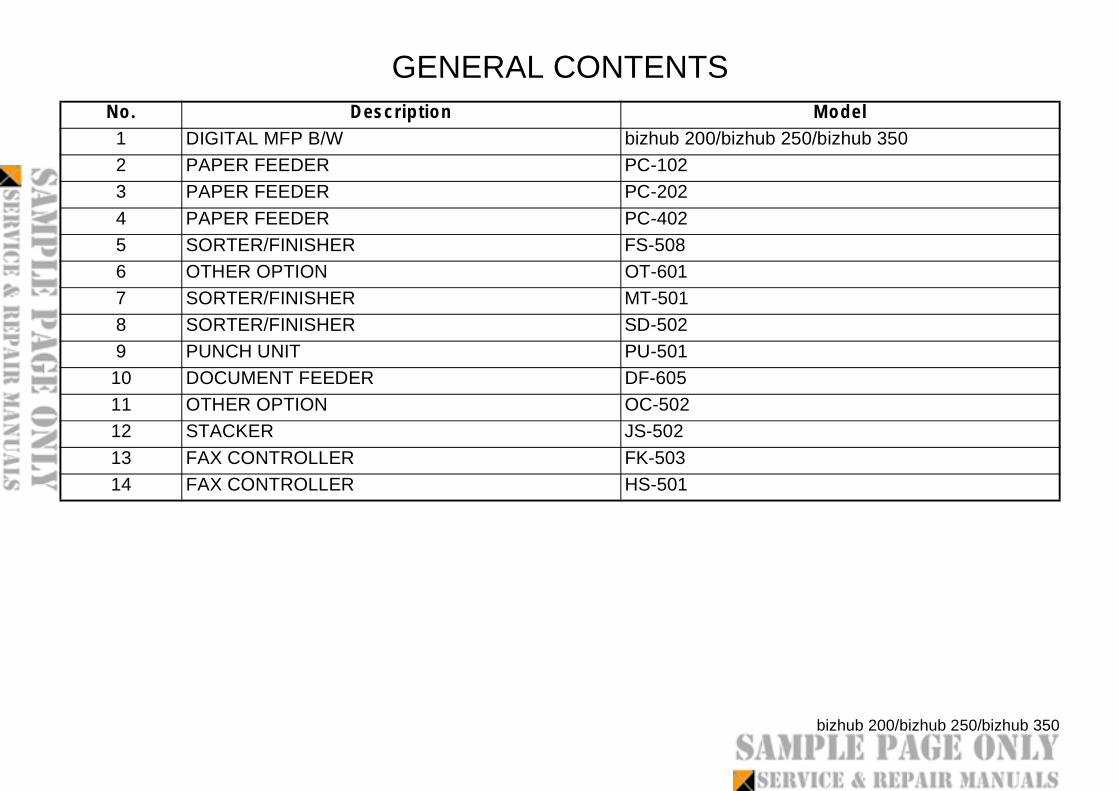
GENERAL CONTENTSNo. Description1 DIGITAL MFP B/W bizhub 200/b2 PAPER FEEDER PC-1023 PAPER FEEDER PC-2024 PAPER FEEDER PC-4025 SORTER/FINISHER FS-5086 OTHER OPTION OT-6017 SORTER/FINISHER MT-5018 SORTER/FINISHER SD-5029 PUNCH UNIT PU-50110 DOCUMENT FEEDER DF-60511 OTHER OPTION OC-50212 STACKER JS-50213 FAX CONTROLLER FK-50314 FAX CONTROLLER HS-501

SECURITY FUNCTIONSERVICE MANUAL
2006.092006.09Ver. 1.04Ver. 1.04
This Service Manual (Ver. 1.04) describes bizhub 200/bizhub 250
/bizhub 350/ineo 250/ineo 350 (Ver. 1) Multi Function Peripheral
Control Software (MFP: 4040-0100-G10-25-000).


