Nokia Lumia 1520RM-937, RM-938, RM-939, RM-940 (AT&T)Version 1.0
Disassembly steps
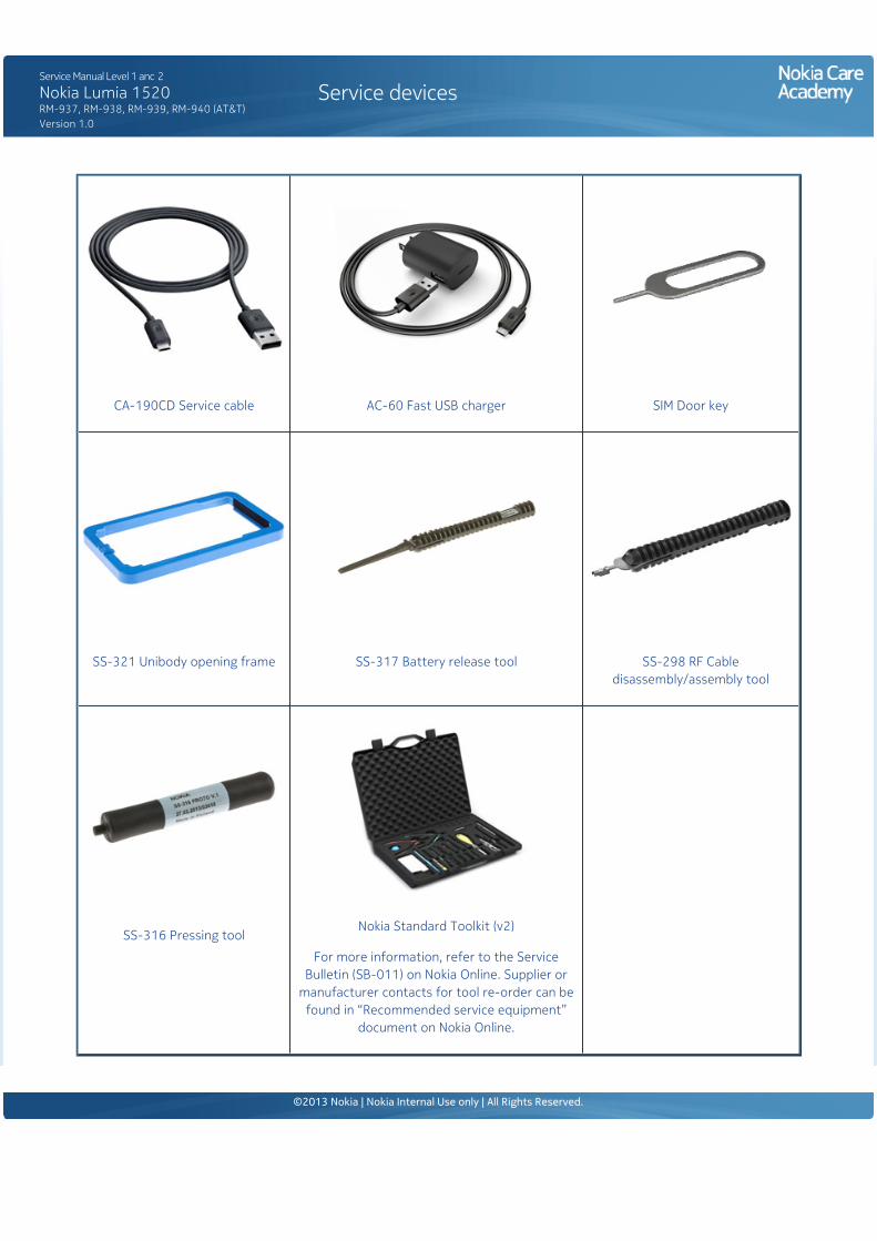
1) For disassembling you need the Nokia Standard toolkit version 2. You will also need the SIM door key,the unibody opening frame SS-321, the RF cable disassembly/assembly tool SS-298 and the batteryrelease tool SS-317.
Note that the device used in this disassembly procedure is RM-940.
2) The power must be off during the disassembly procedure.
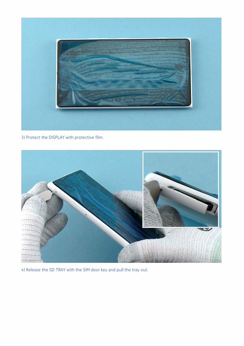
3) Protect the DISPLAY with protective film.
4) Release the SD TRAY with the SIM door key and pull the tray out.
5) Release the SIM TRAY with the SIM door key and pull the tray out.
6) Use tweezers to remove the IMEI LABEL. Store the IMEI LABEL on non-stick surface so it can be re-assembled.
7) Unscrew the TORX+ size 2 LOCKING RAIL SCREW.
8) Use the unibody opening frame SS-321 to separate the DISPLAY ASSEMBLY and the UNIBODYASSEMBLY. First place the bottom end of the device into the frame.
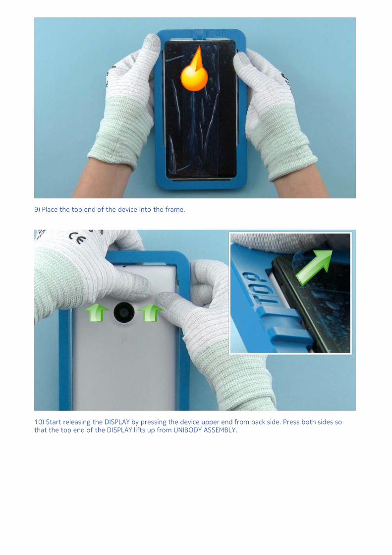
9) Place the top end of the device into the frame.
10) Start releasing the DISPLAY by pressing the device upper end from back side. Press both sides sothat the top end of the DISPLAY lifts up from UNIBODY ASSEMBLY.
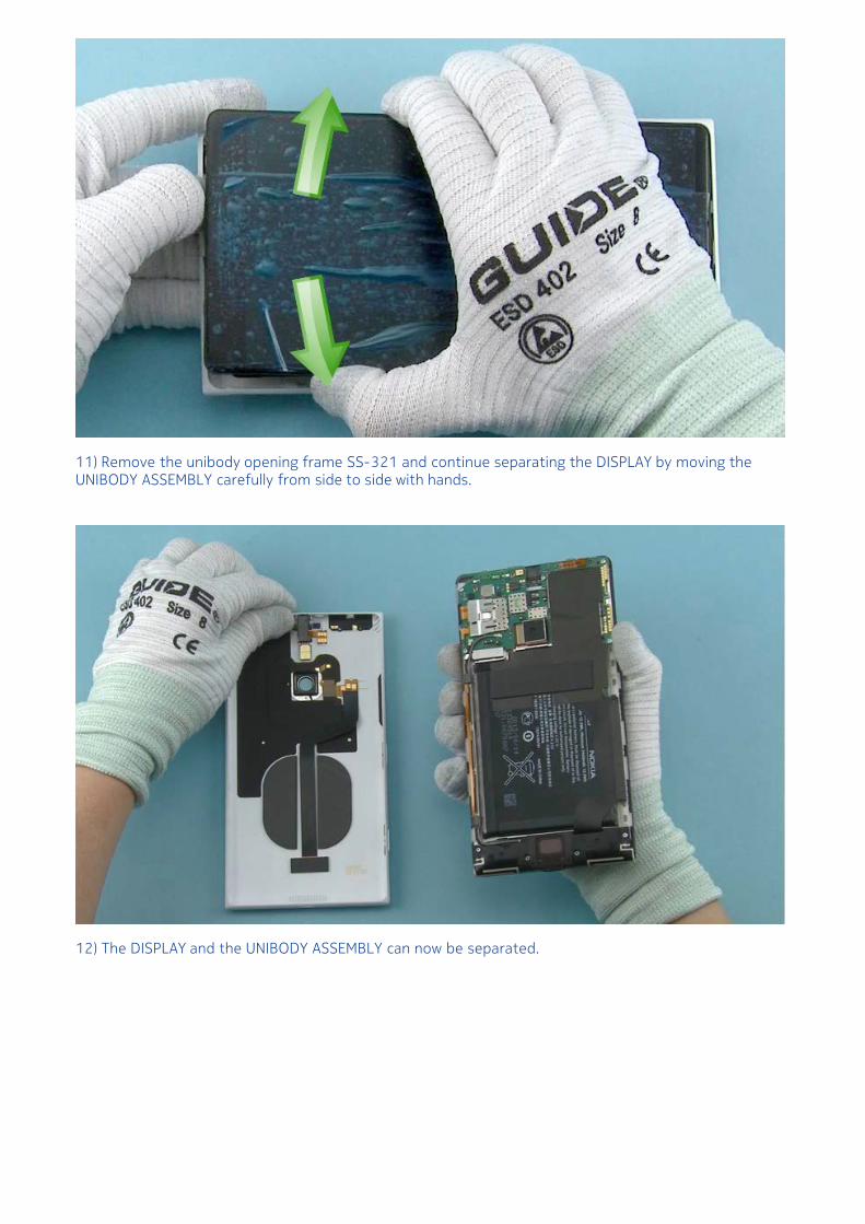
11) Remove the unibody opening frame SS-321 and continue separating the DISPLAY by moving theUNIBODY ASSEMBLY carefully from side to side with hands.
12) The DISPLAY and the UNIBODY ASSEMBLY can now be separated.
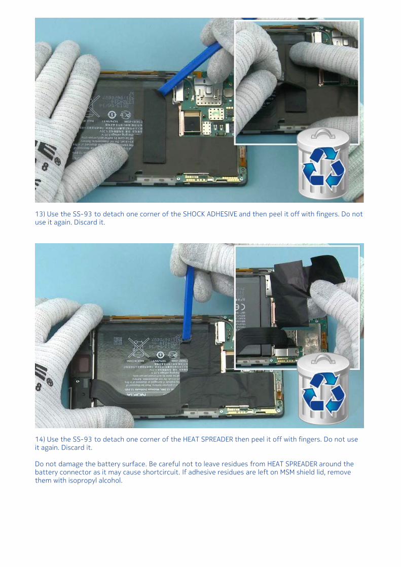
13) Use the SS-93 to detach one corner of the SHOCK ADHESIVE and then peel it off with fingers. Do notuse it again. Discard it.
14) Use the SS-93 to detach one corner of the HEAT SPREADER then peel it off with fingers. Do not useit again. Discard it.
Do not damage the battery surface. Be careful not to leave residues from HEAT SPREADER around thebattery connector as it may cause shortcircuit. If adhesive residues are left on MSM shield lid, removethem with isopropyl alcohol.
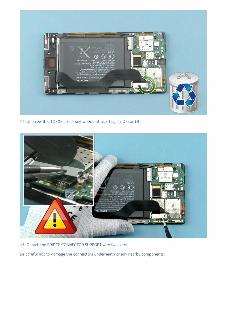
15) Unscrew this TORX+ size 4 screw. Do not use it again. Discard it.
16) Detach the BRIDGE CONNECTOR SUPPORT with tweezers.
Be careful not to damage the connectors underneath or any nearby components.
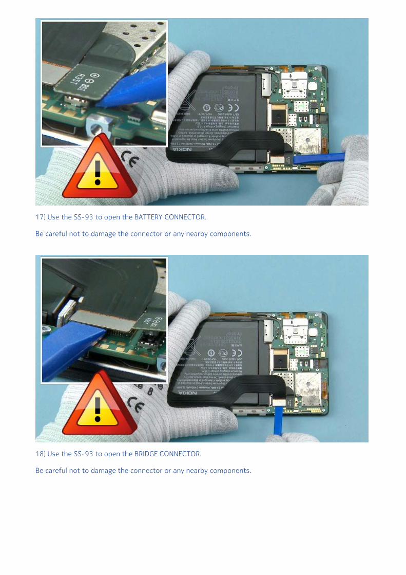
17) Use the SS-93 to open the BATTERY CONNECTOR.
Be careful not to damage the connector or any nearby components.
18) Use the SS-93 to open the BRIDGE CONNECTOR.
Be careful not to damage the connector or any nearby components.
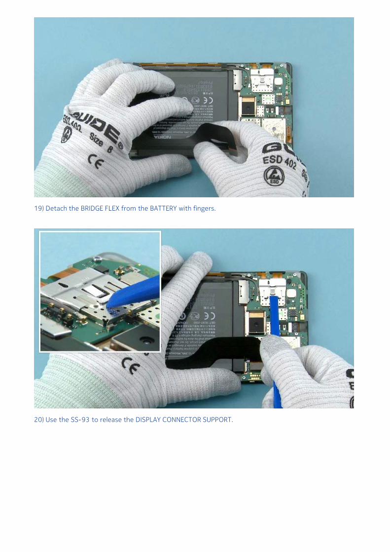
19) Detach the BRIDGE FLEX from the BATTERY with fingers.
20) Use the SS-93 to release the DISPLAY CONNECTOR SUPPORT.
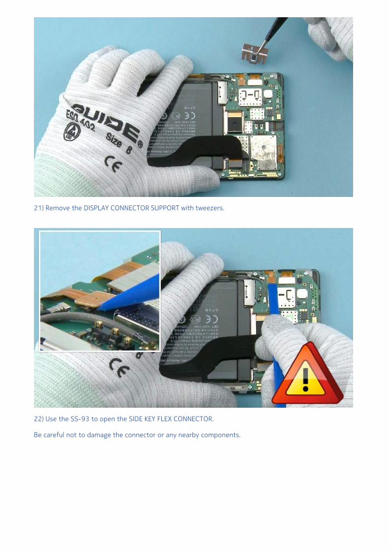
21) Remove the DISPLAY CONNECTOR SUPPORT with tweezers.
22) Use the SS-93 to open the SIDE KEY FLEX CONNECTOR.
Be careful not to damage the connector or any nearby components.
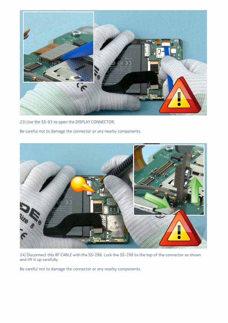
23) Use the SS-93 to open the DISPLAY CONNECTOR.
Be careful not to damage the connector or any nearby components.
24) Disconnect this RF CABLE with the SS-298. Lock the SS-298 to the top of the connector as shownand lift it up carefully.
Be careful not to damage the connector or any nearby components.
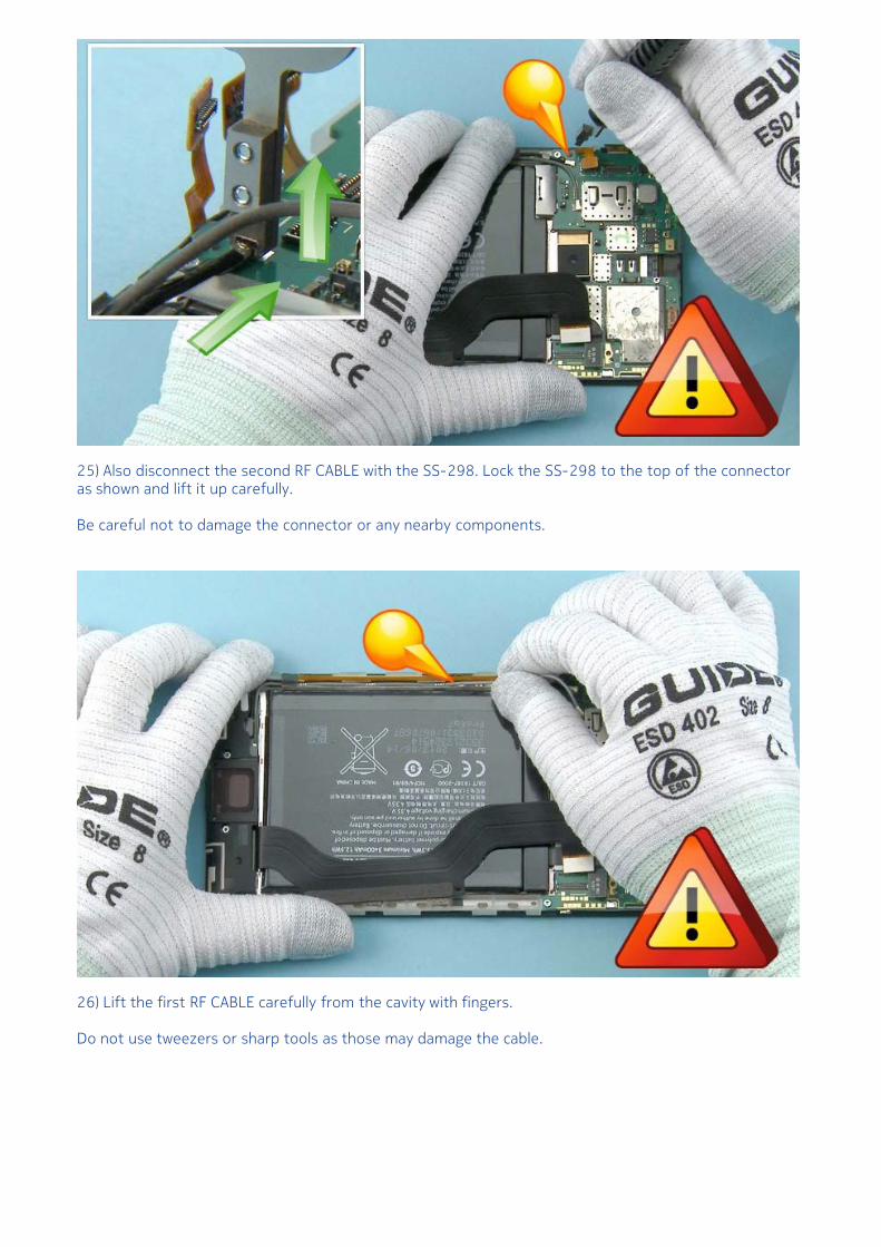
25) Also disconnect the second RF CABLE with the SS-298. Lock the SS-298 to the top of the connectoras shown and lift it up carefully.
Be careful not to damage the connector or any nearby components.
26) Lift the first RF CABLE carefully from the cavity with fingers.
Do not use tweezers or sharp tools as those may damage the cable.
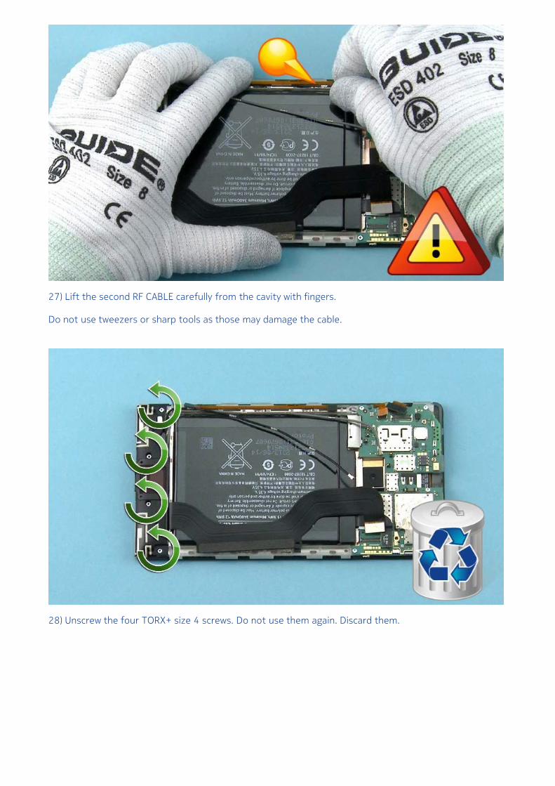
27) Lift the second RF CABLE carefully from the cavity with fingers.
Do not use tweezers or sharp tools as those may damage the cable.
28) Unscrew the four TORX+ size 4 screws. Do not use them again. Discard them.
29) Separate the IHF ASSEMBLY.
30) Use the SS-93 to carefully detach the BOTTOM MODULE from the IHF ANTENNA. Lever the BOTTOMMODULE from both ends to loosen the adhesive.
Be careful not to damage the components underneath the BOTTOM MODULE.
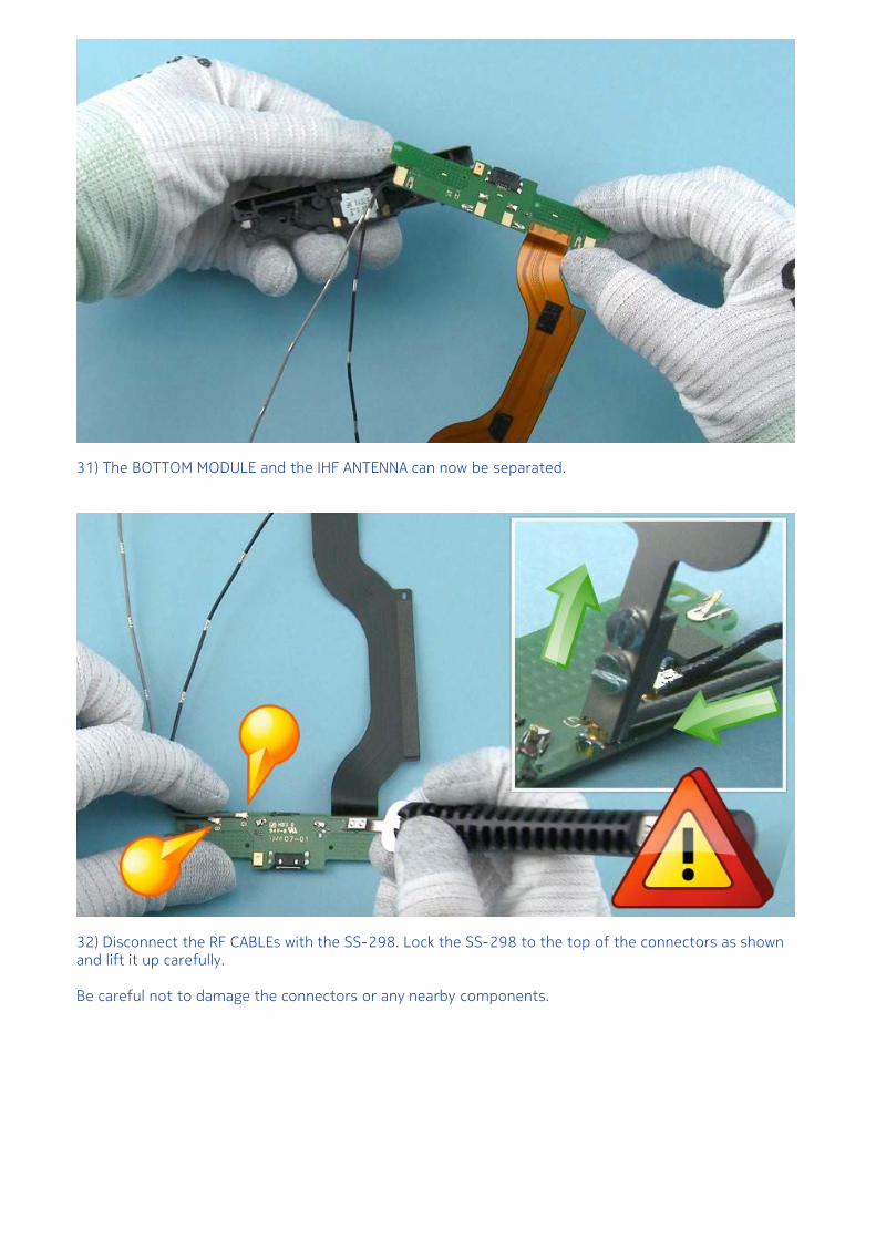
31) The BOTTOM MODULE and the IHF ANTENNA can now be separated.
32) Disconnect the RF CABLEs with the SS-298. Lock the SS-298 to the top of the connectors as shownand lift it up carefully.
Be careful not to damage the connectors or any nearby components.
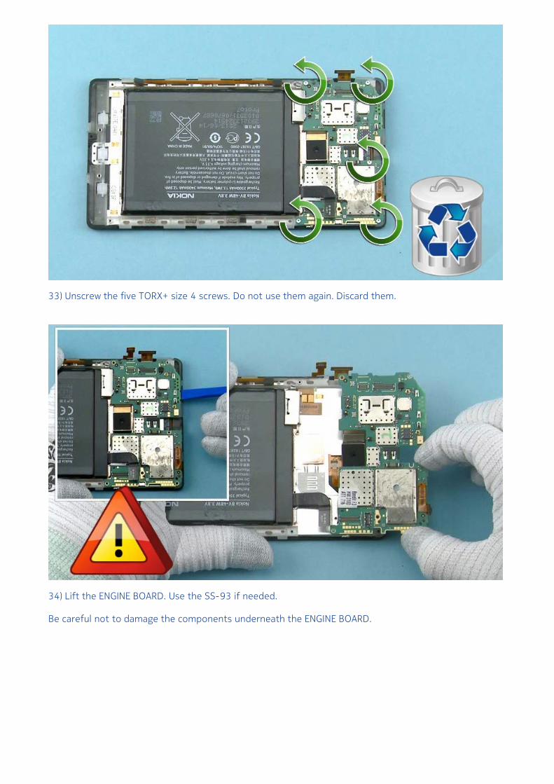
33) Unscrew the five TORX+ size 4 screws. Do not use them again. Discard them.
34) Lift the ENGINE BOARD. Use the SS-93 if needed.
Be careful not to damage the components underneath the ENGINE BOARD.
35) Use the SS-93 to open the CAMERA CONNECTOR.
Be careful not to damage the connector or any nearby components.
36) Remove the CAMERA with tweezers.
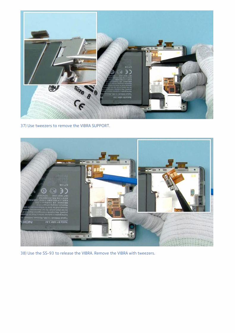
37) Use tweezers to remove the VIBRA SUPPORT.
38) Use the SS-93 to release the VIBRA. Remove the VIBRA with tweezers.
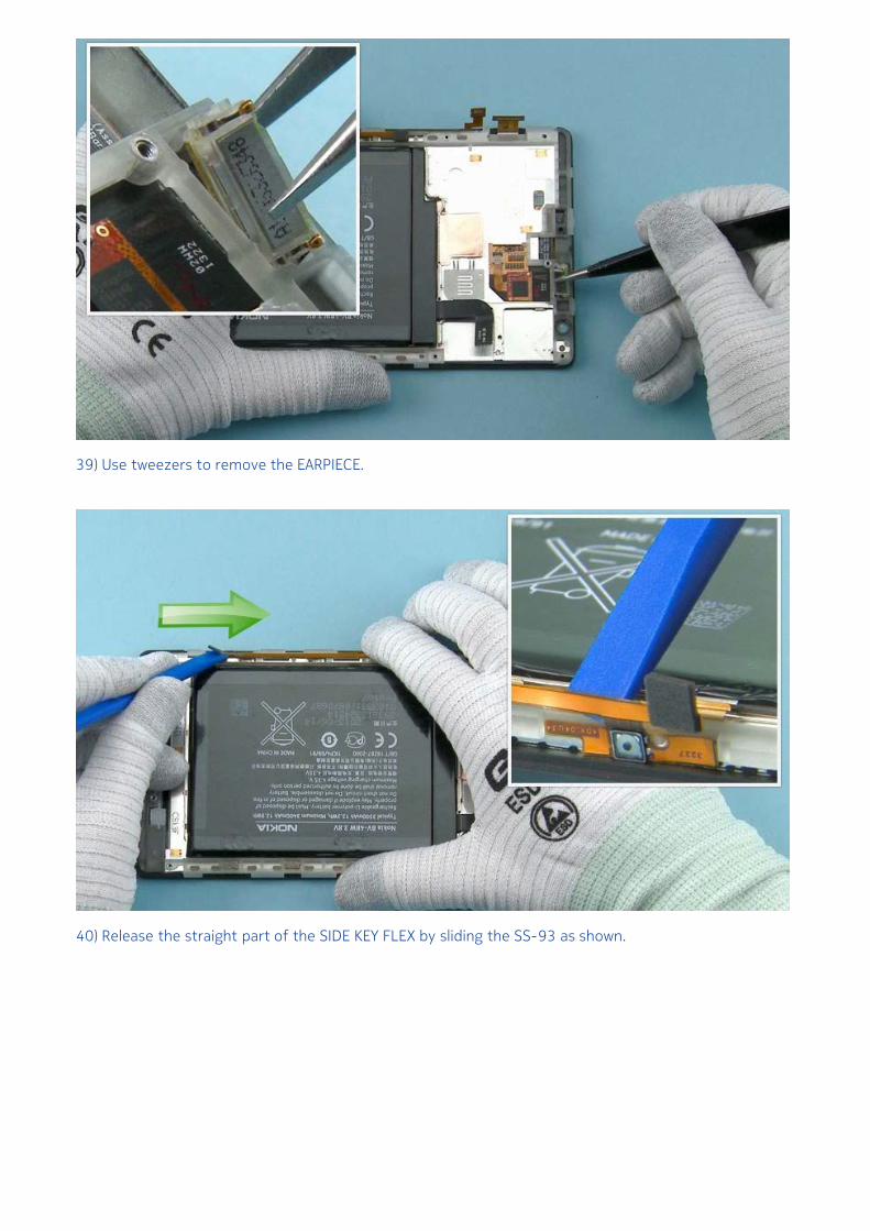
39) Use tweezers to remove the EARPIECE.
40) Release the straight part of the SIDE KEY FLEX by sliding the SS-93 as shown.
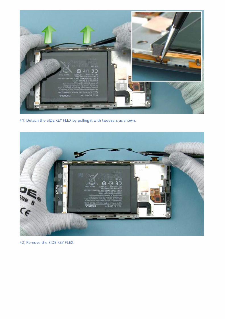
41) Detach the SIDE KEY FLEX by pulling it with tweezers as shown.
42) Remove the SIDE KEY FLEX.
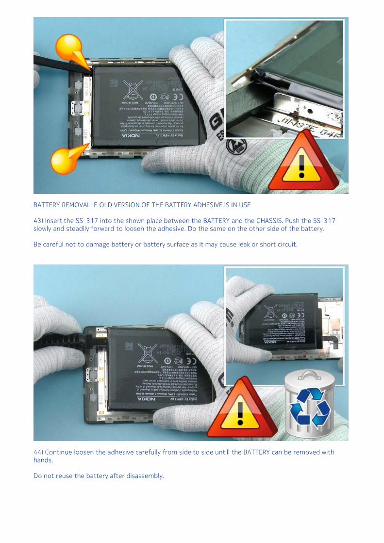
BATTERY REMOVAL IF OLD VERSION OF THE BATTERY ADHESIVE IS IN USE
43) Insert the SS-317 into the shown place between the BATTERY and the CHASSIS. Push the SS-317slowly and steadily forward to loosen the adhesive. Do the same on the other side of the battery.
Be careful not to damage battery or battery surface as it may cause leak or short circuit.
44) Continue loosen the adhesive carefully from side to side untill the BATTERY can be removed withhands.
Do not reuse the battery after disassembly.
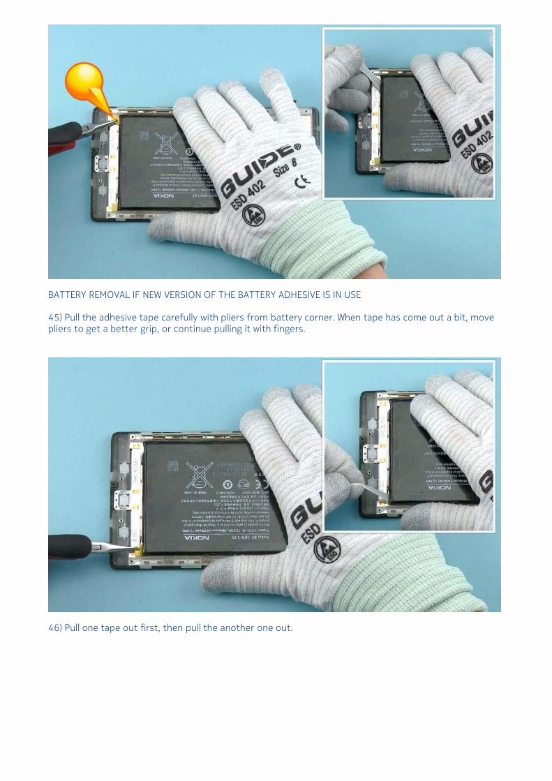
BATTERY REMOVAL IF NEW VERSION OF THE BATTERY ADHESIVE IS IN USE
45) Pull the adhesive tape carefully with pliers from battery corner. When tape has come out a bit, movepliers to get a better grip, or continue pulling it with fingers.
46) Pull one tape out first, then pull the another one out.
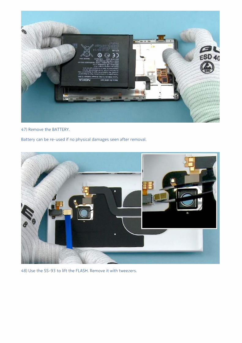
47) Remove the BATTERY.
Battery can be re-used if no physical damages seen after removal.
48) Use the SS-93 to lift the FLASH. Remove it with tweezers.
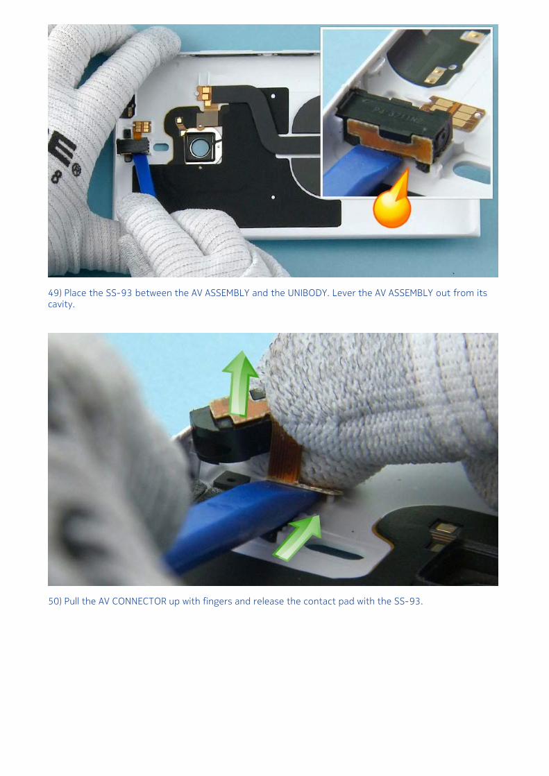
49) Place the SS-93 between the AV ASSEMBLY and the UNIBODY. Lever the AV ASSEMBLY out from itscavity.
50) Pull the AV CONNECTOR up with fingers and release the contact pad with the SS-93.
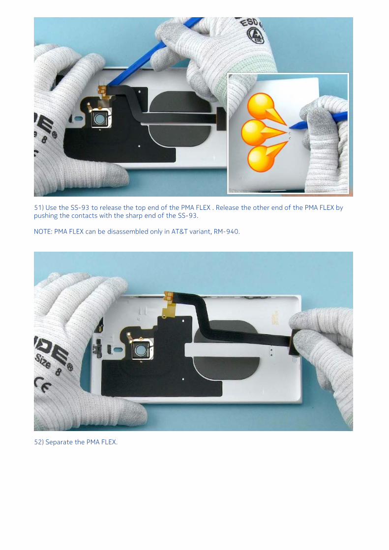
51) Use the SS-93 to release the top end of the PMA FLEX . Release the other end of the PMA FLEX bypushing the contacts with the sharp end of the SS-93.
NOTE: PMA FLEX can be disassembled only in AT&T variant, RM-940.
52) Separate the PMA FLEX.
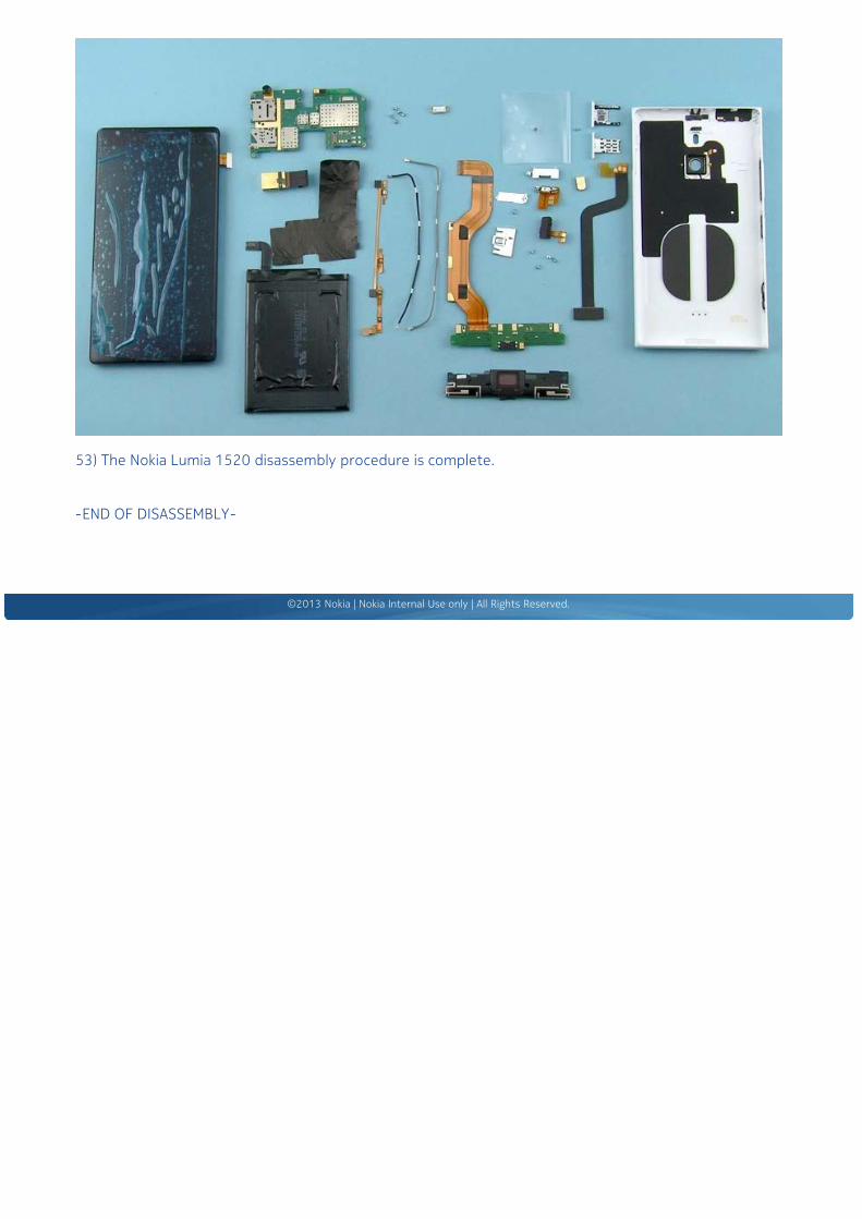
53) The Nokia Lumia 1520 disassembly procedure is complete.
Nokia Lumia 1520RM-937, RM-938, RM-939, RM-940 (AT&T)Version 1.0
Assembly steps
1) For assembling you need the Nokia Standard toolkit version 2. You will also need the RF cabledisassembly/assembly tool SS-298 and the SS-316 pressing tool.
2) Use tweezers to peel off the two protective films from the PMA FLEX.
NOTE: PMA FLEX can be assembled only in AT&T variant, RM-940.
3) Place the PMA FLEX into the UNIBODY MODULE. Use the shown guidings when aligning the flex. Pressgently to activate the adhesive on both ends.
4) Use tweezers to remove the protective film from the AV CONNECTOR. Place the AV CONNECTOR intoits cavity with tweezers.
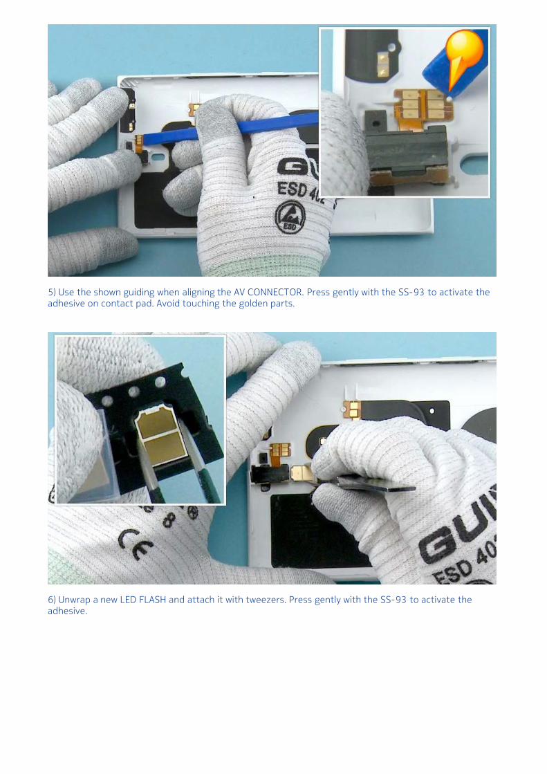
5) Use the shown guiding when aligning the AV CONNECTOR. Press gently with the SS-93 to activate theadhesive on contact pad. Avoid touching the golden parts.
6) Unwrap a new LED FLASH and attach it with tweezers. Press gently with the SS-93 to activate theadhesive.
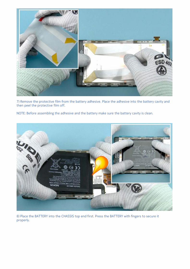
7) Remove the protective film from the battery adhesive. Place the adhesive into the battery cavity andthen peel the protective film off.
NOTE: Before assembling the adhesive and the battery make sure the battery cavity is clean.
8) Place the BATTERY into the CHASSIS top end first. Press the BATTERY with fingers to secure itproperly.
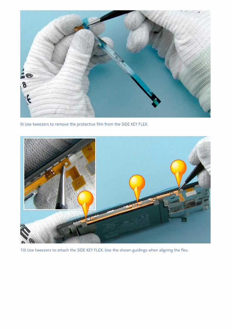
9) Use tweezers to remove the protective film from the SIDE KEY FLEX.
10) Use tweezers to attach the SIDE KEY FLEX. Use the shown guidings when aligning the flex.
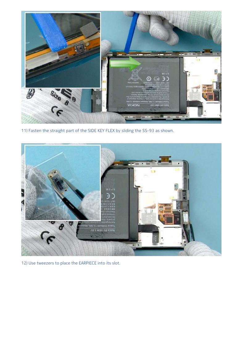
11) Fasten the straight part of the SIDE KEY FLEX by sliding the SS-93 as shown.
12) Use tweezers to place the EARPIECE into its slot.
13) Use tweezers to remove the protective film from the VIBRA. Align the VIBRA with tweezers.
14) Press gently with the SS-93 to activate the adhesive.
15) Use tweezers to assemble the VIBRA SUPPORT. Align the shown side first.
16) Use the SS-93 to connect the CAMERA CONNECTOR.
Be careful not to damage the connector or any nearby components.
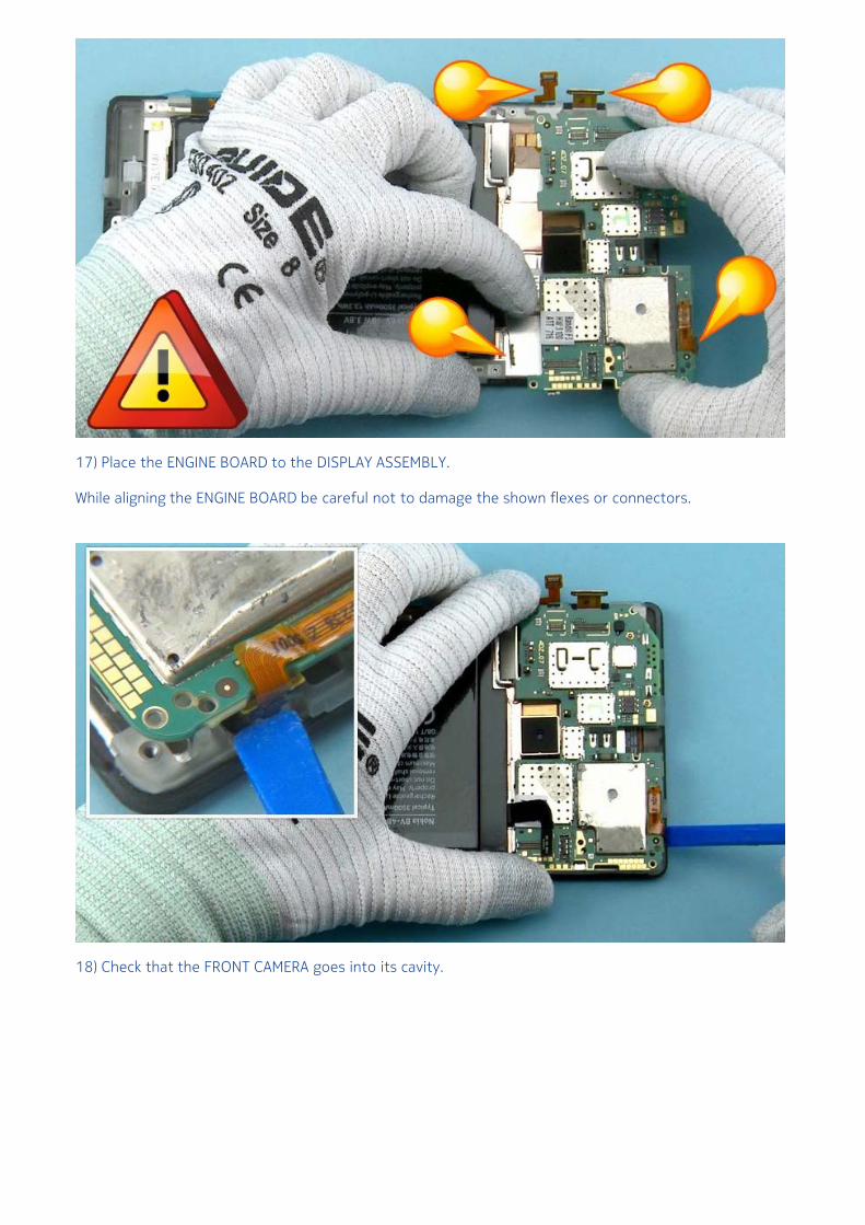
17) Place the ENGINE BOARD to the DISPLAY ASSEMBLY.
While aligning the ENGINE BOARD be careful not to damage the shown flexes or connectors.
18) Check that the FRONT CAMERA goes into its cavity.
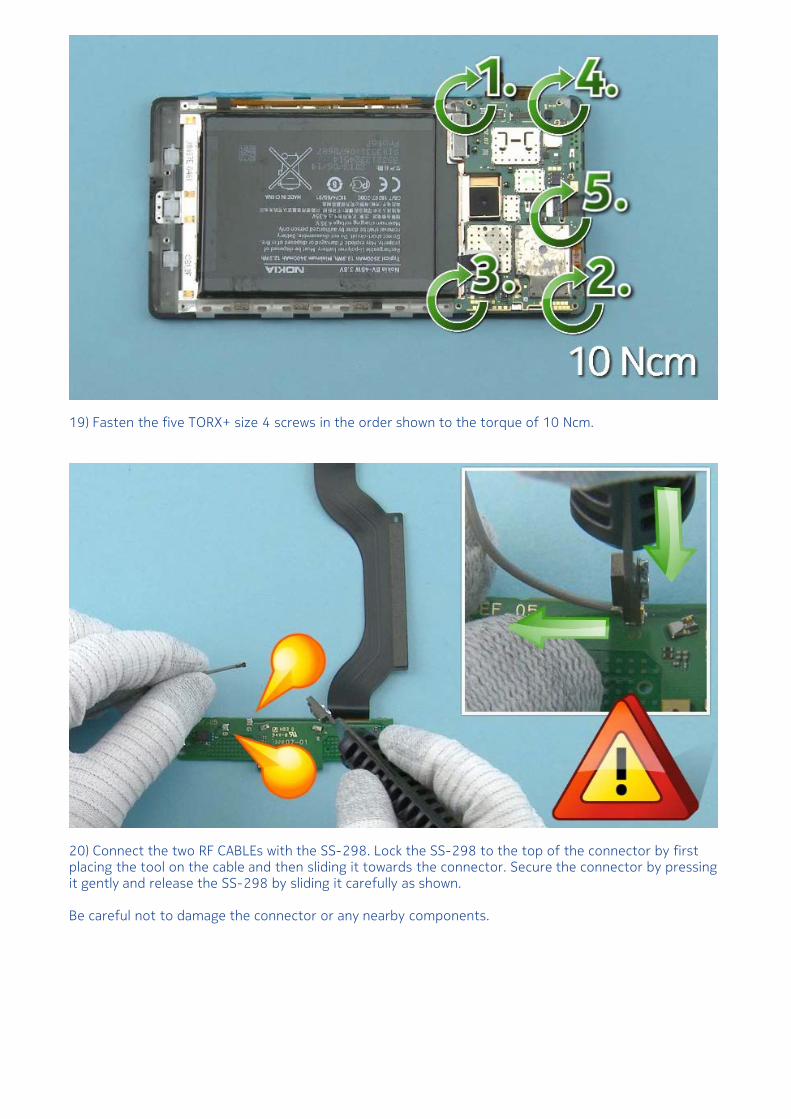
19) Fasten the five TORX+ size 4 screws in the order shown to the torque of 10 Ncm.
20) Connect the two RF CABLEs with the SS-298. Lock the SS-298 to the top of the connector by firstplacing the tool on the cable and then sliding it towards the connector. Secure the connector by pressingit gently and release the SS-298 by sliding it carefully as shown.
Be careful not to damage the connector or any nearby components.
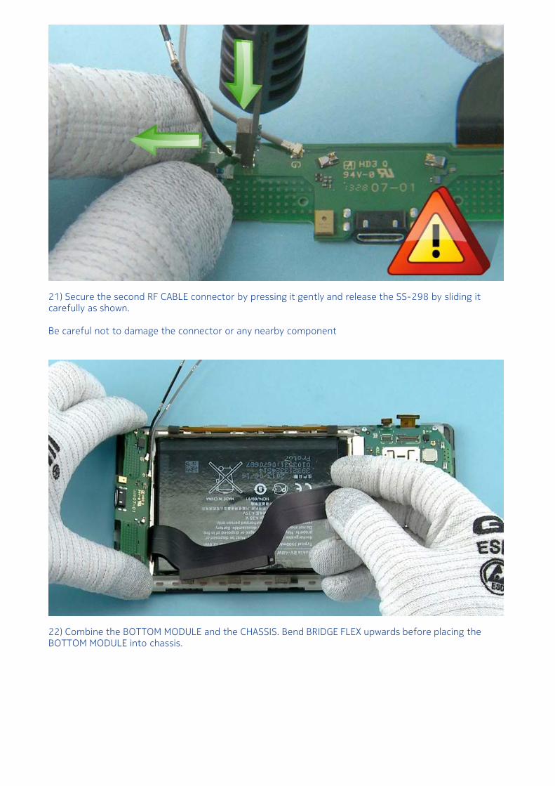
21) Secure the second RF CABLE connector by pressing it gently and release the SS-298 by sliding itcarefully as shown.
Be careful not to damage the connector or any nearby component
22) Combine the BOTTOM MODULE and the CHASSIS. Bend BRIDGE FLEX upwards before placing theBOTTOM MODULE into chassis.
23) Peel off this protective film from the IHF ASSEMBLY. Place the IHF ASSEMBLY on top of the BOTTOMMODULE.
24) Fasten the four TORX+ size 4 screws in the order shown to the torque of 10 Ncm.
25) Use tweezers to remove the second protective film from the IHF ASSEMBLY. Use the SS-93 to bendthe gasket around the USB.
26) Use the SS-298 to connect the black RF CABLE. Secure the connector by pressing it gently andrelease the SS-298 by sliding it carefully as shown.
Be careful not to damage the connector or any nearby components.
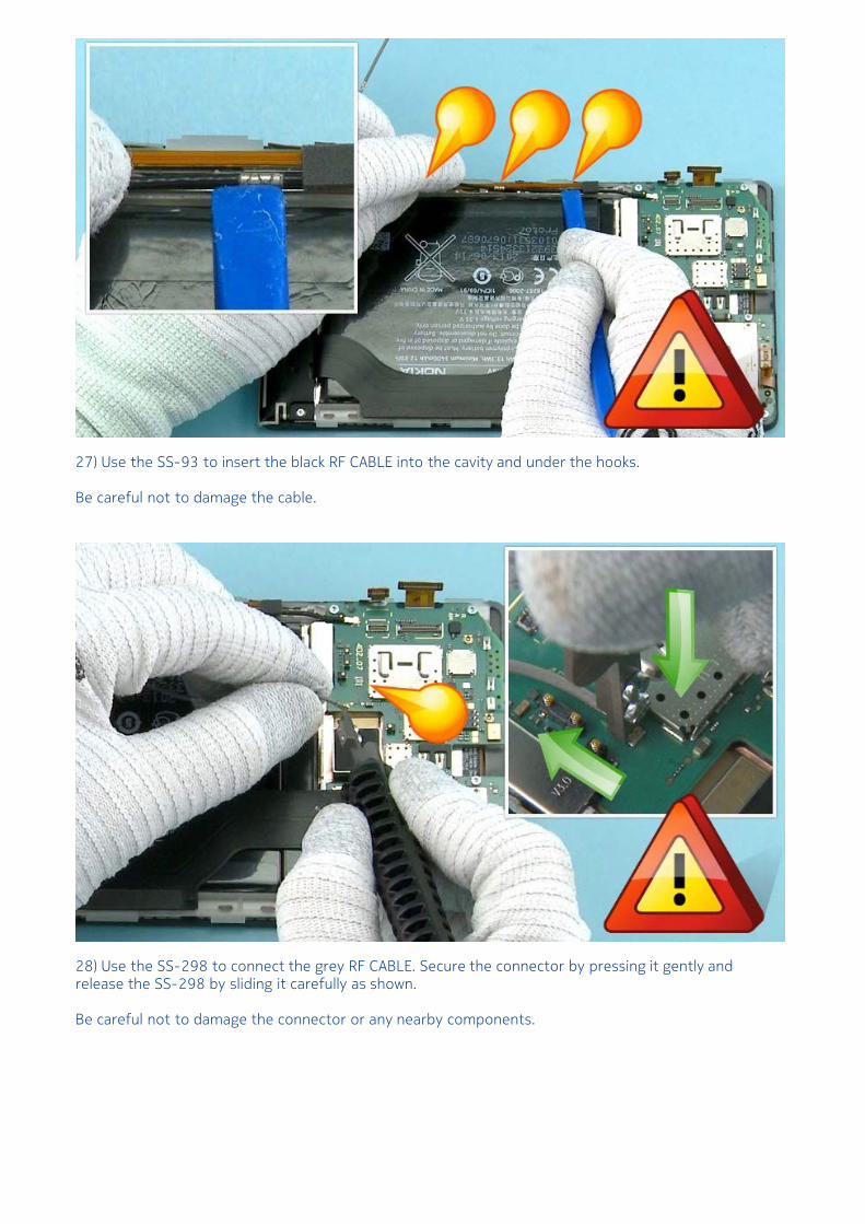
27) Use the SS-93 to insert the black RF CABLE into the cavity and under the hooks.
Be careful not to damage the cable.
28) Use the SS-298 to connect the grey RF CABLE. Secure the connector by pressing it gently andrelease the SS-298 by sliding it carefully as shown.
Be careful not to damage the connector or any nearby components.
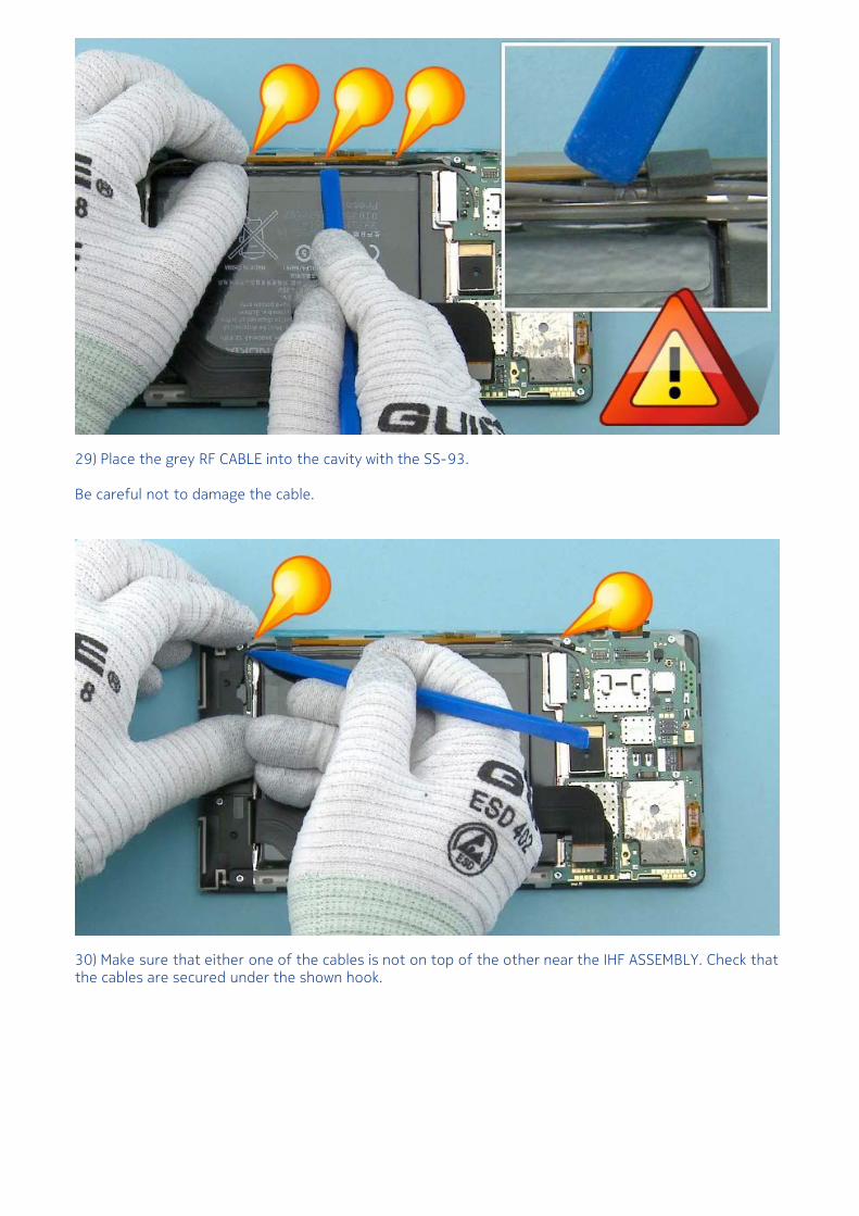
29) Place the grey RF CABLE into the cavity with the SS-93.
Be careful not to damage the cable.
30) Make sure that either one of the cables is not on top of the other near the IHF ASSEMBLY. Check thatthe cables are secured under the shown hook.
31) Use the SS-93 to connect the DISPLAY CONNECTOR.
Be careful not to damage the connector or any nearby components.
32) Use the SS-93 to connect the SIDE KEY FLEX CONNECTOR.
Be careful not to damage the connector or any nearby components.
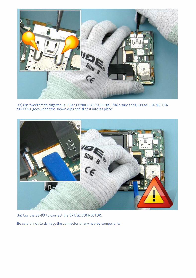
33) Use tweezers to align the DISPLAY CONNECTOR SUPPORT. Make sure the DISPLAY CONNECTORSUPPORT goes under the shown clips and slide it into its place.
34) Use the SS-93 to connect the BRIDGE CONNECTOR.
Be careful not to damage the connector or any nearby components.
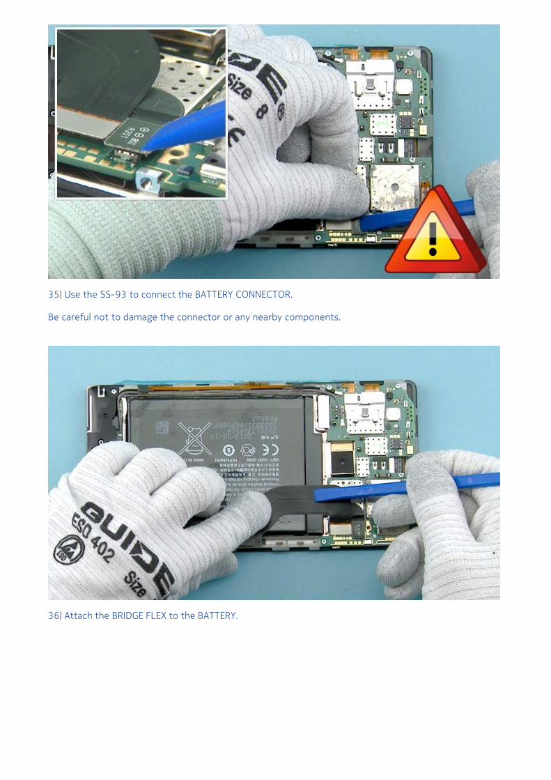
35) Use the SS-93 to connect the BATTERY CONNECTOR.
Be careful not to damage the connector or any nearby components.
36) Attach the BRIDGE FLEX to the BATTERY.
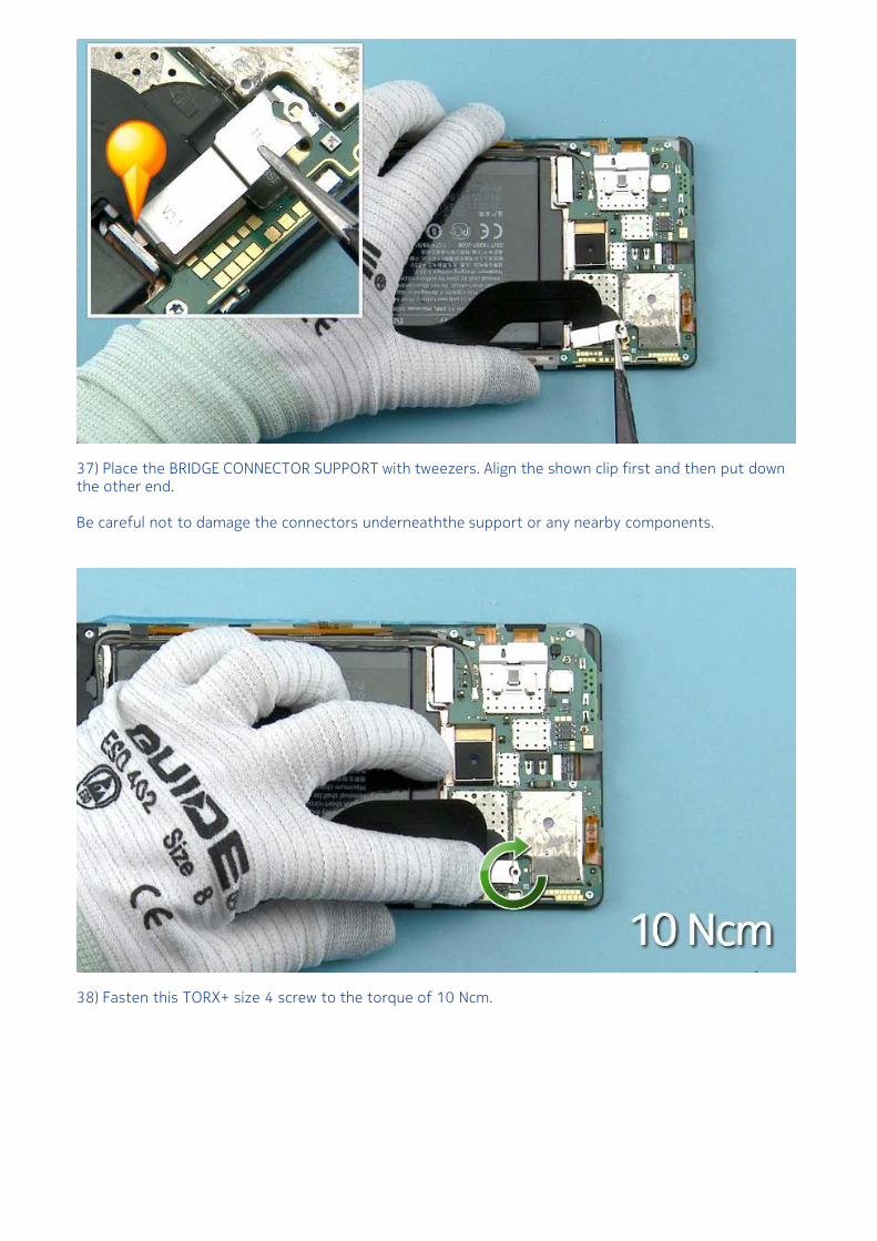
37) Place the BRIDGE CONNECTOR SUPPORT with tweezers. Align the shown clip first and then put downthe other end.
Be careful not to damage the connectors underneaththe support or any nearby components.
38) Fasten this TORX+ size 4 screw to the torque of 10 Ncm.
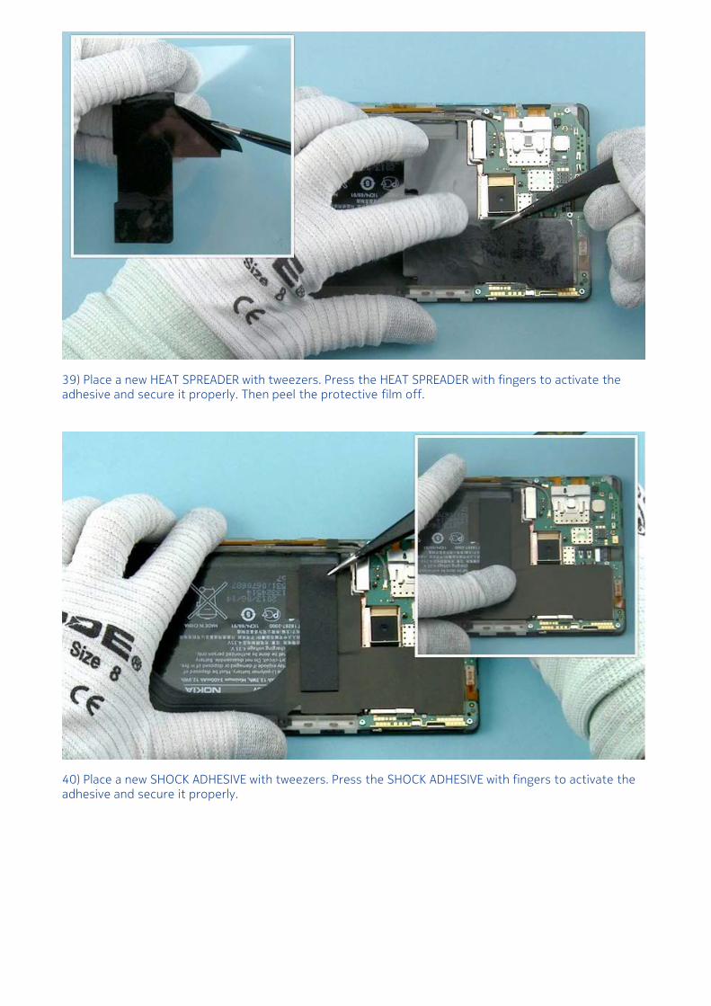
39) Place a new HEAT SPREADER with tweezers. Press the HEAT SPREADER with fingers to activate theadhesive and secure it properly. Then peel the protective film off.
40) Place a new SHOCK ADHESIVE with tweezers. Press the SHOCK ADHESIVE with fingers to activate theadhesive and secure it properly.
41) First align the bottom end of the WINDOW ASSEMBLY to the UNIBODY ASSEMBLY and slide theWINDOW ASSEMBLY in low angle into its place.
42) Then place the other end. Hold the device in hands and press slightly to attach the WINDOWASSEMBLY correctly.
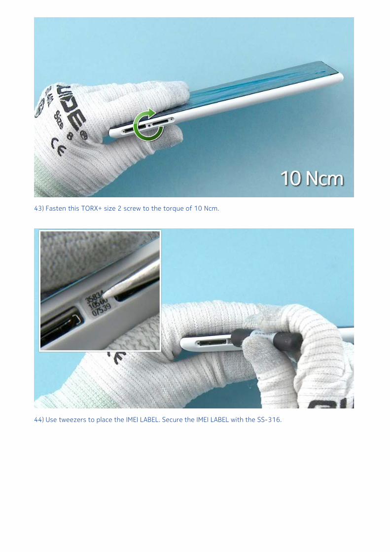
43) Fasten this TORX+ size 2 screw to the torque of 10 Ncm.
44) Use tweezers to place the IMEI LABEL. Secure the IMEI LABEL with the SS-316.
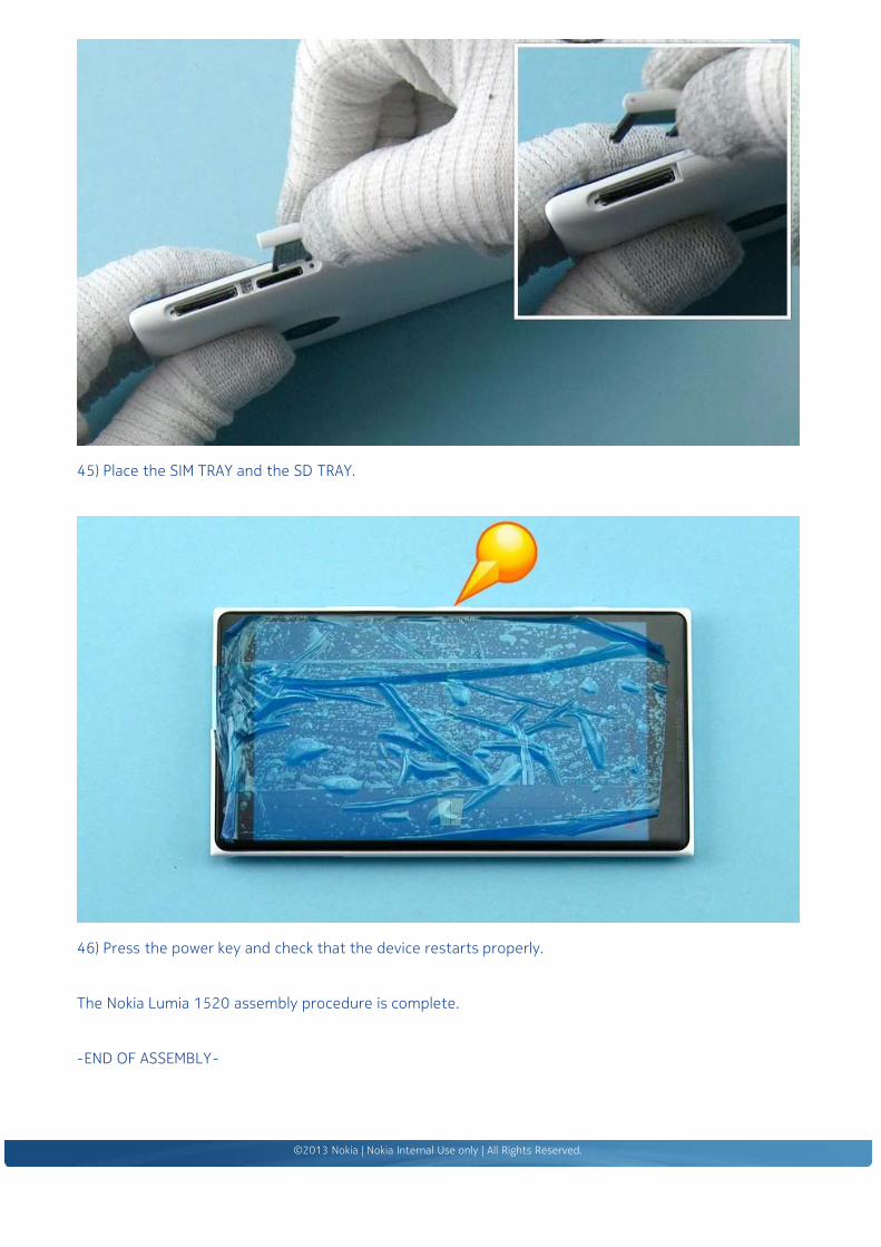
45) Place the SIM TRAY and the SD TRAY.
46) Press the power key and check that the device restarts properly.
The Nokia Lumia 1520 assembly procedure is complete.
Nokia Lumia 1520RM-937, RM-938, RM-939, RM-940 (AT&T)Version 1.0
Phone reset
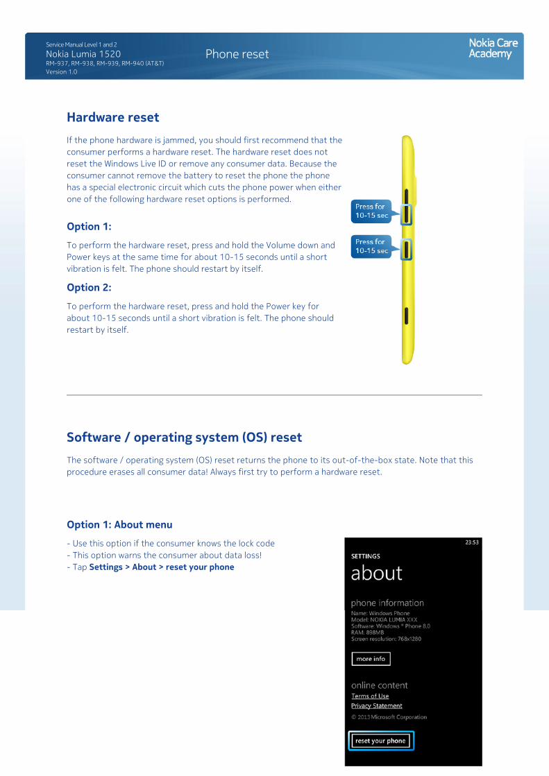
Hardware resetIf the phone hardware is jammed, you should first recommend that the consumer performs a hardware reset. The hardware reset does not reset the Windows Live ID or remove any consumer data. Because the consumer cannot remove the battery to reset the phone the phone has a special electronic circuit which cuts the phone power when either one of the following hardware reset options is performed.
Option 1:
To perform the hardware reset, press and hold the Volume down and Power keys at the same time for about 10-15 seconds until a short vibration is felt. The phone should restart by itself.
Option 2:
To perform the hardware reset, press and hold the Power key for about 10-15 seconds until a short vibration is felt. The phone should restart by itself.
Software / operating system (OS) resetThe software / operating system (OS) reset returns the phone to its out-of-the-box state. Note that this procedure erases all consumer data! Always first try to perform a hardware reset.
Option 1: About menu
- Use this option if the consumer knows the lock code - This option warns the consumer about data loss! - Tap Settings > About > reset your phone
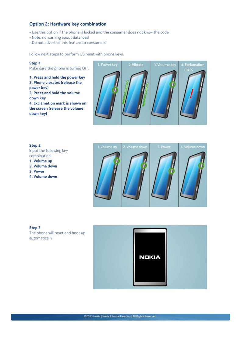
Option 2: Hardware key combination
- Use this option if the phone is locked and the consumer does not know the code- Note: no warning about data loss!- Do not advertise this feature to consumers!
Follow next steps to perform OS reset with phone keys.
Step 1Make sure the phone is turned Off.
1. Press and hold the power key2. Phone vibrates (release the power key)3. Press and hold the volume down key4. Exclamation mark is shown on the screen (release the volume down key)
Step 2Input the following key combination:1. Volume up2. Volume down3. Power4. Volume down
Step 3The phone will reset and boot up automatically