Sleek and stylish unibody design Windows Phone 8 Operating System 4.3" IPS LCD display with Nokia ClearBlack technology6.7 Mpix main camera with f/1.9 aperture 1.3 Mpix front cameraBluetooth 3.0, NFC connectivity
Version 1.0
Exploded view Disassembly steps Disassembly video
Assembly steps Assembly video Solder components
Service devices Product controls and interfaces Service concept
1) For disassembling you need the Nokia Standard toolkit version 2. You will also need an AV plug and theSIM door key.
2) Protect the DISPLAY MODULE with protective film.
3) Insert the SIM door key to the small hole on the SD DOOR and press it gently. Remove the SD DOOR.
4) Insert the SIM door key to the small hole on the SIM DOOR and press it gently. Remove the SIM DOOR.
5) Unscrew the TORX+ size 2 screw. Do not use it again. Discard it.
6) To release the DISPLAY MODULE insert the SRT-6 to the top left corner of the device and slide to thedirection shown. Be careful not to damage the UNIBODY ASSEMBLY!
7) Push the top end of the UNIBODY ASSEMBLY to the direction shown to release the top part of theDISPLAY MODULE.
8) Release the left side of the UNIBODY ASSEMBLY by sliding the SRT-6 to the direction shown. Becareful not to damage the UNIBODY ASSEMBLY!
9) Release the four clips on the right side of the device with the SRT-6. Do not slide the SRT-6 as it mightdamage the SIDEKEY FLEX!
10) Lift the top end of the DISPLAY MODULE up first. The DISPLAY MODULE and the UNIBODY ASSEMBLYcan now be separated.
11) Use the AV plug to lever up the AV MODULE. Remove the AV MODULE.
12) Lift one corner of the BATTERY GASKET with the SS-93 and peel it off. Do not use it again. Discard it.
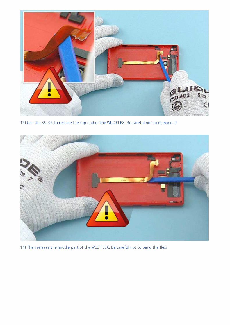
13) Use the SS-93 to release the top end of the WLC FLEX. Be careful not to damage it!
14) Then release the middle part of the WLC FLEX. Be careful not to bend the flex!
15) Carefully release the bottom end of the WLC FLEX and remove it. Be careful not to damage the flex!
16) Use the SS-93 to release the FLASH LED. Remove it with tweezers.
17) Open the BATTERY connector with the SS-93. Be careful not to damage the connector or anycomponents nearby!
18) Use the SS-93 to release the top parts of the HEATSPREADER. Be careful not to damage theBATTERY connector!
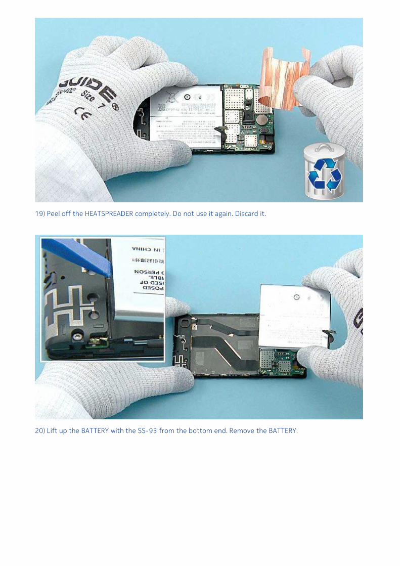
19) Peel off the HEATSPREADER completely. Do not use it again. Discard it.
20) Lift up the BATTERY with the SS-93 from the bottom end. Remove the BATTERY.
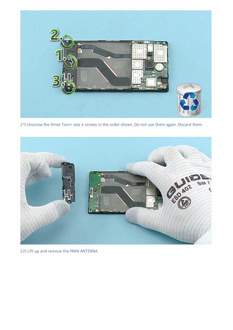
21) Unscrew the three Torx+ size 4 screws in the order shown. Do not use them again. Discard them.
22) Lift up and remove the MAIN ANTENNA.
23) Use the dental tool to lever up the IHF SPEAKER. Be careful not to injure yourself with the sharp endof the dental tool. The IHF SPEAKER is not reusable. Discard it.
24) Release also the IHF SPEAKER GASKET with the dental tool. Discard it.
25) Use the SRT-6 to release the top end of the RF COAX CABLE. Be very careful when opening theconnector! Be also careful not to damage any components nearby!
26) Unscrew the four Torx+ size 4 screws in the order shown. Remove the screws with tweezers to avoiddamaging the components on the ENGINE BOARD! Do not use these screws again. Discard them.
27) Use the SS-93 to open the SIDEKEY FLEX connector. Be careful not to damage the connector or anycomponents nearby!
28) Turn the ENGINE BOARD over as shown. Open the DISPLAY connector with the SS-93. Be careful notto damage the connector or any components nearby!
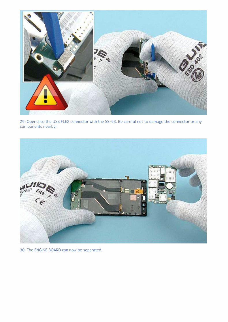
29) Open also the USB FLEX connector with the SS-93. Be careful not to damage the connector or anycomponents nearby!
30) The ENGINE BOARD can now be separated.
31) Open the FRONT CAMERA connector with the SS-93 and remove it. Be careful not to damage theconnector or any components nearby!
32) Open the CAMERA connector with the SS-93 and remove it. Be careful not to damage the connectoror any components nearby!
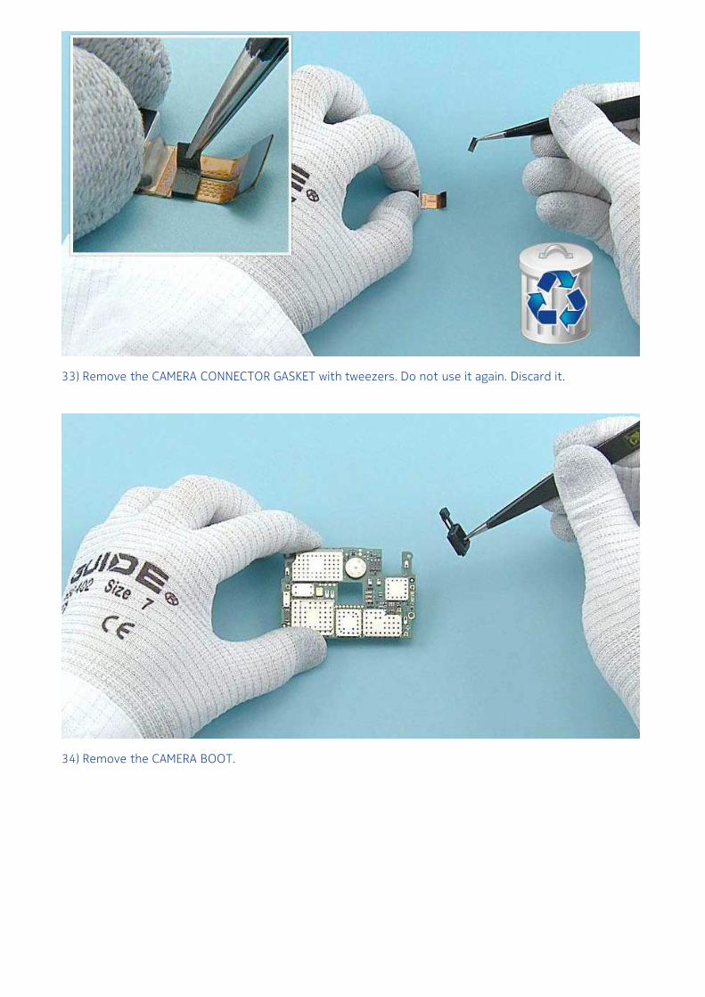
33) Remove the CAMERA CONNECTOR GASKET with tweezers. Do not use it again. Discard it.
34) Remove the CAMERA BOOT.
35) Release the IC GASKET with the dental tool. Be careful not to damage the ENGINE BOARD! Do not usethe IC GASKET again.
36) Lift up the RF COAX CABLE HOLDER with the RF COAX CABLE from the shown places.
37) Open the bottom end connector of the RF COAX CABLE with the SRT-6. Be very careful not todamage the connector or any components nearby! Remove the RF COAX CABLE and the RF COAX CABLEHOLDER.
38) Separate the RF COAX CABLE from the RF COAX CABLE HOLDER as shown.
39) Release the USB FLEX with the SS-93. Be careful not to damage the flex! Lift up and remove the USBFLEX.
40) Release the EARPIECE with the SS-93 and remove it with tweezers. Do not use it again. Discard it.
41) Remove the EARPIECE GASKET with the dental tool and discard it.
42) Remove the SIDEKEY FLEX with the SS-93. The SIDEKEY FLEX is not reusable. Discard it.
43) Remove the adhesive remains from the DISPLAY FRAME.
44) Use the dental tool to remove the FRONT CAMERA GASKET. Do not use it again. Discard it.
45) The Nokia Lumia 720 disassembly procedure is complete.
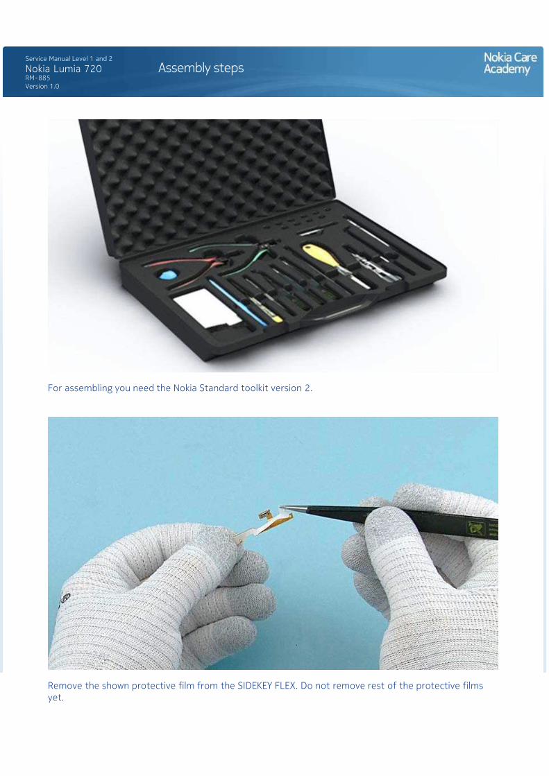
For assembling you need the Nokia Standard toolkit version 2.
Remove the shown protective film from the SIDEKEY FLEX. Do not remove rest of the protective filmsyet.
Place the SIDEKEY FLEX to the DISPLAY FRAME. Align the two shown SIDEKEY FLEX holes with the DISPLAYFRAME pins.
Remove the remaining protective films. Lower down the bottom end of the SIDEKEY FLEX and align itwith the shown pin.
Press the SIDEKEY FLEX for 5 seconds to activate the adhesive.
Remove the shown protective film from the EARPIECE GASKET.
Place the EARPIECE GASKET to the DISPLAY FRAME. Press the EARPIECE GASKET to activate the adhesive.Remove the remaining protective film.
Remove the EARPIECE from its package.
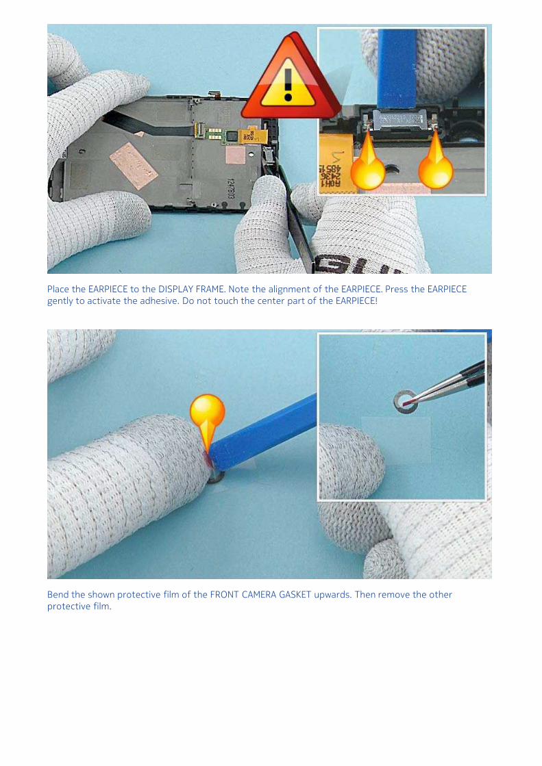
Place the EARPIECE to the DISPLAY FRAME. Note the alignment of the EARPIECE. Press the EARPIECEgently to activate the adhesive. Do not touch the center part of the EARPIECE!
Bend the shown protective film of the FRONT CAMERA GASKET upwards. Then remove the otherprotective film.
Place the FRONT CAMERA GASKET to the DISPLAY FRAME and press it to activate the adhesive. Removethe protective film.
Place the CAMERA BOOT to the ENGINE BOARD. Be careful not to damage any components on theENGINE BOARD.
Remove the IC GASKET protective film.
Place the IC GASKET to the ENGINE BOARD as shown.
Remove the CAMERA CONNECTOR GASKET protective film.
Place the CAMERA CONNECTOR GASKET and align it with the shown edge. Bend the CAMERA flex slightly.Be careful not to damage the CAMERA flex!
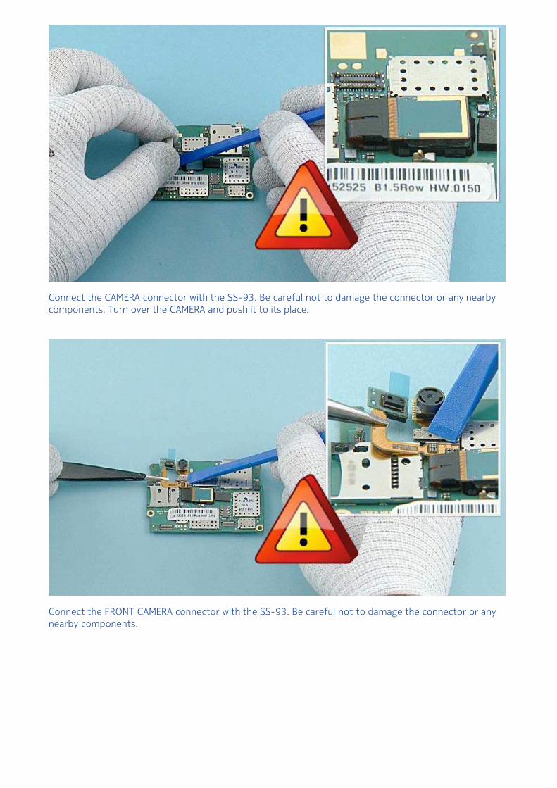
Connect the CAMERA connector with the SS-93. Be careful not to damage the connector or any nearbycomponents. Turn over the CAMERA and push it to its place.
Connect the FRONT CAMERA connector with the SS-93. Be careful not to damage the connector or anynearby components.
Place the USB FLEX to the DISPLAY FRAME. Make sure the two shown guiding pins are aligned correctly.
Press the USB FLEX gently with the SS-93 to activate the adhesive.
Place the bigger connector of the RF COAX CABLE on of top the shown connector and attach it bypressing gently with the SS-93. Be very careful not to damage the connector!
Place the COAX CABLE HOLDER to its place.
Push the COAX CABLE to the COAX CABLE HOLDER as shown. Make sure that the COAX CABLE is correctlyplaced to the COAX CABLE HOLDER.
Remove the PROXY SENSOR protective film.
Hold the ENGINE BOARD as shown and connect the DISPLAY connector. Be careful not to damage theconnector or any nearby components!
Connect also the USB connector. Be careful not to damage the connector or any nearby components!
Lower down the ENGINE BOARD and press it slightly. Use the SS-93 to push the PROXY SENSOR to itsplace.
Connect the SIDEKEY FLEX connector with the SS-93. Be careful not to damage the connector or anynearby components!
Fasten the four TORX+ size 4 screws in the order shown to the torque of 13Ncm.
Connect the RF COAX CABLE connector as shown. Be very careful not to damage the connector!
Place the IHF SPEAKER GASKET. Press it gently to activate the adhesive.
Place the IHF SPEAKER. Note the alignment of the IHF SPEAKER. Press the IHF SPEAKER to its place.
Place the MAIN ANTENNA and press it gently.
Fasten the three TORX+ size 4 screws in the order shown to the torque of 10Ncm.
Place the BATTERY top end first. Lower down and press the bottom end to lock the BATTERY into itsplace.
Remove the shown protective film of the HEATSPREADER.
Place the HEATSPREADER on top of the BATTERY. Align the HEATSPREADER with the bottom end of theBATTERY as shown. Then align the top end of the HEATSPREADER with the shown corner of the ENGINEBOARD SHIELDING LID.
While placing the HEATSPREADER, be careful not to damage the BATTERY connector! Press theHEATSPREADER to activate the adhesive and remove the protective film.
Connect the BATTERY CONNECTOR. Be careful not to damage the connector or any nearby components!
Place the AV MODULE on the UNIBODY ASSEMBLY. Press the AV MODULE to lock it into its place.
Use the SS-93 to attach the AV MODULE flex. Check that the AV MODULE flex is aligned with the twopins.
Place the FLASH LED and press it gently to activate the adhesive.
Remove the three protective films of the WLC FLEX.
Place the top end of the WLC FLEX first and align the two shown holes of the flex with the UNIBODYASSEMBLY. Be careful not to damage the flex while attaching it. Press the top end of the flex gently toactivate the adhesive.
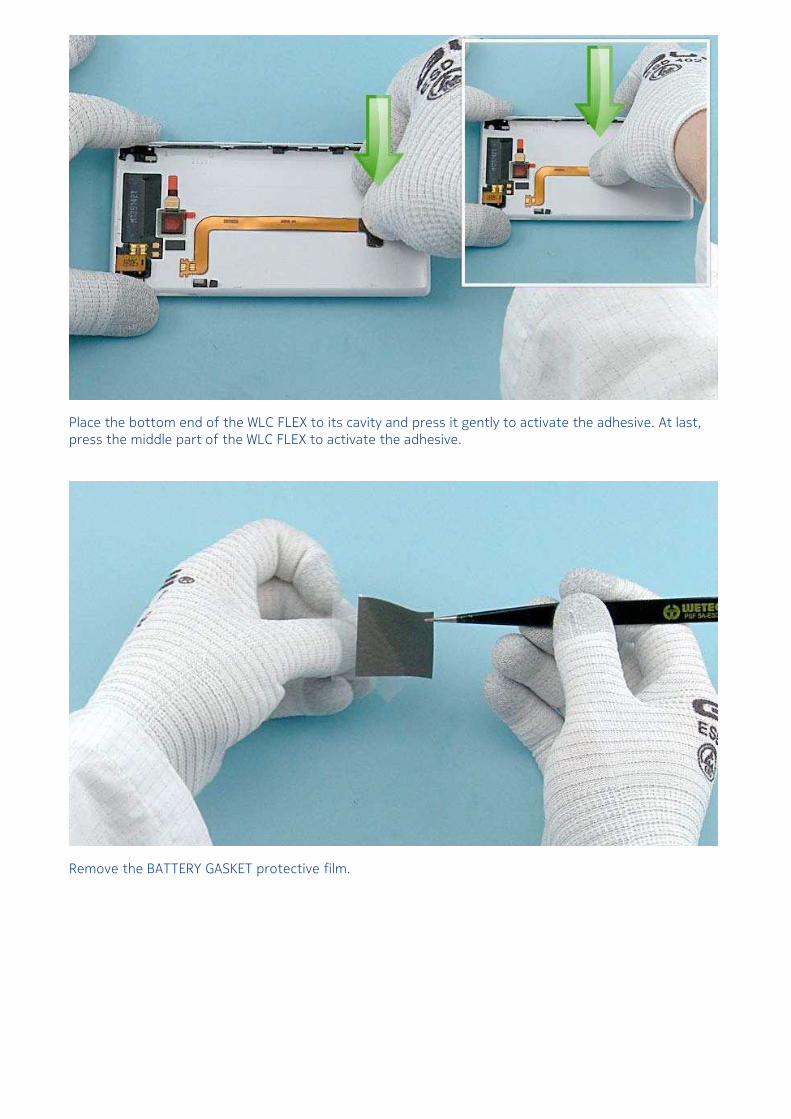
Place the bottom end of the WLC FLEX to its cavity and press it gently to activate the adhesive. At last,press the middle part of the WLC FLEX to activate the adhesive.
Remove the BATTERY GASKET protective film.
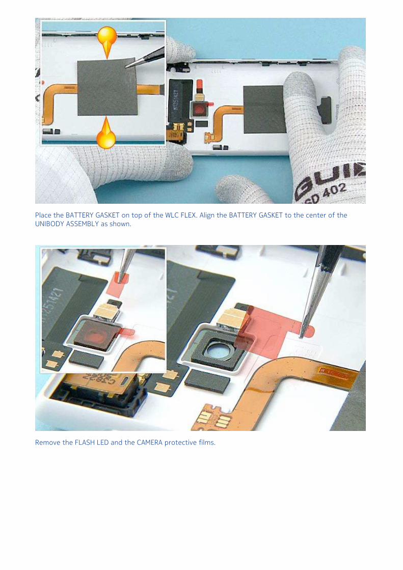
Place the BATTERY GASKET on top of the WLC FLEX. Align the BATTERY GASKET to the center of theUNIBODY ASSEMBLY as shown.
Remove the FLASH LED and the CAMERA protective films.
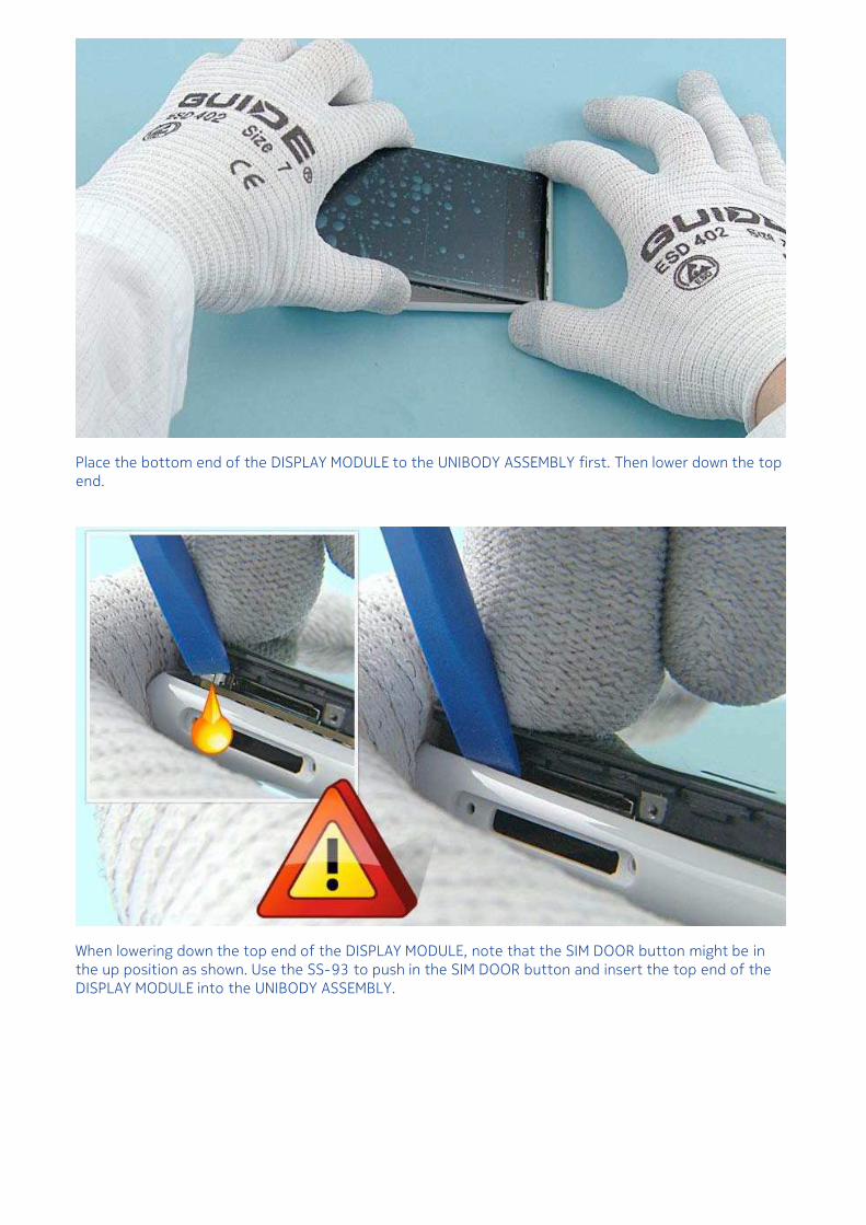
Place the bottom end of the DISPLAY MODULE to the UNIBODY ASSEMBLY first. Then lower down the topend.
When lowering down the top end of the DISPLAY MODULE, note that the SIM DOOR button might be inthe up position as shown. Use the SS-93 to push in the SIM DOOR button and insert the top end of theDISPLAY MODULE into the UNIBODY ASSEMBLY.
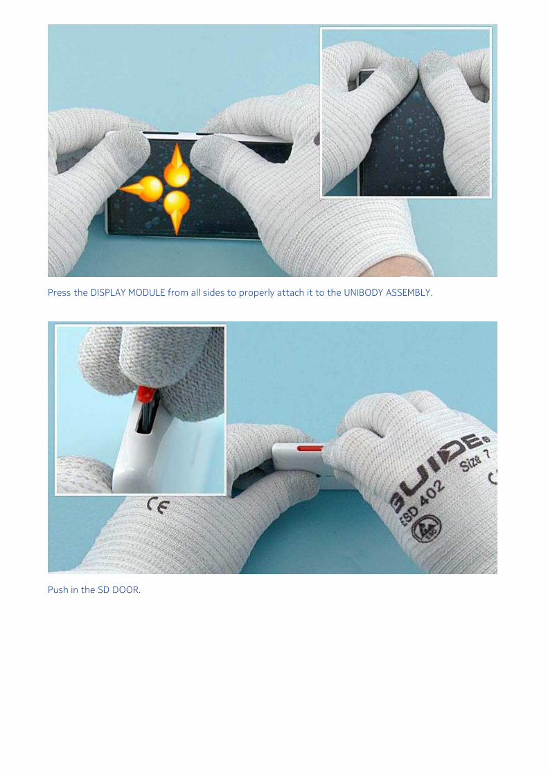
Press the DISPLAY MODULE from all sides to properly attach it to the UNIBODY ASSEMBLY.
Push in the SD DOOR.
Fasten the TORX+ size 2 screw to the torque of 7Ncm.
Push in the SIM DOOR.
Remove the DISPLAY protective film.
Remove the UNIBODY ASSEMBLY protective film.
The Nokia Lumia 720 assembly procedure is complete.