37
1 03890327-E K3VL Swash-plate type Axial piston pump Service Manual

103890327-E
K3VL
Swash-plate type Axial piston pump
Service Manual
2
Contents 1 Disassembly and Assembly of the Pump 3
1-1 Tools 3 1-2 Procedure of Disassembly 4 1-3 Procedure of Assembly 9 Attached Drawing No.1 Exploded Drawing 14 Attached Drawing No.2 K3VL45/A Cross Section 15 Attached Drawing No.3 K3VL80/A Cross Section 16 Attached Drawing No.4 K3VL112/A Cross Section 17 Attached Drawing No.5 K3VL140/A Cross Section 18
2 Disassembly and Assembly of Pressure Cut-off/Load Sensing Regulator 19 2-1 Tools 19 2-2 Procedure of Disassembly 20 2-3 Procedure of Assembly 22 Attached Drawing No.6 Exploded Drawing 24 Attached Drawing No.7 Cross Section KR3L-* * 25 Attached Drawing No.8 Cross Section KR3B-* * 26
3 Disassembly and Assembly of Torque Control Module 27
3-1 Tools 27 3-2 Procedure of Disassembly 28 3-3 Procedure of Assembly 31 Attached Drawing No.9 Exploded Drawing 34 Attached Drawing No.10 Cross Section KR3*-* * 35
4 Judging Standard for Maintenance 36
4-1 Judging Standard for replacing worn parts 36 4-2 Judging Standard of cylinder, valve plate, swash plate, and shoe plate 37
3
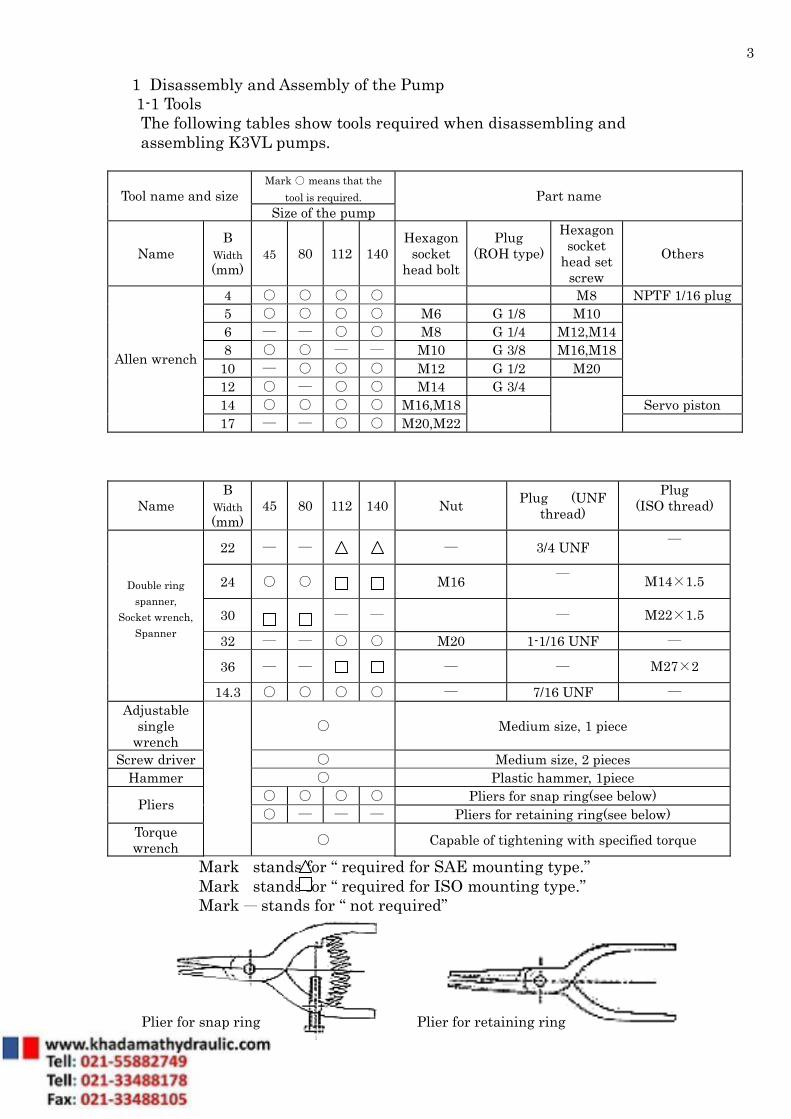
1 Disassembly and Assembly of the Pump 1-1 Tools The following tables show tools required when disassembling and assembling K3VL pumps.
Mark ○ means that the tool is required. Tool name and size
Size of the pump Part name
Name B
Width (mm)
45 80 112 140 Hexagon
socket head bolt
Plug (ROH type)
Hexagon socket
head set screw
Others
4 ○ ○ ○ ○ M8 NPTF 1/16 plug 5 ○ ○ ○ ○ M6 G 1/8 M10 6 ― ― ○ ○ M8 G 1/4 M12,M14 8 ○ ○ ― ― M10 G 3/8 M16,M18
10 ― ○ ○ ○ M12 G 1/2 M20 12 ○ ― ○ ○ M14 G 3/4
14 ○ ○ ○ ○ M16,M18 Servo piston
Allen wrench
17 ― ― ○ ○ M20,M22
Name B
Width (mm)
45 80 112 140 Nut Plug (UNF thread)
Plug (ISO thread)
22 ― ― ― 3/4 UNF ―
24 ○ ○ M16 ― M14×1.5
30 ― ― ― M22×1.5
32 ― ― ○ ○ M20 1-1/16 UNF ―
36 ― ― ― ― M27×2
Double ring spanner,
Socket wrench, Spanner
14.3 ○ ○ ○ ○ ― 7/16 UNF ― Adjustable
single wrench
○ Medium size, 1 piece
Screw driver ○ Medium size, 2 pieces Hammer ○ Plastic hammer, 1piece
○ ○ ○ ○ Pliers for snap ring(see below) Pliers ○ ― ― ― Pliers for retaining ring(see below)
Torque wrench
○ Capable of tightening with specified torque
Mark stands for “ required for SAE mounting type.” Mark stands for “ required for ISO mounting type.” Mark ― stands for “ not required” Plier for snap ring Plier for retaining ring

4
1-2 Procedure of Disassembly Before disassembling, read all pages of this disassembly section. When disassembling, follow the order of procedures written in the next table.
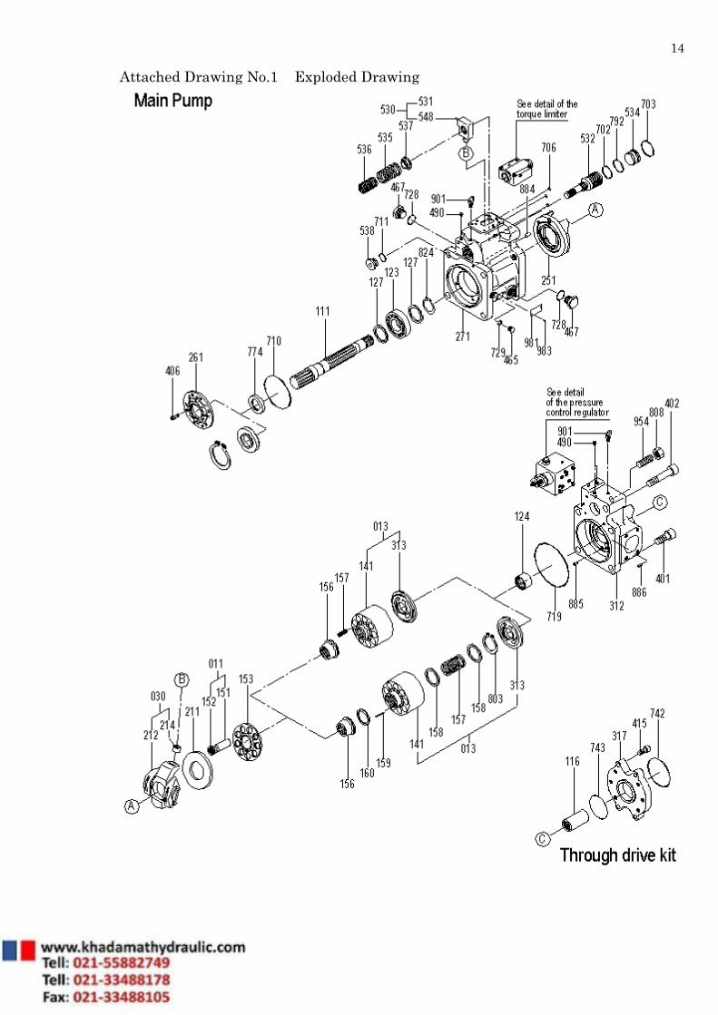
Numbers in the parentheses next to the part name shows the part number in the following drawings:
Attached Drawing No.1 Exploded Drawing Attached Drawing No.2 K3VL45/A Cross Section
Attached Drawing No.3 K3VL80/A Cross Section Attached Drawing No.4 K3VL112/A Cross Section Attached Drawing No.5 K3VL140/A Cross Section

5
№ Work Notes
1 Select an appropriate place to disassemble.
(1) The place must be clean. (2) Spread rubber sheet, cloth, etc. to
prevent parts from being damaged.
2 Remove dust, rust, and so on from the surface of the pump with cleaning oil.
3 Remove the drain plug (467) and drain off hydraulic oil out of pump casing (271).
(1) Drain off as much oil as possible.
4
Remove hexagon socket head bolts (411 in case of K3VL45, 80), (411 and 412 in case of K3VL112, 140), and then remove the regulator from the casing.
(1) When disassembling the regulator, refer to the manual of the regulator.
(2) Be careful not to drop O-ring from the gasket surface of the regulator.
(3) Prevent dust from entering into the regulator.
5
Loosen hexagon socket head bolt (401, 402) tightening valve cover(312) and the pump casing.
(1) Remove the regulator before loosening the bolts.
(2) In case through drive kit is installed, remove sub-plate adapter (317) and coupling (116) beforehand.
(3) Oil will come out from between pump casing (271) and valve cover (312). Be careful and remove oil to keep the place clean.
6
№ Work Notes
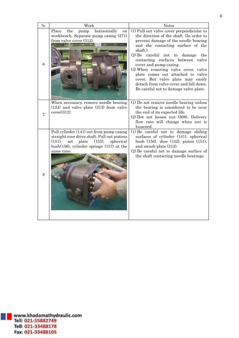
6
Place the pump horizontally on workbench. Separate pump casing (271) from valve cover (312).
(1) Pull out valve cover perpendicular to the direction of the shaft. (In order to prevent damage of the needle bearing and the contacting surface of the shaft.)
(2) Be careful not to damage the contacting surfaces between valve cover and pump casing.
(3) When removing valve cover, valve plate comes out attached to valve cover. But valve plate may easily detach from valve cover and fall down. Be careful not to damage valve plate.
7
When necessary, remove needle bearing (124) and valve plate (313) from valve cover(312).
(1) Do not remove needle bearing unless the bearing is considered to be near the end of its expected life.
(2) Dot not loosen nut (808). Delivery flow rate will change when nut is loosened.
8
Pull cylinder (141) out from pump casing straight over drive shaft. Pull out pistons (151), set plate (153), spherical bush(156), cylinder springs (157) at the same time.
(1) Be careful not to damage sliding surfaces of cylinder (141), spherical bush (156), shoe (152), piston (151), and swash-plate (212).
(2) Be careful not to damage surface of the shaft contacting needle bearings.

7
№ Work Notes
9
Remove retaining ring (406) in case of K3VL45 or hexagon socket head bolts (406) in case of K3VL80, 112, 140. Remove seal cover (261).
(1) In case of K3VL80, 112, 140, seal cover (261) is easily removed when two bolts are inserted into holes (with female thread).
(2) Be careful not to damage oil seal (774) on seal cover (261).
(3) In case of spline shaft, cover spline part with plastic tape so as not to damage oil seal. In case of key shaft, remove key before seal cover is removed.
10
Tapping drive shaft (111) lightly on the end of valve cover side with a plastic hammer, extract drive shaft from pump casing.
(1) Hold front side of shaft when tapping to prevent shaft from flying out.
(2) Tap shaft horizontally (in accordance with shaft direction) not to damage front roller bearing.
(3) As front roller bearing and shaft are fit tightly (shrinkage fit), do not remove front roller bearing unless it is considered to be near the end of its expected life.
11
Pushing down servo piston (532), remove shoe plate (211) and swash plate (212) from pump casing.
(1) Be careful not to damage shoe plate, and the sliding round surface of swash plate.
8
№ Work Notes
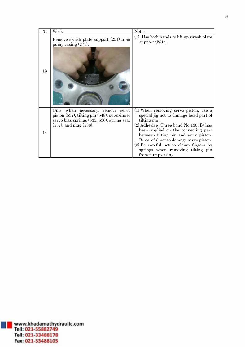
13
Remove swash plate support (251) from pump casing (271).
(1) Use both hands to lift up swash plate support (251) .
14
Only when necessary, remove servo piston (532), tilting pin (548), outer/inner servo bias springs (535, 536), spring seat (537), and plug (538).
(1) When removing servo piston, use a special jig not to damage head part of tilting pin.
(2) Adhesive (Three bond No.1305B) has been applied on the connecting part between tilting pin and servo piston. Be careful not to damage servo piston.
(3) Be careful not to clamp fingers by springs when removing tilting pin from pump casing.

9
1-3 Procedure of Assembly When assembling, the order of procedures is the reverse of disassembly. Be careful of next items.
(1) Before assembling, make sure that all parts are prepared and all damaged parts are fixed or replaced by new ones.
(2) Before assembling, wash each part with clean oil and dry it with compressed air. Select an appropriate clean place to assemble. When dust enters, it may cause trouble.
(3) When assembling, apply clean working fluid on the sliding surfaces and bearings. (4) Do not reuse O-ring, oil seal, and other seal parts. Replace with new one. (5) When assembling parts that easily detach, like an O-ring, apply clean grease to
prevent them from dropping downward. (6) Tighten fitting bolts and plugs using a torque wrench with standard torques
shown on the drawing of each size.
10
№ Work Notes
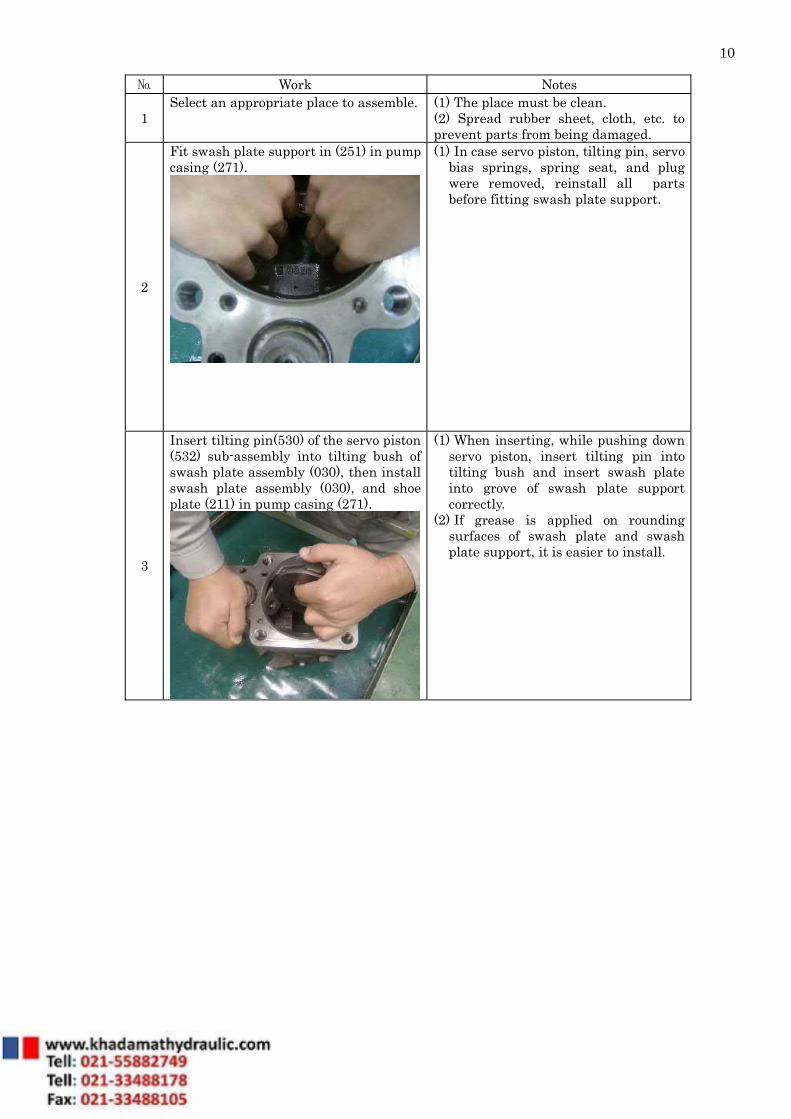
1 Select an appropriate place to assemble.
(1) The place must be clean. (2) Spread rubber sheet, cloth, etc. to prevent parts from being damaged.
2
Fit swash plate support in (251) in pump casing (271).
(1) In case servo piston, tilting pin, servo bias springs, spring seat, and plug were removed, reinstall all parts before fitting swash plate support.
3
Insert tilting pin(530) of the servo piston (532) sub-assembly into tilting bush of swash plate assembly (030), then install swash plate assembly (030), and shoe plate (211) in pump casing (271).
(1) When inserting, while pushing down servo piston, insert tilting pin into tilting bush and insert swash plate into grove of swash plate support correctly.
(2) If grease is applied on rounding surfaces of swash plate and swash plate support, it is easier to install.
11
№. Work Notes
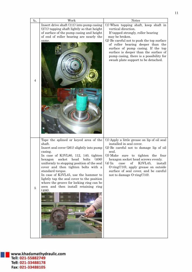
4
Insert drive shaft (111) into pump casing (271) tapping shaft lightly so that height of surface of the pump casing and height of end of roller bearing are nearly the same.
(1) When tapping shaft, keep shaft in vertical direction.
If tapped strongly, roller bearing may be broken. (2) Be careful not to push the top surface
of roller bearing deeper than the surface of pump casing. If the top surface is deeper than the surface of pump casing, there is a possibility for swash plate support to be detached.
5
Tape the splined or keyed area of the shaft. Insert seal cover (261) slightly into pump casing. In case of K3VL80, 112, 140, tighten hexagon socket head bolts (406) uniformly to stopping position of the seal cover and then tighten bolts with a standard torque. In case of K3VL45, use the hammer to lightly tap the seal cover to the position where the groove for locking ring can be seen and then install retaining ring (406).
(1) Apply a little grease on lip of oil seal installed in seal cover.
(2) Be careful not to damage lip of oil seal.
(3) Make sure to tighten the four hexagon socket head screws evenly.
(4) In case of K3VL45, install O-ring(710), apply grease on outside surface of seal cover, and be careful not to damage O-ring(710).

12
№ Work Notes
6
Assemble cylinder (141), piston-sub (011), spherical bush (156), set plate (153), and cylinder spring (157) into a sub assembly.
(1)Incase of K3VL45/A Install cylinder spring, ring guide, and retaining ring into cylinder and then assemble pin, spacer, spherical bush, set plate, piston-sub to set a sub- assembly.
(2) Be careful not to damage sliding surfaces between piston and cylinder bore, and between cylinder and valve plate.
7
Place pump casing (271) horizontally with surface of regulator downward. Install piston-cylinder sub into pump casing.
(1) Be careful not to drop parts for piston-cylinder sub such as cylinder spring and roller.
(2) Be careful not to damage bearing-contacting surface of the shaft when installing a piston- cylinder sub.
8
Install valve plate (313) on valve cover (312).
(1) In case that stopper (534), max flow set screw (954), and max flow set screw lock nut (808) have been removed, install these parts on valve cover (312) beforehand.
(2) Do not mistake suction/delivery direction of valve plate (313). When installing valve plate, make sure that pin (885) enters into the slit of valve plate (313).
(3) If grease is applied on contacting surfaces of valve plate (313) and valve cover (312), it is easier to install valve cover (312).

13
№ Work Notes
9
Install valve cover (312) on pump casing (271). Tighten hexagon socket head bolts (411 in case of K3VL45, 80), (411 and 412 in case of K3VL112, 140),
(1) In assembling valve cover, be careful not to damage shaft and contacting surface of needle bearing.
10
Install regulators on the valve cover (312) or pump casing (271) . When installing torque limit regulator , make sure that feed back lever (611) of regulator is engaged with feed back pin .
(1) Make sure that O ring on the gasket surface of regulator does not drop out.
14
Attached Drawing No.1 Exploded Drawing
15
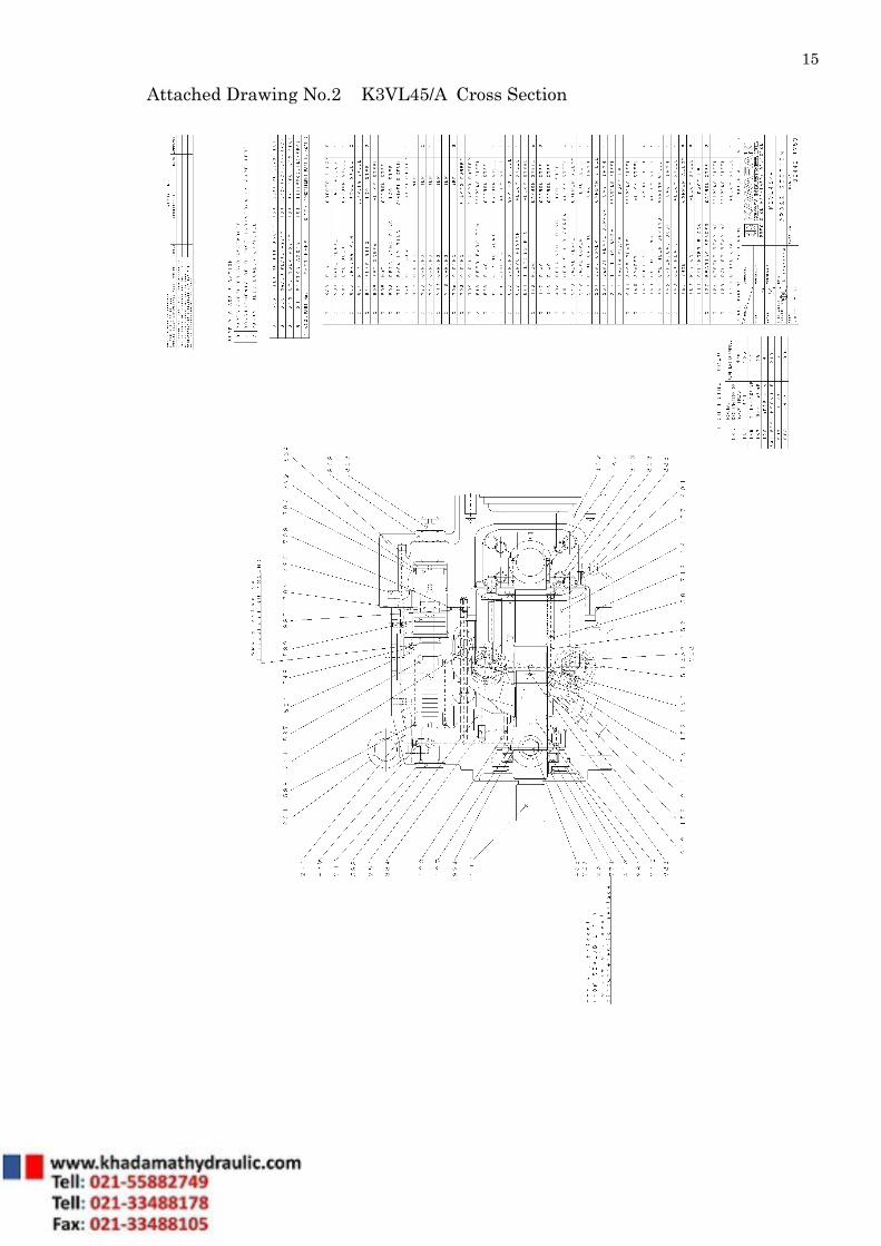
Attached Drawing No.2 K3VL45/A Cross Section
16
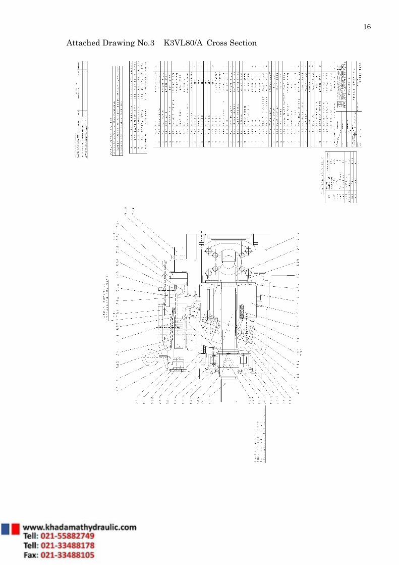
Attached Drawing No.3 K3VL80/A Cross Section
17
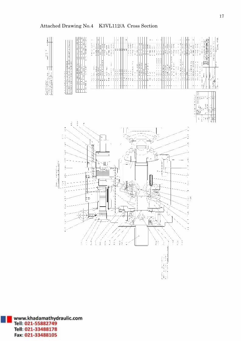
Attached Drawing No.4 K3VL112/A Cross Section
18
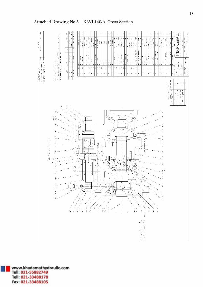
Attached Drawing No.5 K3VL140/A Cross Section
19
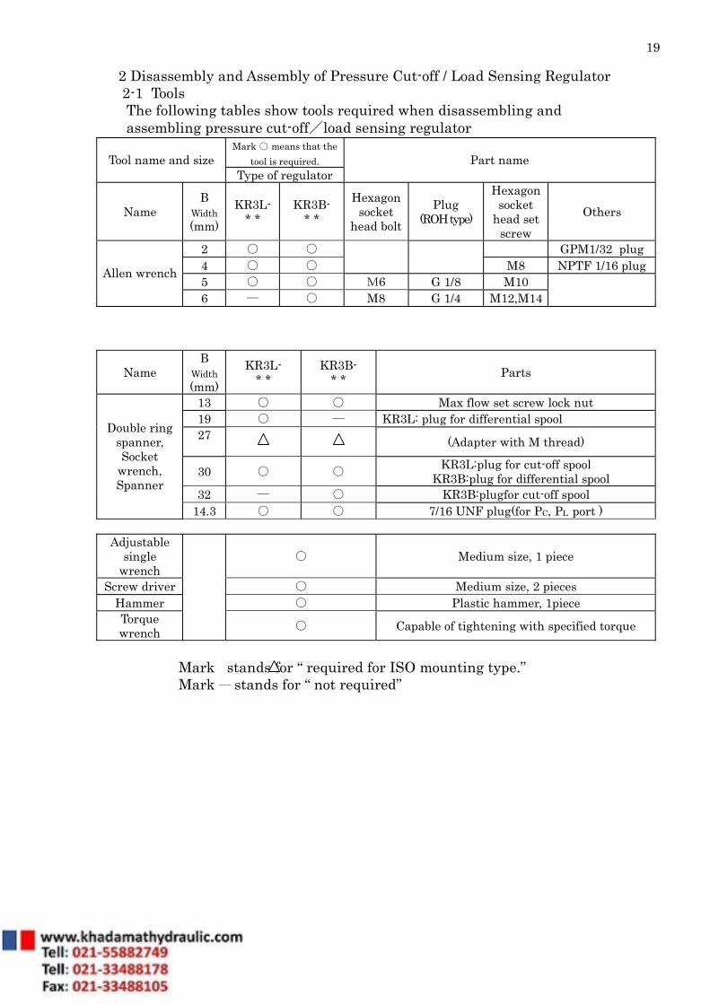
2 Disassembly and Assembly of Pressure Cut-off / Load Sensing Regulator 2-1 Tools The following tables show tools required when disassembling and assembling pressure cut-off/load sensing regulator
Mark ○ means that the tool is required. Tool name and size
Type of regulator Part name
Name B
Width (mm)
KR3L- * *
KR3B- * *
Hexagonsocket
head bolt Plug
(ROH type)
Hexagon socket
head set screw
Others
2 ○ ○ GPM1/32 plug 4 ○ ○
M8 NPTF 1/16 plug 5 ○ ○ M6 G 1/8 M10
Allen wrench
6 ― ○ M8 G 1/4 M12,M14
Name B
Width (mm)
KR3L- * *
KR3B- * * Parts
13 ○ ○ Max flow set screw lock nut 19 ○ ― KR3L: plug for differential spool 27 (Adapter with M thread)
30 ○ ○ KR3L:plug for cut-off spool KR3B:plug for differential spool
32 ― ○ KR3B:plugfor cut-off spool
Double ring spanner, Socket
wrench, Spanner
14.3 ○ ○ 7/16 UNF plug(for PC, PL port )
Adjustable single
wrench ○ Medium size, 1 piece
Screw driver ○ Medium size, 2 pieces Hammer ○ Plastic hammer, 1piece Torque wrench
○ Capable of tightening with specified torque
Mark stands for “ required for ISO mounting type.” Mark ― stands for “ not required”

20
2-2 Procedure of Disassembly Before disassembling, read all pages of this manual. When disassembling, follow the order of procedures written in the next table.
Numbers in the parentheses next to the part name shows the part number in the following drawings: Attached Drawing No.6 Exploded Drawing Attached Drawing No.7 Cross Section KR3L - * * Attached Drawing No.8 Cross Section KR3B - * *
21
№ Work Notes
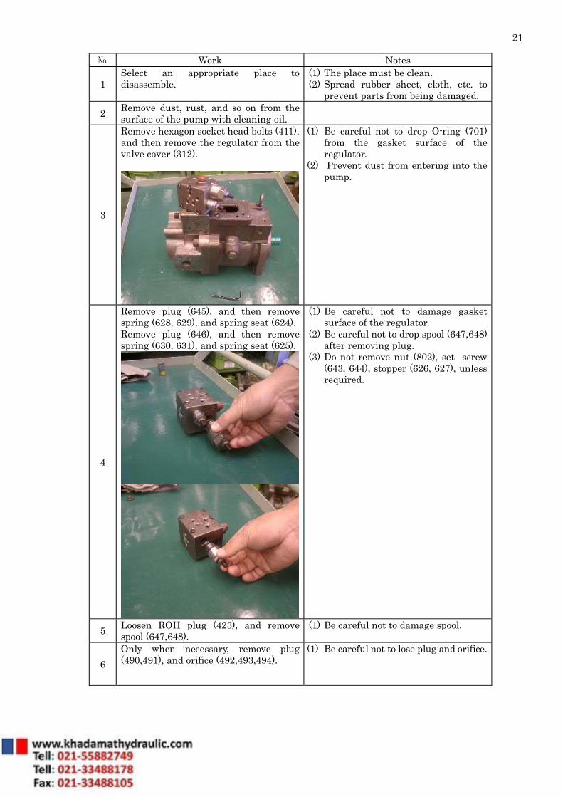
1 Select an appropriate place to disassemble.
(1) The place must be clean. (2) Spread rubber sheet, cloth, etc. to
prevent parts from being damaged.
2 Remove dust, rust, and so on from the surface of the pump with cleaning oil.
3
Remove hexagon socket head bolts (411), and then remove the regulator from the valve cover (312).
(1) Be careful not to drop O-ring (701) from the gasket surface of the regulator.
(2) Prevent dust from entering into the pump.
4
Remove plug (645), and then remove spring (628, 629), and spring seat (624). Remove plug (646), and then remove spring (630, 631), and spring seat (625).
(1) Be careful not to damage gasket surface of the regulator.
(2) Be careful not to drop spool (647,648) after removing plug.
(3) Do not remove nut (802), set screw (643, 644), stopper (626, 627), unless required.
5 Loosen ROH plug (423), and remove spool (647,648).
(1) Be careful not to damage spool.
6 Only when necessary, remove plug (490,491), and orifice (492,493,494).
(1) Be careful not to lose plug and orifice.

22
2-3 Procedure of Assembly When assembling, the order of procedures is the reverse of disassembly. Be careful of next items.
(1) Before assembling, make sure that all parts are prepared and all damaged parts are fixed or replaced by new ones.
(2) Before assembling, wash each part with clean oil and dry it with compressed air. Select an appropriate clean place to assemble. When dust enters, it may cause trouble.
(3) When assembling, apply clean working fluid on the sliding surfaces and. (4) Do not reuse O-ring, oil seal, and other seal parts. Replace with new one. (5) When assembling parts that easily detach, like an O-ring, apply clean grease to
prevent them from dropping downward. (6) Tighten fitting bolts and plugs using a torque wrench with standard torques
shown on the drawing of each size.
23
№ Work Notes
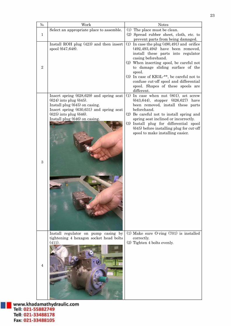
1 Select an appropriate place to assemble.
(1) The place must be clean. (2) Spread rubber sheet, cloth, etc. to
prevent parts from being damaged.
2
Install ROH plug (423) and then insert spool (647,648).
(1) In case the plug (490,491) and orifice (492,493,494) have been removed, install these parts into regulator casing beforehand.
(2) When inserting spool, be careful not to damage sliding surface of the spool.
(3) In case of KR3L-**, be careful not to confuse cut-off spool and differential spool. Shapes of these spools are different.
3
Insert spring (628,629) and spring seat (624) into plug (645). Install plug (645) on casing. Insert spring (630,631) and spring seat (625) into plug (646). Install plug (646) on casing.
(1) In case when nut (801), set screw (643,644), stopper (626,627) have been removed, install these parts beforehand.
(2) Be careful not to install spring and spring seat inclined or incorrectly.
(3) Install plug for differential spool (645) before installing plug for cut-off spool to make installing easier.
4
Install regulator on pump casing by tightening 4 hexagon socket head bolts (411).
(1) Make sure O-ring (701) is installed correctly.
(2) Tighten 4 bolts evenly.

24
Attached Drawing No.6 Exploded Drawing

25
Attached Drawing No.7 Cross Section KR3L - * *

26
Attached Drawing No.8 Cross Section KR3B - * *
27
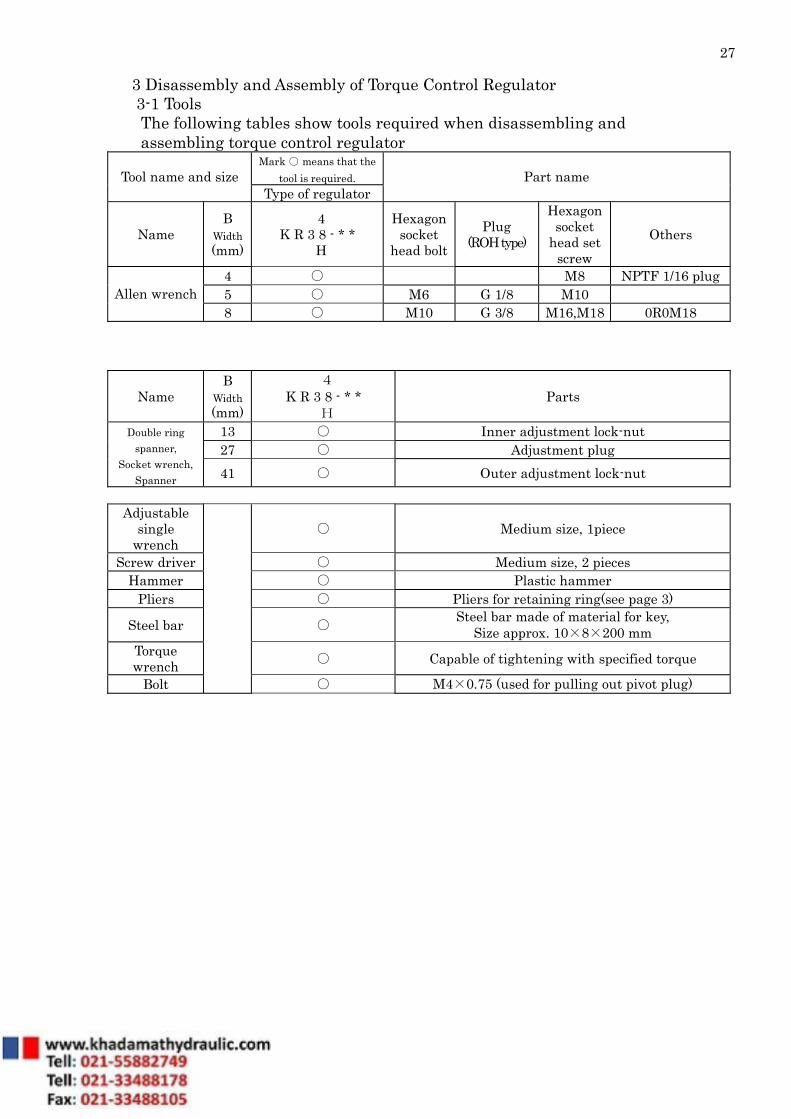
3 Disassembly and Assembly of Torque Control Regulator 3-1 Tools The following tables show tools required when disassembling and assembling torque control regulator
Mark ○ means that the tool is required. Tool name and size
Type of regulator Part name
Name B
Width (mm)
4 K R 3 8 - * *
H
Hexagon socket
head bolt Plug
(ROH type)
Hexagon socket
head set screw
Others
4 ○ M8 NPTF 1/16 plug 5 ○ M6 G 1/8 M10 Allen wrench 8 ○ M10 G 3/8 M16,M18 0R0M18
Name B
Width (mm)
4 K R 3 8 - * *
H Parts
13 ○ Inner adjustment lock-nut 27 ○ Adjustment plug
Double ring spanner,
Socket wrench, Spanner 41 ○ Outer adjustment lock-nut
Adjustable
single wrench
○ Medium size, 1piece
Screw driver ○ Medium size, 2 pieces Hammer ○ Plastic hammer
Pliers ○ Pliers for retaining ring(see page 3)
Steel bar ○ Steel bar made of material for key, Size approx. 10×8×200 mm
Torque wrench ○ Capable of tightening with specified torque
Bolt
○ M4×0.75 (used for pulling out pivot plug)

28
3-2 Procedure of Disassembly Before disassembling, read all pages of this manual. When disassembling, follow the order of procedures written in the next table.
Numbers in the parentheses next to the part name shows the part number in the following drawings: Attached Drawing No.9 Exploded Drawing Attached Drawing No.10 Cross Section KR3* - * *

29
№ Work Notes
1 Select an appropriate place to disassemble.
(1) The place must be clean. (2) Spread rubber sheet, cloth, etc. to
prevent parts from being damaged.
2 Remove dust, rust, and so on from the surface of the pump with cleaning oil.
3
Remove hexagon socket head bolts (412), and then remove the regulator from the casing.
(1) Be careful not to drop O-rings (701,705) from the gasket surface of the regulator.
(2) Prevent dust from entering into the regulator.
4
Loosen lock nut (630). Remove adjusting plug (628), spring (625,626), spring seat (624).
(1) Be careful not to damage gasket surface of the regulator.
(2) Be careful not to drop spool (621), when and after removing adjusting plug.
(3) Do not remove nut (801), set screw (924), adjustment stem (627), unless required.
30
No. Work Notes
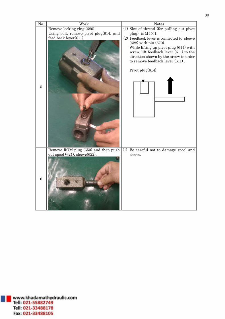
5
Remove locking ring (680). Using bolt, remove pivot plug(614) and feed back lever(611).
(1) Size of thread (for pulling out pivot plug) is M4×1.
(2) Feedback lever is connected to sleeve (622) with pin (670). While lifting up pivot plug (614) with screw, lift feedback lever (611) to the direction shown by the arrow in order to remove feedback lever (611) . Pivot plug(614)
6
Remove ROM plug (650) and then push out spool (621), sleeve(622).
(1) Be careful not to damage spool and sleeve.

31
3-3 Procedure of Assembly When assembling, the order of procedures is the reverse of disassembly. Be careful of next items.
(1) Before assembling, make sure that all parts are prepared and all damaged parts are fixed or replaced by new ones.
(2) Before assembling, wash each part with clean oil and dry it with compressed air. Select an appropriate clean place to assemble. When dust enters, it may cause trouble. (3) When assembling, apply clean working fluid on the sliding surfaces. (4) Do not reuse O-ring, oil seal, and other seal parts. Replace with new one. (5) When assembling parts that easily detach, like an O-ring, apply clean grease to
prevent them from dropping downward. (6) Tighten fitting bolts and plugs using a torque wrench with standard torques
shown on the drawing of each size.

32
№ Work Notes
1 Select an appropriate place to assemble.
(1) The place must be clean. (2) Spread rubber sheet, cloth, etc. to
prevent parts from being damaged.
2
Adjust the position of the hole for feed back pin on sleeve to be seen from outside the hole for pivot plug on regulator casing, insert sleeve (622) and spool (621).
(1) In case that plug (660) have been removed, install plug into regulator casing beforehand.
(2) Be careful not to damage sliding surfaces when assembling sleeve and spool.
3
Install feedback lever so that pin (670) of feedback lever (611) enters into a hole of sleeve.
(1) Adjust the position of the feedback
lever (611) so that the pivot pin hole on the feed back lever can be seen from the pivot plug hole on casing.
33
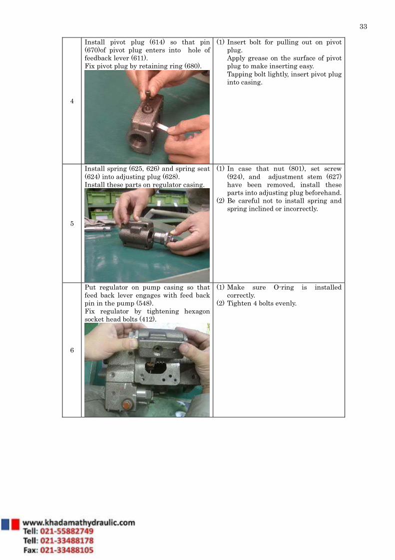
4
Install pivot plug (614) so that pin (670)of pivot plug enters into hole of feedback lever (611). Fix pivot plug by retaining ring (680).
(1) Insert bolt for pulling out on pivot plug. Apply grease on the surface of pivot plug to make inserting easy. Tapping bolt lightly, insert pivot plug into casing.
5
Install spring (625, 626) and spring seat (624) into adjusting plug (628). Install these parts on regulator casing.
(1) In case that nut (801), set screw (924), and adjustment stem (627) have been removed, install these parts into adjusting plug beforehand.
(2) Be careful not to install spring and spring inclined or incorrectly.
6
Put regulator on pump casing so that feed back lever engages with feed back pin in the pump (548). Fix regulator by tightening hexagon socket head bolts (412).
(1) Make sure O-ring is installed correctly.
(2) Tighten 4 bolts evenly.
34
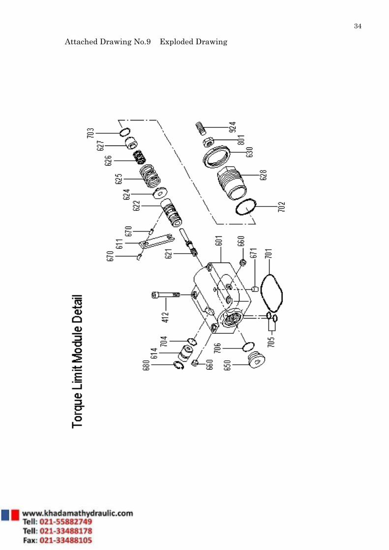
Attached Drawing No.9 Exploded Drawing

35
Attached Drawing No.10 Cross Section KR3* - * *
36
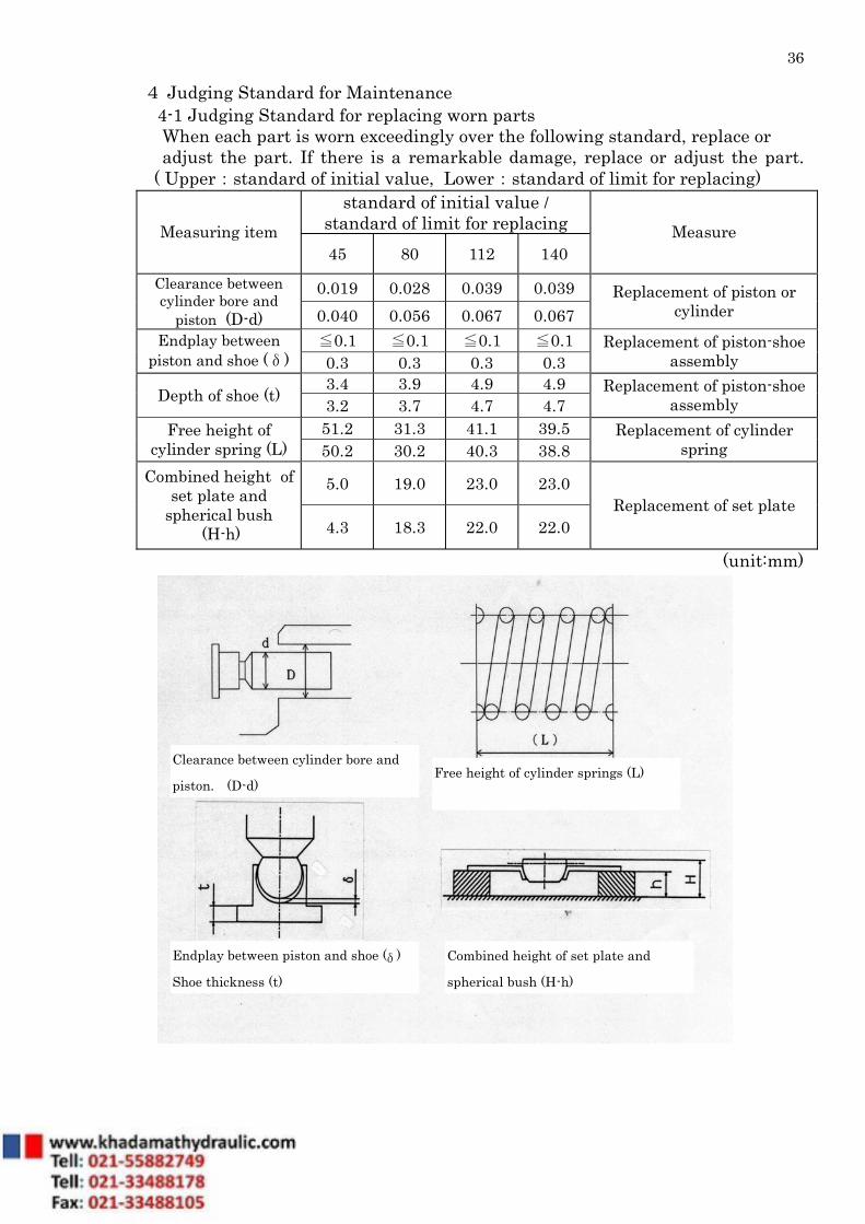
4 Judging Standard for Maintenance 4-1 Judging Standard for replacing worn parts When each part is worn exceedingly over the following standard, replace or adjust the part. If there is a remarkable damage, replace or adjust the part.
( Upper:standard of initial value, Lower:standard of limit for replacing) standard of initial value /
standard of limit for replacing Measuring item 45 80 112 140
Measure
0.019 0.028 0.039 0.039 Clearance between cylinder bore and
piston (D-d) 0.040 0.056 0.067 0.067 Replacement of piston or
cylinder
≦0.1 ≦0.1 ≦0.1 ≦0.1 Endplay between piston and shoe (δ) 0.3 0.3 0.3 0.3
Replacement of piston-shoe assembly
3.4 3.9 4.9 4.9 Depth of shoe (t) 3.2 3.7 4.7 4.7 Replacement of piston-shoe
assembly 51.2 31.3 41.1 39.5 Free height of
cylinder spring (L) 50.2 30.2 40.3 38.8 Replacement of cylinder
spring
5.0 19.0 23.0 23.0 Combined height of set plate and
spherical bush (H-h) 4.3 18.3 22.0 22.0
Replacement of set plate
(unit:mm)
Clearance between cylinder bore and piston. (D-d)
Endplay between piston and shoe ( δ ) Shoe thickness (t)
Combined height of set plate and spherical bush (H-h)
Free height of cylinder springs (L)
37
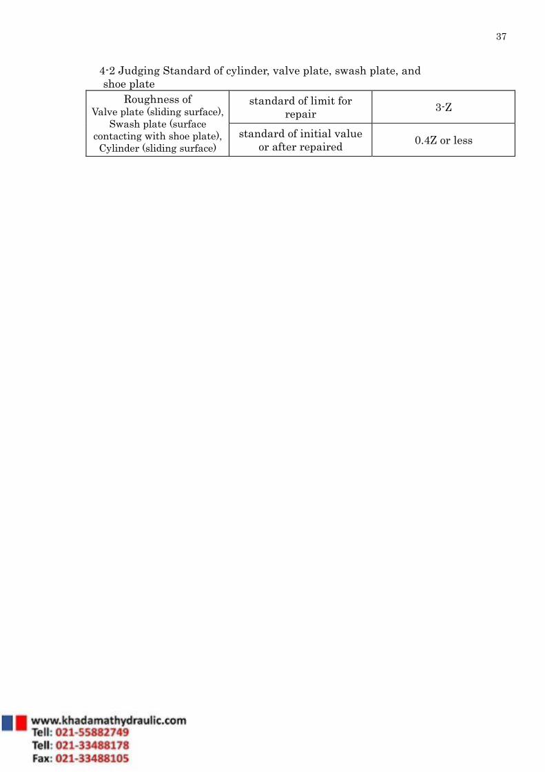
4-2 Judging Standard of cylinder, valve plate, swash plate, and
shoe plate standard of limit for
repair 3-Z Roughness of
Valve plate (sliding surface), Swash plate (surface
contacting with shoe plate), Cylinder (sliding surface)
standard of initial value or after repaired 0.4Z or less


