53
SERVICE MANUAL To Suit Model: REU-VRM2632WC

SERVICE MANUAL
To Suit Model:REU-VRM2632WC

All Rinnai products are certified by the Australian Gas Association as compliantto relevant Australian Standards.
Rinnai Australia Head Office is certifiedas complying with ISO 9001 by SAIGlobal.
Rinnai New Zealand has been certified toISO 9001 Quality Assurance by Telarc.
All Rinnai products are Certified toWaterMark by SAI Global. WaterMarkcertification is awarded to products andfittings complying with safety and watercontamination standards.
Distributed and serviced in Australia under a Quality System certified as complying with ISO 9001 by SAI Global
SAI Global

© Copyright Rinnai Australia Pty Ltd ABN 74 005 138 769 All rights reservedProduced by Engineering & Technical Group
No portion or part of this manual may be copied without prior permission from Rinnai Australia.
Rinnai Australia reserves the right to make modifications and change specifications without notice.
Failure to comply with these instructions may result in serious personal injury or damage to the appliance.
This manual has been published by Rinnai Australia Engineering & Technical Group.
We welcome users of this manual to provide feedback and suggestions for improvement purposes.
W A R N I N G
• All wiring inside this appliance my be at 240 Volts potential.• All service work must be carried out by an authorised person.
WARNING
WARNING

REU-VRM2632WC (HD200e) - 1 - Issue 1 - 16/12/09 ©Rinnai
Table of Contents
Glossary of Terms and Symbols ........................................... ...................................... 2
1. Specifications ............................................................................................................. 3
2. Water Flow Rates and Pressure Characteristics ........................................................ 5
3. Dimensions ................................................................................................................ 6
4. Water Controllers ....................................................................................................... 7
5. Cutaway Diagram ...................................................................................................... 9
6. Smartstart ................................................................................................................. 10
7. Operational Flow Chart ........................................................................................... 12
8. Operation Principles ................................................................................................ 13
9. Main Components .................................................................................................... 15
10. Time Charts ............................................................................................................ 16
11. Wiring Diagram ..................................................................................................... 17
12. Dip Switch Settings ............................................................................................... 18
13. Diagnostic Points ................................................................................................... 20
14. Fault Finding .......................................................................................................... 21
15. Component and Circuit Checks ............................................................................. 23
16. Maintenance Monitor / Error History .................................................................... 30
17. Gas Pressure Setting Procedure ............................................................................. 33
18. Gas Conversion Procedure ..................................................................................... 33
19. Dismantling for Service ......................................................................................... 35
20. Parts List ................................................................................................................ 4 4
21. Exploded Diagrams ................................................................................................ 47

REU-VRM2632WC (HD200e) - 2 - Issue 1 - 16/12/09 ©Rinnai
Glossary of Terms and Symbols
dB(A) - sound pressure level in decibels, “A” range
DC - direct current
AC - alternating current
WFCD - water flow control device
FB - feedback information
FF - feedforward information
Hz - Hertz
IC - integrated circuit
kcal/h - kilocalorie per hour
kPa - kilopascals
LED - light emitting diode
L/min - Litres per minute
mA - milliamps
MJ/h - megajoule per hour
mm - millimetres
mmH2O - millimetres of water (gauge pressure)
OHS - overheat switch
PCB - printed circuit board
CPU - central processing unit
POT - potentiometer
rpm - revolutions per minute
SV - solenoid valve
ø - diameteroC - temperature rise above ambient
POV - modulating valve
TE - thermal efficiency
TH - thermistor
TIN - temperature of incoming water
TOUT - temperature of outgoing water
REU-VRM2632WC (HD200e) - 3 - Issue 1 - 16/12/09 ©Rinnai
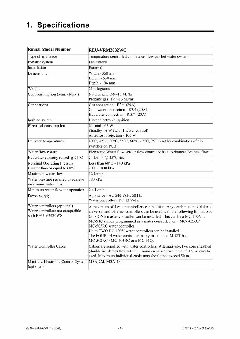
1. Specifications
Rinnai Model Number REU-VRM2632WC Type of appliance Temperature controlled continuous flow gas hot water systemExhaust system Fan ForcedInstallation External Dimensions Width - 350 mm
Height - 530 mmDepth - 194 mm
Weight 21 kilogramsGas consumption (Min. / Max.) Natural gas: 199~16 MJ/hr
Propane gas: 199~16 MJ/hrConnections Gas connection - R3/4 (20A)
Cold water connection - R3/4 (20A)Hot water connection - R 3/4 (20A)
Ignition system Direct electronic ignitionElectrical consumption Normal - 65 W
Standby - 6 W (with 1 water control)Anti-frost protection - 100 W
Delivery temperatures 40°C, 42°C, 50°C, 55°C, 60°C, 65°C, 75°C (set by combination of dip switches on PCB)
Water flow control Electronic Water flow sensor flow control & heat exchanger By-Pass flow. Hot water capacity raised @ 25°C 24 L/min @ 25°C riseNominal Operating PressureGreater than or equal to 60°C
Less than 60°C - 140 kPa200 ~ 1000 kPa
Maximum water flow 32 L/min.Water pressure required to achieve maximum water flow
180 kPa
Minimum water flow for operation 2.4 L/min.Power supply Appliance - AC 240 Volts 50 Hz
Water controller - DC 12 Volts Water controllers (optional)Water controllers not compatible with REU-V2426WS
A maximum of 4 water controllers can be fitted. Any combination of deluxe, universal and wireless controllers can be used with the following limitations:Only ONE master controller can be installed. This can be a MC-100V, a MC-91Q (when programmed as a mater controller) or a MC-502RC/MC-503RC water controller.Up to TWO BC-100V water controllers can be installed.The FOURTH water controller in any installation MUST be a MC-502RC / MC-503RC or a MC-91Q.
Water Controller Cable Cables are supplied with water controllers. Alternatively, two core sheathed (double insulated) flex with minimum cross sectional area of 0.5 m² may be used. Maximum individual cable runs should not exceed 50 m.
Manifold Electronic Control System (optional)
MSA-2M, MSA-2S

REU-VRM2632WC (HD200e) - 4 - Issue 1 - 16/12/09 ©Rinnai
Sensors and Safety Functions• Hot Water Delivery Thermistor: Measures hot water temperature at the outlet valve (i.e. the ‘mixed’
temperature).• Flame Rod: Monitors combustion characterist ics inside the combustion chamber . If the flame fails,
gas supply is stopped.• Overheat Switch: Situate d on the hea t exchanger, gas supply is stop ped wh en wate r temperature
reaches 97ºC for a number of seconds.• Fusible Link: Situated on the heat excha nger, electrical power supply is stopped if the temperature
exceeds 129ºC.• Water Pressure Relief Valve: Safeguards the water circuit against excessive inlet pressure. Opens at
2060 kPa, closes at 1470 kPa.• Electrical Fuse: (3A glass fuse) prevents against power surges. • Surge Protector: prevents against over-current.• Boil Dry Prevention: If water flow sensor detects no flow, gas supply is stopped.• Combustion Fan Speed Sensor: In case of combustion fan defect (no rotation of fan blades) gas sup-
ply is stopped.• Temperature Cutout: If the delivered hot water temperature rises above the required delivery
temperature for a number of seconds, the gas supply is stopped.
Combustion SpecificationsRefer to dataplate on appliance.
REU-VRM2632WC (HD200e) - 5 - Issue 1 - 16/12/09 ©Rinnai
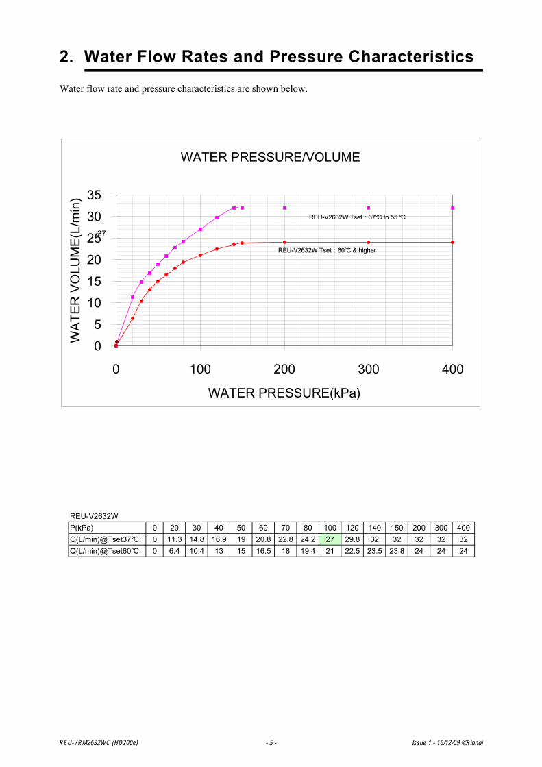
2. Water Flow Rates and Pressure Characteristics
Water flow rate and pressure characteristics are shown below.

REU-VRM2632WC (HD200e) - 6 - Issue 1 - 16/12/09 ©Rinnai
3. Dimensions
Dim' Description
RE
U-V
RM
2632
WC
A Width 350B Depth 194C Height - Unit 530D Height - Including Brackets 571E Hot Water outlet (from wall) 87F Hot Water outlet (from centre) 105G Cold Water inlet (from wall) 68H Cold Water inlet (from centre) 10I Gas Connection (from wall) 77J Gas Connection (from centre) 83
Gas: Length (from base) 40Cold: Length (from base) 50Hot: Length (from base) 42Gas: Fitting Diameter 20Cold: Fitting Diameter 20Hot: Fitting Diameter 20
K
L
BC-100V
MC-100V
MC-91Q
90
12
0
83
12
01
04
128
2022
02
02
2
181
B
DC
K
A
E
F J
H
IG
L FITTING
DIAMETER
* Please note that this measurement is to the left of the centre line.
83

4. Water Controllers
All water controllers must be installed in accordance with the relevant operation/installation instructions supplied with the water heater or controllers.
Trouble shooting
Water Controller not showing display - (Wired Water Controllers)
• Check that the correct number and combination of controllers have been installed for the specificmodel Infinity. Refer to controller compatibility table below.
• Check controller is turned ON.
• Check there is 12VDC power supply available to the controller from the Ezi-connect terminals.
• If there is 12VDC available from the Ezi Connect but no controller display, check wiring betweenEzi-connect and controller is sound.
• If there is no power from the Ezi-connect terminals, but the hot water functions correctly, replacePCB.
Error Code 12 as soon as hot water tap is turned ON.
• Check 12VDC internal wiring to Ezi-connect terminal is not crushed, or shortened.
• Rectify wiring and re-close Ezi-connect cover carefully.
Water Controller not showing display - (Wireless Water Controllers)
• Ensure transceiver module is mounted in the correct location, as per wireless controller installationinstructions.
• Ensure 2 x AA batteries are in good working order and installed with the correct polarity within thewireless controller. (Battery polarity details on rear of wireless controller)
• Ensure distance between wireless controller and transceiver does not exceed 50 metres.
• Ensure channel has been allocated to each wireless controller.
• Ensure wireless controller has been programmed to the transceiver correctly, as per wirelesscontroller installation instructions.
Water Controller Compatibility Table
Care should be taken to ensure power supply to the Infinity is isolated whenconnecting / disconnecting controller wiring or transponder on wireless controllers.Failure to isolate power supply may result in damage to the appliance PCB.
Care should be taken when closing the Ezi-connect access panel, to ensure internalwiring for controllers is not shortened or crushed.
Wireless Only Installation
A maximum of 4 wireless water controllers can be fitted with the following limitation:Only ONE MC-502RC or MC-503RC can be set as the Master Controller.
Wired & Wireless
Installations
A maximum of 4 water controllers can be fitted. Any combination of deluxe, universal andwireless controllers can be used with the following limitation:
Only ONE master controller can be installed. This can be a MC-100V, a MC-91Q (whenprogrammed as a master controller) or a MC-502RC or MC-503RC water controller.
Up to TWO BC-100V water controllers can be installed.
The FOURTH water controllers in any installation MUST BE a MC-502RC/MC-503RCor a MC91Q.
NOTE
REU-VRM2632WC (HD200e) - 7 - Issue 1 - 16/12/09 ©Rinnai

PROGRAMMING FOR THE ‘UNIVERSAL’ WATER CONTROLLER (MC-91Q)
Are there four water controllers connected?
IF NO: (You have three water controllers or fewer), go to Question 2.
IF YES: You will need to activate the fourth water controller as follows:
STEP 1: For the water controller in the KITCHEN ONLY, press and holdthe ‘Transfer’ and ‘On/Off’ buttons simultaneously (see Fig. 5)until a ‘beep’ is heard (approximately 5 seconds).
STEP 2: Check that the display on ALL FOUR water controllers is lit anddisplaying a temperature when ‘switched on’. If any ONE of thecontroller displays two dashes (see Fig. 6) repeat STEP 1.
This completes the activation procedure for the fourth controller,you may ignore Question 2.
Fig. 5
Fig. 6
Is the water heater marked to state it delivers water notexceeding 50°C?
IF YES: No further action required.
IF NO: You will need to program the kitchen controller to enableselection of temperatures higher than 50°C.
STEP 1: For the controller in the KITCHEN ONLY, press and hold the‘Transfer’ and ‘On/Off’ buttons simultaneously (Fig. 7) until a‘beep’ is heard (approximately 5 seconds).
STEP 2: When the controller fitted in the KITCHEN is switched On, itshould be possible to select temperatures higher than 50°C. If not,repeat STEP 1.
Fig. 7
If the water controller in the kitchen is replaced, repeat STEP 1 above for thereplacement controller.
If the water controller in the kitchen is swapped with another controller (forexample, the controller fitted in a bathroom), repeat STEP 1 for the controllermoved from the kitchen to the bathroom. Then perform STEP 1 for the controllermoved from bathroom to the kitchen.
QUESTION
QUESTION
NOTE
REU-VRM2632WC (HD200e) - 8 - Issue 1 - 16/12/09 ©Rinnai

REU-VRM2632WC (HD200e) - 9 - Issue 2 - 16/12/09 ©Rinnai
5. Cutaway Diagram

6. Smartstart
At least one temperature controller model MC-91Q must be used in conjunction with the water heater andthe Smartstart® system. Alternatively, if water controllers cannot be used a manual activation switch mustbe used. Water Controllers cannot be used with the 2426WS model.
The installation of the water heater and temperature controllers must be performed in accordance with theinstallation instructions supplied with the water heater.
The Smartstart® system is designed for domestic installations. However, it may be suitable for certain nondomestic installations. See separate service manual for more information.
Principle of Operation (Fig.2)The "Smartstart®" system heats the water in the pipework water connected between the water heater andthe hot water outlets before any ou tlets are opened using the 'flow an d return' pipework principle. Thisresults in water savings and reduced waiting time for heated water delivery from the outlet when opened.
Traditional 'flow and return' systems usually keep th e water in the pipework heated continuously. TheSmartstart® system however, only heats the water be fore the outlet is opened. This results in significantenergy savings because water is not heated unnecessarily whilst retaining the benef its of traditional flowand return systems. A schematic of the Smartstart® system installed in conjunction with a Rinnai continuous flow water heaterand temperature controller is shown in Fig.2 below.
If problems are experienced with Smartstart® operation refer to the Smartstart® Service Manual.
Figure 2 - Non Solar Hot Water Systems
HOT
COLD
GAS
Cold Inlet Mains
S martstart®Module
R innai ContinuousFlow Water Heater
Hot WaterOutlet
Hot WaterOutlet
Heating Loop Flow
Heating Loop R eturn
One or moreMC-91Q
Controllers
Preheat Button
REU-VRM2632WC (HD200e) - 10 - Issue 1 - 16/12/09 ©Rinnai
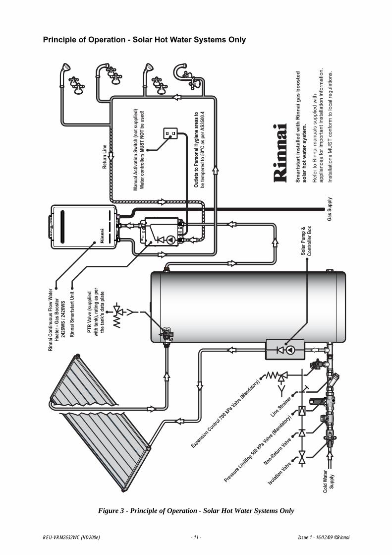
Principle of Operation - Solar Hot Water Systems Only
Figure 3 - Principle of Operation - Solar Hot Water Systems Only
Gas S
uppl
y
Retu
rn L
ine
Isolati
on ValveNon-Retu
rn Valve
Pressure
Limiting 50
0 kPa V
alve (M
andatory)
Line Stra
iner
Expansion Contro
l 700 k
Pa Valv
e (Mandato
ry)
Cold
Wat
erSu
pply
Smar
tsta
rt in
stal
led
with
Rin
nai g
as b
oost
ed
sola
r hot
wat
er s
yste
m.
Ref
er to
Rin
nai m
anua
ls s
uppl
ied
with
ap
plia
nces
for i
mpo
rtant
inst
alla
tion
info
rmat
ion.
Inst
alla
tions
MU
ST
conf
orm
to lo
cal r
egul
atio
ns.
Rinn
ai Sm
arts
tart
Unit
Manu
al Ac
tivat
ion
Switc
h (n
ot su
pplie
d)
Wat
er co
ntro
llers
MUS
T NO
T be
use
d!
Solar
Pum
p &
Cont
rolle
r Box
PTR
Valve
(sup
plied
wi
th ta
nk),
ratin
g as
per
th
e tan
k’s d
ata p
late
Rinn
ai Co
ntin
uous
Flo
w W
ater
He
ater
- Ga
s Boo
ster
��������
����24
26W
S�/�2
426W
S
Outle
ts to
Per
sona
l Hyg
iene a
reas
to
be te
mpe
red
to 50
°C as
per
AS3
500.4
REU-VRM2632WC (HD200e) - 11 - Issue 1 - 16/12/09 ©Rinnai
REU-VRM2632WC (HD200e) - 12 - Issue 1 - 16/12/09 ©Rinnai
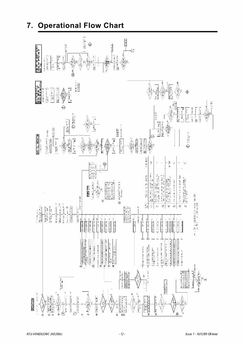
7. Operational Flow Chart

8. Operation Principles
Hot Water Operation
1. Ignition• Activate controllers (if fitted) and open the hot water tap (for full details regarding operation of water
controllers refer to the ‘Operation / Installation manual’ supplied with water heater).• When water fl ows thro ugh th e u nit, the wa ter flow s ensor rotates a nd sends an e lectrical ‘puls e’
signal to the Printed Circuit Board (PCB). This signal is proportional to the water flow rate.• The PCB sends electrical current to the combustion fan motor causing it to turn. The fan motor sends
an electrical pulse signal to the PCB. If fa n rotation is OK, the main solenoid a nd change oversolenoid valves open as required , the spark generator activates and the spark electrode ignites theburner.
2. Water Temperature / and Flow Control• The PCB will automatically control operation of the internal components to achieve the programmed
delivery temperature. When a high temperature rise is required, the PCB may cause the W ater FlowSensor to close partially resulting in a lower flow rate to achieve the programmed temperature. Thisis a necessary operational feature of the unit.
• When operating in ‘Bath Fill’ mode, the signal from the water flow sensor is also used by the PCB tocompute the volume of water that has been passed through the unit at any instant whilst the bath isfilling.
REU-VRM2632WC (HD200e) - 13 - Issue 1 - 16/12/09 ©Rinnai

3. Shut Down• When operating in ‘Bath Fill’ mode, the PCB causes the W ater Flow Sensor to close when the
programmed Bath Fill volume has passe d through the unit. Alternatively, flow is stopped when theuser closes the hot water tap.
• When water flow stops, the water flow sensor stops rotating and the pulse signal to the PCB stops.The PCB then causes the main solenoid and solenoid valves to close and the burner is extinguished.The combustion fan will continue to operate for some time to purge the combustion chamber.
REU-VRM2632WC (HD200e) - 14 - Issue 1 - 16/12/09 ©Rinnai
REU-VRM2632WC (HD200e) - 15 - Issue 1 - 16/12/09 ©Rinnai
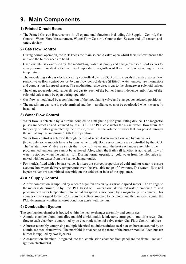
9. Main Components1) Printed Circuit Board• The Printed Cir cuit Board contro ls all operati onal functions incl uding Air Supply Control, Gas
Control, Water Flow Measurement, W ater Flow Co ntrol, Combus tion System and all sensors andsafety devices.
2) Gas Flow Control• During normal operation, the PCB keeps the main solenoid valve open whilst there is flow through the
unit and the burner needs to be lit.• Gas flow rate is c ontrolled by the modulating valve assembly and changeover sole noid va lves to
always ensure constant outlet wa ter temperature, regardless of flow ra te or incoming w atertemperature.
• The modulating valve is electronicall y controlle d b y th e PCB usin g sign als fro m th e water flowsensor, water flow control device, bypass flow control device (if fitted), water temperature thermistorsand combustion fan speed sensor. The modulating valve directs gas to the changeover solenoid valves.
• The changeover sole noid valves di rect gas to each of the burner banks independe ntly. Any of thesolenoid valves may be open during operation.
• Gas flow is modulated by a combination of the modulating valve and changeover solenoid positions.• The ma ximum gas rate is predetermined and the appliance ca nnot be overloaded whe n c orrectly
installed.
3) Water Flow Control• Water flow is detecte d by a turbine coupled to a magnetic pulse gene rating dev ice. Th e magnetic
pulses are detect ed and counted by th e P CB. The PCB calc ulates the e xact water flow from thefrequency of pulses generated by the turb ine, as well as the volume of water that has passed throughthe unit at any instant during ‘Bath Fill’ operation.
• Water flow control is achieved through the use of servo driven water flow and bypass valves. (Note: only some models have a by pass valve fitted). Both servo motors are controlled by the PCB.The ‘W ater Flow V alve’ re stricts the flow of water into the heat exchanger assembly if theprogrammed temperature cannot be achieved. Also, when the Bath F ill function is activated, flow ofwater is stopped when the bath is full. During normal operation, cold water from the inlet valve ismixed with hot water from the heat exchanger outlet.
• For models fitted with a bypass valve, it mixes the correct proportion of cold and hot water to ensureaccurate hot water delivery temperature over the available range of flow rates. The water flow andbypass valves are a combined assembly on the cold water inlet of the appliance.
4) Air Supply Control• Air for combustion is supplied by a centrifugal fan driven by a variable speed motor. The voltage to
the motor is determine d by the PCB based on water flow , delive red wate r tempera ture andprogrammed water temperature. The actual fan speed is monitored by a magnetic pulse counter. Thiscounter emits a signal to the PCB. From the voltage supplied to the motor and the fan speed signal, thePCB determines whether an error condition exists with the fan.
5) Combustion SystemThe combustion chamber is housed within the heat exchanger assembly and comprises:• A multi chamber aluminium alloy manifol d with multip le injectors, arranged in multiple rows. Gas
flow to each chamber is controlled by an electronic solenoid valve (refer ‘Gas Flow Control’ above).• A burner assembly comprising multiple identical modular stainless steel bunsen burners secured by an
aluminised steel framework. The manifold is attached to the front of the burner module. Each bunsenburner is supplied by two injectors.
• A combustion chamber. In tegrated into the combustion chamber front panel are the flame rod andignition electrode(s).

REU-VRM2632WC (HD200e) - 16 - Issue 1 - 16/12/09 ©Rinnai
10. Time ChartsNormal CombustionNote: By pass control device fitted.
Mis-Ignition / Flame Failure
Abnormal Pre-Purge (Air Supply/Exhaust Blockage)

11. Wiring Diagram
REU-VRM2632WC (HD200e) - 17 - Issue 1 - 16/12/09 ©Rinnai

12. Dip Switch Settings
Contact Rinnai for Dip Switch Settings.
REU-VRM2632WC (HD200e) - 18 - Issue 1 - 16/12/09 ©Rinnai

REU-VRM2632WC (HD200e) - 19 - Issue 1 - 16/12/09 ©Rinnai

REU-VRM2632WC (HD200e) - 20 - ©Rinnai
13. Diagnostic Points

14. Fault Finding
If there is a fault with the appliance, and controllers are installed, a numerical fault code may appear on thedigital display controller. If controllers are not installed, one may be fitted to find out the fault code. Faultfinding without controllers (and thus fault codes) is possible but more time consuming.
To diagnose and rectify faults, the Fault Finding Table is used as illustrated below:
Fault Finding TableDescribes possible faults
and error codes. (page 22)
Operational Flow Chart
(page 12)
Diagnostic Points TableSummarises running and standby electrical values
for all components. (page 18)
Wiring Diagram(page 17)
MaintenanceMonitor / Error
HistoryProvides accumulated
number of startups, combustion time, history of operational faults and
readout of electrical values whilst unit operational.
(page 30)
Component and Circuit Check
ProceduresDetailed information on
how to check all components.(page 23)
REU-VRM2632WC (HD200e) - 21 - Issue 1 - 16/12/09 ©Rinnai

Fault Finding Table
Code on Controller Fault Action
03Power interruption during Bathfill. Water will not flow when power restored.
1. Turn off all hot water taps.1. Press the ON/OFF button on a controller twice.
10Combustion fan current too high. Unit operates, then stops.
1. Check blockage of air intake/flue outlet.2. Check combustion fan.
11No ignition. Unit stops without flame igniting 1. Check gas supply
2. Check sparker unit3. Check gas valves
12
Flame Failure / Earth Leakage 1. Check gas supply2. Check flame rod3. Check earth wire lead4. Check water control
14
Thermal fuse and/or overheat switch activated. Unit operates, then stops.
1. Check thermal fuse2. Check overheat switchIMPORTANT- If thermal fuse or overheat switch were faulty :a. Check heater for damageb. Confirm “Gas Type” and “Combustion” dip switch settings.c. Confirm test point pressures .
16
Over temperature warning. Unit operates, then stops. 1. Confirm “Gas Type” and “Combustion” dip switch settings2. Confirm test point pressure 3. Check gas valves4. Check water flow sensor5. Check water flow servo6. Check heat exchanger outlet temperature thermistor7. Check hot water outlet temperature thermistor
32 Outlet water thermistor flow Check hot water outlet thermistor33 Heat exchanger thermistor error Check heat exchanger thermistor
52 Modulating solenoid valve fault. Unit stops without flame ignition.
Check modulating solenoid valve
61 Combustion fan rotation error Check combustion fan
65 Water flow control device error. Water flow is not controlled. Water temperature too low.
Check water flow servo
71 Solenoid valve circuit error. Unit does not operate. Check gas valves72 Flame rod circuit error. Unit does not operate. Check flame rod
-
Appliance does not operate at all. No display on the water controllers (if fitted).
1. Check power cord plugged in and supply turned on.2. Check power supply voltage.3. Check electrical fuse.4. Check transformer.5. Check gas valves6. Check sparker unit.7. Check earth leads and connections.8. Check for short circuits.9. Check water controller(s) - if fitted.
-
No combustion despite water control indicating that combustion is occuring - if water controller(s) fitted)
1. Check water flow sensor.2. Check flame rod.3. Check heat exchanger outlet thermistor. (REU-V2630 models only)4. Check hot water outlet thermistor.5. Check combustion fan.6. Check the sparker unit.7. Check gas valves.8. Check thermal fuse.9. Check overheat switch.IMPORTANT - If thermal fuse or overheat switch were faulty:a) check heater for damage;b) confirm “Gas Type” and “Combustion” dip switch settings;c) confirm test point pressure.
-Combustion stops during operation. 1. Check gas supply
2. Check flame rod3. Check earth leads and connections.
-
Cannot adjust the hot water temperature via the controller(s) - only if controller(s) fitted.
1. Check hot water outlet thermistor.2. Check heat exchanger outlet thermistor.3. Check gas valves4. Check water flow servo.5. Check bypass servo. (REU-VM2630WC/WD only)
-Anti-frost heater does not operate. 1. Check anti-frost heater components
2. Check frost sensing switch
REU-V2426WB /REU-V2426WS /REU-V2626WG /REU-VM2630WC /REU-VM2630WD - 22 - Issue 1 - 16/12/09 ©Rinnai

15. Component and Circuit Checks
1. Combustion Fan Circuit
Check the Motor
Check the combustion fan if the error indicator displays “61”.
Measure voltages between Black and Red of the PCB connector (A1).
Normal: DC6~45V (when fan ON)DC0V (when fan OFF)If normal proceed to check the rotation sensorFaulty: Replace PCB
Check for the Fan Rotation Sensor
a.) Measure voltages between Black and Yellow of connector (A1).Normal: DC11~13V If normal proceed to b.).Faulty: Replace PCB.
b.) Measure voltages between Black and White of connector (A1).Normal: DC5~10V If normal proceed to Sparker Circuit 2.Faulty: Replace Combustion Fan.
2. Sparker Circuit
a.) Measure voltages between Grey and Grey of connector (F6).
Normal: AC90~110VIf normal, proceed to b.).Faulty: Replace PCB.
b.) Disconnect connector (J6) and measure resistance between both terminals of the sparker.
Normal: 1MIf not sparking, adjust or replace ignition plug.Faulty: Replace Sparker.
REU-VRM2632WC (HD200e) - 23 - Issue 2 - 16/12/09 ©Rinnai

3a.Main Solenoid Valve (SV0) Circuit
Check the main solenoid if error indicator “11” is displayed.
a.) Disconnect Main Solenoid connector (E1) and measure resistance between Pink and BlackNormal: 1.7~2.1kIf normal, proceed to b.).Faulty: Replace Main Solenoid.
b.) Measure voltage between Pink-Black of Main Solenoid connector.
Normal: DC80~100VIf normal, proceed to Solenoid Valve SV1 (E2) Faulty: Replace PCB.
3b.Solenoid Valve 1 (SV1) Circuit
Check Solenoid 1 if error indicator “11” is displayed.
a.) Disconnect Solenoid 1 connector (E2) and measure resistance between Yellow and Black.
Normal: 1.7~2.1kIf normal, proceed to b.).Faulty: Replace Solenoid 1.
b.) Measure voltage between Yellow and Black of Solenoid 1 connector.
Normal: DC80~100VIf normal, proceed to Solenoid Valve 2 (SV2) CircuitFaulty: Replace PCB.
3c. Solenoid Valve 2 (SV2) Circuit
a.) Disconnect Solenoid Valve 2 connector (E3) and measure resistance between Blue and Black.
Normal: 1.7~2.1kIf normal,, proceed to b.Faulty: Replace Solenoid Valve 2.
b.) Measure voltage between Blue and Black of Solenoid Valve connector.
Normal: DC80~100VIf normal, proceed to Thermal fuse Circuit.Faulty: Replace PCB.
REU-VRM2632WC (HD200e) - 24 - Issue 2 - 16/12/09 ©Rinnai

3d.Valve Circuit
a.) Disconnect Solenoid connector (E4), measure resistance between Brown and Black.
Normal: 1.7~2.0kIf normal, proceed to b.).Faulty: Replace Solenoid Valve 3.
b.) Measure voltage between Brown and Black of SV3 connector.
Normal: DC80~100VIf normal, proceed to Modulating valve circuit.Faulty: Replace PCB.
c.) Disconnect Modulating Valve fasten terminal and measure resistance between terminals.
Normal: 67~81If normal, proceed to b.).Faulty: Replace Modulating Valve.
d.) Measure voltage between Pink and Pink of Modulating Valve fasten terminal.
Normal: DC2~15VIf normal, proceed to c.).Faulty: Replace PCB.
e.) Check the gas secondary pressure change when set temperature on the remote control changes from 37 to 55°C.
Normal: If secondary pressure changes, go to Water Flow Servo Circuit.Faulty: Replace Modulating Valve.
4. Flame Rod Circuit
Check flame rod.
Disconnect flame rod terminal (C1), and re-operate.
“72” indicated:- Proceed to 3.“72” is not indicated:- check for electrical leaks from the flame rod.
Measure resistance between flame rod terminal (C1) and appliance earth.
Normal: >1MIf normal, replace PCB.Faulty: Replace flame rod.
a.) Remove the Flame Rod terminal (C1) repeat operation procedure, if 72 is displayed again check the Hot water outlet thermistor.If 72 is not displayed check current leakage from the Flame Rod.
b.) Measure voltage between body earth and Flame Rod terminal (C1).
Normal: Voltage AC5~150VIf normal, replaced PCBFaulty: Replace Flame Rod.
c.) Check if the Flame Rod is securely fitted.
Normal: replace the PCBFaulty: Adjust the fitting of the Flame Rod
REU-VRM2632WC (HD200e) - 25 - Issue 2 - 16/12/09 ©Rinnai

4. Earth Lead
Confirm the E arth Lead connection is secure (at round terminal), and check for broken or shortcircuits in the lead.
If normal, check other possible causes for flame failure (is gas valve open?, is the filter blocked? etc.).If faulty, tighten the earth lead, PCB, power cord and surge arrester.
5. Thermal Fuse Circuit
Check the Thermal Fuse.
Disconnect relay connector (F1,) measure resistance between Red and Red.
Normal: < 1If normal, replace PCB.Faulty: Replace Thermal Fuse if after confirming there is no damage to the appliance.
6. Overheat Switch Circuit
Measure resistance between Overheat Switch terminals. Normal: < 1If normal, replace PCB.Faulty: Replace Overheat Switch.
Note: If Thermal fuse or Overheat Switch were faulty.
a.) Check heater for damage
b.) Confirm gas type and combustion dipswitch settings
c.) Confirm test point pressure.
7. Water Flow Sensor
a.) Measure voltage between Red - Black of relay connector (B4).
Normal: DC 11~13VIf normal, proceed to b.Faulty: Replace PCB.
b.) Measure voltage between Yellow - Black of relay connector (B4).
Normal: DC 4~7VIf normal, proceed to 2).Faulty: Replace water flow sensor.
Note: For controller readout of water flow whilst operational refer maintenance monitor. (Chapter 17 No. 1).
REU-VRM2632WC (HD200e) - 26 - Issue 2 - 16/12/09 ©Rinnai

8. Water Flow Servo Circuit
a.) Disconnect relay connector (B2), and measure voltage between Red and Blue on water flow servo.
Normal: 10~30If normal: proceed to b.).Faulty: Replace Water Flow Servo and Water Flow Sensor.
b.) Disconnect relay connector (B2), and measure voltage between Orange (+) and Grey (-) on PCB unit side.
Normal: DC11~13VIf Normal: proceed to c.).Faulty: Replace PCB unit.
c.) Measure voltage between Brown and Grey with relay connector (B2) connected (with no water flowing, water flow servo fully open).
Normal: < DC4~6VFaulty: Replace Water Flow Servo and Water Flow Sensor.
d.) Measure voltage between Yellow and Grey with relay connector (B2) connected (with no water flowing, water flow servo fully open).
Normal: < DC1.0VFaulty: Replace Water Flow Servo and Water Flow Sensor.
9. Heat Exchanger Outlet Thermistor Circuit
Check Heat Exchanger Thermistor if error code “33” is displayed.
Disconnect relay connector (B6) and measure resistance between White -White.
Circuit break: Resistance >1MShort circuit: Resistance > 1 Normal: Check Heat exchanger outlet thermistorFaulty: Replace heat exchanger outlet thermistor.
Note: For controller readout of thermistor temperature whilst operational refer maintenance monitor.
REU-VRM2632WC (HD200e) - 27 - Issue 2 - 16/12/09 ©Rinnai

10. Hot Water Outlet Thermistor Circuit
Check Hot Water Thermistor if error code “32” is displayed.Disconnect relay connector (B5) and measure resistance White - White.
When disconnected: Resistance > 1 MWhen short circuit: Resistance > 1 Normal: Check Heat Exchanger Outlet Thermistor.Faulty: Replace hot water outlet thermistor.
Note: For controller readout of thermistor temperature whilst operational refer maintenance monitor. (Chapter 17, No. 2).Disconnect relay connector (E1) and measure resistance White-White.
11.Surge Protector
Check the fuse.
a.) Unplug the power plug.
b.) Check whether or not the fuse (3A) x 2 has blown by measuring the resistance.
Normal: <1If normal go to step Electrical Fuse 13.Faulty: Replace fuse/s (3Ax2). Check for a short next time it’s turned off.
12.Electrical Fuse
a.) Measure voltage between blue and brown on the connector (F4)
Normal :AC 207~264VIf normal proceed to b.Faulty: Check if voltage on the fuse terminal is AC207~264V
b.) Measure voltage between white and white on the (F5).
Normal: AC207~264V.Faulty: replace surge protecter unit.
b.) Measure the voltage of the connector on the PCB.
Normal: Between Brown and Grey AC 30~50VBetween Yellow and Grey AC 180~220VIf normal, proceed to c.).Faulty: Replace transformer.
c.) Measure voltage between White and Black of connector (F) on PCB.
Normal: AC 90~110VIf normal, proceed to 4.Faulty: Replace transformer.
Note) The above transformer voltages are measured while the appliance is in standby mode - not while it is operating.
Normal Temp. 15oC 30oC 45oC 60oCResistance k 6.4~7.8 k 3.6~4.5 k 2.2~2.7 k
REU-VRM2632WC (HD200e) - 28 - Issue 2 - 16/12/09 ©Rinnai

13. Bypass Servo Circuit 15.
a.) Disconnect relay connector (G1) and measure resistance.
If normal, proceed to b.).Faulty: Replace PCB.
b.) Measure working voltage while relay connector (G1) is connected.
Faulty: Replace Bypass Servo.
14.Remote Control
Check the voltage between the 2-core remote control cable.
Measure the voltage between terminals on the remote control terminal (D1).
Normal: DC 11~13VIf normal, replace the remote control after confirming that the cable hasn’t been damaged or shorted.Faulty: Because normal voltage is not given due a short circuit, despite the PCB being in normal state, check Water Flow Servo circuit.If solution is not given from the above replace PCB.
Normal CN Wire Colour Value
G1
Br - WO - WY - WR - WGND
15~35
Normal CN Wire Colour Value
G1
Br - WO - WY - WR - WGND
DC 2~6V
REU-VRM2632WC (HD200e) - 29 - Issue 2 - 16/12/09 ©Rinnai

16. Maintenance Monitor / Error History
Wireless Controllers
M
MMaintenance Function - Wireless Controller Transceiver
1.) Press maintenance button once.
2.) Temperature light (orange) will illuminate & the Led display will show current water temperature in heat exchanger.
3.) Press maintenance button again.‘Volume’ light - (orange) will illuminate. Led display to show l/minimum water flow through Infinity.
4.) Press maintenance button again and the previous 10 error codes will be displayed.
First number shown on Led display will be 1 - followed by error code then 2 and the error code.If error code reads — —, it means there was no error recorded.Press maintenance button again to return to transceiver to normal mode.
This feature is available where the appliances are co nnected with a deluxe controller Thi s will enabl eservice personnel to locate the maintenance history and faulty components, with the appliance in operation.
Note: When the maintenance information, error history is shown, use only one controller. If two or morewater controllers are used at the same time, it may not operate correctly.
To display Maintenance Information
1.)With the controller in the "OFF" position press the Water Temperature "DOWN" (Cooler) button while holding the "ON/OFF" button to activate the maintenance monitor. Press the "ON/OFF" button a second time to set the controller in the "ON" mode. This feature can now be used with the appliance in operation.
2.) The maintenance number will be shown in the Water Temperature display.
3.) Data will be shown in the Clock display.
1. To select the required maintenance number, press the Water Temperature "UP" and "DOWN" buttons.
Entry
Controllers
MC No. 1 No. 2 No. 3
Max Temp. Maintenance
Temp. VolumeOn/Off
Water Heater
REU-VRM2632WC (HD200e) - 30 - Issue 1 - 16/12/09 ©Rinnai

*Note 1 Fan Frequency rpm Conversion(rpm) = (Hz) x15
*Note 2 Water Control Connections
*Note 3 Water Flow Servo Positioning
Display Monitor Contents No. Contents Units Data Range01 Water flow sensor recognition flow
(Example 123 = 12.3L/min).0.1L/min 0~400
02 Hot water Outlet thermistor temperature
(Example 20 = 20 C)C 0~999
03 Hot water combustion time(Example 6 = 600 hours)
100 hours 000~999
04 Hot water operation frequency(Example 6 = 600 Operations)
100 0~999
05 Hot water fan frequency Hz pulses/sec 0~999 *Note 1
06 water control connection none 0 or 1 *Note 2
Bathroom water
Additional controller Kitchen controller
“0” “1”
Controls connected
Display
No “0”
Yes “1”
07 Water flow servo present recognising positioning
None 0~2 *Note 3
Servo Position Open Centre ClosedDisplay “1” “0” “2”
08 Inlet water temperature(PCB recognition value)
(Example 25 = 25 C)
C 0~999
09 Hot water fan current flow value(Example 6 x 10 = 60 mA)
10 mA 0~999
10 Bath fill amount (this counts the litres during bath fill operation).
Litres 0~999
11 Heat exchanger exit thermistor
temperature (Example 55 = 55 C)C 0~999
12 Bypass servo present recognition positioning(Example 0 = Closed
250 = Half open 500 = Open
Degrees 0~500
REU-VRM2632WC (HD200e) - 31 - Issue 1 - 16/12/09 ©Rinnai

To return to normal operation• Press the ON/OFF button again while holding down the Wa ter Temperature "DOWN" (Coole r)
button.
To return to normal operation
• Press the ON/OFF button again while holding the Water Temperature “UP” (Hotter) button.
• This feature will automatically shut down after 3 minuets.
Error History
To Display Error Memory (History)(This feature will show the last 10 faults in sequence) 1. Turn off at the ON/OFF button. (This can be done during
operation)
2. Press the ON/OFF button while holding the Water Temperature "UP" (Hotter) button.
• The Sequence will be shown in the Water Temperature display.
• Error Code will be shown in the Clock display. (See service Manual for error codes).
• Where there are less than a total of 9 errors, "FFF" or " - - " will be displayed in the Clock display.
REU-VRM2632WC (HD200e) - 32 - Issue 1 - 16/12/09 ©Rinnai

17. Gas Pressure Setting Procedure
Refer seperate Rinnai document behind front cover of appliance.
18. Gas Conversion Procedure
Refer seperate document available from Rinnai.
REU-VRM2632WC (HD200e) - 33 - Issue 1 - 16/12/09 ©Rinnai

19. Dismantling for Service
240 Volt potential exposure. Isolate the appliance and reconfirm with a neon screwdriver or multimeter.
Item Page
1. Removal of the Front Panel . . . . . . . . . . . . . . . . . . . . . . . . . . . . . . . . . . . . . . .36
2. Removal of the PCB Unit . . . . . . . . . . . . . . . . . . . . . . . . . . . . . . . . . . . . . . . . .36
3. Removal of the Water Flow Sensor, Servo and Bypass Servo . . . . . . . . . . . . .36
4. Removal of the Bypass Servo -. . . . . . . . . . . . . . . . . . . . . . . . . . . . . . . . . . . . .36
5. Removal of the Manifold and Burner unit . . . . . . . . . . . . . . . . . . . . . . . . . . . . .38
6. Removal of the Gas Control . . . . . . . . . . . . . . . . . . . . . . . . . . . . . . . . . . . . . . .38
7. Removal of Flame rod and Spark plug . . . . . . . . . . . . . . . . . . . . . . . . . . . . . . .39
8. Removal of Outgoing Water Thermistor . . . . . . . . . . . . . . . . . . . . . . . . . . . . . .39
9. Removal of Heat Exchanger Thermistor . . . . . . . . . . . . . . . . . . . . . . . . . . . . . .39
10. Removal of Bypass Servo -. . . . . . . . . . . . . . . . . . . . . . . . . . . . . . . . . . . . . . . .40
11. Removal of Anti Frost Switch . . . . . . . . . . . . . . . . . . . . . . . . . . . . . . . . . . . . . .40
12. Removal of Anti Frost heater . . . . . . . . . . . . . . . . . . . . . . . . . . . . . . . . . . . . . .41
13. Removal of the Fan Motor. . . . . . . . . . . . . . . . . . . . . . . . . . . . . . . . . . . . . . . . .41
14. Removal of Heat Exchanger . . . . . . . . . . . . . . . . . . . . . . . . . . . . . . . . . . . . . . .42
15. Removal of Thermal Fuse. . . . . . . . . . . . . . . . . . . . . . . . . . . . . . . . . . . . . . . . .43
Unless otherwise stated, re-assembly is the reverse of dismantling.
REU-VRM2632WC (HD200e) - 35 - Issue 2 - 16/12/09 ©Rinnai
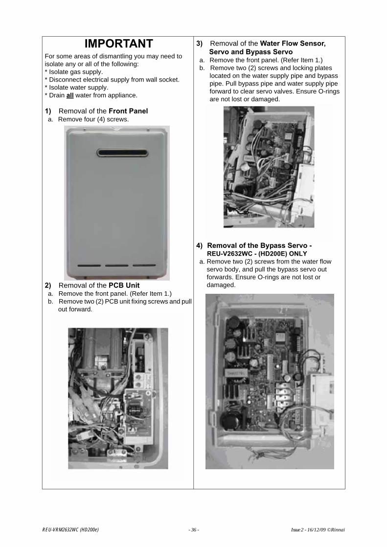
IMPORTANTFor some areas of dismantling you may need to isolate any or all of the following:* Isolate gas supply.* Disconnect electrical supply from wall socket.* Isolate water supply.* Drain all water from appliance.
1) Removal of the Front Panela. Remove four (4) screws.
2) Removal of the PCB Unita. Remove the front panel. (Refer Item 1.)b. Remove two (2) PCB unit fixing screws and pull
out forward.
3) Removal of the Water Flow Sensor, Servo and Bypass Servo
a. Remove the front panel. (Refer Item 1.)b. Remove two (2) screws and locking plates
located on the water supply pipe and bypass pipe. Pull bypass pipe and water supply pipe forward to clear servo valves. Ensure O-rings are not lost or damaged.
4) Removal of the Bypass Servo - REU-V2632WC - (HD200E) ONLY
a. Remove two (2) screws from the water flow servo body, and pull the bypass servo out forwards. Ensure O-rings are not lost or damaged.
REU-VRM2632WC (HD200e) - 36 - Issue 2 - 16/12/09 ©Rinnai

5) Removal of Sparker
a. Remove sparker b. Remove 3 pin connectorc. Remove high tension cord
6) Removal of the Manifold and Burner unit
a. Remove high tension cord and flame rod.b. Remove 2 pin connection of the solenoid valvec. Remove manifold.
REU-VRM2632WC (HD200e) - 37 - Issue 2 - 16/12/09 ©Rinnai
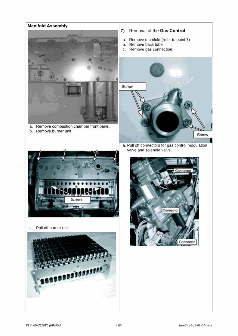
Manifold Assembly
a. Remove combustion chamber front panel.b. Remove burner unit.
c. Pull off burner unit
7) Removal of the Gas Control
a. Remove manifold (refer to point 7)b. Remove back tubec. Remove gas connection.
a. Pull off connectors for gas control modulation valve and solenoid valve.
REU-VRM2632WC (HD200e) - 38 - Issue 2 - 16/12/09 ©Rinnai

Gas Control
8) Removal of Flame rod and Spark plug
a. Remove flame rod terminal and tighten sparker lead.
b. Remove flame rod and spark plug.
a. Remove of High Tension lead
9) Removal of Outgoing Water Thermistor
a. Remove thermistor fixing screw.b. Remove 2 pin connection outgoing water
thermistor
Heat Exchanger Thermistor
10) Removal of Heat Exchanger ThermistorREU-V2632WC (HD200E) ONLY
a. Remove thermistor holderb. Remove 2 pin connector
REU-VRM2632WC (HD200e) - 39 - Issue 2 - 16/12/09 ©Rinnai

11) Removal of Bypass Servo - REU-V2632WC - (HD200E) ONLY
a. Remove fan motor (Refer to point 16)b. Remove 3 pin connectorc. Remove 2 pin connectord. Remove 6 pin connector and 5 pin connectore. Remove bracket for water connection tube.
f. Removal of inlet water connection
g. Remove bypass servo and water flow servoh. Remove fitting screws of bypass servo
i. Flow sensor and water flow servo
12) Removal of Anti Frost Switch
a. Remove 2 pin connection for anti frost switchb. Remove Anti Frost switch
c. Anti Frost switch
REU-VRM2632WC (HD200e) - 40 - Issue 2 - 16/12/09 ©Rinnai

13) Removal of Anti Frost heater
a. Remove 2 pin connection of Anti Frost heaterb. Remove bracket on hot water connection.c. Remove Anti Frost heater.
14) Removal of the Fan Motor
a. Remove 4 pin connector to fan motor.b. Remove 2 pin connector of solenoid valve.
c. Remove fan motor screws (x 2)
d. Remove fan motor assembly by sliding forward
e. Remove fan motor from housing via. 3 screws
REU-VRM2632WC (HD200e) - 41 - Issue 2 - 16/12/09 ©Rinnai

15) Removal of Heat Exchanger
a. Remove PCBb. Remove fan motorc. Remove 2 pin connector of thermal fused. Remove flame rod terminal of high tension corde. Remove anti frost heater switchf. Remove 2 pin connectorg. Remove 3 pin connectorh. Remove fixing screws of the heat exchanger
uniti. Remove heat exchanger screws
j. Remove Bypass tube - REU-V2632WC (HD200E) ONLY
k. Pull out heat exchanger screwsREU-V2632WC - (HD200E) - Heat Exchanger shown
l. Remove manifold and burner unit.m. Remove thermal fuse, over heat switch,
sparker, hex thermister and back pressure joint.
REU-V2632WC - (HD200E) - Heat Exchanger shown
REU-VRM2632WC (HD200e) - 42 - Issue 2 - 16/12/09 ©Rinnai

16) Removal of Thermal Fusea. Remove heat exchanger.b. Remove Thermal Fuse.
After removal of thermal fuse fitting procedure is as follows:
Heat Exchanger Front
Heat Exchanger Left
Heat Exchanger Right
Heat Exchanger Right
REU-VRM2632WC (HD200e) - 43 - Issue 2 - 16/12/09 ©Rinnai

20. Parts List
NOTE: Some Part details may have changed since publication of this manual. Contact Rinnai to confirm spare parts details before ordering.
NO Part Name RA Part No 11 Digit Code Qty
001 OUTER CASE 92095893 014-481-000 1002 BRKT WALL 92093377 106-329-000 2004 Panel, Conn. Reinf. 044-140-000 1005 Shield, Heat Insul. 030-915-000 1006 PANEL FRONT 92095894 019-4064000 1007 SEAL PANEL FRONT TOP 92086909 580-453-000 1008 Sealing, Body side 92063361 510-990-000 2009 INF20 CABLE ENTRY (NEW) 92073352 106-104-000 1010 SEAL HARNESS EASY CONN 92099984 580-0105000 2011 HARNESS EASY CONN 92099986 106-641-000 1012 CLIP SUPPORT 92095896 538-840-000 1013 Packing 510-893-000 1014 Pouch 600-051-000 1100 GAS CONTROL 92086736 120-0016000 1101 SCREW TEST POINT 92099956 501-275-005 3102 INLET GAS 3/4 92081587 106-290-000 1103 BURNER ASSY 92092212 000-059-000 1103 Burner Unit Assy 92099904 000-155-000 1104 Burner Case, Fr panel 098-902-000 1105 Burner Case, Btm plate 005-137-000 1106 Gasket, Bnr Case Fr 580-440-000 1107 Burner, Low Nox Bunsen Assy. 157-090-000 16108 Burner Case, Back plate 098-904-000 1109 Damper 92099906 140-597-000 1109 Damper 92099908 140-736-E00 1110 MANIFOLD LP 92094318 101-705-000 1110 MANIFOLD NG 92095897 101-747-000 1111 Sealing, Combust. 580-547-000 1112 Sealing, Lwr Comb. Cmbr 580-569-000 1114 Front plate, Comb. Cmbr Assy. 019-1337000 1116 ELECTRODE 92086974 202-156-000 1117 ELECTRODE FR 92095598 202-215-000 1118 PACKING ELECTRODE 92087015 580-0390000 1119 ELECTRODE HOLDER RH 92087006 580-505-000 1120 Gasket, Comb. Cmbr fr panel 580-998-000 1125 FAN COMB 92095224 222-610-000 1126 Fan Casing, Assy 098-2183000 1127 CONNECTING COMB FAN 92098870 106-320-000 1128 PACKING FAN CONECTING 92098888 580-338-000 1129 MOTOR FAN COMB 92095899 222-559-000 1
REU-VRM2632(65)WC-AK
REU-VRM2632WC (HD200e) - 44 - Issue 1 - 16/12/09 ©Rinnai

NO Part Name RA Part No 11 Digit Code Qty
REU-VRM2632(65)WC-AK
135 EXHAUST FLUE 92092634 055-760-000 1137 Sealing, Flue spigot 580-0023000 1138 Sealing, Flue term. 580-835-000 1140 HEAT EXCH 92093550 314-733-000 1400 INLET WATER 3/4 92095901 333-483-000 1401 WATER FLOW SENSOR 92095902 301-157-000 1402 RECTIFIER WATER 92093552 330-107-000 1403 BYPASS SERVO ASSY 92087072 301-158-000 1404 Bracket, Stop 512-401-000 2405 Band, Water filter plug 553-119-000 1406 FILTER WATER 0 LARGE 92083773 196-062-000 1408 OUTLET WATER 3/4 92093806 333-386-000 1409 Bracket, Stop 538-515-000 1410 Band, Drain valve 553-043-000 1411 Valve Assy, Drain 92099944 337-152-000 1412 Cover, Water flow servo 098-1445000 1700 Electric Unit Assembly 92099918 210-909-000 1701 SURGE ARRESTOR 92093699 210-605-000 1702 Cover, PCB side 098-1868000 1703 Cover, PCB front (RA) 098-1869000 1704 THERMISTOR 1 92095030 233-246-000 1705 Bracket, PCB 537-0060000 1706 SPARKER 92095026 261-157-000 1707 Lead, High tension 92099920 203-869-000 1708 SLEEVE ELECTRODE 92087030 518-035-000 1709 THERMISTOR 2 VM2630WC/WD 92095031 233-247-000 1710 BRKT THERMISTOR 92086388 508-836-000 1711 Clip, Thermal fuse 537-505-000 5712 SWITCH THERMAL 92097187 234-444-000 1713 HEATER A-FROST 92095903 235-391-000 1714 HEATER WATER FLOW 92092262 235-369-000 1715 Bracket, Ignitor 537-0822000 1716 BRKT HEATER 92093301 538-493-000 2717 BRKT HEATER A 92096123 537-155-000 1718 BRKT HEATER B 92096225 537-0440000 1720 ELEC CORD 92089051 206-226-000 1721 HARNESS FUSE 92094015 290-1300000 1723 HARNESS RELAY 92099985 290-1301000 1724 Harness, Sensor 92099924 290-1707000 1725 FUSE THERMAL 92092189 232-191-000 1
REU-VRM2632WC (HD200e) - 45 - Issue 1 - 16/12/09 ©Rinnai

NO Part Name RA Part No 11 Digit Code Qty
REU-VRM2632(65)WC-AK
726 SENSOR MR 92099988 243-133-000 1727 HARNESS SPARKER 92099989 290-1303000 1729 HARNESS REMOTE CONTROL 92099961 290-1288000 1730 HARNESS SURGE ARREST 92095129 290-1304000 1731 HARNESS RELAY 92095033 290-1289000 1733 RELAY VM2630WC/WD 92095032 210-810-000 1810 O RING THERMISTOR 92062249 520-209-010 2812 O RING (S4) TEST POINT 90195165 520-300-010 3813 O RING IN/OUT WATER 92071182 520-049-010 2814 O RING HEAT EXCH 92062199 520-048-010 2815 O RING HEAT EXCH 92062207 520-193-010 2816 O RING 2010 2402 92062348 520-281-010 1817 O RING GAS CON 2010 92072859 520-043-010 1818 O RING GAS CONTROL 92096502 580-180-000 2
REU-VRM2632WC (HD200e) - 46 - Issue 1 - 16/12/09 ©Rinnai

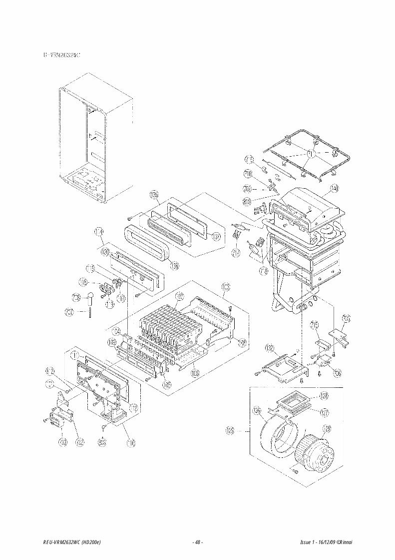
21. Exploded Diagrams
NOTE: Some Part details may have changed since publication of this manual. Contact Rinnai to confirm spare parts details before ordering.
REU-VRM2632WC (HD200e) - 47 - Issue 1 - 16/12/09 ©Rinnai
REU-VRM2632WC (HD200e) - 48 - Issue 1 - 16/12/09 ©Rinnai

REU-V2626WG-AK / REU-V2 426WB-AK / REU-V2426WS
REU-VRM2632WC (HD200e) - 49 - Issue 1 - 16/12/09 ©Rinnai

REU-VRM2632WC (HD200e) - 50 - Issue 1 - 16/12/09 ©Rinnai
51 RA TSD 07-020 Service Manual Issue1 - 16/12/09
Head Office
10-11 Walker Street,Braeside, Victoria 3195P.O. Box 460Tel: (03) 9271 6625Fax: (03) 9271 6622
National Help Lines
Spare Parts & Technical InfoTel: 1300 555 545*Fax: 1300 300 141**Cost of a local call Higher from mobile or public phones.
Hot Water Service LineTel: 1800 000 340
Australia Pty. Ltd. ABN 74 005 138 769 Internet: www.rinnai.com.au E-mail: [email protected]
Rinnai has a Service and Spare Parts network with personnel who are fully trained and equipped to give the best service on your Rinnai appliance. If your appliance requires service, please call our Hot Water Service Line. Rinnai recommends that this appliance be serviced every 3 years.
CONTACT INFORMATION


