35
Diesel Injection Pump MITSUBISHI PAJERO 4M41 ENGINE COMMON RAIL SYSTEM (CRS) March, 2007 00400597E SERVICE MANUAL
Diesel Injection Pump
MITSUBISHI PAJERO 4M41 ENGINE COMMON RAIL SYSTEM (CRS)
March, 2007
00400597E
SERVICE MANUAL

© 2007 DENSO CORPORATIONAll Rights Reserved. This book may not be reproducedor copied, in whole or in part, without the writtenpermission of the publisher.
Table of Contents
Table of Contents
Operation Section
1. PRODUCT APPLICATION INFORMATION1.1 Applicable Vehicle . . . . . . . . . . . . . . . . . . . . . . . . . . . . . . . . . . . . . . . . . . . . . . . . . . . . . . . . . . . . . . . . . . . . . . . 1-1
1.2 System Component Part Numbers . . . . . . . . . . . . . . . . . . . . . . . . . . . . . . . . . . . . . . . . . . . . . . . . . . . . . . . . . . 1-1
2. SUPPLY PUMP2.1 Outline . . . . . . . . . . . . . . . . . . . . . . . . . . . . . . . . . . . . . . . . . . . . . . . . . . . . . . . . . . . . . . . . . . . . . . . . . . . . . . . . 1-2
2.2 Suction Control Valve (SCV) . . . . . . . . . . . . . . . . . . . . . . . . . . . . . . . . . . . . . . . . . . . . . . . . . . . . . . . . . . . . . . . 1-3
2.3 Fuel Temperature Sensor . . . . . . . . . . . . . . . . . . . . . . . . . . . . . . . . . . . . . . . . . . . . . . . . . . . . . . . . . . . . . . . . . 1-5
3. RAIL3.1 Outline . . . . . . . . . . . . . . . . . . . . . . . . . . . . . . . . . . . . . . . . . . . . . . . . . . . . . . . . . . . . . . . . . . . . . . . . . . . . . . . . 1-6
3.2 Rail Pressure Sensor (Pc Sensor). . . . . . . . . . . . . . . . . . . . . . . . . . . . . . . . . . . . . . . . . . . . . . . . . . . . . . . . . . . 1-6
3.3 Pressure limiter . . . . . . . . . . . . . . . . . . . . . . . . . . . . . . . . . . . . . . . . . . . . . . . . . . . . . . . . . . . . . . . . . . . . . . . . . 1-7
4. INJECTOR (G2 TYPE)4.1 Outline . . . . . . . . . . . . . . . . . . . . . . . . . . . . . . . . . . . . . . . . . . . . . . . . . . . . . . . . . . . . . . . . . . . . . . . . . . . . . . . . 1-8
4.2 Characteristics. . . . . . . . . . . . . . . . . . . . . . . . . . . . . . . . . . . . . . . . . . . . . . . . . . . . . . . . . . . . . . . . . . . . . . . . . . 1-8
4.3 Construction . . . . . . . . . . . . . . . . . . . . . . . . . . . . . . . . . . . . . . . . . . . . . . . . . . . . . . . . . . . . . . . . . . . . . . . . . . . 1-9
4.4 QR Codes . . . . . . . . . . . . . . . . . . . . . . . . . . . . . . . . . . . . . . . . . . . . . . . . . . . . . . . . . . . . . . . . . . . . . . . . . . . . 1-10
5. OPERATION OF CONTROL SYSTEM COMPONENTS5.1 Engine Control System Diagram . . . . . . . . . . . . . . . . . . . . . . . . . . . . . . . . . . . . . . . . . . . . . . . . . . . . . . . . . . . 1-11
5.2 Engine ECU (Electronic Control Unit) . . . . . . . . . . . . . . . . . . . . . . . . . . . . . . . . . . . . . . . . . . . . . . . . . . . . . . . 1-12
5.3 Cylinder Recognition Sensor (TDC) . . . . . . . . . . . . . . . . . . . . . . . . . . . . . . . . . . . . . . . . . . . . . . . . . . . . . . . . 1-18
5.4 Boost Pressure Sensor . . . . . . . . . . . . . . . . . . . . . . . . . . . . . . . . . . . . . . . . . . . . . . . . . . . . . . . . . . . . . . . . . . 1-19
5.5 Mass Airflow Meter . . . . . . . . . . . . . . . . . . . . . . . . . . . . . . . . . . . . . . . . . . . . . . . . . . . . . . . . . . . . . . . . . . . . . 1-20
5.6 Electronic Control Throttle . . . . . . . . . . . . . . . . . . . . . . . . . . . . . . . . . . . . . . . . . . . . . . . . . . . . . . . . . . . . . . . . 1-21
6. FUEL INJECTION CONTROL6.1 Outline . . . . . . . . . . . . . . . . . . . . . . . . . . . . . . . . . . . . . . . . . . . . . . . . . . . . . . . . . . . . . . . . . . . . . . . . . . . . . . . 1-22
6.2 Fuel Injection Quantity Control . . . . . . . . . . . . . . . . . . . . . . . . . . . . . . . . . . . . . . . . . . . . . . . . . . . . . . . . . . . . 1-22
6.3 Other Controls . . . . . . . . . . . . . . . . . . . . . . . . . . . . . . . . . . . . . . . . . . . . . . . . . . . . . . . . . . . . . . . . . . . . . . . . . 1-24
7. OTHER SYSTEMS7.1 Outline . . . . . . . . . . . . . . . . . . . . . . . . . . . . . . . . . . . . . . . . . . . . . . . . . . . . . . . . . . . . . . . . . . . . . . . . . . . . . . . 1-26
7.2 Diesel Particulate Filter (DPF) System . . . . . . . . . . . . . . . . . . . . . . . . . . . . . . . . . . . . . . . . . . . . . . . . . . . . . . 1-26
8. DIAGNOSTIC TROUBLE CODES (DTC)8.1 About the Codes Shown in the Table . . . . . . . . . . . . . . . . . . . . . . . . . . . . . . . . . . . . . . . . . . . . . . . . . . . . . . . 1-27
8.2 Diagnostic Trouble Code Details . . . . . . . . . . . . . . . . . . . . . . . . . . . . . . . . . . . . . . . . . . . . . . . . . . . . . . . . . . . 1-27

Operation Section1–1
1. PRODUCT APPLICATION INFORMATION
1.1 Applicable Vehicle
1.2 System Component Part Numbers
Vehicle Manufac-
ture
Vehicle Name Engine Model Specification Destination Line Off Period
MITSUBISHI PAJERO 4M41 4WD (MT/AT) Europe, Australia Sep, 2006
Parts Name DENSO P/N Manufacturer P/N Remarks
Supply pump SM294000-034# 1460A003
Injector SM095000-576# 1465A054
Rail SM095440-064# 1465A034
Engine ECU
275800-468# 1860A699 Manual transmission vehi-cles only
275800-469# 1860A702 Automatic transmissionvehicles only
Boost pressure sensor 079800-779# 1865A035
Electronic control throttle 197920-002# 1450A033
Fuel temperature sensor 179730-002# MR547077
Mass air flow meter 197400-227# 1525A016
Exhaust gas temperature sensor 1 265600-145# 1587A013
Automatic transmissionvehicles only
Exhaust gas temperature sensor 2 265600-146# 1587A014
Exhaust gas temperature sensor 3 265600-147# 1587A015
Differential pressure sensor 104990-136# 1865A087
Absolute pressure sensor 104990-135# 0865A086
Temperature sensor for differential pres-sure sensor learning
170400-602# 1865A095
Electric-Vacuum Regulating Valve (E-VRV) for Variable Geometry Turbo(VGT)
139700-035# MR258166
Operation Section1–2
2. SUPPLY PUMP
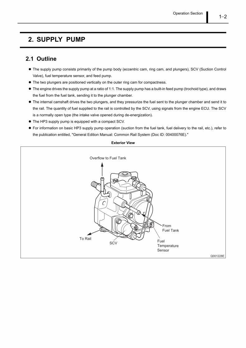
2.1 OutlineThe supply pump consists primarily of the pump body (eccentric cam, ring cam, and plungers), SCV (Suction Control
Valve), fuel temperature sensor, and feed pump.
The two plungers are positioned vertically on the outer ring cam for compactness.
The engine drives the supply pump at a ratio of 1:1. The supply pump has a built-in feed pump (trochoid type), and draws
the fuel from the fuel tank, sending it to the plunger chamber.
The internal camshaft drives the two plungers, and they pressurize the fuel sent to the plunger chamber and send it to
the rail. The quantity of fuel supplied to the rail is controlled by the SCV, using signals from the engine ECU. The SCV
is a normally open type (the intake valve opened during de-energization).
The HP3 supply pump is equipped with a compact SCV.
For information on basic HP3 supply pump operation (suction from the fuel tank, fuel delivery to the rail, etc.), refer to
the publication entitled, "General Edition Manual: Common Rail System (Doc ID: 00400076E)."
Exterior View
Q001228E
From
Fuel Tank
Overflow to Fuel Tank
To RailFuel
TemperatureSensor
SCV
Operation Section1–3
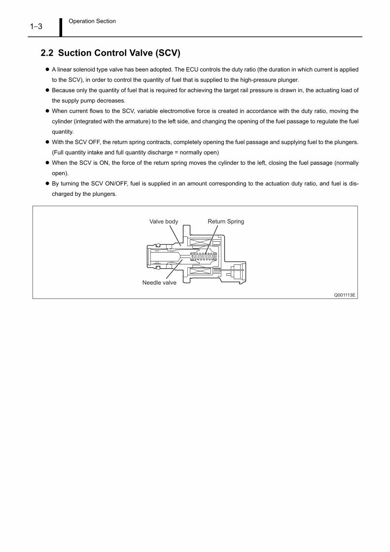
2.2 Suction Control Valve (SCV)A linear solenoid type valve has been adopted. The ECU controls the duty ratio (the duration in which current is applied
to the SCV), in order to control the quantity of fuel that is supplied to the high-pressure plunger.
Because only the quantity of fuel that is required for achieving the target rail pressure is drawn in, the actuating load of
the supply pump decreases.
When current flows to the SCV, variable electromotive force is created in accordance with the duty ratio, moving the
cylinder (integrated with the armature) to the left side, and changing the opening of the fuel passage to regulate the fuel
quantity.
With the SCV OFF, the return spring contracts, completely opening the fuel passage and supplying fuel to the plungers.
(Full quantity intake and full quantity discharge = normally open)
When the SCV is ON, the force of the return spring moves the cylinder to the left, closing the fuel passage (normally
open).
By turning the SCV ON/OFF, fuel is supplied in an amount corresponding to the actuation duty ratio, and fuel is dis-
charged by the plungers.
Q001113E
Valve body
Needle valve
Return Spring
Operation Section1–4
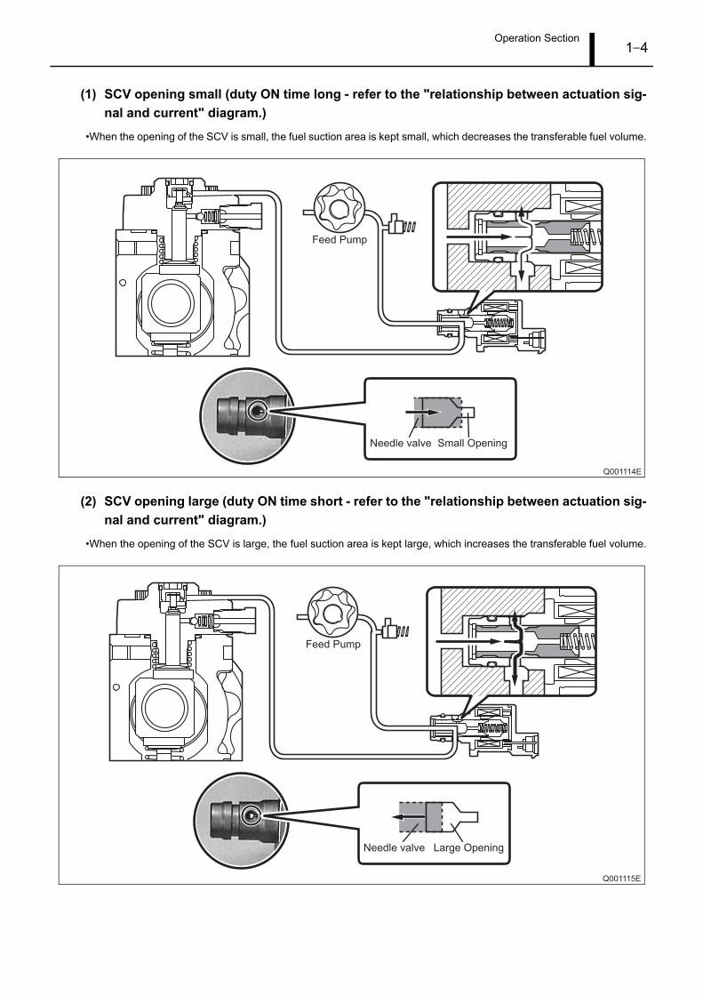
(1) SCV opening small (duty ON time long - refer to the "relationship between actuation sig-nal and current" diagram.)
•When the opening of the SCV is small, the fuel suction area is kept small, which decreases the transferable fuel volume.
(2) SCV opening large (duty ON time short - refer to the "relationship between actuation sig-nal and current" diagram.)
•When the opening of the SCV is large, the fuel suction area is kept large, which increases the transferable fuel volume.
Q001114E
Feed Pump
Needle valve Small Opening
Q001115E
Feed Pump
Needle valve Large Opening
Operation Section1–5
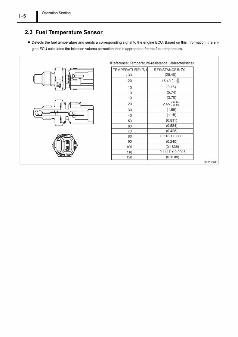
2.3 Fuel Temperature SensorDetects the fuel temperature and sends a corresponding signal to the engine ECU. Based on this information, the en-
gine ECU calculates the injection volume correction that is appropriate for the fuel temperature.
Q001237E
<Reference: Temperature-resistance Characteristics>
RESISTANCE(°C) (k )TEMPERATURE
- 30 (25.40)
(9.16)
(1.66)
(1.15)
(0.811)
(0.584)
(0.428)
(0.240)
(0.1836)
(0.1108)
(5.74)
(3.70)
15.40 + 1.29- 1.20
+ 0.14- 0.132.45
0.318 ± 0.008
0.1417 ± 0.0018
- 20
- 10
10
20
30
40
50
60
70
80
90
100
110
120
0
Operation Section1–6
3. RAIL
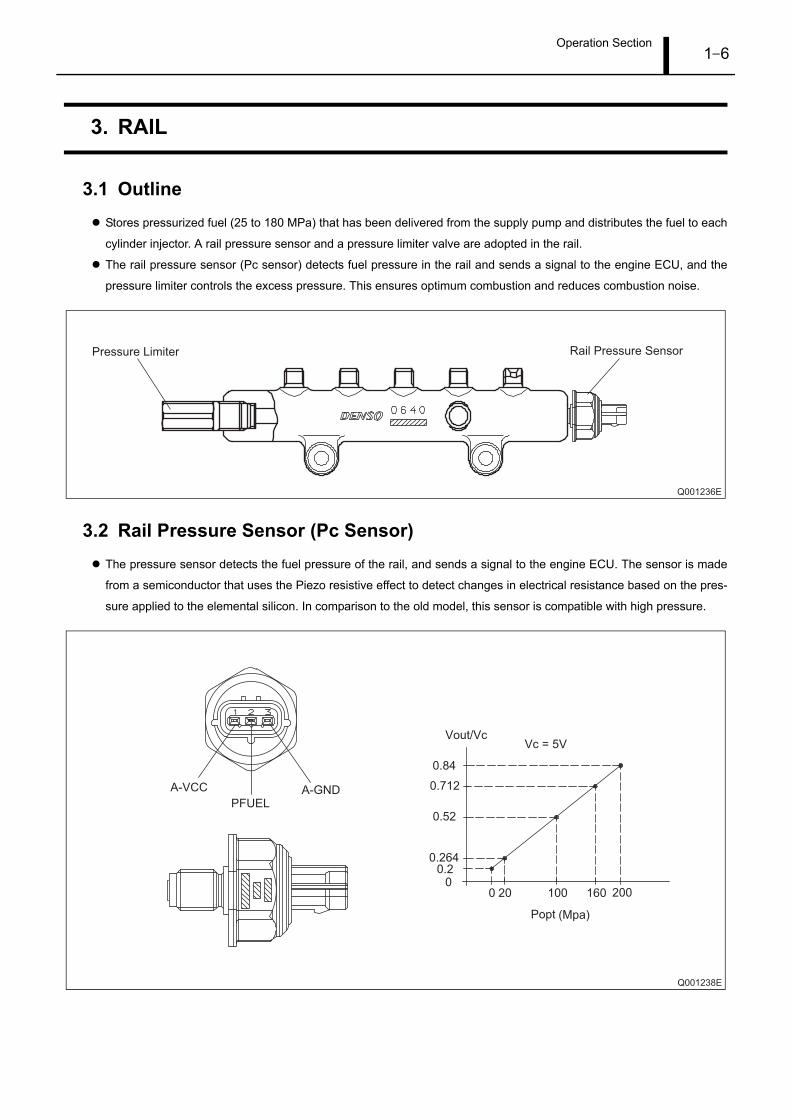
3.1 OutlineStores pressurized fuel (25 to 180 MPa) that has been delivered from the supply pump and distributes the fuel to each
cylinder injector. A rail pressure sensor and a pressure limiter valve are adopted in the rail.
The rail pressure sensor (Pc sensor) detects fuel pressure in the rail and sends a signal to the engine ECU, and the
pressure limiter controls the excess pressure. This ensures optimum combustion and reduces combustion noise.
3.2 Rail Pressure Sensor (Pc Sensor)The pressure sensor detects the fuel pressure of the rail, and sends a signal to the engine ECU. The sensor is made
from a semiconductor that uses the Piezo resistive effect to detect changes in electrical resistance based on the pres-
sure applied to the elemental silicon. In comparison to the old model, this sensor is compatible with high pressure.
Q001236E
Rail Pressure SensorPressure Limiter
Q001238E
Vout/Vc
A-VCC A-GNDPFUEL
Vc = 5V
(Mpa)Popt
2001601002000
0.20.264
0.712
0.84
0.52

Operation Section1–7
3.3 Pressure limiterThe pressure limiter releases pressure when the internal pressure of the rail becomes abnormally high. The pressure
limiter opens when internal pressure reaches 221MPa (2254 kg/cm2) and closes when rail pressure reaches a given
set pressure. Fuel released from the pressure limiter is returned to the fuel tank.
Q001239E
Valve Open
Valve Close50 MPa (509.5 kg/cm2)
221 MPa (2254 kg/cm2)
From rail
To fuel tank
Operation Section1–8
4. INJECTOR (G2 TYPE)
4.1 OutlineThe injectors inject the high-pressure fuel from the rail into the combustion chambers at the optimum injection timing,
rate, and spray condition, in accordance with commands received from the ECU.
For information on both basic injector operation and handling injectors with QR codes, refer to the publication entitled,
"General Edition Manual: Common Rail System (Doc ID: 00400076E)."
4.2 CharacteristicsA compact, energy-saving solenoid-control type TWV (Two-Way Valve) injector has been adopted.
QR codes displaying various injector characteristics and the ID codes showing these in numeric form (30 alphanumeric
figures) are engraved on the injector head. The common rail system optimizes injection volume control using this infor-
mation. When an injector is newly installed in a vehicle, it is necessary to enter the ID codes in the engine ECU using
the MITSUBISHI diagnosis tool (MUT III).
Operation Section1–9
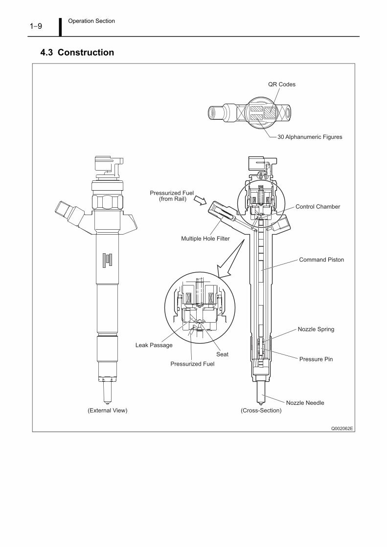
4.3 Construction
Q002062E
QR Codes
30 Alphanumeric Figures
Pressurized Fuel (from Rail)
Seat
Leak Passage
Multiple Hole Filter
Pressurized Fuel
Command Piston
Nozzle Spring
Pressure Pin
Nozzle Needle
Control Chamber
(External View) (Cross-Section)

Operation Section1–10
4.4 QR CodesConventionally the whole injector Assy was replaced during injector replacement, but QR (Quick Response) codes have
been adopted to improve injector quantity precision.
QR codes have resulted in a substantial increase in the number of fuel injection quantity correction points, greatly im-
proving precision. The characteristics of the engine cylinders have been further unified, contributing to improvements
in combustion efficiency, reductions in exhaust gas emissions and so on.
Q001242E
ID Codes (30 base 16 characters)Base 16 characters noting fuel injection quantity correction information for market service use
QR Codes ( 9.9mm)
Q002063E
Inje
ctio
n Q
ua
ntity
Q
180 Mpa
80 Mpa
112 Mpa
135 Mpa
48 Mpa
25 Mpa
Actuating Pluse Width TQ
<4M41 Engine Model>
Correction
8 Points

Operation Section1–11
5. OPERATION OF CONTROL SYSTEM COMPONENTS
5.1 Engine Control System Diagram
Q002064E
Rail
Rail Pressure Sensor(Pc Sensor)
Pressure limiter
Injector
Engine ECU
SCV
(Sucton Control Valve)
Glow Relay
CrankshaftPosition Sensor(NE Sensor)
Cylinder Recognition
Position Sensor
(TDC Sensor)
Turbo PressureSensor
Electronic ControlThrottle
FuelTank
Accelerator Position Sensor
Ignition Switch Signal
Starter Signal
Vehicle Speed Signal
Mitsubishi Diagnosis Tool (MUT-III)
Battery Voltage
Other Signals
Mass Airflow Meter
(With Intake Air Temperature)
Fuel Temperature
Sensor
CoolantTemperatureSensorDifferential
Pressure Sensor
Exhaust GasTemperature
Sensor 3
Exhaust GasTemperature
Sensor 1
Exhaust GasTemperature
Sensor 2
Diesel OxidationCatalyst (DOC)
DOC
DOC
Diesel ParticulateFilter (DPF)
Variable GeometryTurbo (VGT)
Automatic TransmissionVehicles
Manual TransmissionVehicles
Automatic TransmissionVehicles
Temperature Sensor for Differential PressureSensor LearningAbsolute Pressure Sensor(Upstream Pressure)
Operation Section1–12
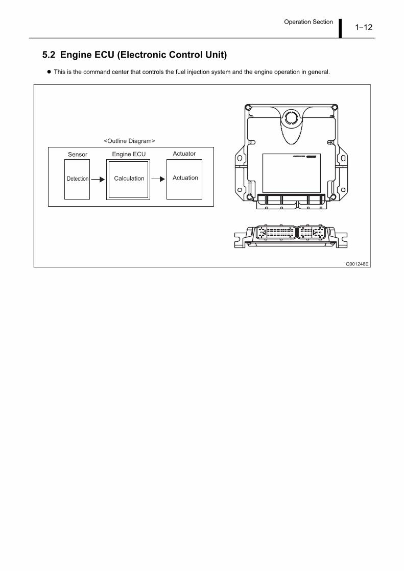
5.2 Engine ECU (Electronic Control Unit)This is the command center that controls the fuel injection system and the engine operation in general.
Q001248E
<Outline Diagram>
Engine ECU
Detection Calculation Actuation
Sensor Actuator

Operation Section1–13
(1) External wiring diagram
Q002335E
Variable GeometryTurbo (VGT)
Solenoid
Fan Relay
A/C Relay
Swirl Control Valve
ElectronicControlThrottle
DC Motor
ElectronicControlThrottle
Position Sensor
Glow PlugRelay
Accelerator PositionSensor(Main)
AcceleratorPositionSensor(Sub)
Automatic Transmission Vehicles Only
Automatic Transmission Vehicles Only
Automatic Transmission Vehicles Only
Manual Transmission Vehicles Only
Manual Transmission Vehicles Only
ECCS Relay
P1 P2
IG
EGRDC Motor
EGR PositionSensor
Sta
rte
r M
oto
r
OFFS
KEYIG
ACC IG
IG
3rd/4th SW
FWD/BK SW
BATT
Ba
tte
ry
Body Earth
Crankshaft PositionSensor
Exhaust GasTemperature Sensor 1
CylinderRecognition
Sensor
Power Steering SW
PTC Heater Relay
1st Shift SW
Reverse Shift SW
DPF DifferentialPressure Sensor
DPF AbsolutePressure Sensor
Temperature Sensor for Differential Pressure
Sensor Learning
A/C2 SW
Body Earth
IG
IG
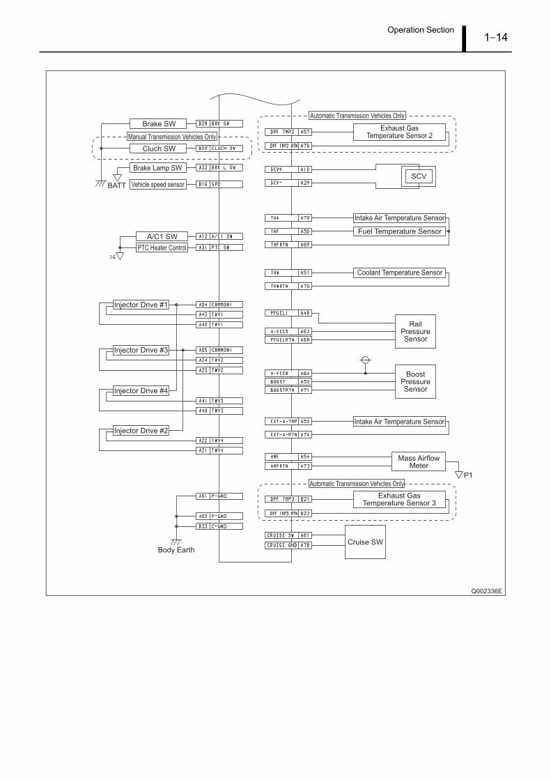
Operation Section1–14
Q002336E
Brake Lamp SW
Vehicle speed sensor
PTC Heater Control
Injector Drive #1
Injector Drive #3
Injector Drive #4
Injector Drive #2
Exhaust GasTemperature Sensor 2
Intake Air Temperature Sensor
Fuel Temperature Sensor
Coolant Temperature Sensor
BoostPressureSensor
Intake Air Temperature Sensor
Mass AirflowMeter
Exhaust GasTemperature Sensor 3
Automatic Transmission Vehicles Only
Manual Transmission Vehicles Only
Automatic Transmission Vehicles Only
A/C1 SW
Body Earth
SCV
RailPressureSensor
P1
Cruise SW
Brake SW
Cluch SW
BATT
Operation Section1–15
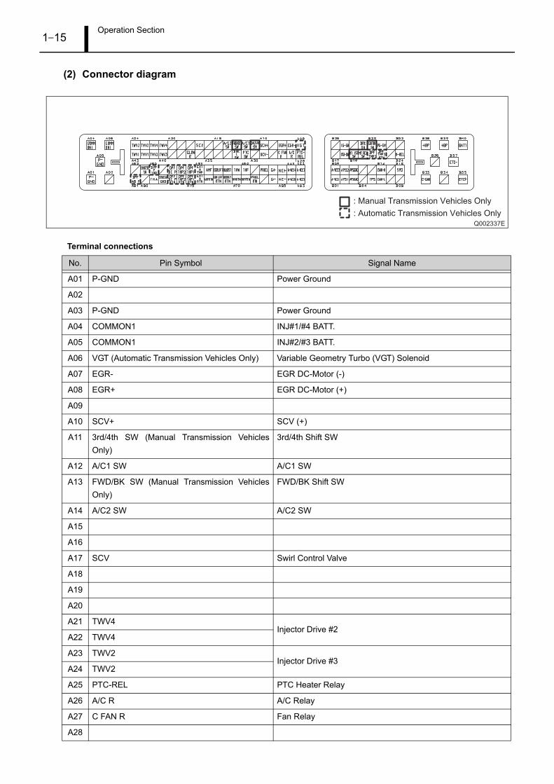
(2) Connector diagram
Terminal connections
No. Pin Symbol Signal Name
A01 P-GND Power Ground
A02
A03 P-GND Power Ground
A04 COMMON1 INJ#1/#4 BATT.
A05 COMMON1 INJ#2/#3 BATT.
A06 VGT (Automatic Transmission Vehicles Only) Variable Geometry Turbo (VGT) Solenoid
A07 EGR- EGR DC-Motor (-)
A08 EGR+ EGR DC-Motor (+)
A09
A10 SCV+ SCV (+)
A11 3rd/4th SW (Manual Transmission VehiclesOnly)
3rd/4th Shift SW
A12 A/C1 SW A/C1 SW
A13 FWD/BK SW (Manual Transmission VehiclesOnly)
FWD/BK Shift SW
A14 A/C2 SW A/C2 SW
A15
A16
A17 SCV Swirl Control Valve
A18
A19
A20
A21 TWV4Injector Drive #2
A22 TWV4
A23 TWV2Injector Drive #3
A24 TWV2
A25 PTC-REL PTC Heater Relay
A26 A/C R A/C Relay
A27 C FAN R Fan Relay
A28
Q002337E
: Automatic Transmission Vehicles Only
: Manual Transmission Vehicles Only
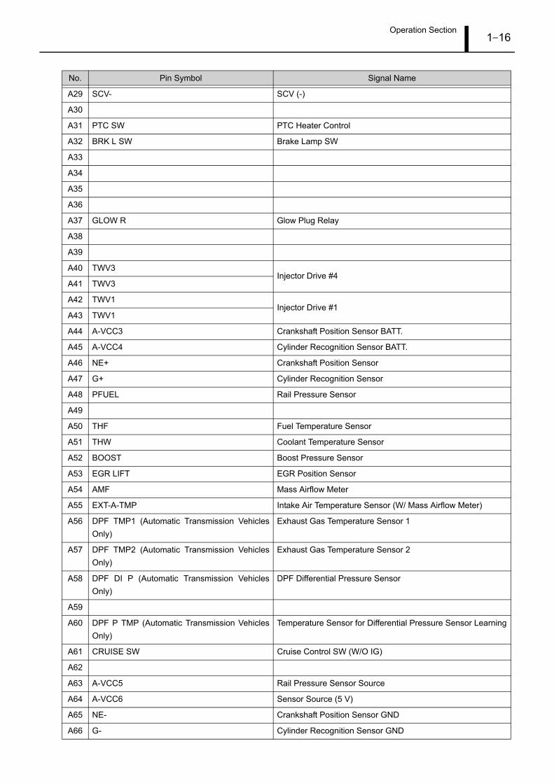
Operation Section1–16
A29 SCV- SCV (-)
A30
A31 PTC SW PTC Heater Control
A32 BRK L SW Brake Lamp SW
A33
A34
A35
A36
A37 GLOW R Glow Plug Relay
A38
A39
A40 TWV3Injector Drive #4
A41 TWV3
A42 TWV1Injector Drive #1
A43 TWV1
A44 A-VCC3 Crankshaft Position Sensor BATT.
A45 A-VCC4 Cylinder Recognition Sensor BATT.
A46 NE+ Crankshaft Position Sensor
A47 G+ Cylinder Recognition Sensor
A48 PFUEL Rail Pressure Sensor
A49
A50 THF Fuel Temperature Sensor
A51 THW Coolant Temperature Sensor
A52 BOOST Boost Pressure Sensor
A53 EGR LIFT EGR Position Sensor
A54 AMF Mass Airflow Meter
A55 EXT-A-TMP Intake Air Temperature Sensor (W/ Mass Airflow Meter)
A56 DPF TMP1 (Automatic Transmission VehiclesOnly)
Exhaust Gas Temperature Sensor 1
A57 DPF TMP2 (Automatic Transmission VehiclesOnly)
Exhaust Gas Temperature Sensor 2
A58 DPF DI P (Automatic Transmission VehiclesOnly)
DPF Differential Pressure Sensor
A59
A60 DPF P TMP (Automatic Transmission VehiclesOnly)
Temperature Sensor for Differential Pressure Sensor Learning
A61 CRUISE SW Cruise Control SW (W/O IG)
A62
A63 A-VCC5 Rail Pressure Sensor Source
A64 A-VCC6 Sensor Source (5 V)
A65 NE- Crankshaft Position Sensor GND
A66 G- Cylinder Recognition Sensor GND
No. Pin Symbol Signal Name

Operation Section1–17
A67
A68 PFUELRTN Rail Pressure Sensor Earth
A69 THFRTN Sensor Earth (Intake Air Temperature Sensor, Fuel Tempera-ture Sensor)
A70 THWRTN Coolant Temperature Sensor Earth
A71 BOOSTRTN Boost Pressure Sensor Earth
A72 EGR LIFT RTN Sensor Earth (EGR Position Sensor, Throttle Position Sensor)
A73 AMFRTN Mass Airflow Meter Earth
A74 EXT-A-RTN Intake Air Temperature Sensor Earth (W/ Mass Airflow Meter)
A75 DPF TMP1 RTN (Automatic Transmission Vehi-cles Only)
Exhaust Gas Temperature Sensor 1 Return
A76 DPF TMP2 RTN (Automatic Transmission Vehi-cles Only)
Exhaust Gas Temperature Sensor 2 Return
A77 DPF DI P RTN (Automatic Transmission Vehi-cles Only)
DPF differential pressure sensor Return
A78 CRUISE GND Cruise Control SW GND
A79 THA Intake Air Temperature Sensor
A80
A81 DPF AB P (Automatic Transmission VehiclesOnly)
DPF Absolute Pressure Sensor
B01 A-VCC1 Accelerator Position Sensor (Main) Source
B02 APS1 Accelerator Position Sensor (Main)
B03 APS1GND Accelerator Position Sensor (Main) Earth
B04
B05 TPS Electronic Control Throttle Position Sensor
B06 CAN1-L CAN Lo (W/O Resistor)
B07
B08
B09 A-VCC2 Accelerator Position Sensor (Sub) Source
B10 APS2 Accelerator Position Sensor (Sub)
B11 APS2GND Accelerator Position Sensor (Sub) Earth
B12
B13
B14 CAN1-H CAN Hi (W/O Resistor)
B15
B16 SPD Vehicle speed sensor
B17
B18 STA-SW Start Signal
B19 MT 1st SW (Manual Transmission VehiclesOnly)
1st Shift SW
B20 MT REV SW (Manual Transmission VehiclesOnly)
Reverse Shift SW
No. Pin Symbol Signal Name
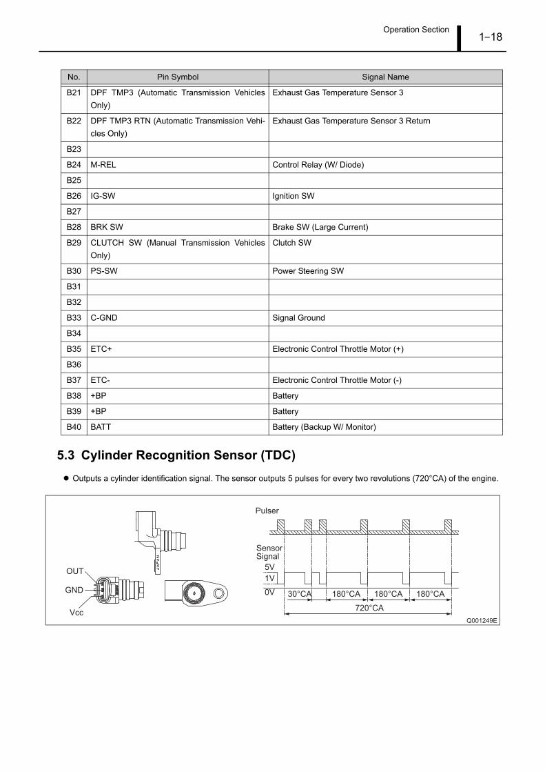
Operation Section1–18
5.3 Cylinder Recognition Sensor (TDC)Outputs a cylinder identification signal. The sensor outputs 5 pulses for every two revolutions (720°CA) of the engine.
B21 DPF TMP3 (Automatic Transmission VehiclesOnly)
Exhaust Gas Temperature Sensor 3
B22 DPF TMP3 RTN (Automatic Transmission Vehi-cles Only)
Exhaust Gas Temperature Sensor 3 Return
B23
B24 M-REL Control Relay (W/ Diode)
B25
B26 IG-SW Ignition SW
B27
B28 BRK SW Brake SW (Large Current)
B29 CLUTCH SW (Manual Transmission VehiclesOnly)
Clutch SW
B30 PS-SW Power Steering SW
B31
B32
B33 C-GND Signal Ground
B34
B35 ETC+ Electronic Control Throttle Motor (+)
B36
B37 ETC- Electronic Control Throttle Motor (-)
B38 +BP Battery
B39 +BP Battery
B40 BATT Battery (Backup W/ Monitor)
No. Pin Symbol Signal Name
Q001249E
30°CA 180°CA 180°CA
720°CA
180°CA
5V
1V
0V
Pulser
SensorSignal
Vcc
GND
OUT
Operation Section1–19
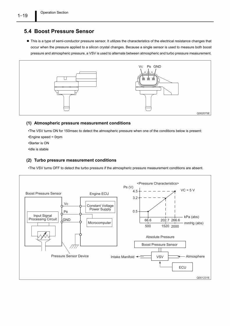
5.4 Boost Pressure SensorThis is a type of semi-conductor pressure sensor. It utilizes the characteristics of the electrical resistance changes that
occur when the pressure applied to a silicon crystal changes. Because a single sensor is used to measure both boost
pressure and atmospheric pressure, a VSV is used to alternate between atmospheric and turbo pressure measurement.
(1) Atmospheric pressure measurement conditions
•The VSV turns ON for 150msec to detect the atmospheric pressure when one of the conditions below is present:
•Engine speed = 0rpm
•Starter is ON
•Idle is stable
(2) Turbo pressure measurement conditions
•The VSV turns OFF to detect the turbo pressure if the atmospheric pressure measurement conditions are absent.
Q002075E
GNDPBVC
Q001231E
VSV Atmosphere
Boost Pressure Sensor
Intake Manifold
0.5
4.5
3.2
VC = 5 V
266.6
Absolute Pressure
66.6 202.7
500 20001520
PB (V)
kPa (abs)
mmHg (abs)
<Pressure Characteristics>
ECU
Boost Pressure Sensor
Pressure Sensor Device
Engine ECU
Constant VoltagePower Supply
Microcomputer
Input SignalProcessing Circuit
Vc
PB
GND
Operation Section1–20
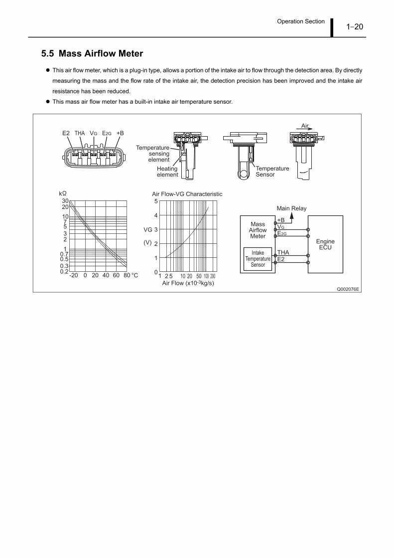
5.5 Mass Airflow MeterThis air flow meter, which is a plug-in type, allows a portion of the intake air to flow through the detection area. By directly
measuring the mass and the flow rate of the intake air, the detection precision has been improved and the intake air
resistance has been reduced.
This mass air flow meter has a built-in intake air temperature sensor.
Q002076E
Temperaturesensingelement
E2 THA VG E2G +B
Heatingelement
Air
Air Flow-VG Characteristic
5
4
3
2
1
0
VG
(V)
1 2 5 10 20 50 100 200Air Flow (x10-3kg/s)
-200.20.30.50.7
1
23
5710
2030
k
20 40 60 80 °C0
TemperatureSensor
MassAirflowMeter
IntakeTemperature
Sensor
EngineECU
VG
E2G
+B
THAE2
Main Relay
Operation Section1–21
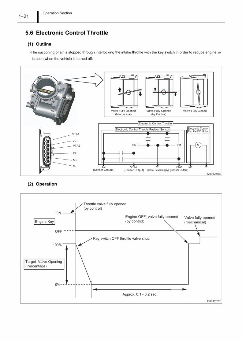
5.6 Electronic Control Throttle
(1) Outline
•The suctioning of air is stopped through interlocking the intake throttle with the key switch in order to reduce engine vi-
bration when the vehicle is turned off.
(2) Operation
Q001256E
VTA1
VTA1(Sensor Output)
M+ M-
IC1
VC
VC(Sensor Power Supply)
VTA2
VTA2(Sensor Output)
E2
E2(Sensor Ground)
M+
M-
IC2 M
Valve Fully Opened
(Mechanical)
Valve Fully Opened
(by Control)
Valve Fully Closed
Electronic Control Throttle Position Sensor
Electronic Control Throttle
Electronic ControlThrottle DC Motor
Q001232E
ON
Target Valve Opening
(Percentage)
Throttle valve fully opened
(by control)
Key switch OFF throttle valve shut.
Approx. 0.1 - 0.2 sec.
Engine OFF, valve fully opened
(by control) Valve fully opened
(mechanical)
OFF
100%
Engine Key
0%

Operation Section1–22
6. FUEL INJECTION CONTROL
6.1 OutlineThe following explains the types of control used in the PAJERO system. For details on each type of control, refer to the
publication entitled, "General Edition Manual: Common Rail System (Doc ID: 00400076E)."
(1) Fuel injection rate control function
•Pilot injection control injects a small amount of fuel before the main injection.
(2) Fuel injection quantity control function
•The fuel injection quantity control function replaces the conventional governor function. It controls the fuel injection to an
optimal injection quantity based on the engine speed and accelerator position signals.
(3) Fuel injection timing control function
•The fuel injection timing control function replaces the conventional timer function. It controls the injection to an optimal
timing based on the engine speed and the injection quantity.
(4) Fuel injection pressure control function (rail pressure control function)
•The fuel injection pressure control function (rail pressure control function) controls the discharge volume of the pump by
measuring the fuel pressure at the rail pressure sensor and feeding it back to the ECU. It effects pressure feedback
control so that the discharge volume matches the optimal (command) value set in accordance with the engine speed
and the injection quantity.
6.2 Fuel Injection Quantity ControlThe following explains controls unique to the PAJERO. For other types of basic fuel injection quantity control, refer to
the publication entitled, "General Edition Manual: Common Rail System (Doc ID: 00400076E)."
(1) Maximum injection quantity
•The basic maximum injection quantity is determined by the engine speed, the added corrections for intake air pressure,
and gear position.
QB0717E
Engine Speed
Ba
sic
Ma
xim
um
In
jectio
n Q
ua
ntity
Operation Section1–23
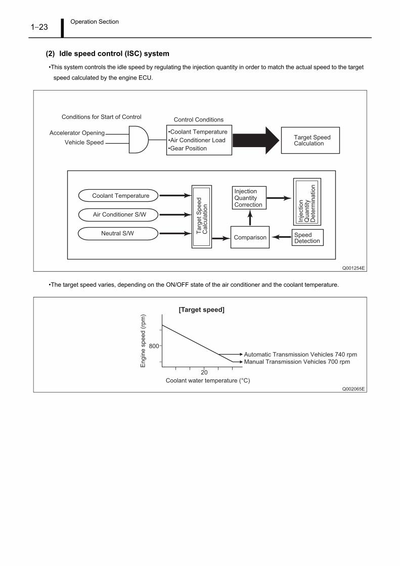
(2) Idle speed control (ISC) system
•This system controls the idle speed by regulating the injection quantity in order to match the actual speed to the target
speed calculated by the engine ECU.
•The target speed varies, depending on the ON/OFF state of the air conditioner and the coolant temperature.
Q001254E
•Coolant Temperature
•Air Conditioner Load
•Gear Position
Accelerator Opening
Vehicle Speed
Conditions for Start of Control Control Conditions
Target Speed Calculation
Comparison
InjectionQuantityCorrection
SpeedDetection
Air Conditioner S/W
Coolant Temperature
Neutral S/W Ta
rge
t S
pe
ed
C
alc
ula
tio
n
Inje
ctio
nQ
ua
ntity
De
term
ina
tio
n
Q002065E
[Target speed]
800
20
Coolant water temperature (°C)
En
gin
e s
pe
ed
(rp
m)
Manual Transmission Vehicles 700 rpm
Automatic Transmission Vehicles 740 rpm

Operation Section1–24
6.3 Other ControlsThe following explains microinjection quantity learning control.
(1) Microinjection quantity learning control
Outline•Quantity learning control is used in every vehicle engine (injector) to preserve the accuracy of quantity (specifically, pilot
injection quantity.)
This type of control is first performed when shipped from the factory (L/O), and later is automatically performed every
time the vehicle runs a set distance (for details, see item "A".) Because of quantity learning control, the accuracy of each
injector can be preserved not only initially, but also as deterioration in injection occurs over time. As a result of this learn-
ing, correction values are recorded in the ECU. During normal driving operations, this correction value is used to make
modifications to injection commands, resulting in accurate microinjection.
Learning operations•For every two no load, idle instability conditions established (See chart "A" below) quantity learning takes place.
In addition, it is also possible to perform quantity learning control manually as a diagnostic tool.
Q001250E
Manual Learning Operations (as a Diagnostic Tool)
(A)
Number of IG OFF Occurrences
Vehicle Running Distance
Injection Quantity Deterioration Over Time Judgment
No Load Idle Instability Condition
Establishment of
Learning Operations
Operation Section1–25
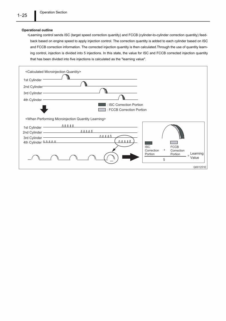
Operational outline•Learning control sends ISC (target speed correction quantity) and FCCB (cylinder-to-cylinder correction quantity) feed-
back based on engine speed to apply injection control. The correction quantity is added to each cylinder based on ISC
and FCCB correction information. The corrected injection quantity is then calculated.Through the use of quantity learn-
ing control, injection is divided into 5 injections. In this state, the value for ISC and FCCB corrected injection quantity
that has been divided into five injections is calculated as the "learning value".
Q001251E
1st Cylinder
2nd Cylinder
3rd Cylinder
4th Cylinder
1st Cylinder
2nd Cylinder
3rd Cylinder
4th Cylinder
: ISC Correction Portion
ISC
Correction
Portion
: FCCB Correction Portion
FCCB
Correction
Portion
<Calculated Microinjection Quantity>
<When Performing Microinjection Quantity Learning>
Learning
Value
Operation Section1–26
7. OTHER SYSTEMS
7.1 OutlineThe following explains the Diesel Particulate Filter (DPF) System installed in PAJEROs equipped with an automatic
transmission.
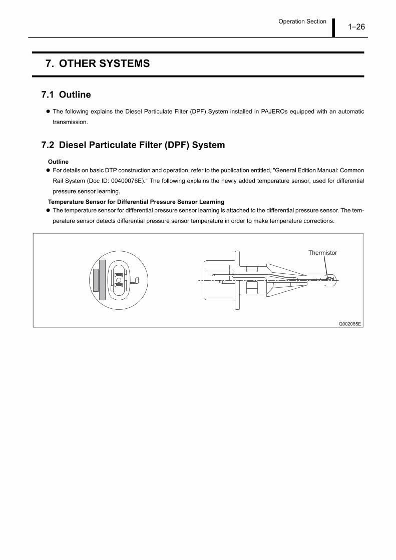
7.2 Diesel Particulate Filter (DPF) SystemOutline
For details on basic DTP construction and operation, refer to the publication entitled, "General Edition Manual: Common
Rail System (Doc ID: 00400076E)." The following explains the newly added temperature sensor, used for differential
pressure sensor learning.
Temperature Sensor for Differential Pressure Sensor LearningThe temperature sensor for differential pressure sensor learning is attached to the differential pressure sensor. The tem-
perature sensor detects differential pressure sensor temperature in order to make temperature corrections.
Q002085E
Thermistor
Operation Section1–27
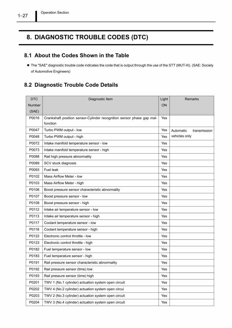
8. DIAGNOSTIC TROUBLE CODES (DTC)
8.1 About the Codes Shown in the TableThe "SAE" diagnostic trouble code indicates the code that is output through the use of the STT (MUT-III). (SAE: Society
of Automotive Engineers)
8.2 Diagnostic Trouble Code Details
DTC
Number
(SAE)
Diagnostic Item Light
ON
Remarks
P0016 Crankshaft position sensor-Cylinder recognition sensor phase gap mal-function
Yes
P0047 Turbo PWM output - low Yes Automatic transmissionvehicles onlyP0048 Turbo PWM output - high Yes
P0072 Intake manifold temperature sensor - low Yes
P0073 Intake manifold temperature sensor - high Yes
P0088 Rail high pressure abnormality Yes
P0089 SCV stuck diagnosis Yes
P0093 Fuel leak Yes
P0102 Mass Airflow Meter - low Yes
P0103 Mass Airflow Meter - high Yes
P0106 Boost pressure sensor characteristic abnormality Yes
P0107 Boost pressure sensor - low Yes
P0108 Boost pressure sensor - high Yes
P0112 Intake air temperature sensor - low Yes
P0113 Intake air temperature sensor - high Yes
P0117 Coolant temperature sensor - low Yes
P0118 Coolant temperature sensor - high Yes
P0122 Electronic control throttle - low Yes
P0123 Electronic control throttle - high Yes
P0182 Fuel temperature sensor - low Yes
P0183 Fuel temperature sensor - high Yes
P0191 Rail pressure sensor characteristic abnormality Yes
P0192 Rail pressure sensor (time) low Yes
P0193 Rail pressure sensor (time) high Yes
P0201 TWV 1 (No.1 cylinder) actuation system open circuit Yes
P0202 TWV 4 (No.2 cylinder) actuation system open circui Yes
P0203 TWV 2 (No.3 cylinder) actuation system open circuit Yes
P0204 TWV 3 (No.4 cylinder) actuation system open circuit Yes
Operation Section1–28
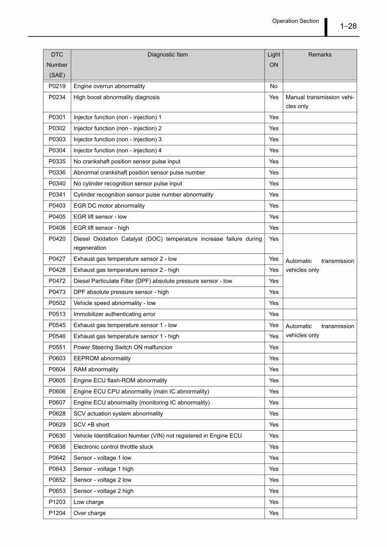
P0219 Engine overrun abnormality No
P0234 High boost abnormality diagnosis Yes Manual transmission vehi-cles only
P0301 Injector function (non - injection) 1 Yes
P0302 Injector function (non - injection) 2 Yes
P0303 Injector function (non - injection) 3 Yes
P0304 Injector function (non - injection) 4 Yes
P0335 No crankshaft position sensor pulse input Yes
P0336 Abnormal crankshaft position sensor pulse number Yes
P0340 No cylinder recognition sensor pulse input Yes
P0341 Cylinder recognition sensor pulse number abnormality Yes
P0403 EGR DC motor abnormality Yes
P0405 EGR lift sensor - low Yes
P0406 EGR lift sensor - high Yes
P0420 Diesel Oxidation Catalyst (DOC) temperature increase failure duringregeneration
Yes
Automatic transmissionvehicles only
P0427 Exhaust gas temperature sensor 2 - low Yes
P0428 Exhaust gas temperature sensor 2 - high Yes
P0472 Diesel Particulate Filter (DPF) absolute pressure sensor - low Yes
P0473 DPF absolute pressure sensor - high Yes
P0502 Vehicle speed abnormality - low Yes
P0513 Immobilizer authenticating error Yes
P0545 Exhaust gas temperature sensor 1 - low Yes Automatic transmissionvehicles onlyP0546 Exhaust gas temperature sensor 1 - high Yes
P0551 Power Steering Switch ON malfuncion Yes
P0603 EEPROM abnormality Yes
P0604 RAM abnormality Yes
P0605 Engine ECU flash-ROM abnormality Yes
P0606 Engine ECU CPU abnormality (main IC abnormality) Yes
P0607 Engine ECU abnormality (monitoring IC abnormality) Yes
P0628 SCV actuation system abnormality Yes
P0629 SCV +B short Yes
P0630 Vehicle Identification Number (VIN) not registered in Engine ECU Yes
P0638 Electronic control throttle stuck Yes
P0642 Sensor - voltage 1 low Yes
P0643 Sensor - voltage 1 high Yes
P0652 Sensor - voltage 2 low Yes
P0653 Sensor - voltage 2 high Yes
P1203 Low charge Yes
P1204 Over charge Yes
DTC
Number
(SAE)
Diagnostic Item Light
ON
Remarks

Operation Section1–29
P1272 Pressure limiter open valve abnormality Yes
P1273 Supply pump single-side element abnormality Yes
P1274 Supply pump protective fail flag Yes
P1275 Supply pump replace fail flag Yes
P1298 Turbo system (positive deviation) Yes
Automatic transmissionvehicles only
P1299 Turbo system (negative deviation) Yes
P1427 Exhaust gas temperature sensor 3 - low Yes
P1428 Exhaust gas temperature sensor 3 - high Yes
P1474 Differential pressure sensor temperature sensor low Yes
P1475 Differential pressure sensor temperature sensor high Yes
P1497 DOC regeneration time exceeded Yes
P1498 Regeneration timing abnormality Yes
P1499 DPF heat loss temperature abnormality Yes
P1564 Cruise control switch abnormality No
P1571 Brake switch abnormality No
P1625 QR data abnormality Yes
P1626 QR data failure to write abnormality Yes
P2009 Swirl control (VSS) output (VSV) open load/short to GND Yes
P2010 Swirl control (VSS) output (VSV) short to BATT Yes
P2118 Electronic control throttle DC motor over current abnormality Yes
P2122 Accelerator position sensor-1 low Yes
P2123 Accelerator position sensor-1 high final Yes
P2124 Accelerator position sensor-1 high No
P2127 Accelerator position sensor-2 low Yes
P2128 Accelerator position sensor-2 high final Yes
P2138 Accelerator positon sensor - duplicate malfunction high Yes
Accelerator position sensor - duplicate malfunction low Yes
Accelerator position sensor characteristic abnormality Yes
P2146 Common 1 system open circuit Yes
P2147 COM1 TWV actuation system ground short Yes
P2148 COM1 TWV actuation system +B short Yes
P2149 Common 2 system open circuit Yes
P2228 Atmospheric pressure sensor - low Yes
P2229 Atmospheric pressure sensor - high Yes
P2413 EGR feedback abnormality Yes
P2454 Differential pressure sensor low Yes Automatic transmissionvehicles onlyP2455 Differential pressure sensor high Yes
P252F Oil level abnormality No
UD073 CAN bus OFF error No
DTC
Number
(SAE)
Diagnostic Item Light
ON
Remarks
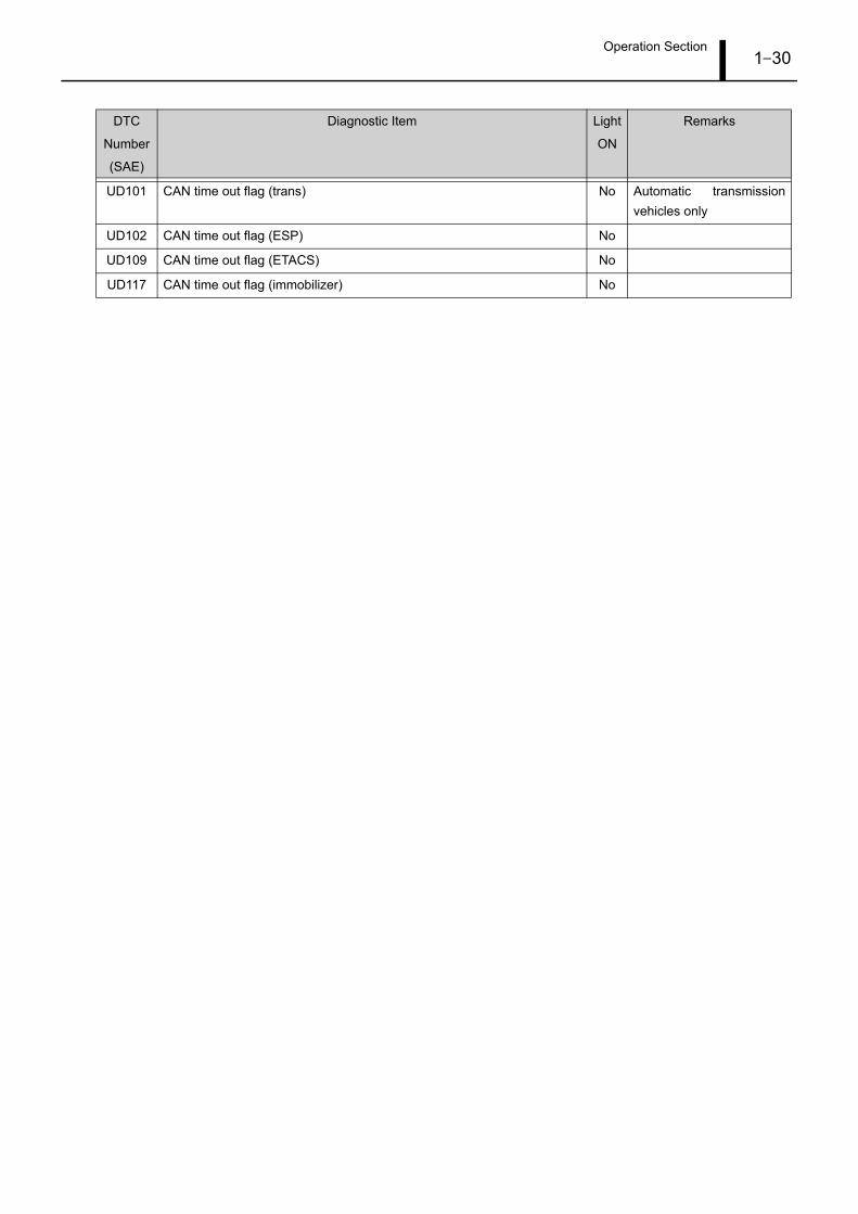
Operation Section1–30
UD101 CAN time out flag (trans) No Automatic transmissionvehicles only
UD102 CAN time out flag (ESP) No
UD109 CAN time out flag (ETACS) No
UD117 CAN time out flag (immobilizer) No
DTC
Number
(SAE)
Diagnostic Item Light
ON
Remarks

Operation Section1–31
DENSO CORPORATION Service Department
Edited and published by:
1-1 Showa-cho, Kariya, Aichi Prefecture, Japan
Published : March 2007


