VHU INSULATED HUMIDIFIED CABINETS VHU7 VHU18 - NOTICE - This Manual is prepared for the use of trained Vulcan Service Technicians and should not be used by those not properly qualified. This manual is not intended to be all encompassing. If you have not attended a Vulcan Service School for this product, you should read, in its entirety, the repair procedure you wish to perform to determine if you have the necessary tools, instruments and skills required to perform the procedure. Procedures for which you do not have the necessary tools, instruments and skills should be performed by a trained Vulcan Service Technician. The reproduction, transfer, sale or other use of this Manual, without the express written consent of Vulcan, is prohibited. This manual has been provided to you by ITW Food Equipment Group LLC ("ITW FEG") without charge and remains the property of ITW FEG, and by accepting this manual you agree that you will return it to ITW FEG promptly upon its request for such return at any time in the future. SERVICE MANUAL A product of Vulcan-Hart 3600 North Point Blvd Baltimore, MD 21222 F45642 (0217)
Transcript
VHU INSULATED HUMIDIFIEDCABINETSVHU7VHU18
- NOTICE -This Manual is prepared for the use of trained Vulcan ServiceTechnicians and should not be used by those not properlyqualified.
This manual is not intended to be all encompassing. If you havenot attended a Vulcan Service School for this product, you shouldread, in its entirety, the repair procedure you wish to perform todetermine if you have the necessary tools, instruments and skillsrequired to perform the procedure. Procedures for which you donot have the necessary tools, instruments and skills should beperformed by a trained Vulcan Service Technician.
The reproduction, transfer, sale or other use of this Manual,without the express written consent of Vulcan, is prohibited.
This manual has been provided to you by ITW Food EquipmentGroup LLC ("ITW FEG") without charge and remains the propertyof ITW FEG, and by accepting this manual you agree that you willreturn it to ITW FEG promptly upon its request for such return atany time in the future.
SERVICE MANUAL
A product of Vulcan-Hart 3600 North Point Blvd Baltimore, MD 21222F45642 (0217)
This manual is applicable only to models listed on thecover page. Procedures in this manual will apply to allmodels unless specified. Pictures and illustrations canbe of any model unless they need to be model specific.
INSTALLATION, OPERATION ANDCLEANING
For detailed installation, operation and cleaninginstructions, refer to the Installation & OperationManual sent with each unit. The manual is alsoavailable online at www.vulcanequipment.com.
TOOLS
Standard
1. Standard set of hand tools.
2. VOM with minimum of NFPA-70E CATIII 600V,UL/CSA/TUV listed. Sensitivity of at least 20,000ohms per volt. Meter leads must also be rated atCAT III 600V.
3. Clamp on type amp meter with minimum ofNFPA-70E CAT III 600V,UL/CSA/TUV listed.
4. Temperature tester (thermocouple type).
5. ESD (Electrostatic discharge) Protection Kit.
Special• Handheld, digital temperature and humidity
sensor Grainger No. 3LYH7 or equivalent.
SPECIFICATIONS
ElectricalModel Volts Wattage AmperageVHU7
VHU18120 1,500 12.5
VHU7
VHU18120 2,000
(Optional) 16.7
Heating ElementsModel Wattage Voltage ResistanceVHU7
VHU181500
(Standard) 120 8.80-10.27
Heating ElementsModel Wattage Voltage ResistanceVHU7
VHU182000
(Optional) 120 6.57-7.66
Pan Capacity
ModelCapacity *
12" X 20" X 2 ½" 18" X 26"SHEET PANS
VHU7 14 7
VHU18 36 18
(*) Capacity based on 3" spacing between pans.
VHU INSULATED HUMIDIFIED CABINETS - GENERAL
Page 3 of 16 F45642 (0217)
SERVICE PROCEDURES AND ADJUSTMENTS
TEMPERATURE AND HUMIDITYCALIBRATION
The oven and its parts are hot. Usecare when operating, cleaning or servicing the oven.
1. Check room temperature.
2. Place temperature and humidity probe at thecenter of the cabinet.
3. Set unit temperature to 145°F.
4. Set relative humidity to 65%RH.
5. Wait 45 minutes.
6. The temperature setting should be between 138- 152F° and relative humidity between 45%RH -85%RH.
VERIFY• When using cabinet, frequently opening the
door will affect average internaltemperature. Modify set temperature asnecessary to ensure product is held aboveappropriate food safe temperature.
RESET SENSOR CODES
The oven and its parts are hot. Usecare when operating, cleaning or servicing the oven.
1. Reset unit (turn it off, then on).
2. Turn unit off and remove sensor cover.
NOTE: Sensor board is located inside cabinet at thetop of the cavity toward the front.
Fig. 1
3. Dry off sensor and wires.
Fig. 2
4. Disconnect sensor wire harness plugs and dryout any moisture in connectors.
5. Plug sensor wire connectors into board.
6. Turn unit on to verify error code has cleared.
7. If error codes are not clear, replace bothSENSOR BOARD AND WIRE HARNESS.
8. Install sensor board cover.
9. Verify operation.
HEATER ELEMENT TEST
Certain procedures inthis section require electrical test ormeasurements while power is appliedto the machine. Exercise extremecaution at all times and follow Arc Flashprocedures. If test points are not easilyaccessible, disconnect power andfollow Lockout/Tagout procedures,attach test equipment and reapplypower to test.
1. Access the heater element being tested.
• HUMIDITY ELEMENT (BELOW PAN)
• AIR ELEMENT
2. Check resistance using HEATING ELEMENTtable.
Heating ElementsModel Wattage Voltage ResistanceVHU7
VHU181500
(Standard) 120 8.80-10.27
VHU INSULATED HUMIDIFIED CABINETS - SERVICE PROCEDURES AND ADJUSTMENTS
F45642 (0217) Page 4 of 16
Heating ElementsModel Wattage Voltage ResistanceVHU7
VHU182000
(Optional) 120 6.57-7.66
VHU INSULATED HUMIDIFIED CABINETS - SERVICE PROCEDURES AND ADJUSTMENTS
Page 5 of 16 F45642 (0217)
REMOVAL AND REPLACEMENT OF PARTS
TOP COVER
Disconnect theelectrical power to the machine andfollow lockout / tagout procedures.
1. Remove eight screws securing top cover tocabinet.
NOTE: Fig. 3 Shown without top cooling fan (FirstGeneration Production). Fig. 4 Shown with top coolingfan (Second Generation Production).
Fig. 3
Fig. 4
2. Unplug fan cord, if applicable.
3. Lift top cover off cabinet.
4. Reverse procedure to install.
COMPARTMENT FAN
Disconnect theelectrical power to the machine andfollow lockout / tagout procedures.
1. Remove upper pans and pan supports forclearance to access fan.
2. Loosen fan mounting screws.
Fig. 5
3. Slide fan (1, Fig. 5) to access power connector.
4. Disconnect power connector.
5. Reverse procedure to install and check for properoperation.
HEATING ELEMENT
Disconnect theelectrical power to the machine andfollow lockout / tagout procedures.
Humidity Element (Below Pan)
1. Remove pans and tray slides.
2. Remove water holding pan.
3. Remove screw securing heating elementmounting clip to bottom of cabinet.
VHU INSULATED HUMIDIFIED CABINETS - REMOVAL AND REPLACEMENT OF PARTS
F45642 (0217) Page 6 of 16
Fig. 6
4. Remove two screws securing element.
Fig. 7
5. Pull element out.
6. Disconnect heating element wires.
Fig. 8
7. Reverse procedure to install and check for properoperation.
Air Element
1. Remove pans and tray slides.
2. Loosen rail guide support screws.
3. Remove rail guides.
Fig. 9
4. Remove bottom screws from side panel.
VHU INSULATED HUMIDIFIED CABINETS - REMOVAL AND REPLACEMENT OF PARTS
Page 7 of 16 F45642 (0217)
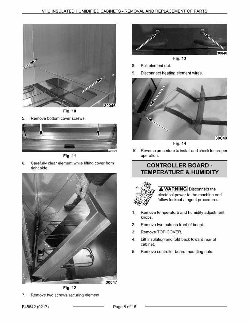
Fig. 10
5. Remove bottom cover screws.
Fig. 11
6. Carefully clear element while lifting cover fromright side.
Fig. 12
7. Remove two screws securing element.
Fig. 13
8. Pull element out.
9. Disconnect heating element wires.
Fig. 14
10. Reverse procedure to install and check for properoperation.
CONTROLLER BOARD -TEMPERATURE & HUMIDITY
Disconnect theelectrical power to the machine andfollow lockout / tagout procedures.
1. Remove temperature and humidity adjustmentknobs.
2. Remove two nuts on front of board.
3. Remove TOP COVER.
4. Lift insulation and fold back toward rear ofcabinet.
5. Remove controller board mounting nuts.
VHU INSULATED HUMIDIFIED CABINETS - REMOVAL AND REPLACEMENT OF PARTS
F45642 (0217) Page 8 of 16
Fig. 15
6. Lift controller board to access wire connections.
7. Note wire locations and disconnect fromcontroller board.
8. Reverse procedure to install and check for properoperation.
SENSOR BOARD - TEMPERATURE& HUMIDITY
Disconnect theelectrical power to the machine andfollow lockout / tagout procedures.
NOTE: Sensor board is located on top of door insidecabinet.
Sensor Board
1. Disconnect power supply.
2. Remove sensor board cover.
Fig. 16
3. Disconnect sensor wire plugs.
Fig. 17
4. Remove double-sided tape from cabinet surface.
5. Clean cabinet surface.
6. Apply double-sided tape to sensor and mount.
7. Plug sensor wire connectors into board.
8. Verify proper operation.
Sensor Board Wire Harness
1. Remove sensor board cover.
Fig. 18
2. Disconnect sensor wire plugs.
Fig. 19
3. Remove TOP COVER.
4. Disconnect wire harness plugs from board.
VHU INSULATED HUMIDIFIED CABINETS - REMOVAL AND REPLACEMENT OF PARTS
Page 9 of 16 F45642 (0217)
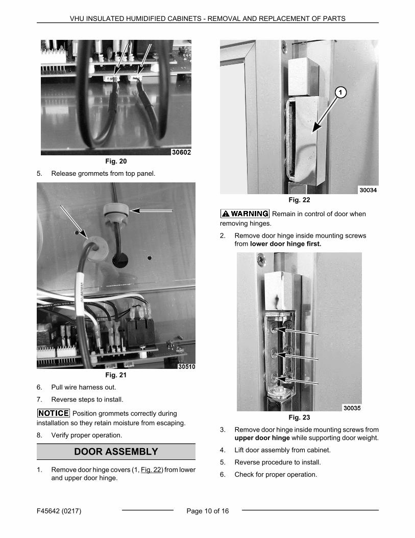
Fig. 20
5. Release grommets from top panel.
Fig. 21
6. Pull wire harness out.
7. Reverse steps to install.
Position grommets correctly duringinstallation so they retain moisture from escaping.
8. Verify proper operation.
DOOR ASSEMBLY
1. Remove door hinge covers (1, Fig. 22) from lowerand upper door hinge.
Fig. 22
Remain in control of door whenremoving hinges.
2. Remove door hinge inside mounting screwsfrom lower door hinge first.
Fig. 23
3. Remove door hinge inside mounting screws fromupper door hinge while supporting door weight.
4. Lift door assembly from cabinet.
5. Reverse procedure to install.
6. Check for proper operation.
VHU INSULATED HUMIDIFIED CABINETS - REMOVAL AND REPLACEMENT OF PARTS
F45642 (0217) Page 10 of 16
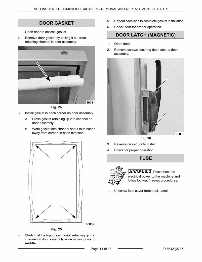
DOOR GASKET
1. Open door to access gasket.
2. Remove door gasket by pulling it out fromretaining channel in door assembly.
Fig. 24
3. Install gasket in each corner on door assembly.
A. Press gasket retaining lip into channel ondoor assembly.
B. Work gasket into channel about four inchesaway from corner, in each direction.
Fig. 25
4. Starting at the top, press gasket retaining lip intochannel on door assembly while moving towardmiddle.
5. Repeat each side to complete gasket installation.
6. Check door for proper operation.
DOOR LATCH (MAGNETIC)
1. Open door.
2. Remove screws securing door latch to doorassembly.
Fig. 26
3. Reverse procedure to install.
4. Check for proper operation.
FUSE
Disconnect theelectrical power to the machine andfollow lockout / tagout procedures.
1. Unscrew fuse cover from back panel.
VHU INSULATED HUMIDIFIED CABINETS - REMOVAL AND REPLACEMENT OF PARTS
Page 11 of 16 F45642 (0217)
2. Replace with same size and type of fuse.
3. Install cover.
FUSE HOLDER
Disconnect theelectrical power to the machine andfollow lockout / tagout procedures.
1. Remove TOP COVER.
2. Note fuse wiring and disconnect.
Fig. 28
3. Remove fuse holder mounting screws on backpanel.
Fig. 29
4. Reverse procedure to install and verify properoperation.
VHU INSULATED HUMIDIFIED CABINETS - REMOVAL AND REPLACEMENT OF PARTS
A. Unit connected to correct voltage and isproperly grounded.
B. Power switch is off.
2. Power switch turned on.
A. Relays K1, K2 and K3 are de-energized(contacts N.O.).
B. Controller board performs diagnostic testand verifies temperature and humidity inputsignals are present.
C. If no errors codes display, the temperatureand humidity settings flash in each displaywindow.
3. Fan relay K2 is energized, K2 contacts close andpower the fans.
4. Based on temperature and humidity settings, theboard determines whether K1 relay will beenergized to power element 1 (dry air); or K3relay will be energized to power element 2 (humidair).
NOTE: When temperature or humidity settings arechanged, after a brief pause, both element relays (K1& K3) will be de-energized and return to N.O. position.Heating and humidity generation stop. The relaynumbers will flash in each display window. Based ontemperature and humidity level in cabinet vs. setting,the controller board determines which relay toenergize. The number of the energized relay will flashin display window.
5. Adjust temperature and humidity to desiredlevels.