BUNN-O-MATIC COMMERCIAL PRODUCT WARRANTYBunn-O-Matic Corp. (“BUNN”) warrants equipment manufactured by it as follows:1) All equipment other than as specified below: 2 years parts and 1 year labor.2) Electronic circuit and/or control boards: parts and labor for 3 years.3) Compressors on refrigeration equipment: 5 years parts and 1 year labor.4) Grinding burrs on coffee grinding equipment to grind coffee to meet original factory screen sieve analysis: parts and labor for 3 years or 30,000 pounds of coffee, whichever comes first.These warranty periods run from the date of installation BUNN warrants that the equipment manufactured by it will be commercially free of defects in material and workmanship existing at the time of manufacture and appearing within the applicable warranty period. This warranty does not apply to any equipment, component or part that was not manufactured by BUNN or that, in BUNN’s judgment, has been affected by misuse, neglect, alteration, improper installation or operation, improper maintenance or repair, damage or casualty. This warranty is conditioned on the Buyer 1) giving BUNN prompt notice of any claim to be made under this warranty by telephone at (217) 529-6601 or by writing to Post Office Box 3227, Springfield, Illinois 62708-3227; 2) if requested by BUNN, shipping the defective equipment prepaid to an authorized BUNN service location; and 3) receiving prior authorization from BUNN that the defective equipment is under warranty.THE FOREGOING WARRANTY IS EXCLUSIVE AND IS IN LIEU OF ANY OTHER WARRANTY, WRITTEN OR ORAL, EXPRESS OR IMPLIED, INCLUDING, BUT NOT LIMITED TO, ANY IMPLIED WARRANTY OF EITHER MERCHANTABILITY OR FITNESS FOR A PARTICULAR PURPOSE. The agents, dealers or employees of BUNN are not authorized to make modifications to this warranty or to make additional warranties that are binding on BUNN. Accordingly, statements by such individuals, whether oral or written, do not constitute warranties and should not be relied upon.If BUNN determines in its sole discretion that the equipment does not conform to the warranty, BUNN, at its exclusive option while the equipment is under warranty, shall either 1) provide at no charge replacement parts and/or labor (during the applicable parts and labor warranty periods specified above) to repair the defective components, provided that this repair is done by a BUNN Authorized Service Representative; or 2) shall replace the equipment or refund the purchase price for the equipment.THE BUYER’S REMEDY AGAINST BUNN FOR THE BREACH OF ANY OBLIGATION ARISING OUT OF THE SALE OF THIS EQUIPMENT, WHETHER DERIVED FROM WARRANTY OR OTHERWISE, SHALL BE LIMITED, AT BUNN’S SOLE OPTION AS SPECIFIED HEREIN, TO REPAIR, REPLACEMENT OR REFUND.In no event shall BUNN be liable for any other damage or loss, including, but not limited to, lost profits, lost sales, loss of use of equipment, claims of Buyer’s customers, cost of capital, cost of down time, cost of substitute equipment, facilities or services, or any other special, incidental or consequential damages.
BrewWISE, BUNN Gourmet Ice, BUNN Pour-O-Matic, BUNN, Bunn-OMatic, Bunn-O-Matic, BUNNlink, BUNN-serve, BUNN Espress, DBC, Dr. Brew, Dual, EasyClear, EasyGard, Easy Pour, FlavorGard, Gourmet Ice, Gourmet Juice, High Intensity, IMIX, Infusion Series, Legendary for Quality, The Mark of Quality in Beverage Equipment Worldwide, My Café, PowerLogic, Safety-Fresh, Scale-Pro, Single, Smart Funnel, Smart Hopper, SmartWAVE, Soft Heat, SplashGard, System III, ThermoFresh, 392, AXIOM, Beverage Profit Calculator, Beverage Bar Creator, BrewLOGIC, BrewMETER, BrewWIZARD, BUNNSERVE, BUNNsource, Coffee At Its Best, Cool Froth, Digital Brewer Control, Intellisteam, Nothing Brews Like a BUNN, Pouring Profits, Pulse Wave, Quality Beverage Equip-ment Worldwide, , Signature Series, Silver Series, Smart Heat, Tea At Its Best, The Horizontal Red Line, Titan, Ultra, are either trademarks or registered trademarks of Bunn-O-Matic Corporation.
• Allelectroniccomponentshaveaclinevoltageandsomehavelowvoltagedcpotentialontheirterminals. Shorting of terminals or the application of external voltages may result in board fail-ure.
• Intermittentoperationofelectroniccircuitboardsisunlikely.Boardfailurewillnormallybeper-manent.Ifanintermittentconditionisencountered,thecausewilllikelybeaswitchcontactoraloose connection at a terminal or crimp.
WARNING • Exerciseextremecautionwhenservicingelectricalequipment. • Unplug the brewer when servicing, except when electrical tests are speci-fied. • Followrecommendedserviceprocedures. • Replaceallprotectiveshieldsorsafetynotices.
board to the plastic front end cap. This is important for proper operation. 3.Makesurebeforeservicingbrewerthatvoltageispresentatcontrolboard. 4.Pressanywarmerswitchorobserveifanyindicatorlightsareglowingonthecontrolpanel.If
Brewerhasshutdowndue tomalfunction. See Diagnostics.
Water lines and valves to the brewermustbeopen.
Check for voltage across the terminals at the terminal block.
The indicator lamp must be lit
Allowbrewertoheatuntilready,or disable the brew lockoutfeature.
Watermustbeincontactwithrefill probe before brew cyclewillstart.
Check/replace
Check/replace
Check/replace
Inspect the dispense valve and sprayhead for excessive lime deposits.Delimeasrequired.
Remove dispense valve and clear any obstructions. Rebuild or replace valve if necessary. (See page 24)
Check/replace
39132 041708
Page 8
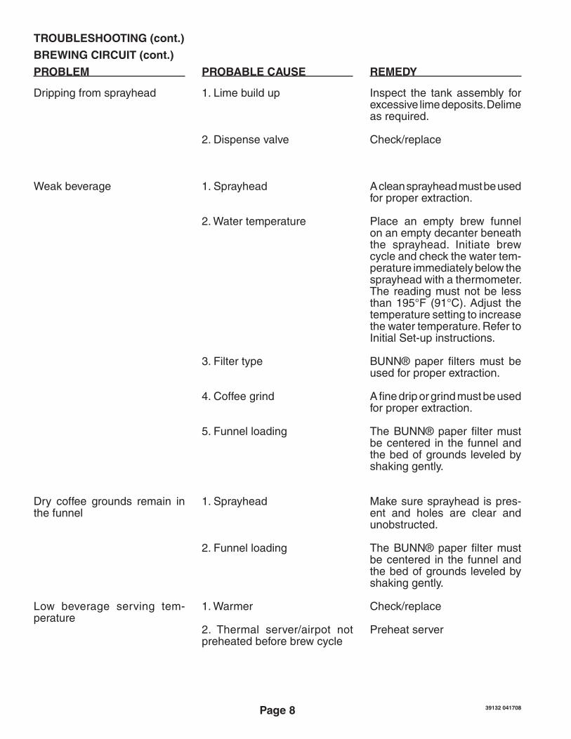
TROUBLESHOOTING (cont.)
PROBLEM PROBABLE CAUSE REMEDY
BREWING CIRCUIT (cont.)
Dripping from sprayhead
Weak beverage
Dry coffee grounds remain in the funnel
Low beverage serving tem-perature
1. Lime build up
2. Dispense valve
1. Sprayhead
2. Water temperature
3. Filter type
4. Coffee grind
5. Funnel loading
1. Sprayhead
2. Funnel loading
1. Warmer
2. Thermal server/airpot not preheatedbeforebrewcycle
Inspect the tank assembly for excessive lime deposits. Delime asrequired.
Check/replace
A clean sprayhead must be used for proper extraction.
Place an empty brew funnelon an empty decanter beneath the sprayhead. Initiate brewcycleandcheckthewatertem-peratureimmediatelybelowthesprayheadwithathermometer.The reading must not be less than195°F (91°C).Adjust thetemperature setting to increase thewatertemperature.RefertoInitial Set-up instructions.
BUNN® paper filters must beused for proper extraction.
Afinedriporgrindmustbeusedfor proper extraction.
TheBUNN®paperfiltermustbe centered in the funnel and the bed of grounds leveled by shaking gently.
Make sure sprayhead is pres-ent and holes are clear and unobstructed.
TheBUNN®paperfiltermustbe centered in the funnel and the bed of grounds leveled by shaking gently.
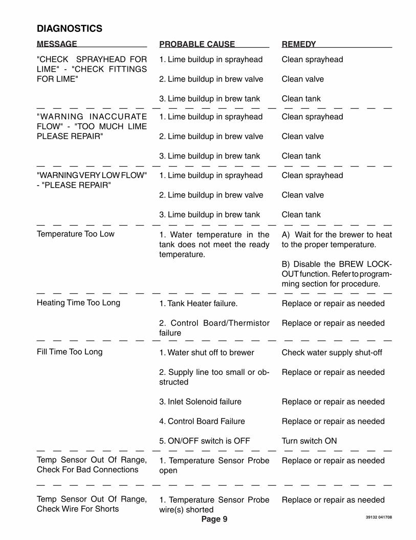
"WARNING INACCURATEFLOW" - "TOO MUCH LIMEPLEASEREPAIR"
Clean sprayhead
Clean valve
Clean tank
1. Lime buildup in sprayhead
2.Limebuildupinbrewvalve
3.Limebuildupinbrewtank
"WARNINGVERYLOWFLOW"-"PLEASEREPAIR"
Clean sprayhead
Clean valve
Clean tank
1. Lime buildup in sprayhead
2.Limebuildupinbrewvalve
3.Limebuildupinbrewtank
TemperatureTooLow
Heating Time Too Long
Fill Time Too Long
Temp Sensor Out Of Range, Check For Bad Connections
Temp Sensor Out Of Range, Check Wire For Shorts
1. Water temperature in the tank does not meet the ready temperature.
1. Tank Heater failure.
2. Control Board/Thermistor failure
1.Watershutofftobrewer
2. Supply line too small or ob-structed
3. Inlet Solenoid failure
4. Control Board Failure
5.ON/OFFswitchisOFF
1. Temperature Sensor Probe open
1. Temperature Sensor Probe wire(s)shorted
A)Waitforthebrewertoheatto the proper temperature.
B) Disable the BREW LOCK-OUT function. Refer to program-ming section for procedure.
Replace or repair as needed
Replace or repair as needed
Checkwatersupplyshut-off
Replace or repair as needed
Replace or repair as needed
Replace or repair as needed
TurnswitchON
Replace or repair as needed
Replace or repair as needed
39132 041708
Page 10
COMPONENT ACCESS
This section provides procedures for testing andreplacingvariousmajorcomponentsusedin this brewer should service become neces-sary. Refer to Troubleshooting for assistance in determining the cause of any problem.
WARNING - Inspection, testing, and repair of electricalequipmentshouldbeperformedonlybyqualifiedservicepersonnel.Thebrewershouldbeunpluggedwhenservicing,exceptwhenelec-tricaltestsarerequiredandthetestprocedurespecificallystatestopluginthebrewer.
WARNING - Disconnect the brewer from thepowersourcebeforetheremovalofanypanelor the replacement of any component.
All components are accessible by the removal ofthetopcoverorwarmerhousing,frontaccesspanelandwarmerplate(s).
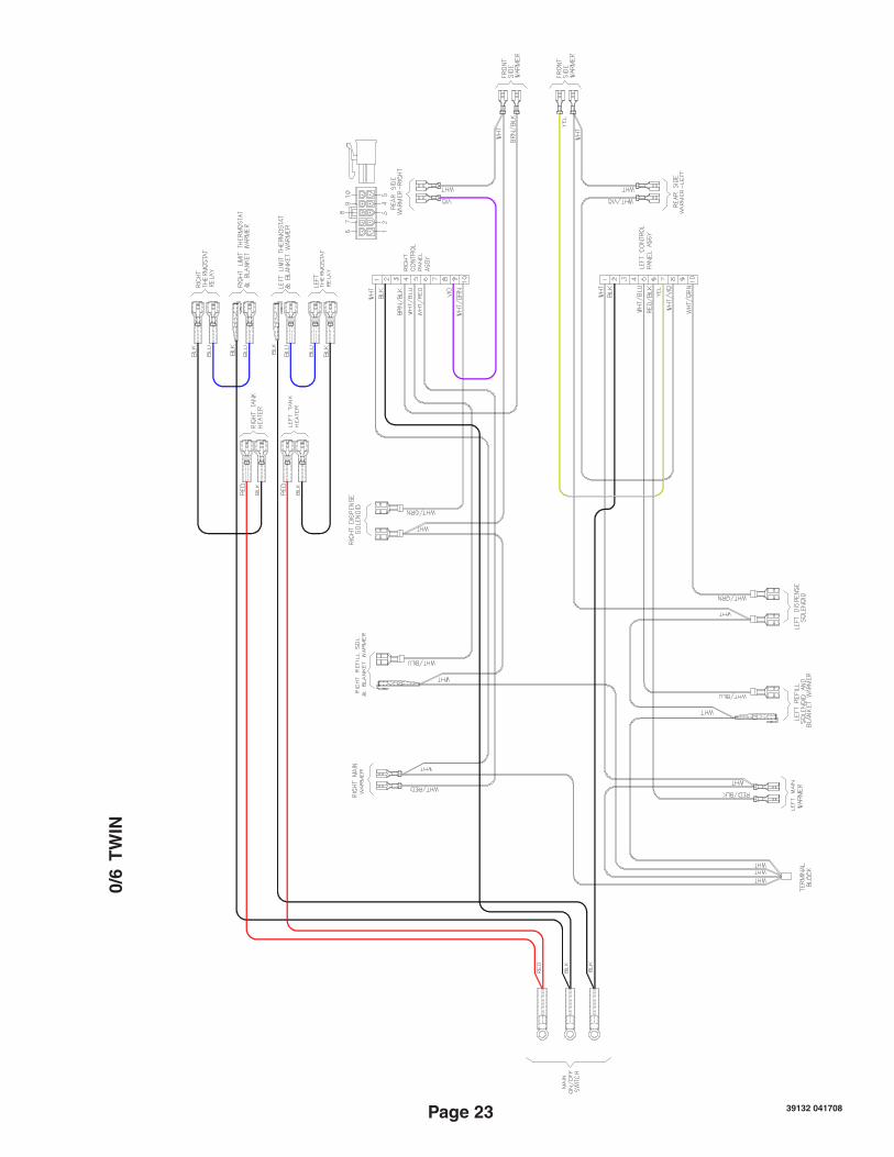
Refer to wiring diagrams at the back of this manual when reconnecting wires.
Location: The Control Board is located inside the top cover behind the front face plate.
Test Procedures: Thetestproceduresforthecontrolboardwillvary depending upon the problems experienced bythebrewer.RefertotheTroubleshootingsec-tionwhichisdividedintothreesections,RefillCircuit,HeatingCircuit,andBrewingCircuit.
Check for Power to board:1. Insert one meter lead in J1-pin 1 and theotherleadinJ1-pin2.2. With the power connected to brewer, thevoltage reading to the board should be the line voltage rated for that model.If no voltage is present, check wiring to the board. If voltage is present, and brewer does not power on, replace board.
Removal and Replacement:1. Disconnectbrewerfrompowersource.2. Disconnectthewiresfromtherelayonthecontrol board.3. Disconnect the 10-pin connector (main har-ness) and the 3-pin connector (level probe har-ness) from the control board.4. Disconnect the 10-pin connector (ribbon cable) from the control board.
FIG.11-1CONTROLBOARD
5. Removethetwoscrewsandtwonylonwash-ers securing the control board to the front face plate.6. Tilt the control board inward to clear thedisplay section.7. Place thebottomedgeof thenewcontrolboardinthetwocradles,tilttheboardforward,andsecurewiththetwoscrewsandnylonwash-ers to the front face plate.NOTE: The nylon washers must be installed under the heads of the two screws to pre-vent a possible shorting of the control board circuits.8. Re-installwires&connectors.
FaceplateRemovalandReplacement:1. Followsteps1-4above.2. Drain tank and disconnect/remove faucet.3. Remove the 3 nuts and 1 standoff from back side of faceplate assembly.4. Remove faceplate and control board as an assembly out the front opening.5. Followsteps5-7above toremove/reinstallboard.
FIG.11-2FACEPLATEREMOVAL
CONTROL BOARD
39132 041708
Page 12
Location:TheMembraneSwitch is locatedon the frontface plate.
Test Procedures: Therearetwomethodsfortestingthemem-braneswitch.Theeasiestmethodistousethebuilt in test mode. Refer to the Programing Sec-tionforServiceTools/TestSwitches.Ifforsomereason you can't get into the program modes,
FIG.12-1MEMBRANESWITCH
orbrewerwon'tpowerup,youcantest itwithan ohmmeter or continuity tester. Refer to the schematic to trace the appropriate pins.
NOTE: Pin 1 is the static shield & will not provide a reading to the other pins. There are two commons in this circuit, pins 9 & 10. #Disconnect brewer from power source before disconnecting ribbon cable from control board.
Removal and Replacement:1. Disconnect the ribbon cable from 10-pin con-nector on the control board.2. Gentlypeelthemembraneswitchfromthefront face plate assembly.4 Remove any adhesive that remains on the front face plate.5. Remove the adhesive backing from the newmembraneswitch.Inserttheribboncablethrough the slot in the front face plate and apply themembraneswitchtothefrontfaceplate.6. Install the control board to the back side of thefrontfaceplateusingthetwo#6screws&nylonwasherstothefrontfaceplateassembly.NOTE: The two nylon washers must be in-stalled under the heads of the two #6 screws to prevent a possible shorting of the control board circuits.7. Reconnect the ribbon cable to the 10-pin connector on the control board making sure every pin on the control board is inserted into the ribbon cable connector.
Wrap a thin paper clip around each meter lead and extend past the tip by ¼"-½".Youmayneedtosandofftheclear coating on some clips!
Helpful
Hint
FIG.12-2MEMBRANESWITCHCONTINUITY
MEMBRANE SWITCH
39132 041708
Page 13
Location:Thebrewvalveislocatedinsidethetopcoverbehind the front face plate.
Test Procedures:1. Refer to the Programing Section for Service Tools/TestOutputs/BrewValve.2. Besurebrewfunnel&serverare inplacebefore activating valve.3. Check the valve for coil action. Turn on the valvewiththetestmode.Listencarefullyinthevicinityofthebrewvalveforaclickasthecoilpulls the plunger in.If no sound is heard as described, proceed to #4. If the sound is heard as described, there may be a blockage in the valve , hose, tank, or sprayhead. Disconnect the brewer from the power source. Remove the valve and inspect for blockage, and de-lime all related areas.4. Connect the voltmeter leads to the coil ter-minals.Turnonthevalvewiththetestmode.NOTE: Due to the internally rectified coil, the indication will be 120VAC all the time. Set the meter to DC volts. The indication should be 170VDC when activated. If the polarity ofmeterleadsarereversed,readingwillindicate-170VDC.(Double these readings for 240 volt coils)
If voltage is present as described, but no coil ac-tionisobserved,brewvalveisdefective.Replacevalve and test again to verify repair.If voltage is not present as described, refer to WiringDiagramsandcheckthebrewerwiringharness.Alsocheckthecontrolboardandswitchfor proper operation.
Removal and Replacement:1. Disconnect the brewer from the powersource.2. Disconnectwiresfromthevalve.3. Drain enough water from the tank so thewaterlevelisbelowtheoutlet.4. Remove hoses from the valve.5. Remove the two #8-32 nuts securing thevalve to the sprayhead panel.6. Installnewvalveusingthetwo#8-32nuts.7. Reconnect hoses to the valve and secure in placewithclamps.
FIG.13-2BREWVALVE
FIG.13-1BREWVALVE
Due to the internally rectified coil, do not attempt to test this type of coil with an om-meter. The reading will be open or very high resistance, depending on the polarity of your meter leads.
Test Procedures:1. Enterprogramminglevel2,scrollto"ServiceTools"thenscrollto"RefillValve".2. Brieflyactivatetherefillvalveinthetestmode.With a voltmeter, check the voltage across the coilwires.3. Theindicationmustbe120voltsacfortwowire120voltmodelsandthreewire120/208-240voltmodelsor230voltsacfortwowire230voltmodels.If voltage is present, proceed to # 4.If voltage is not present, refer to Wiring Dia-grams and check main wiring harness. If har-ness checks ok, replace control board.4. Checktherefillvalveforcoilaction.Briefly activatetherefillvalveinthetestmodeandlistencarefullyneartherefillvalvefora"clicking"soundas the magnetic coil pulls the plunger in.If the sound is heard as described and water will not pass through the refill valve, there may be a blockage in the water line before the refill valve or, the solenoid valve may
require inspection for wear, and removal of waterborne particles.If the sound is not heard as described, pro-ceed to # 5.5. Disconnectthebrewerfromthepowersource.6. Checkforcontinuityacrosstherefillvalvecoilterminals.If continuity is not present as described, replace the refill valve.If continuity is present as described, there could be some debris in the valve.
Removal and Replacement:1. Removebothwiresfromtherefillvalve.2. Verifythatthewhiteshutoffclampbetweenvalveandtankissqueezedshut.3. Disconnectbothwaterlinesatthevalve.4. Removethetwo1/4"-20screwssecuringthevalve to the component mounting bracket. 5. Usingthetwo1/4"-20screws,installthenewvalve to the component mounting bracket.6. Securelyfastenthewaterlinestothevalve.7. Refertowiringdiagramswhenreconnectingthewires.8. Install access panels and covers and refer toInitialSet-upforrefillandoperation.
FIG.14-2REFILLVALVE
FIG.14-1REFILLVALVE
39132 041708
Page 15
FIG.15-1DVTANKHEATERS
Location:The tank heaters are located inside the tank and secured to the tank bottom.
Test Procedures:1. With a voltmeter, check voltage across
the white wire (120V Models) or red wire(120/208-240V Models) from the terminalblockandblackwirefromthecontrolboard.Connect brewer to thepower source.Theindicationmustbe120voltsacfortwowire120 volt models or 208-240 volts ac for three wire120/208-240voltmodels(duringaheat-ing cycle).
2. Disconnect the brewer from the powersource.
If voltage is present as described, proceed to #3.If voltage is not present as described, refer to theWiringDiagramsandcheckwiringharness.If harness checks ok, replace control board.
3. Disconnect thewiresfromthetankheaterterminals.
4. Check resistance value across tank heater terminals and compare to chart.
If resistance is present as described, reconnect thewires,thetankheaterisok.If resistance is not present as described, replace the tank heater.
NOTE-Ifanyresistanceisreadbetweensheathand either terminal, remove and inspect heater for cracks in the sheath.
16.Connect the two white wires of the tankwarmerblanket.
39132 041708
Page 16
LIMIT THERMOSTAT
Location:The limit thermostat is located inside the top cover on the front side of the tank.
Test Procedures:1. Disconnect the brewer from the powersource.2. Disconnectthewiresfromthelimitthermo-stat.3. With an ohmmeter, check for continuity across the limit thermostat terminals.
If continuity is present as described, the limit thermostat is operating properly.If continuity is not present as described, replace the limit thermostat.
Removal and Replacement:1. Removethewiresfromlimitthermostatter-minals.2. Carefully slide the limit thermostat out from under the retaining clip and remove limit ther-mostat.3. Carefullyslidethenewlimitthermostatintothe retaining clip. Ensure the metal face has good contactwithtank.
FIG.16-2LIMITTHERMOSTAT
FIG.16-1TCOCHECK
THERMALCUTOFF(230V MODELS ONLY)
Location:The TCO's are located under the tank at the heater connections.
Test Procedures:1. Disconnect the brewer from the powersource.2. Disconnect the TCO from the tank heater.3. With an ohmmeter, check for continuity across theTCOasshownabove.
If continuity is not present as described, replace the main harness.
39132 041708
Page 17
Location:
Theblanketwarmeriswrappedaroundthetank assembly.
Test Procedures:1. Disconnect the brewer from the power
source.2. With a voltmeter, check voltage across the
two wires at the warmer element with the"ON/OFF"switchinthe"ON"position.Con-nect the brewer to the power source.Theindicationmustbe120voltsacfortwowire120voltmodelsandthreewire120/208and120/240voltmodels,or230voltsacfortwowire230voltmodels.
3. Disconnect the brewer from the powersource.
If voltage is present as described, proceed to #4.If voltage is not present as described, refer to WiringDiagramsandcheckwiringharness.
tom of blanket 1½˝ from bottom of tank.5. Connectoneof thewhitewiresto thepig-
gyback terminal on the limit thermostat.6. Reinstall tank assembly.7. Connecttheotherwhitewiretothepiggyback
terminalontherefillvalve.FIG.17-1BLANKETWARMER
BLANKETWARMER
50W-120V 288.050W-220V 968.0
WARMER RESISTANCE
39132 041708
Page 18
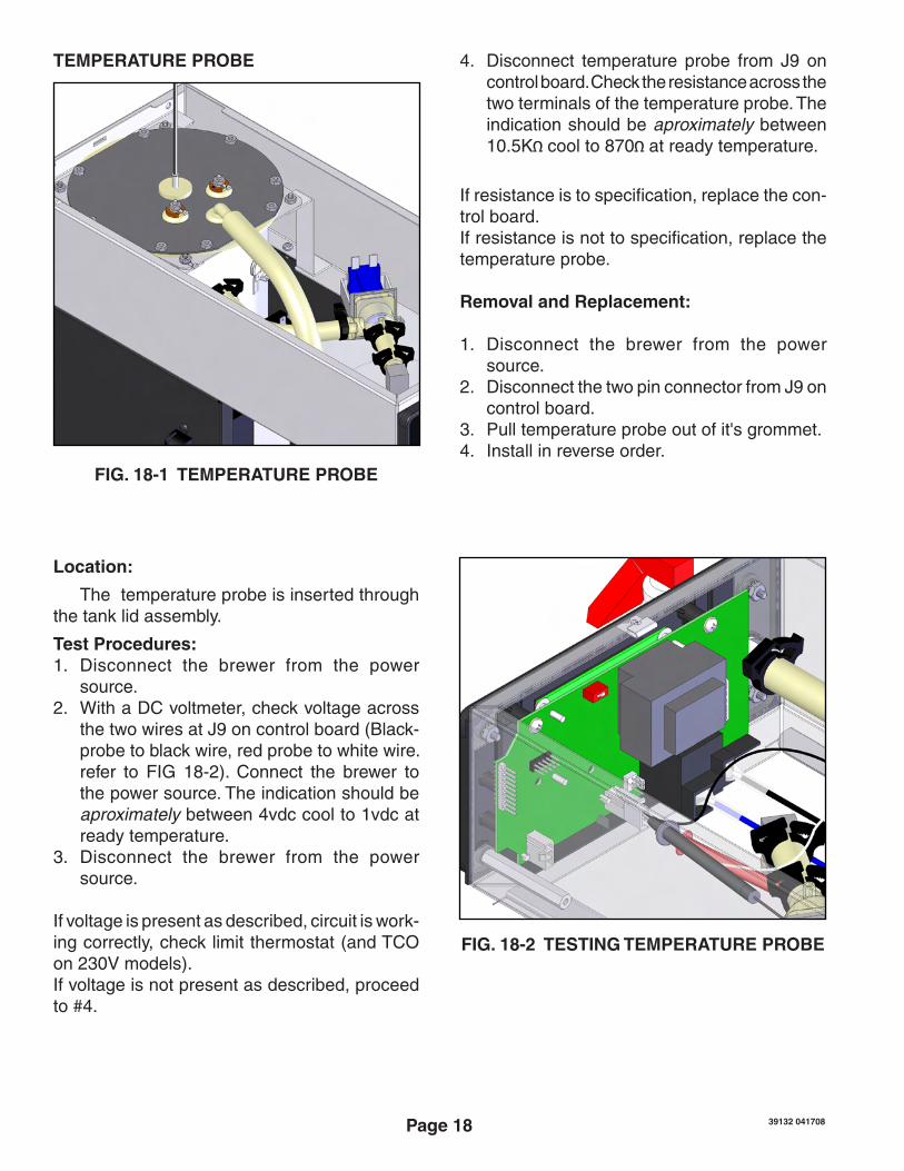
Location:
The temperature probe is inserted through the tank lid assembly.
Test Procedures:1. Disconnect the brewer from the power
source.2. With a DC voltmeter, check voltage across
thetwowiresatJ9oncontrolboard(Black-probetoblackwire,redprobetowhitewire.refer to FIG 18-2). Connect the brewer tothepowersource.Theindicationshouldbeaproximatelybetween4vdccoolto1vdcatready temperature.
3. Disconnect the brewer from the powersource.
Ifvoltageispresentasdescribed,circuitiswork-ing correctly, check limit thermostat (and TCO on230Vmodels).If voltage is not present as described, proceed to#4.
4. Disconnect temperature probe from J9 oncontrol board. Check the resistance across the twoterminalsofthetemperatureprobe.Theindication should be aproximatelybetween10.5K cool to 870 at ready temperature.
3. Pull temperature probe out of it's grommet.4. Install in reverse order.
FIG.18-1TEMPERATUREPROBE
TEMPERATURE PROBE
FIG.18-2TESTINGTEMPERATUREPROBE
39132 041708
Page 19
Location:
Thewarmerelement(s)islocatedunderthewarmerplate.
Test Procedures:1. Disconnect the brewer from the power
source.2. With a voltmeter, check voltage across the
two wires at the warmer element with the"ON/OFF"switchinthe"ON"position.Con-nect the brewer to the power source.Theindicationmustbe120voltsacfortwowire120voltmodelsandthreewire120/208and120/240voltmodels,or230voltsacfortwowire230voltmodels.
3. Disconnect the brewer from the powersource.
If voltage is present as described, proceed to #4.If voltage is not present as described, refer to WiringDiagramsandcheckwiringharness.