27
BULLETIN NO. TEH-1208 Pump Selection for Building Service Systems Bell & Gossett ®
BULLETIN NO. TEH-1208
Pump Selection for Building Service Systems
Bell & Gossett®
© Copyright © 2010 ITT CorporationPrinted in U.S.A. 1-10
THE ITT ENGINEERED BLOCKS SYMBOL AND ENGINEERED FOR LIFE ARE REGISTERED TRADEMARKS OF ITT MANUFACTURING ENTERPRISES, INC.
ITT8200 N. Austin AvenueMorton Grove, IL 60053 Phone: (847) 966-3700Fax: (847) 966-9052www.bellgossett.com
ITT
07152A Cov.indd 2-3 1/21/10 1:50 PM
2
TABLE OF CONTENTSIntroduction.................................................................................................................................................................. 1Centrifugal.Pumps........................................................................................................................................................ 1
Major.Components.................................................................................................................................................. 1Bernoulli's.Principle.................................................................................................................................................. 1
Centrifugal.Impellers..................................................................................................................................................... 2Pump.types................................................................................................................................................................... 4
Single.Suction.Pumps............................................................................................................................................... 5Internal.Components............................................................................................................................................. 5Mechanical.Seal.................................................................................................................................................... 5Seal.Limits............................................................................................................................................................. 6
Close-Coupled.Pumps................................................................................................................................................... 7Multi-Stage.Pumps....................................................................................................................................................... 8
Vertical.Turbine.Pumps.................................................................................................................................................. 8
Double.Suction.Pumps.................................................................................................................................................. 9
Pump.Installation.Details.............................................................................................................................................. 9
Suction.Conditions........................................................................................................................................................ 9
Suction.Diffuser.......................................................................................................................................................... 10
Discharge.Conditions.................................................................................................................................................. 11
Triple.Duty®.Valves..................................................................................................................................................... 11
Pump.Foundation....................................................................................................................................................... 11Flexible.Connectors................................................................................................................................................ 12Pipe.Supports........................................................................................................................................................ 12Pressure.Gauges.................................................................................................................................................... 12
Summary.................................................................................................................................................................... 12Life.Cycle.Costs........................................................................................................................................................... 13Pump.Selection........................................................................................................................................................... 13
As.a.Decision-Making.Process................................................................................................................................ 13For.known.flow.and.head.conditions..................................................................................................................... 14Fixed.Flow.System................................................................................................................................................. 14Variable.Flow.System............................................................................................................................................. 14Variable.Flow,.Fixed.Head.System.......................................................................................................................... 14
System.Curve.............................................................................................................................................................. 14Moody.Chart.......................................................................................................................................................... 15Riding.The.Curve................................................................................................................................................... 16
Volute.Choices............................................................................................................................................................ 17Base.Mounted.Versus.In-Line................................................................................................................................. 17Flexibly.Coupled.Versus.Close-Coupled.................................................................................................................. 17Single.Suction.Versus.Double.Suction..................................................................................................................... 17Selection.Strategies................................................................................................................................................ 17Best.Efficiency.Point.and.Preferred.Selection.Region............................................................................................... 17
Maximum.Impeller.Diameter.Limits............................................................................................................................. 18RPM.Choices............................................................................................................................................................... 19Pump.Selection-General.Considerations...................................................................................................................... 19System.Design............................................................................................................................................................ 20Summary.................................................................................................................................................................... 23
07152A Cov.indd 4-5 1/21/10 1:50 PM
1
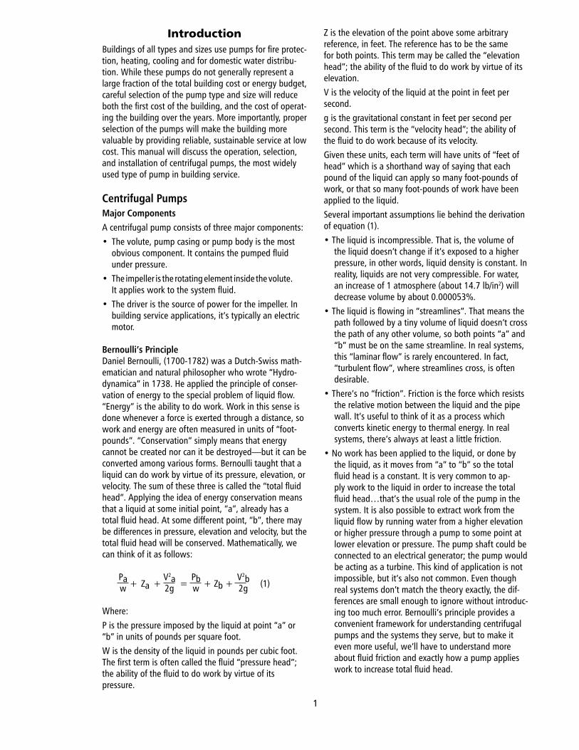
IntroductionBuildings.of.all.types.and.sizes.use.pumps.for.fire.protec-tion,.heating,.cooling.and.for.domestic.water.distribu-tion..While.these.pumps.do.not.generally.represent.a.large.fraction.of.the.total.building.cost.or.energy.budget,.careful.selection.of.the.pump.type.and.size.will.reduce.both.the.first.cost.of.the.building,.and.the.cost.of.operat-ing.the.building.over.the.years..More.importantly,.proper.selection.of.the.pumps.will.make.the.building.more.valuable.by.providing.reliable,.sustainable.service.at.low.cost..This.manual.will.discuss.the.operation,.selection,.and.installation.of.centrifugal.pumps,.the.most.widely.used.type.of.pump.in.building.service.
Centrifugal PumpsMajor ComponentsA.centrifugal.pump.consists.of.three.major.components:•. The.volute,.pump.casing.or.pump.body.is.the.most. .. obvious.component..It.contains.the.pumped.fluid.. .. under.pressure.•. The.impeller.is.the.rotating.element.inside.the.volute..... It.applies.work.to.the.system.fluid.•. The.driver.is.the.source.of.power.for.the.impeller..In.. .. building.service.applications,.it’s.typically.an.electric.. .. motor.
Bernoulli’s PrincipleDaniel.Bernoulli,.(1700-1782).was.a.Dutch-Swiss.math-ematician.and.natural.philosopher.who.wrote.“Hydro-dynamica”.in.1738..He.applied.the.principle.of.conser-vation.of.energy.to.the.special.problem.of.liquid.flow...“Energy”.is.the.ability.to.do.work..Work.in.this.sense.is.done.whenever.a.force.is.exerted.through.a.distance,.so.work.and.energy.are.often.measured.in.units.of.“foot-pounds”..“Conservation”.simply.means.that.energy.cannot.be.created.nor.can.it.be.destroyed—but.it.can.be.converted.among.various.forms..Bernoulli.taught.that.a.liquid.can.do.work.by.virtue.of.its.pressure,.elevation,.or.velocity..The.sum.of.these.three.is.called.the.“total.fluid.head”..Applying.the.idea.of.energy.conservation.means.that.a.liquid.at.some.initial.point,.“a”,.already.has.a.total.fluid.head..At.some.different.point,.“b”,.there.may.be.differences.in.pressure,.elevation.and.velocity,.but.the.total.fluid.head.will.be.conserved..Mathematically,.we.can.think.of.it.as.follows:
. Pa.+
.Za
.+
.V2a.=
. Pb.+
.Zb
.+
. V2b. (1). w. . . . 2g. . w. . . . 2g
Where:P.is.the.pressure.imposed.by.the.liquid.at.point.“a”.or.“b”.in.units.of.pounds.per.square.foot...W.is.the.density.of.the.liquid.in.pounds.per.cubic.foot...The.first.term.is.often.called.the.fluid.“pressure.head”;.the.ability.of.the.fluid.to.do.work.by.virtue.of.its..pressure.
Z.is.the.elevation.of.the.point.above.some.arbitrary.reference,.in.feet..The.reference.has.to.be.the.same.for.both.points..This.term.may.be.called.the.“elevation.head”;.the.ability.of.the.fluid.to.do.work.by.virtue.of.its.elevation.V.is.the.velocity.of.the.liquid.at.the.point.in.feet.per.second.g.is.the.gravitational.constant.in.feet.per.second.per.second..This.term.is.the.“velocity.head”;.the.ability.of.the.fluid.to.do.work.because.of.its.velocity.Given.these.units,.each.term.will.have.units.of.“feet.of.head”.which.is.a.shorthand.way.of.saying.that.each.pound.of.the.liquid.can.apply.so.many.foot-pounds.of.work,.or.that.so.many.foot-pounds.of.work.have.been.applied.to.the.liquid.Several.important.assumptions.lie.behind.the.derivation.of.equation.(1).•..The.liquid.is.incompressible..That.is,.the.volume.of.
the.liquid.doesn’t.change.if.it’s.exposed.to.a.higher.pressure,.in.other.words,.liquid.density.is.constant..In.reality,.liquids.are.not.very.compressible..For.water,.an.increase.of.1.atmosphere.(about.14.7.lb/in2).will.decrease.volume.by.about.0.000053%..
•..The.liquid.is.flowing.in.“streamlines”..That.means.the.path.followed.by.a.tiny.volume.of.liquid.doesn’t.cross.the.path.of.any.other.volume,.so.both.points.“a”.and.“b”.must.be.on.the.same.streamline..In.real.systems,.this.“laminar.flow”.is.rarely.encountered..In.fact,.“turbulent.flow”,.where.streamlines.cross,.is.often.desirable.
•..There’s.no.“friction”..Friction.is.the.force.which.resists.the.relative.motion.between.the.liquid.and.the.pipe.wall..It’s.useful.to.think.of.it.as.a.process.which.converts.kinetic.energy.to.thermal.energy..In.real.systems,.there’s.always.at.least.a.little.friction.
•..No.work.has.been.applied.to.the.liquid,.or.done.by.the.liquid,.as.it.moves.from.“a”.to.“b”.so.the.total.fluid.head.is.a.constant..It.is.very.common.to.ap-ply.work.to.the.liquid.in.order.to.increase.the.total.fluid.head…that’s.the.usual.role.of.the.pump.in.the.system..It.is.also.possible.to.extract.work.from.the.liquid.flow.by.running.water.from.a.higher.elevation.or.higher.pressure.through.a.pump.to.some.point.at.lower.elevation.or.pressure..The.pump.shaft.could.be.connected.to.an.electrical.generator;.the.pump.would.be.acting.as.a.turbine..This.kind.of.application.is.not.impossible,.but.it’s.also.not.common..Even.though.real.systems.don’t.match.the.theory.exactly,.the.dif-ferences.are.small.enough.to.ignore.without.introduc-ing.too.much.error..Bernoulli’s.principle.provides.a.convenient.framework.for.understanding.centrifugal.pumps.and.the.systems.they.serve,.but.to.make.it.even.more.useful,.we’ll.have.to.understand.more.about.fluid.friction.and.exactly.how.a.pump.applies.work.to.increase.total.fluid.head.
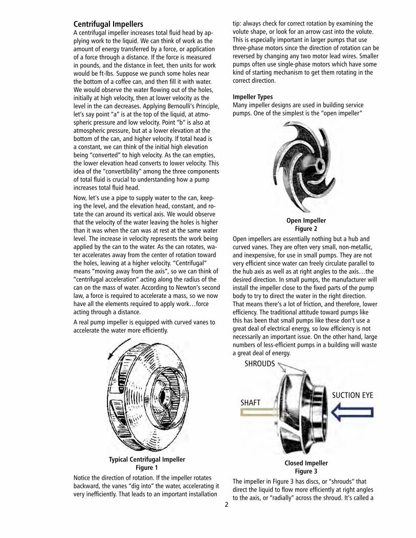
Centrifugal ImpellersA.centrifugal.impeller.increases.total.fluid.head.by.ap-plying.work.to.the.liquid..We.can.think.of.work.as.the.amount.of.energy.transferred.by.a.force,.or.application.of.a.force.through.a.distance..If.the.force.is.measured.in.pounds,.and.the.distance.in.feet,.then.units.for.work.would.be.ft-lbs..Suppose.we.punch.some.holes.near.the.bottom.of.a.coffee.can,.and.then.fill.it.with.water..We.would.observe.the.water.flowing.out.of.the.holes,.initially.at.high.velocity,.then.at.lower.velocity.as.the.level.in.the.can.decreases..Applying.Bernoulli’s.Principle,.let’s.say.point.“a”.is.at.the.top.of.the.liquid,.at.atmo-spheric.pressure.and.low.velocity..Point.“b”.is.also.at.atmospheric.pressure,.but.at.a.lower.elevation.at.the.bottom.of.the.can,.and.higher.velocity..If.total.head.is.a.constant,.we.can.think.of.the.initial.high.elevation.being.“converted”.to.high.velocity..As.the.can.empties,.the.lower.elevation.head.converts.to.lower.velocity..This.idea.of.the.“convertibility”.among.the.three.components.of.total.fluid.is.crucial.to.understanding.how.a.pump.increases.total.fluid.head.Now,.let’s.use.a.pipe.to.supply.water.to.the.can,.keep-ing.the.level,.and.the.elevation.head,.constant,.and.ro-tate.the.can.around.its.vertical.axis..We.would.observe.that.the.velocity.of.the.water.leaving.the.holes.is.higher.than.it.was.when.the.can.was.at.rest.at.the.same.water.level..The.increase.in.velocity.represents.the.work.being.applied.by.the.can.to.the.water..As.the.can.rotates,.wa-ter.accelerates.away.from.the.center.of.rotation.toward.the.holes,.leaving.at.a.higher.velocity..“Centrifugal”.means.“moving.away.from.the.axis”,.so.we.can.think.of.“centrifugal.acceleration”.acting.along.the.radius.of.the.can.on.the.mass.of.water..According.to.Newton’s.second.law,.a.force.is.required.to.accelerate.a.mass,.so.we.now.have.all.the.elements.required.to.apply.work…force.acting.through.a.distance.A.real.pump.impeller.is.equipped.with.curved.vanes.to.accelerate.the.water.more.efficiently.
Typical Centrifugal ImpellerFigure 1
Notice.the.direction.of.rotation..If.the.impeller.rotates.backward,.the.vanes.“dig.into”.the.water,.accelerating.it.very.inefficiently..That.leads.to.an.important.installation.
tip:.always.check.for.correct.rotation.by.examining.the.volute.shape,.or.look.for.an.arrow.cast.into.the.volute..This.is.especially.important.in.larger.pumps.that.use.three-phase.motors.since.the.direction.of.rotation.can.be.reversed.by.changing.any.two.motor.lead.wires..Smaller.pumps.often.use.single-phase.motors.which.have.some.kind.of.starting.mechanism.to.get.them.rotating.in.the.correct.direction.
Impeller TypesMany.impeller.designs.are.used.in.building.service.pumps..One.of.the.simplest.is.the.“open.impeller”
Open ImpellerFigure 2
Open.impellers.are.essentially.nothing.but.a.hub.and.curved.vanes..They.are.often.very.small,.non-metallic,.and.inexpensive,.for.use.in.small.pumps..They.are.not.very.efficient.since.water.can.freely.circulate.parallel.to.the.hub.axis.as.well.as.at.right.angles.to.the.axis…the.desired.direction..In.small.pumps,.the.manufacturer.will.install.the.impeller.close.to.the.fixed.parts.of.the.pump.body.to.try.to.direct.the.water.in.the.right.direction..That.means.there’s.a.lot.of.friction,.and.therefore,.lower.efficiency..The.traditional.attitude.toward.pumps.like.this.has.been.that.small.pumps.like.these.don’t.use.a.great.deal.of.electrical.energy,.so.low.efficiency.is.not.necessarily.an.important.issue..On.the.other.hand,.large.numbers.of.less-efficient.pumps.in.a.building.will.waste.a.great.deal.of.energy.
Closed ImpellerFigure 3
The.impeller.in.Figure.3.has.discs,.or.“shrouds”.that.direct.the.liquid.to.flow.more.efficiently.at.right.angles.to.the.axis,.or.“radially”.across.the.shroud..It’s.called.a.
SHROUDS
SHAFTSUCTION.EYE
2
“closed.impeller”,.and.because.of.its.better.efficiency,.it’s.much.more.widely.used,.especially.in.larger.pumps.that.can.handle.larger.flow.rates,.and.therefore.require.greater.energy.input..The.impeller.in.Figure.3.is.also.called.a.“single.suction.impeller”.since.all.the.liquid.inters.the.“suction.eye”.on.the.same.side.of.the.impeller..This.will.exert.large.axial.forces.on.the.bearings.that.support.the.shaft.A.“double.suction”.impeller.is.often.used.to.minimize.axial.forces.on.the.pump.shaft.
Double Suction Closed ImpellerFigure 4
If.the.liquid.enters.both.sides.of.the.impeller.equally,.the.axial.forces.cancel,.meaning.that.the.shaft.bearings.don’t.need.to.oppose.any.significant.axial.loading..There.are.several.other.good.reasons.for.using.double.suction.impellers.to.handle.higher.flow.rates..We’ll.discuss.them.later.Some.building.pumps.like.sewage.ejectors.and.sump.pumps.must.handle.large.solids.that.would.clog.a.closed.impeller..These.pumps.would.use.a.“non-clog-ging”.impeller.like.the.one.in.Figure.5.
Non-Clogging ImpellerFigure 5
Notice.that.it.has.no.shrouds.and.only.a.few.vanes..Some.impellers.in.sewage.pumps.can.actually.grind.the.solids.to.smaller.pieces.that.can.flow.through.the.pump.and.piping..“Clean.water”.applications.don’t.need.these.special.impellers;.they.can.use.more.efficient.closed.impellers..Hot.or.cold.tap.water.certainly.qualifies.as.“clean.water”..In.fact,.there.are.special.requirements.for.potable.water.equipment.to.insure.that.germs.and.bacteria.won’t.be.spread.through.the.water.supply..Systems.that.use.water.to.heat.and.cool.the.building.are.also.classified.as.clean.water.systems..Even.though.the.liquid.in.those.systems.may.contain.small.solid.particles.or.other.things.that.would.make.it.unfit.for.consump-tion,.the.pump.can.still.use.a.closed.impeller.
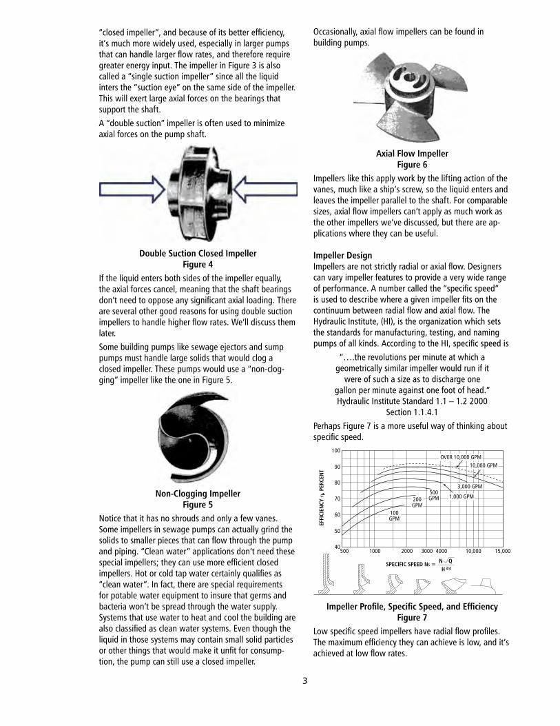
Occasionally,.axial.flow.impellers.can.be.found.in..building.pumps.
Axial Flow ImpellerFigure 6
Impellers.like.this.apply.work.by.the.lifting.action.of.the.vanes,.much.like.a.ship’s.screw,.so.the.liquid.enters.and.leaves.the.impeller.parallel.to.the.shaft..For.comparable.sizes,.axial.flow.impellers.can’t.apply.as.much.work.as.the.other.impellers.we’ve.discussed,.but.there.are.ap-plications.where.they.can.be.useful.
Impeller DesignImpellers.are.not.strictly.radial.or.axial.flow..Designers.can.vary.impeller.features.to.provide.a.very.wide.range.of.performance..A.number.called.the.“specific.speed”.is.used.to.describe.where.a.given.impeller.fits.on.the.continuum.between.radial.flow.and.axial.flow..The.Hydraulic.Institute,.(HI),.is.the.organization.which.sets.the.standards.for.manufacturing,.testing,.and.naming.pumps.of.all.kinds..According.to.the.HI,.specific.speed.is
“….the.revolutions.per.minute.at.which.ageometrically.similar.impeller.would.run.if.it
were.of.such.a.size.as.to.discharge.onegallon.per.minute.against.one.foot.of.head.”.Hydraulic.Institute.Standard.1.1.–.1.2.2000
Section.1.1.4.1Perhaps.Figure.7.is.a.more.useful.way.of.thinking.about.specific.speed.
Impeller Profile, Specific Speed, and EfficiencyFigure 7
Low.specific.speed.impellers.have.radial.flow.profiles..The.maximum.efficiency.they.can.achieve.is.low,.and.it’s.achieved.at.low.flow.rates.
EFFI
CIEN
CY η
, PER
CEN
T
100
90
80
70
60
50
40500 1000 2000 3000 4000 10,000 15,000
100GPM
200GPM
500GPM 1,000 GPM
3,000 GPM
10,000 GPMOVER 10,000 GPM
SPECIFIC SPEED NS = N QH 3/4
3
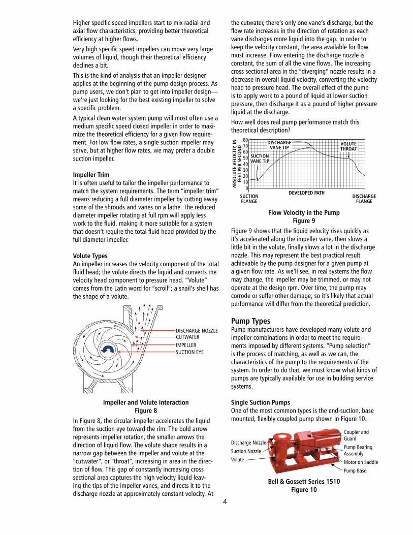
Higher.specific.speed.impellers.start.to.mix.radial.and.axial.flow.characteristics,.providing.better.theoretical.efficiency.at.higher.flows.Very.high.specific.speed.impellers.can.move.very.large.volumes.of.liquid,.though.their.theoretical.efficiency.declines.a.bit.This.is.the.kind.of.analysis.that.an.impeller.designer.applies.at.the.beginning.of.the.pump.design.process..As.pump.users,.we.don’t.plan.to.get.into.impeller.design—we’re.just.looking.for.the.best.existing.impeller.to.solve.a.specific.problem.A.typical.clean.water.system.pump.will.most.often.use.a.medium.specific.speed.closed.impeller.in.order.to.maxi-mize.the.theoretical.efficiency.for.a.given.flow.require-ment..For.low.flow.rates,.a.single.suction.impeller.may.serve,.but.at.higher.flow.rates,.we.may.prefer.a.double.suction.impeller.
Impeller TrimIt.is.often.useful.to.tailor.the.impeller.performance.to.match.the.system.requirements..The.term.“impeller.trim”.means.reducing.a.full.diameter.impeller.by.cutting.away.some.of.the.shrouds.and.vanes.on.a.lathe..The.reduced.diameter.impeller.rotating.at.full.rpm.will.apply.less.work.to.the.fluid,.making.it.more.suitable.for.a.system.that.doesn’t.require.the.total.fluid.head.provided.by.the.full.diameter.impeller.
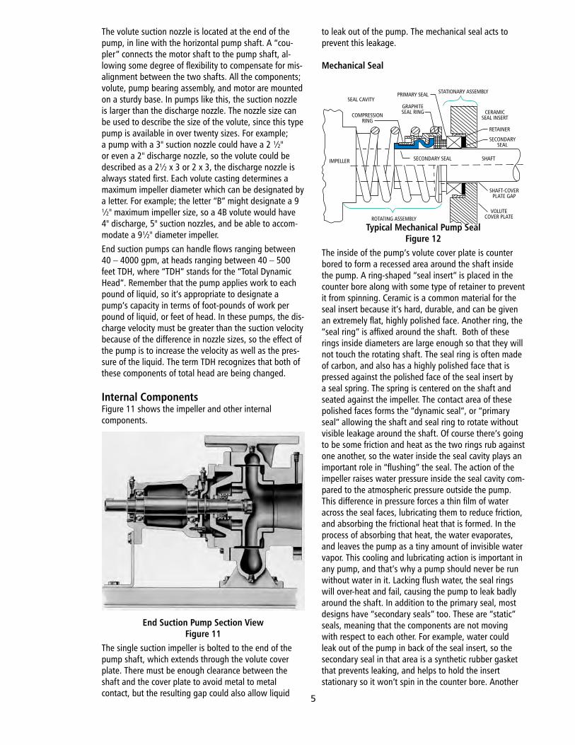
Volute TypesAn.impeller.increases.the.velocity.component.of.the.total.fluid.head;.the.volute.directs.the.liquid.and.converts.the.velocity.head.component.to.pressure.head..“Volute”.comes.from.the.Latin.word.for.“scroll”;.a.snail’s.shell.has.the.shape.of.a.volute.
Impeller and Volute InteractionFigure 8
In.Figure.8,.the.circular.impeller.accelerates.the.liquid.from.the.suction.eye.toward.the.rim..The.bold.arrow.represents.impeller.rotation,.the.smaller.arrows.the.direction.of.liquid.flow..The.volute.shape.results.in.a.narrow.gap.between.the.impeller.and.volute.at.the.“cutwater”,.or.“throat”,.increasing.in.area.in.the.direc-tion.of.flow..This.gap.of.constantly.increasing.cross.sectional.area.captures.the.high.velocity.liquid.leav-ing.the.tips.of.the.impeller.vanes,.and.directs.it.to.the.discharge.nozzle.at.approximately.constant.velocity..At.
the.cutwater,.there’s.only.one.vane’s.discharge,.but.the.flow.rate.increases.in.the.direction.of.rotation.as.each.vane.discharges.more.liquid.into.the.gap..In.order.to.keep.the.velocity.constant,.the.area.available.for.flow.must.increase..Flow.entering.the.discharge.nozzle.is.constant,.the.sum.of.all.the.vane.flows..The.increasing.cross.sectional.area.in.the.“diverging”.nozzle.results.in.a.decrease.in.overall.liquid.velocity,.converting.the.velocity.head.to.pressure.head..The.overall.effect.of.the.pump.is.to.apply.work.to.a.pound.of.liquid.at.lower.suction.pressure,.then.discharge.it.as.a.pound.of.higher.pressure.liquid.at.the.discharge.How.well.does.real.pump.performance.match.this..theoretical.description?
Flow Velocity in the PumpFigure 9
Figure.9.shows.that.the.liquid.velocity.rises.quickly.as.it’s.accelerated.along.the.impeller.vane,.then.slows.a.little.bit.in.the.volute,.finally.slows.a.lot.in.the.discharge.nozzle..This.may.represent.the.best.practical.result.achievable.by.the.pump.designer.for.a.given.pump.at.a.given.flow.rate..As.we’ll.see,.in.real.systems.the.flow.may.change,.the.impeller.may.be.trimmed,.or.may.not.operate.at.the.design.rpm..Over.time,.the.pump.may.corrode.or.suffer.other.damage;.so.it’s.likely.that.actual.performance.will.differ.from.the.theoretical.prediction.
Pump TypesPump.manufacturers.have.developed.many.volute.and.impeller.combinations.in.order.to.meet.the.require-ments.imposed.by.different.systems..“Pump.selection”.is.the.process.of.matching,.as.well.as.we.can,.the.characteristics.of.the.pump.to.the.requirements.of.the.system..In.order.to.do.that,.we.must.know.what.kinds.of.pumps.are.typically.available.for.use.in.building.service.systems.
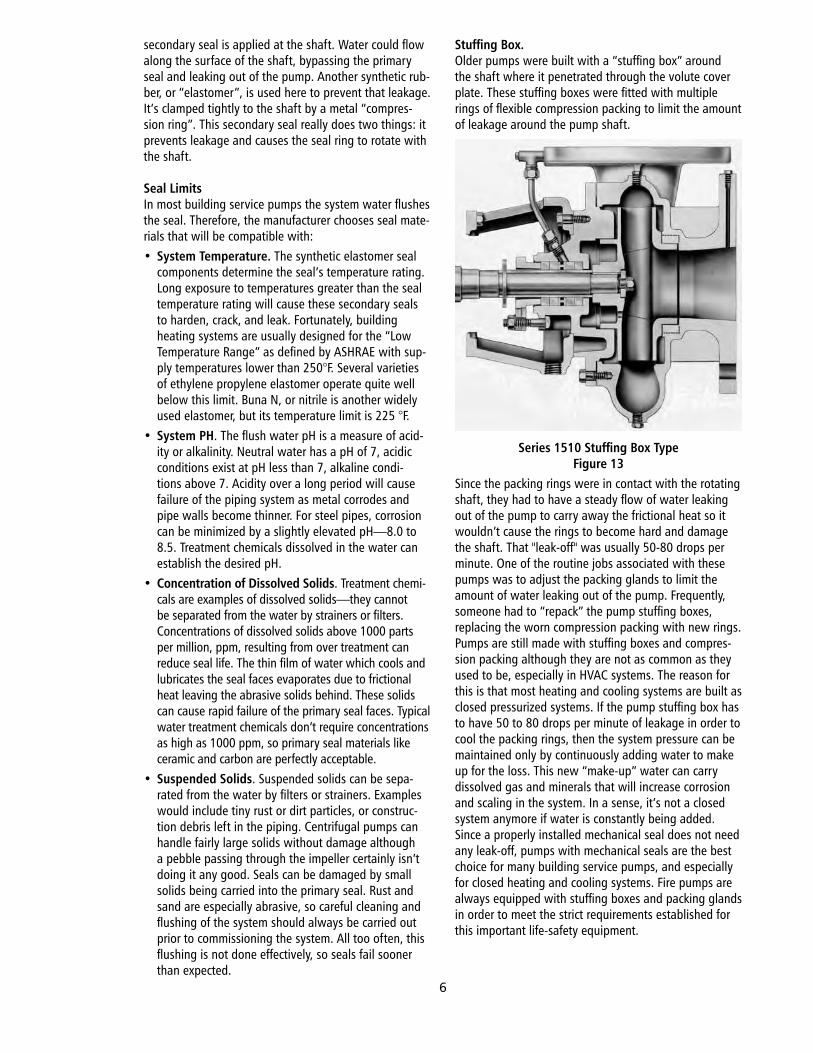
Single Suction PumpsOne.of.the.most.common.types.is.the.end-suction,.base.mounted,.flexibly.coupled.pump.shown.in.Figure.10.
Bell & Gossett Series 1510Figure 10
DISCHARGE NOZZLECUTWATERIMPELLERSUCTION EYE
DEVELOPED PATHSUCTIONFLANGE
DISCHARGEFLANGE
ABSO
LUTE
VEL
OCI
TY, I
NFE
ET P
ER S
ECO
ND
8070605040302010
0
SUCTIONVANE TIP
DISCHARGEVANE TIP
VOLUTETHROAT
Coupler.and.. .Guard
Pump.Bearing.. .Assembly
Motor.on.Saddle
Pump.Base
Discharge.Nozzle
Suction.Nozzle
Volute
4
The.volute.suction.nozzle.is.located.at.the.end.of.the.pump,.in.line.with.the.horizontal.pump.shaft..A.“cou-pler”.connects.the.motor.shaft.to.the.pump.shaft,.al-lowing.some.degree.of.flexibility.to.compensate.for.mis-alignment.between.the.two.shafts..All.the.components;.volute,.pump.bearing.assembly,.and.motor.are.mounted.on.a.sturdy.base..In.pumps.like.this,.the.suction.nozzle.is.larger.than.the.discharge.nozzle..The.nozzle.size.can.be.used.to.describe.the.size.of.the.volute,.since.this.type.pump.is.available.in.over.twenty.sizes..For.example;.a.pump.with.a.3".suction.nozzle.could.have.a.2.½".or.even.a.2".discharge.nozzle,.so.the.volute.could.be.described.as.a.2½.x.3.or.2.x.3,.the.discharge.nozzle.is.always.stated.first..Each.volute.casting.determines.a.maximum.impeller.diameter.which.can.be.designated.by.a.letter..For.example;.the.letter.“B”.might.designate.a.9.½".maximum.impeller.size,.so.a.4B.volute.would.have.4".discharge,.5".suction.nozzles,.and.be.able.to.accom-modate.a.9½".diameter.impeller.End.suction.pumps.can.handle.flows.ranging.between.40.–.4000.gpm,.at.heads.ranging.between.40.–.500.feet.TDH,.where.“TDH”.stands.for.the.“Total.Dynamic.Head”..Remember.that.the.pump.applies.work.to.each.pound.of.liquid,.so.it’s.appropriate.to.designate.a.pump’s.capacity.in.terms.of.foot-pounds.of.work.per.pound.of.liquid,.or.feet.of.head..In.these.pumps,.the.dis-charge.velocity.must.be.greater.than.the.suction.velocity.because.of.the.difference.in.nozzle.sizes,.so.the.effect.of.the.pump.is.to.increase.the.velocity.as.well.as.the.pres-sure.of.the.liquid..The.term.TDH.recognizes.that.both.of.these.components.of.total.head.are.being.changed.
Internal ComponentsFigure.11.shows.the.impeller.and.other.internal..components.
End Suction Pump Section ViewFigure 11
The.single.suction.impeller.is.bolted.to.the.end.of.the.pump.shaft,.which.extends.through.the.volute.cover.plate..There.must.be.enough.clearance.between.the.shaft.and.the.cover.plate.to.avoid.metal.to.metal..contact,.but.the.resulting.gap.could.also.allow.liquid.
to.leak.out.of.the.pump..The.mechanical.seal.acts.to.prevent.this.leakage.
Mechanical Seal
Typical Mechanical Pump SealFigure 12
The.inside.of.the.pump’s.volute.cover.plate.is.counter.bored.to.form.a.recessed.area.around.the.shaft.inside.the.pump..A.ring-shaped.“seal.insert”.is.placed.in.the.counter.bore.along.with.some.type.of.retainer.to.prevent.it.from.spinning..Ceramic.is.a.common.material.for.the.seal.insert.because.it’s.hard,.durable,.and.can.be.given.an.extremely.flat,.highly.polished.face..Another.ring,.the.“seal.ring”.is.affixed.around.the.shaft...Both.of.these.rings.inside.diameters.are.large.enough.so.that.they.will.not.touch.the.rotating.shaft..The.seal.ring.is.often.made.of.carbon,.and.also.has.a.highly.polished.face.that.is.pressed.against.the.polished.face.of.the.seal.insert.by.a.seal.spring..The.spring.is.centered.on.the.shaft.and.seated.against.the.impeller..The.contact.area.of.these.polished.faces.forms.the.“dynamic.seal”,.or.“primary.seal”.allowing.the.shaft.and.seal.ring.to.rotate.without.visible.leakage.around.the.shaft..Of.course.there’s.going.to.be.some.friction.and.heat.as.the.two.rings.rub.against.one.another,.so.the.water.inside.the.seal.cavity.plays.an.important.role.in.“flushing”.the.seal..The.action.of.the.impeller.raises.water.pressure.inside.the.seal.cavity.com-pared.to.the.atmospheric.pressure.outside.the.pump..This.difference.in.pressure.forces.a.thin.film.of.water.across.the.seal.faces,.lubricating.them.to.reduce.friction,.and.absorbing.the.frictional.heat.that.is.formed..In.the.process.of.absorbing.that.heat,.the.water.evaporates,.and.leaves.the.pump.as.a.tiny.amount.of.invisible.water.vapor..This.cooling.and.lubricating.action.is.important.in.any.pump,.and.that’s.why.a.pump.should.never.be.run.without.water.in.it..Lacking.flush.water,.the.seal.rings.will.over-heat.and.fail,.causing.the.pump.to.leak.badly.around.the.shaft..In.addition.to.the.primary.seal,.most.designs.have.“secondary.seals”.too..These.are.“static”.seals,.meaning.that.the.components.are.not.moving.with.respect.to.each.other..For.example,.water.could.leak.out.of.the.pump.in.back.of.the.seal.insert,.so.the.secondary.seal.in.that.area.is.a.synthetic.rubber.gasket.that.prevents.leaking,.and.helps.to.hold.the.insert.stationary.so.it.won’t.spin.in.the.counter.bore..Another.
IMPELLER
ROTATING ASSEMBLY
COMPRESSIONRING
GRAPHITESEAL RING
PRIMARY SEALSEAL CAVITY
STATIONARY ASSEMBLY
SECONDARY SEAL SHAFT
SECONDARYSEAL
RETAINER
CERAMICSEAL INSERT
SHAFT-COVERPLATE GAP
VOLUTECOVER PLATE
5
secondary.seal.is.applied.at.the.shaft..Water.could.flow.along.the.surface.of.the.shaft,.bypassing.the.primary.seal.and.leaking.out.of.the.pump..Another.synthetic.rub-ber,.or.“elastomer”,.is.used.here.to.prevent.that.leakage..It’s.clamped.tightly.to.the.shaft.by.a.metal.“compres-sion.ring”..This.secondary.seal.really.does.two.things:.it.prevents.leakage.and.causes.the.seal.ring.to.rotate.with.the.shaft.
Seal LimitsIn.most.building.service.pumps.the.system.water.flushes.the.seal..Therefore,.the.manufacturer.chooses.seal.mate-rials.that.will.be.compatible.with:•. System Temperature..The.synthetic.elastomer.seal.
components.determine.the.seal’s.temperature.rating..Long.exposure.to.temperatures.greater.than.the.seal.temperature.rating.will.cause.these.secondary.seals.to.harden,.crack,.and.leak..Fortunately,.building.heating.systems.are.usually.designed.for.the.“Low.Temperature.Range”.as.defined.by.ASHRAE.with.sup-ply.temperatures.lower.than.250°F..Several.varieties.of.ethylene.propylene.elastomer.operate.quite.well.below.this.limit..Buna.N,.or.nitrile.is.another.widely.used.elastomer,.but.its.temperature.limit.is.225.°F.
•. System PH..The.flush.water.pH.is.a.measure.of.acid-ity.or.alkalinity..Neutral.water.has.a.pH.of.7,.acidic.conditions.exist.at.pH.less.than.7,.alkaline.condi-tions.above.7..Acidity.over.a.long.period.will.cause.failure.of.the.piping.system.as.metal.corrodes.and.pipe.walls.become.thinner..For.steel.pipes,.corrosion.can.be.minimized.by.a.slightly.elevated.pH—8.0.to.8.5..Treatment.chemicals.dissolved.in.the.water.can.establish.the.desired.pH.
•. Concentration of Dissolved Solids..Treatment.chemi-cals.are.examples.of.dissolved.solids—they.cannot.be.separated.from.the.water.by.strainers.or.filters..Concentrations.of.dissolved.solids.above.1000.parts.per.million,.ppm,.resulting.from.over.treatment.can.reduce.seal.life..The.thin.film.of.water.which.cools.and.lubricates.the.seal.faces.evaporates.due.to.frictional.heat.leaving.the.abrasive.solids.behind..These.solids.can.cause.rapid.failure.of.the.primary.seal.faces..Typical.water.treatment.chemicals.don’t.require.concentrations.as.high.as.1000.ppm,.so.primary.seal.materials.like.ceramic.and.carbon.are.perfectly.acceptable.
•. Suspended Solids..Suspended.solids.can.be.sepa-rated.from.the.water.by.filters.or.strainers..Examples.would.include.tiny.rust.or.dirt.particles,.or.construc-tion.debris.left.in.the.piping..Centrifugal.pumps.can.handle.fairly.large.solids.without.damage.although.a.pebble.passing.through.the.impeller.certainly.isn’t.doing.it.any.good..Seals.can.be.damaged.by.small.solids.being.carried.into.the.primary.seal..Rust.and.sand.are.especially.abrasive,.so.careful.cleaning.and.flushing.of.the.system.should.always.be.carried.out.prior.to.commissioning.the.system..All.too.often,.this.flushing.is.not.done.effectively,.so.seals.fail.sooner.than.expected.
Stuffing Box.Older.pumps.were.built.with.a.“stuffing.box”.around.the.shaft.where.it.penetrated.through.the.volute.cover.plate..These.stuffing.boxes.were.fitted.with.multiple.rings.of.flexible.compression.packing.to.limit.the.amount.of.leakage.around.the.pump.shaft.
Series 1510 Stuffing Box TypeFigure 13
Since.the.packing.rings.were.in.contact.with.the.rotating.shaft,.they.had.to.have.a.steady.flow.of.water.leaking.out.of.the.pump.to.carry.away.the.frictional.heat.so.it.wouldn’t.cause.the.rings.to.become.hard.and.damage.the.shaft..That."leak-off".was.usually.50-80.drops.per.minute..One.of.the.routine.jobs.associated.with.these.pumps.was.to.adjust.the.packing.glands.to.limit.the.amount.of.water.leaking.out.of.the.pump..Frequently,.someone.had.to.“repack”.the.pump.stuffing.boxes,.replacing.the.worn.compression.packing.with.new.rings..Pumps.are.still.made.with.stuffing.boxes.and.compres-sion.packing.although.they.are.not.as.common.as.they.used.to.be,.especially.in.HVAC.systems..The.reason.for.this.is.that.most.heating.and.cooling.systems.are.built.as.closed.pressurized.systems..If.the.pump.stuffing.box.has.to.have.50.to.80.drops.per.minute.of.leakage.in.order.to.cool.the.packing.rings,.then.the.system.pressure.can.be.maintained.only.by.continuously.adding.water.to.make.up.for.the.loss..This.new.“make-up”.water.can.carry.dissolved.gas.and.minerals.that.will.increase.corrosion.and.scaling.in.the.system..In.a.sense,.it’s.not.a.closed.system.anymore.if.water.is.constantly.being.added..Since.a.properly.installed.mechanical.seal.does.not.need.any.leak-off,.pumps.with.mechanical.seals.are.the.best.choice.for.many.building.service.pumps,.and.especially.for.closed.heating.and.cooling.systems..Fire.pumps.are.always.equipped.with.stuffing.boxes.and.packing.glands.in.order.to.meet.the.strict.requirements.established.for.this.important.life-safety.equipment.
6
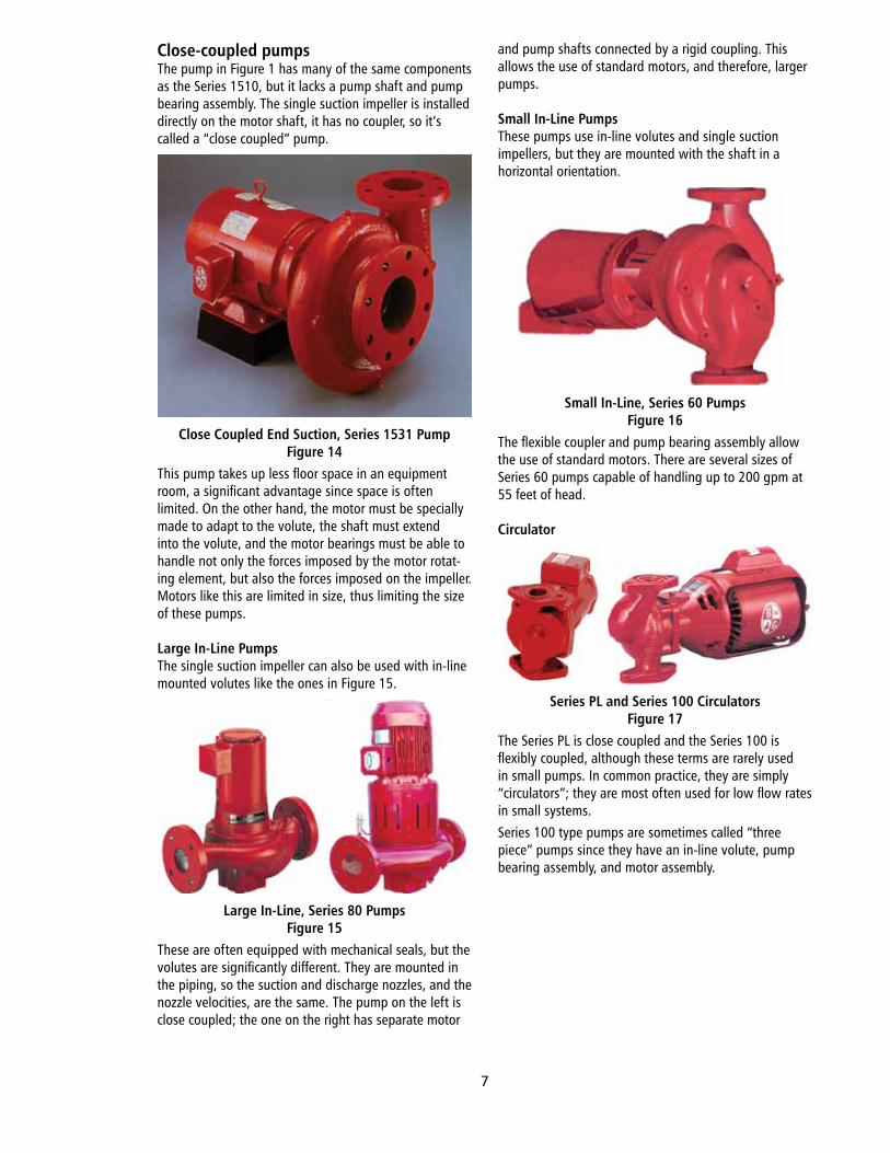
Close-coupled pumpsThe.pump.in.Figure.1.has.many.of.the.same.components.as.the.Series.1510,.but.it.lacks.a.pump.shaft.and.pump.bearing.assembly..The.single.suction.impeller.is.installed.directly.on.the.motor.shaft,.it.has.no.coupler,.so.it’s.called.a.“close.coupled”.pump.
Close Coupled End Suction, Series 1531 PumpFigure 14
This.pump.takes.up.less.floor.space.in.an.equipment.room,.a.significant.advantage.since.space.is.often.limited..On.the.other.hand,.the.motor.must.be.specially.made.to.adapt.to.the.volute,.the.shaft.must.extend.into.the.volute,.and.the.motor.bearings.must.be.able.to.handle.not.only.the.forces.imposed.by.the.motor.rotat-ing.element,.but.also.the.forces.imposed.on.the.impeller..Motors.like.this.are.limited.in.size,.thus.limiting.the.size.of.these.pumps.
Large In-Line PumpsThe.single.suction.impeller.can.also.be.used.with.in-line.mounted.volutes.like.the.ones.in.Figure.15.
Large In-Line, Series 80 PumpsFigure 15
These.are.often.equipped.with.mechanical.seals,.but.the.volutes.are.significantly.different..They.are.mounted.in.the.piping,.so.the.suction.and.discharge.nozzles,.and.the.nozzle.velocities,.are.the.same..The.pump.on.the.left.is.close.coupled;.the.one.on.the.right.has.separate.motor.
and.pump.shafts.connected.by.a.rigid.coupling..This.allows.the.use.of.standard.motors,.and.therefore,.larger.pumps.
Small In-Line PumpsThese.pumps.use.in-line.volutes.and.single.suction.impellers,.but.they.are.mounted.with.the.shaft.in.a.horizontal.orientation.
Small In-Line, Series 60 PumpsFigure 16
The.flexible.coupler.and.pump.bearing.assembly.allow.the.use.of.standard.motors..There.are.several.sizes.of.Series.60.pumps.capable.of.handling.up.to.200.gpm.at.55.feet.of.head.
Circulator
Series PL and Series 100 CirculatorsFigure 17
The.Series.PL.is.close.coupled.and.the.Series.100.is.flexibly.coupled,.although.these.terms.are.rarely.used.in.small.pumps..In.common.practice,.they.are.simply.“circulators”;.they.are.most.often.used.for.low.flow.rates.in.small.systems..Series.100.type.pumps.are.sometimes.called.“three.piece”.pumps.since.they.have.an.in-line.volute,.pump.bearing.assembly,.and.motor.assembly..
7
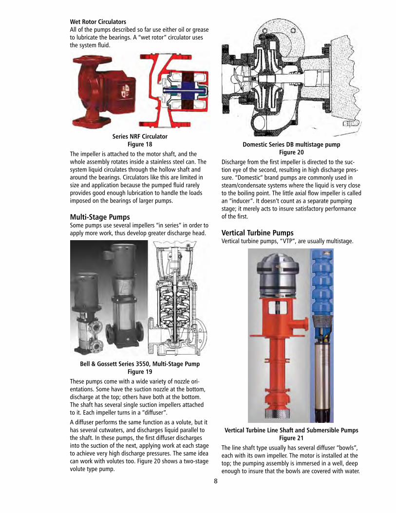
Wet Rotor CirculatorsAll.of.the.pumps.described.so.far.use.either.oil.or.grease.to.lubricate.the.bearings..A.“wet.rotor”.circulator.uses.the.system.fluid.
Series NRF CirculatorFigure 18
The.impeller.is.attached.to.the.motor.shaft,.and.the.whole.assembly.rotates.inside.a.stainless.steel.can..The.system.liquid.circulates.through.the.hollow.shaft.and.around.the.bearings..Circulators.like.this.are.limited.in.size.and.application.because.the.pumped.fluid.rarely.provides.good.enough.lubrication.to.handle.the.loads.imposed.on.the.bearings.of.larger.pumps.
Multi-Stage PumpsSome.pumps.use.several.impellers.“in.series”.in.order.to.apply.more.work,.thus.develop.greater.discharge.head.
Bell & Gossett Series 3550, Multi-Stage PumpFigure 19
These.pumps.come.with.a.wide.variety.of.nozzle.ori-entations..Some.have.the.suction.nozzle.at.the.bottom,.discharge.at.the.top;.others.have.both.at.the.bottom..The.shaft.has.several.single.suction.impellers.attached.to.it..Each.impeller.turns.in.a.“diffuser”.A.diffuser.performs.the.same.function.as.a.volute,.but.it.has.several.cutwaters,.and.discharges.liquid.parallel.to.the.shaft..In.these.pumps,.the.first.diffuser.discharges.into.the.suction.of.the.next,.applying.work.at.each.stage.to.achieve.very.high.discharge.pressures..The.same.idea.can.work.with.volutes.too..Figure.20.shows.a.two-stage.volute.type.pump.
Domestic Series DB multistage pumpFigure 20
Discharge.from.the.first.impeller.is.directed.to.the.suc-tion.eye.of.the.second,.resulting.in.high.discharge.pres-sure..“Domestic”.brand.pumps.are.commonly.used.in.steam/condensate.systems.where.the.liquid.is.very.close.to.the.boiling.point..The.little.axial.flow.impeller.is.called.an.“inducer”..It.doesn’t.count.as.a.separate.pumping.stage;.it.merely.acts.to.insure.satisfactory.performance.of.the.first.
Vertical Turbine PumpsVertical.turbine.pumps,.“VTP”,.are.usually.multistage.
Vertical Turbine Line Shaft and Submersible PumpsFigure 21
The.line.shaft.type.usually.has.several.diffuser.“bowls”,.each.with.its.own.impeller..The.motor.is.installed.at.the.top;.the.pumping.assembly.is.immersed.in.a.well,.deep.enough.to.insure.that.the.bowls.are.covered.with.water..
8
A.sealed.motor.is.used.with.submersible.VTPs,.the.whole.assembly.is.inserted.into.the.well.
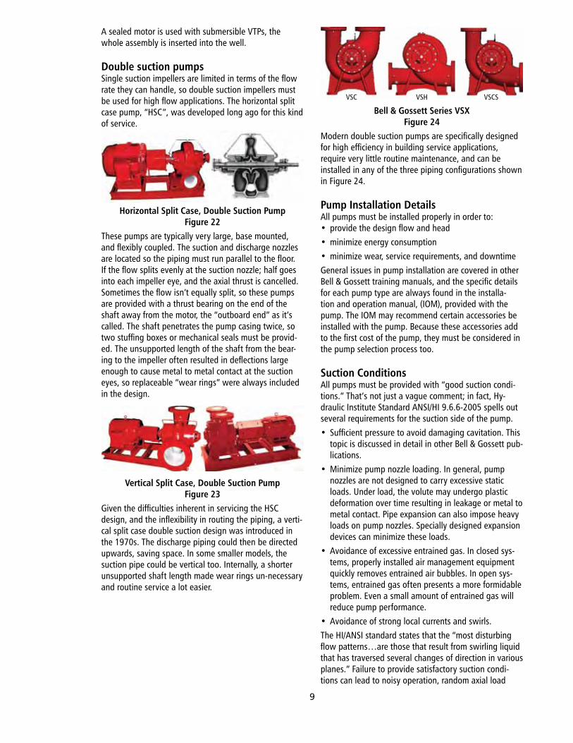
Double suction pumpsSingle.suction.impellers.are.limited.in.terms.of.the.flow.rate.they.can.handle,.so.double.suction.impellers.must.be.used.for.high.flow.applications..The.horizontal.split.case.pump,.“HSC”,.was.developed.long.ago.for.this.kind.of.service.
Horizontal Split Case, Double Suction PumpFigure 22
These.pumps.are.typically.very.large,.base.mounted,.and.flexibly.coupled..The.suction.and.discharge.nozzles.are.located.so.the.piping.must.run.parallel.to.the.floor..If.the.flow.splits.evenly.at.the.suction.nozzle;.half.goes.into.each.impeller.eye,.and.the.axial.thrust.is.cancelled..Sometimes.the.flow.isn’t.equally.split,.so.these.pumps.are.provided.with.a.thrust.bearing.on.the.end.of.the.shaft.away.from.the.motor,.the.“outboard.end”.as.it’s.called..The.shaft.penetrates.the.pump.casing.twice,.so.two.stuffing.boxes.or.mechanical.seals.must.be.provid-ed..The.unsupported.length.of.the.shaft.from.the.bear-ing.to.the.impeller.often.resulted.in.deflections.large.enough.to.cause.metal.to.metal.contact.at.the.suction.eyes,.so.replaceable.“wear.rings”.were.always.included.in.the.design..
Vertical Split Case, Double Suction PumpFigure 23
Given.the.difficulties.inherent.in.servicing.the.HSC.design,.and.the.inflexibility.in.routing.the.piping,.a.verti-cal.split.case.double.suction.design.was.introduced.in.the.1970s..The.discharge.piping.could.then.be.directed.upwards,.saving.space..In.some.smaller.models,.the.suction.pipe.could.be.vertical.too..Internally,.a.shorter.unsupported.shaft.length.made.wear.rings.un-necessary.and.routine.service.a.lot.easier.
Bell & Gossett Series VSXFigure 24
Modern.double.suction.pumps.are.specifically.designed.for.high.efficiency.in.building.service.applications,.require.very.little.routine.maintenance,.and.can.be.installed.in.any.of.the.three.piping.configurations.shown.in.Figure.24.
Pump Installation DetailsAll.pumps.must.be.installed.properly.in.order.to:•. provide.the.design.flow.and.head•. minimize.energy.consumption•. minimize.wear,.service.requirements,.and.downtimeGeneral.issues.in.pump.installation.are.covered.in.other.Bell.&.Gossett.training.manuals,.and.the.specific.details.for.each.pump.type.are.always.found.in.the.installa-tion.and.operation.manual,.(IOM),.provided.with.the.pump..The.IOM.may.recommend.certain.accessories.be.installed.with.the.pump..Because.these.accessories.add.to.the.first.cost.of.the.pump,.they.must.be.considered.in.the.pump.selection.process.too.
Suction ConditionsAll.pumps.must.be.provided.with.“good.suction.condi-tions.”.That’s.not.just.a.vague.comment;.in.fact,.Hy-draulic.Institute.Standard.ANSI/HI.9.6.6-2005.spells.out.several.requirements.for.the.suction.side.of.the.pump.•. Sufficient.pressure.to.avoid.damaging.cavitation..This.
topic.is.discussed.in.detail.in.other.Bell.&.Gossett.pub-lications.
•. Minimize.pump.nozzle.loading..In.general,.pump.nozzles.are.not.designed.to.carry.excessive.static.loads..Under.load,.the.volute.may.undergo.plastic.deformation.over.time.resulting.in.leakage.or.metal.to.metal.contact..Pipe.expansion.can.also.impose.heavy.loads.on.pump.nozzles..Specially.designed.expansion.devices.can.minimize.these.loads.
•. Avoidance.of.excessive.entrained.gas..In.closed.sys-tems,.properly.installed.air.management.equipment.quickly.removes.entrained.air.bubbles..In.open.sys-tems,.entrained.gas.often.presents.a.more.formidable.problem..Even.a.small.amount.of.entrained.gas.will.reduce.pump.performance.
•. Avoidance.of.strong.local.currents.and.swirls.The.HI/ANSI.standard.states.that.the.“most.disturbing.flow.patterns…are.those.that.result.from.swirling.liquid.that.has.traversed.several.changes.of.direction.in.various.planes.”.Failure.to.provide.satisfactory.suction.condi-tions.can.lead.to.noisy.operation,.random.axial.load.
VSC VSH VSCS
9
oscillations,.premature.bearing.or.seal.failure,.or.cavita-tion.damage.to.the.impeller.or.volute..Ideal.suction.conditions.for.clean.water.systems.can.be.provided.by.a.straight.length.of.pipe,.sized.to.avoid.velocities.greater.than.8.ft/s..The.straight.pipe.should.be.at.least.five.pipe.diameters.long,.larger.pumps.may.require.up.to.eight.pipe.diameters.of.straight.length..Short.suction.piping,.represented.by.an.elbow.installed.too.close.to.the.suc-tion.nozzle,.can.result.in.excessive.bearing.loads..
Increased Bearing Loads Caused By Poor Suction Piping
Figure 25In.Figure.25,.the.elbow.on.the.left.is.close.to.the.impel-ler..Inertial.effects.on.the.water.as.it.changes.direction.result.in.large.differences.in.velocity.across.the.suction.eye..“Momentum”.is.a.function.of.mass.and.velocity..The.difference.in.momentum.across.the.suction.eye.exerts.a.torque,.or.turning.action.as.shown.by.the.large.arrows..The.shaft.must.be.short.or.stiff.enough.to.resist.deflection,.but.the.shaft.bearings.will.see.increased.radial.loads.in.any.event..By.increasing.the.length.of.the.suction.pipe,.on.the.right,.velocity.differences.even.out,.reducing.shaft.and.bearing.loads..For.small.end.suction.pumps,.a.length.of.straight.pipe.at.the.suction.nozzle.is.not.likely.to.be.a.problem,.but.for.larger.pumps,.it.is.a.major.constraint.in.laying.out.the.equipment.room..Floor.space.in.building.equipment.rooms.is.often.limited,.since.mechanical.spaces.don’t.generate.rent.revenue,.or.contribute.to.the.building’s.esthetic.appeal.
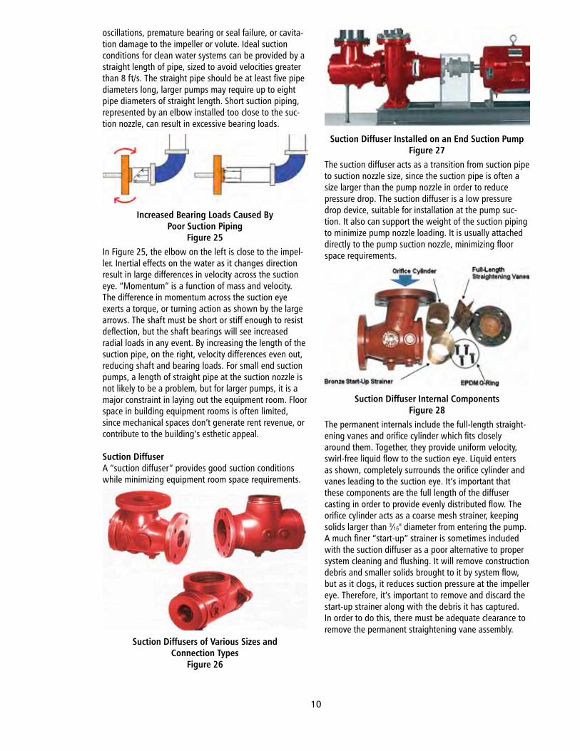
Suction DiffuserA.“suction.diffuser”.provides.good.suction.conditions.while.minimizing.equipment.room.space.requirements.
Suction Diffusers of Various Sizes and Connection Types
Figure 26
Suction Diffuser Installed on an End Suction PumpFigure 27
The.suction.diffuser.acts.as.a.transition.from.suction.pipe.to.suction.nozzle.size,.since.the.suction.pipe.is.often.a.size.larger.than.the.pump.nozzle.in.order.to.reduce..pressure.drop..The.suction.diffuser.is.a.low.pressure.drop.device,.suitable.for.installation.at.the.pump.suc-tion..It.also.can.support.the.weight.of.the.suction.piping.to.minimize.pump.nozzle.loading..It.is.usually.attached.directly.to.the.pump.suction.nozzle,.minimizing.floor.space.requirements.
Suction Diffuser Internal ComponentsFigure 28
The.permanent.internals.include.the.full-length.straight-ening.vanes.and.orifice.cylinder.which.fits.closely.around.them..Together,.they.provide.uniform.velocity,.swirl-free.liquid.flow.to.the.suction.eye..Liquid.enters.as.shown,.completely.surrounds.the.orifice.cylinder.and.vanes.leading.to.the.suction.eye..It’s.important.that.these.components.are.the.full.length.of.the.diffuser.casting.in.order.to.provide.evenly.distributed.flow..The.orifice.cylinder.acts.as.a.coarse.mesh.strainer,.keeping.solids.larger.than.3⁄16".diameter.from.entering.the.pump..A.much.finer.“start-up”.strainer.is.sometimes.included.with.the.suction.diffuser.as.a.poor.alternative.to.proper.system.cleaning.and.flushing..It.will.remove.construction.debris.and.smaller.solids.brought.to.it.by.system.flow,.but.as.it.clogs,.it.reduces.suction.pressure.at.the.impeller.eye..Therefore,.it’s.important.to.remove.and.discard.the.start-up.strainer.along.with.the.debris.it.has.captured..In.order.to.do.this,.there.must.be.adequate.clearance.to.remove.the.permanent.straightening.vane.assembly.
10
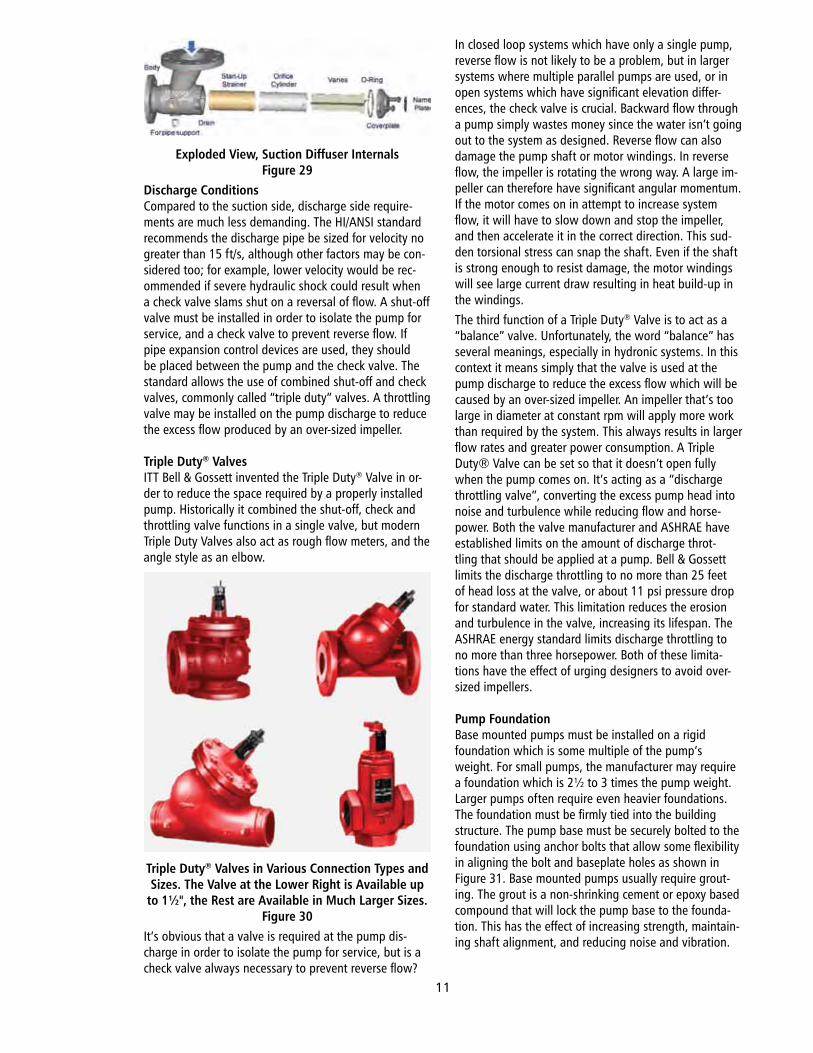
Exploded View, Suction Diffuser InternalsFigure 29
Discharge ConditionsCompared.to.the.suction.side,.discharge.side.require-ments.are.much.less.demanding..The.HI/ANSI.standard.recommends.the.discharge.pipe.be.sized.for.velocity.no.greater.than.15.ft/s,.although.other.factors.may.be.con-sidered.too;.for.example,.lower.velocity.would.be.rec-ommended.if.severe.hydraulic.shock.could.result.when.a.check.valve.slams.shut.on.a.reversal.of.flow..A.shut-off.valve.must.be.installed.in.order.to.isolate.the.pump.for.service,.and.a.check.valve.to.prevent.reverse.flow..If.pipe.expansion.control.devices.are.used,.they.should.be.placed.between.the.pump.and.the.check.valve..The.standard.allows.the.use.of.combined.shut-off.and.check.valves,.commonly.called.“triple.duty”.valves..A.throttling.valve.may.be.installed.on.the.pump.discharge.to.reduce.the.excess.flow.produced.by.an.over-sized.impeller.
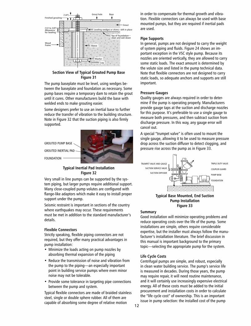
Triple Duty® ValvesITT.Bell.&.Gossett.invented.the.Triple.Duty®.Valve.in.or-der.to.reduce.the.space.required.by.a.properly.installed.pump..Historically.it.combined.the.shut-off,.check.and.throttling.valve.functions.in.a.single.valve,.but.modern.Triple.Duty.Valves.also.act.as.rough.flow.meters,.and.the.angle.style.as.an.elbow.
Triple Duty® Valves in Various Connection Types and Sizes. The Valve at the Lower Right is Available up
to 1½", the Rest are Available in Much Larger Sizes.Figure 30
It’s.obvious.that.a.valve.is.required.at.the.pump.dis-charge.in.order.to.isolate.the.pump.for.service,.but.is.a.check.valve.always.necessary.to.prevent.reverse.flow?.
In.closed.loop.systems.which.have.only.a.single.pump,.reverse.flow.is.not.likely.to.be.a.problem,.but.in.larger.systems.where.multiple.parallel.pumps.are.used,.or.in.open.systems.which.have.significant.elevation.differ-ences,.the.check.valve.is.crucial..Backward.flow.through.a.pump.simply.wastes.money.since.the.water.isn’t.going.out.to.the.system.as.designed..Reverse.flow.can.also.damage.the.pump.shaft.or.motor.windings..In.reverse.flow,.the.impeller.is.rotating.the.wrong.way..A.large.im-peller.can.therefore.have.significant.angular.momentum..If.the.motor.comes.on.in.attempt.to.increase.system.flow,.it.will.have.to.slow.down.and.stop.the.impeller,.and.then.accelerate.it.in.the.correct.direction..This.sud-den.torsional.stress.can.snap.the.shaft..Even.if.the.shaft.is.strong.enough.to.resist.damage,.the.motor.windings.will.see.large.current.draw.resulting.in.heat.build-up.in.the.windings.The.third.function.of.a.Triple.Duty®.Valve.is.to.act.as.a.“balance”.valve..Unfortunately,.the.word.“balance”.has.several.meanings,.especially.in.hydronic.systems..In.this.context.it.means.simply.that.the.valve.is.used.at.the.pump.discharge.to.reduce.the.excess.flow.which.will.be.caused.by.an.over-sized.impeller..An.impeller.that’s.too.large.in.diameter.at.constant.rpm.will.apply.more.work.than.required.by.the.system..This.always.results.in.larger.flow.rates.and.greater.power.consumption..A.Triple.Duty®.Valve.can.be.set.so.that.it.doesn’t.open.fully.when.the.pump.comes.on..It’s.acting.as.a.“discharge.throttling.valve”,.converting.the.excess.pump.head.into.noise.and.turbulence.while.reducing.flow.and.horse-power..Both.the.valve.manufacturer.and.ASHRAE.have.established.limits.on.the.amount.of.discharge.throt-tling.that.should.be.applied.at.a.pump..Bell.&.Gossett.limits.the.discharge.throttling.to.no.more.than.25.feet.of.head.loss.at.the.valve,.or.about.11.psi.pressure.drop.for.standard.water..This.limitation.reduces.the.erosion.and.turbulence.in.the.valve,.increasing.its.lifespan..The.ASHRAE.energy.standard.limits.discharge.throttling.to.no.more.than.three.horsepower..Both.of.these.limita-tions.have.the.effect.of.urging.designers.to.avoid.over-sized.impellers.
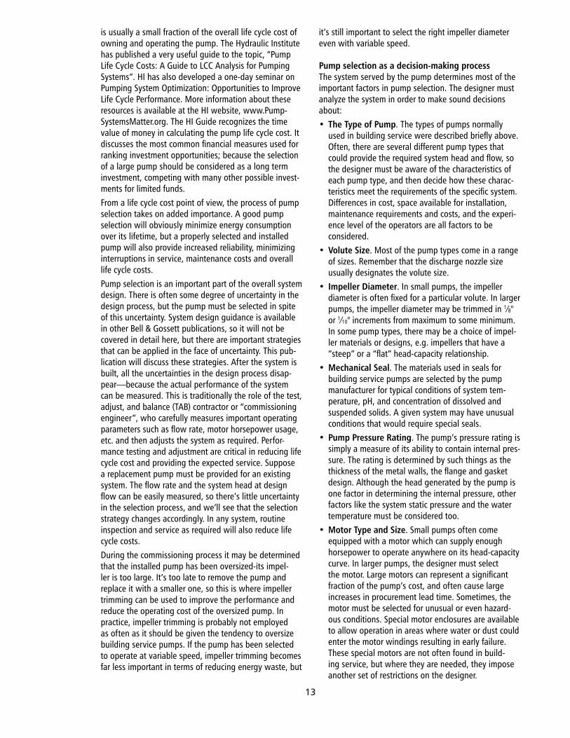
Pump FoundationBase.mounted.pumps.must.be.installed.on.a.rigid.foundation.which.is.some.multiple.of.the.pump’s.weight..For.small.pumps,.the.manufacturer.may.require.a.foundation.which.is.2½.to.3.times.the.pump.weight..Larger.pumps.often.require.even.heavier.foundations..The.foundation.must.be.firmly.tied.into.the.building.structure..The.pump.base.must.be.securely.bolted.to.the.foundation.using.anchor.bolts.that.allow.some.flexibility.in.aligning.the.bolt.and.baseplate.holes.as.shown.in.Figure.31..Base.mounted.pumps.usually.require.grout-ing..The.grout.is.a.non-shrinking.cement.or.epoxy.based.compound.that.will.lock.the.pump.base.to.the.founda-tion..This.has.the.effect.of.increasing.strength,.maintain-ing.shaft.alignment,.and.reducing.noise.and.vibration.
11
Section View of Typical Grouted Pump BaseFigure 31
The.pump.baseplate.must.be.level,.using.wedges.be-tween.the.baseplate.and.foundation.as.necessary..Some.pump.bases.require.a.temporary.dam.to.retain.the.grout.until.it.cures..Other.manufacturers.build.the.base.with.welded.ends.to.make.grouting.easier.Some.designers.prefer.to.use.an.inertial.base.to.further.reduce.the.transfer.of.vibration.to.the.building.structure..Note.in.Figure.32.that.the.suction.piping.is.also.firmly.supported.
Typical Inertial Pad InstallationFigure 32
Very.small.in.line.pumps.can.be.supported.by.the.sys-tem.piping,.but.larger.pumps.require.additional.support..Many.close-coupled.pump.volutes.are.configured.with.flange-like.adaptors.which.make.it.easy.to.install.proper.support.under.the.pump..Seismic.restraint.is.important.in.sections.of.the.country.where.earthquakes.may.occur..These.requirements.must.be.met.in.addition.to.the.standard.manufacturer’s.details.
Flexible ConnectorsStrictly.speaking,.flexible.piping.connectors.are.not.required,.but.they.offer.many.practical.advantages.in.pump.installation:•. Minimize.the.loads.acting.on.pump.nozzles.by..
absorbing.thermal.expansion.of.the.piping•. Reduce.the.transmission.of.noise.and.vibration.from.
the.pump.to.the.piping—an.especially.important.point.in.building.service.pumps.where.even.minor.noise.may.not.be.tolerable.
•. Provide.some.tolerance.in.targeting.pipe.connections.between.the.pump.and.system.
Typical.flexible.connectors.are.made.of.braided.stainless.steel,.single.or.double.sphere.rubber..All.of.them.are.capable.of.absorbing.some.degree.of.relative.motion.
in.order.to.compensate.for.thermal.growth.and.vibra-tion..Flexible.connectors.can.always.be.used.with.base.mounted.pumps,.but.they.are.required.if.inertial.pads.are.used.
Pipe SupportsIn.general,.pumps.are.not.designed.to.carry.the.weight.of.system.piping.and.fluids..Figure.24.shows.an.im-portant.exception.in.the.VSC.style.pump..Because.its.nozzles.are.oriented.vertically,.they.are.allowed.to.carry.some.static.loads..The.exact.amount.is.determined.by.the.volute.size.and.listed.in.the.pump.technical.data..Note.that.flexible.connectors.are.not.designed.to.carry.static.loads,.so.adequate.anchors.and.supports.are.still.important.
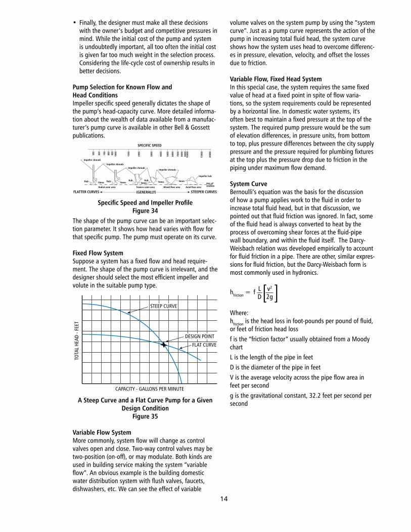
Pressure GaugesQuality.gauges.are.always.required.in.order.to.deter-mine.if.the.pump.is.operating.properly..Manufacturers.provide.gauge.taps.at.the.suction.and.discharge.nozzles.for.this.purpose..It’s.preferable.to.use.a.single.gauge.to.measure.both.pressures,.and.then.subtract.suction.from.discharge.pressure..In.this.way,.any.gauge.error.will.cancel.out.A.special.“trumpet.valve”.is.often.used.to.mount.the.single.gauge,.allowing.it.to.be.used.to.measure.pressure.drop.across.the.suction.diffuser.to.detect.clogging,.and.pressure.rise.across.the.pump.as.in.Figure.33.
Typical Base Mounted, End Suction Pump Installation
Figure 33SummaryGood.installation.will.minimize.operating.problems.and.reduce.operating.costs.over.the.life.of.the.pump..Some.installations.are.simple,.others.require.considerable.expertise,.but.the.installer.must.always.follow.the.manu-facturer’s.installation.literature..The.brief.discussion.in.this.manual.is.important.background.to.the.primary.topic—selecting.the.appropriate.pump.for.the.system.
Life Cycle CostsCentrifugal.pumps.are.simple,.and.robust,.especially.in.clean.water.building.service..The.pump’s.service.life.is.measured.in.decades..During.those.years,.the.pump.may.require.repair,.it.will.need.routine.maintenance,.and.it.will.certainly.use.increasingly.expensive.electrical.energy..All.of.these.costs.must.be.added.to.the.initial.procurement.and.installation.costs.in.order.to.calculate.the.“life.cycle.cost”.of.ownership..This.is.an.important.issue.in.pump.selection:.the.installed.cost.of.the.pump.
Finished grouting(1/4") Grout hole Base
Leveling wedges or shims—left in place
Top of foundation—clean and wet down
Sleeve
Washer
Lug
(1/2 to 3/4")Allowancefor leveling
Woodframe
Grout
TRUMPET VALVE AND GAUGE
SUCTION SERVICE VALVE
SUCTION DIFFUSER
TRIPLE DUTY VALVE
COUPLER GUARD
PUMP BASE
FOUNDATION
GROUTED.PUMP.BASE
GROUTED.INERTIAL.PAD
FOUNDATION
12
is.usually.a.small.fraction.of.the.overall.life.cycle.cost.of.owning.and.operating.the.pump..The.Hydraulic.Institute.has.published.a.very.useful.guide.to.the.topic,.“Pump.Life.Cycle.Costs:.A.Guide.to.LCC.Analysis.for.Pumping.Systems”..HI.has.also.developed.a.one-day.seminar.on.Pumping.System.Optimization:.Opportunities.to.Improve.Life.Cycle.Performance..More.information.about.these.resources.is.available.at.the.HI.website,.www.Pump-SystemsMatter.org..The.HI.Guide.recognizes.the.time.value.of.money.in.calculating.the.pump.life.cycle.cost..It.discusses.the.most.common.financial.measures.used.for.ranking.investment.opportunities;.because.the.selection.of.a.large.pump.should.be.considered.as.a.long.term.investment,.competing.with.many.other.possible.invest-ments.for.limited.funds.From.a.life.cycle.cost.point.of.view,.the.process.of.pump.selection.takes.on.added.importance..A.good.pump.selection.will.obviously.minimize.energy.consumption.over.its.lifetime,.but.a.properly.selected.and.installed.pump.will.also.provide.increased.reliability,.minimizing.interruptions.in.service,.maintenance.costs.and.overall.life.cycle.costs.Pump.selection.is.an.important.part.of.the.overall.system.design..There.is.often.some.degree.of.uncertainty.in.the.design.process,.but.the.pump.must.be.selected.in.spite.of.this.uncertainty..System.design.guidance.is.available.in.other.Bell.&.Gossett.publications,.so.it.will.not.be.covered.in.detail.here,.but.there.are.important.strategies.that.can.be.applied.in.the.face.of.uncertainty..This.pub-lication.will.discuss.these.strategies..After.the.system.is.built,.all.the.uncertainties.in.the.design.process.disap-pear—because.the.actual.performance.of.the.system.can.be.measured..This.is.traditionally.the.role.of.the.test,.adjust,.and.balance.(TAB).contractor.or.“commissioning.engineer”,.who.carefully.measures.important.operating.parameters.such.as.flow.rate,.motor.horsepower.usage,.etc..and.then.adjusts.the.system.as.required..Perfor-mance.testing.and.adjustment.are.critical.in.reducing.life.cycle.cost.and.providing.the.expected.service..Suppose.a.replacement.pump.must.be.provided.for.an.existing.system..The.flow.rate.and.the.system.head.at.design.flow.can.be.easily.measured,.so.there’s.little.uncertainty.in.the.selection.process,.and.we’ll.see.that.the.selection.strategy.changes.accordingly..In.any.system,.routine.inspection.and.service.as.required.will.also.reduce.life.cycle.costs.During.the.commissioning.process.it.may.be.determined.that.the.installed.pump.has.been.oversized-its.impel-ler.is.too.large..It’s.too.late.to.remove.the.pump.and.replace.it.with.a.smaller.one,.so.this.is.where.impeller.trimming.can.be.used.to.improve.the.performance.and.reduce.the.operating.cost.of.the.oversized.pump..In.practice,.impeller.trimming.is.probably.not.employed.as.often.as.it.should.be.given.the.tendency.to.oversize.building.service.pumps..If.the.pump.has.been.selected.to.operate.at.variable.speed,.impeller.trimming.becomes.far.less.important.in.terms.of.reducing.energy.waste,.but.
it’s.still.important.to.select.the.right.impeller.diameter.even.with.variable.speed.
Pump selection as a decision-making processThe.system.served.by.the.pump.determines.most.of.the.important.factors.in.pump.selection..The.designer.must.analyze.the.system.in.order.to.make.sound.decisions.about:•. The Type of Pump..The.types.of.pumps.normally.
used.in.building.service.were.described.briefly.above..Often,.there.are.several.different.pump.types.that.could.provide.the.required.system.head.and.flow,.so.the.designer.must.be.aware.of.the.characteristics.of.each.pump.type,.and.then.decide.how.these.charac-teristics.meet.the.requirements.of.the.specific.system..Differences.in.cost,.space.available.for.installation,.maintenance.requirements.and.costs,.and.the.experi-ence.level.of.the.operators.are.all.factors.to.be..considered.
•. Volute Size..Most.of.the.pump.types.come.in.a.range.of.sizes..Remember.that.the.discharge.nozzle.size.usually.designates.the.volute.size.
•. Impeller Diameter..In.small.pumps,.the.impeller.diameter.is.often.fixed.for.a.particular.volute..In.larger.pumps,.the.impeller.diameter.may.be.trimmed.in.1⁄8".or.1⁄10".increments.from.maximum.to.some.minimum..In.some.pump.types,.there.may.be.a.choice.of.impel-ler.materials.or.designs,.e.g..impellers.that.have.a.“steep”.or.a.“flat”.head-capacity.relationship.
•. Mechanical Seal..The.materials.used.in.seals.for.building.service.pumps.are.selected.by.the.pump.manufacturer.for.typical.conditions.of.system.tem-perature,.pH,.and.concentration.of.dissolved.and.suspended.solids..A.given.system.may.have.unusual.conditions.that.would.require.special.seals.
•. Pump Pressure Rating..The.pump’s.pressure.rating.is.simply.a.measure.of.its.ability.to.contain.internal.pres-sure..The.rating.is.determined.by.such.things.as.the.thickness.of.the.metal.walls,.the.flange.and.gasket.design..Although.the.head.generated.by.the.pump.is.one.factor.in.determining.the.internal.pressure,.other.factors.like.the.system.static.pressure.and.the.water.temperature.must.be.considered.too.
•. Motor Type and Size..Small.pumps.often.come.equipped.with.a.motor.which.can.supply.enough.horsepower.to.operate.anywhere.on.its.head-capacity.curve..In.larger.pumps,.the.designer.must.select.the.motor..Large.motors.can.represent.a.significant.fraction.of.the.pump’s.cost,.and.often.cause.large.increases.in.procurement.lead.time..Sometimes,.the.motor.must.be.selected.for.unusual.or.even.hazard-ous.conditions..Special.motor.enclosures.are.available.to.allow.operation.in.areas.where.water.or.dust.could.enter.the.motor.windings.resulting.in.early.failure..These.special.motors.are.not.often.found.in.build-ing.service,.but.where.they.are.needed,.they.impose.another.set.of.restrictions.on.the.designer.
13
•. Finally,.the.designer.must.make.all.these.decisions.with.the.owner’s.budget.and.competitive.pressures.in.mind..While.the.initial.cost.of.the.pump.and.system.is.undoubtedly.important,.all.too.often.the.initial.cost.is.given.far.too.much.weight.in.the.selection.process..Considering.the.life-cycle.cost.of.ownership.results.in.better.decisions.
Pump Selection for Known Flow and Head ConditionsImpeller.specific.speed.generally.dictates.the.shape.of.the.pump’s.head-capacity.curve..More.detailed.informa-tion.about.the.wealth.of.data.available.from.a.manufac-turer’s.pump.curve.is.available.in.other.Bell.&.Gossett.publications.
Specific Speed and Impeller ProfileFigure 34
The.shape.of.the.pump.curve.can.be.an.important.selec-tion.parameter..It.shows.how.head.varies.with.flow.for.that.specific.pump..The.pump.must.operate.on.its.curve.
Fixed Flow SystemSuppose.a.system.has.a.fixed.flow.and.head.require-ment..The.shape.of.the.pump.curve.is.irrelevant,.and.the.designer.should.select.the.most.efficient.impeller.and.volute.in.the.suitable.pump.type.
A Steep Curve and a Flat Curve Pump for a Given Design Condition
Figure 35
Variable Flow SystemMore.commonly,.system.flow.will.change.as.control.valves.open.and.close..Two-way.control.valves.may.be.two-position.(on-off),.or.may.modulate..Both.kinds.are.used.in.building.service.making.the.system.“variable.flow”..An.obvious.example.is.the.building.domestic..water.distribution.system.with.flush.valves,.faucets,.dishwashers,.etc..We.can.see.the.effect.of.variable.
volume.valves.on.the.system.pump.by.using.the.“system.curve”..Just.as.a.pump.curve.represents.the.action.of.the.pump.in.increasing.total.fluid.head,.the.system.curve.shows.how.the.system.uses.head.to.overcome.differenc-es.in.pressure,.elevation,.velocity,.and.offset.the.losses.due.to.friction.
Variable Flow, Fixed Head SystemIn.this.special.case,.the.system.requires.the.same.fixed.value.of.head.at.a.fixed.point.in.spite.of.flow.varia-tions,.so.the.system.requirements.could.be.represented.by.a.horizontal.line..In.domestic.water.systems,.it's.often.best.to.maintain.a.fixed.pressure.at.the.top.of.the.system..The.required.pump.pressure.would.be.the.sum.of.elevation.differences,.in.pressure.units,.from.bottom.to.top,.plus.pressure.differences.between.the.city.supply.pressure.and.the.pressure.required.for.plumbing.fixtures.at.the.top.plus.the.pressure.drop.due.to.friction.in.the.piping.under.maximum.flow.demand.
System CurveBernoulli’s.equation.was.the.basis.for.the.discussion.of.how.a.pump.applies.work.to.the.fluid.in.order.to.increase.total.fluid.head,.but.in.that.discussion,.we.pointed.out.that.fluid.friction.was.ignored..In.fact,.some.of.the.fluid.head.is.always.converted.to.heat.by.the.process.of.overcoming.shear.forces.at.the.fluid-pipe.wall.boundary,.and.within.the.fluid.itself...The.Darcy-Weisbach.relation.was.developed.empirically.to.account.for.fluid.friction.in.a.pipe..There.are.other,.similar.expres-sions.for.fluid.friction,.but.the.Darcy-Weisbach.form.is.most.commonly.used.in.hydronics.
hfriction.=. f. L. v2
. . D. 2g
Where:hfriction.is.the.head.loss.in.foot-pounds.per.pound.of.fluid,.or.feet.of.friction.head.lossf.is.the.“friction.factor”.usually.obtained.from.a.Moody.chartL.is.the.length.of.the.pipe.in.feetD.is.the.diameter.of.the.pipe.in.feetV.is.the.average.velocity.across.the.pipe.flow.area.in.feet.per.secondg.is.the.gravitational.constant,.32.2.feet.per.second.per.second
SPECIFIC SPEED
(GENERALLY)FLATTER CURVES STEEPER CURVES
Impeller hub
Impeller shroudsImpeller shrouds
Impeller shrouds
Impeller shrouds
Hub Hub Hub Hub VanesVanesVanesVanesVanes
Radial-vane area Frances-vane area Mixed-flow area Axial-flow areaAxis ofrotation
500
600
700
800
900
1000
1500
2000
3000
4000
5000
6000
7000
8000
9000
1000
0
1500
0
2000
0
STEEP CURVE
DESIGN POINT
FLAT CURVE
TOTA
L HE
AD -
FEET
CAPACITY - GALLONS PER MINUTE
[ ]
14
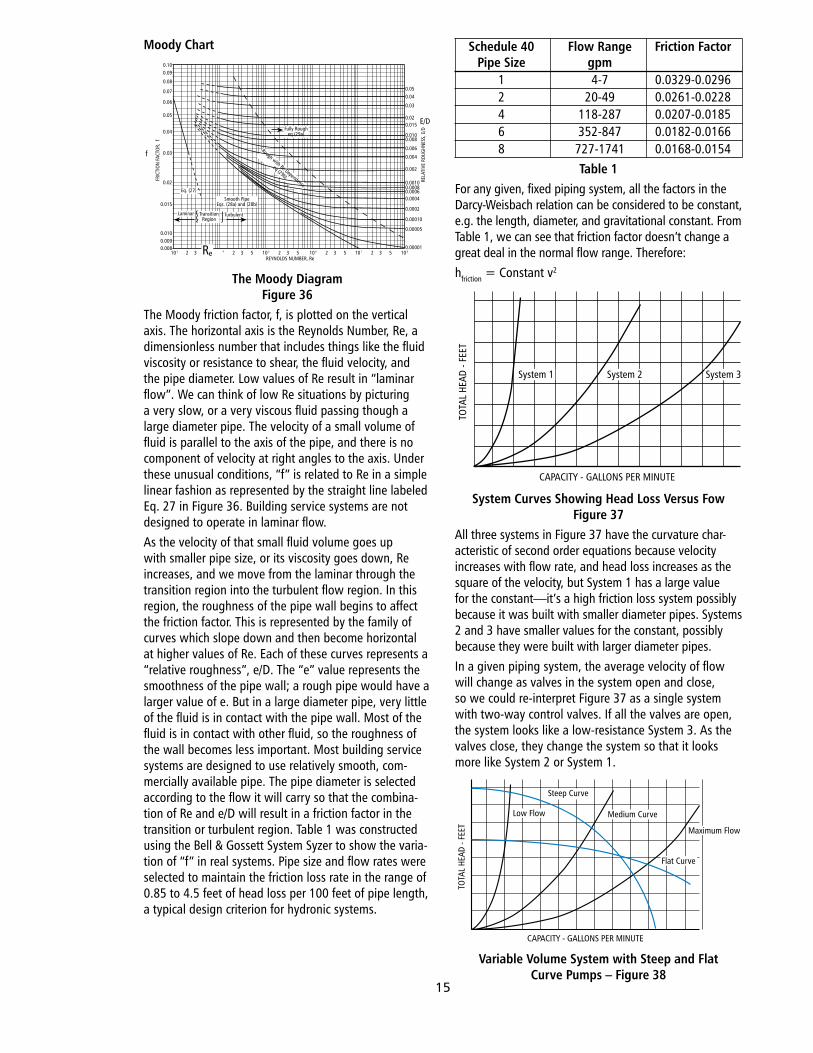
Moody Chart
The Moody DiagramFigure 36
The.Moody.friction.factor,.f,.is.plotted.on.the.vertical.axis..The.horizontal.axis.is.the.Reynolds.Number,.Re,.a.dimensionless.number.that.includes.things.like.the.fluid.viscosity.or.resistance.to.shear,.the.fluid.velocity,.and.the.pipe.diameter..Low.values.of.Re.result.in.“laminar.flow”..We.can.think.of.low.Re.situations.by.picturing.a.very.slow,.or.a.very.viscous.fluid.passing.though.a.large.diameter.pipe..The.velocity.of.a.small.volume.of.fluid.is.parallel.to.the.axis.of.the.pipe,.and.there.is.no.component.of.velocity.at.right.angles.to.the.axis..Under.these.unusual.conditions,.“f”.is.related.to.Re.in.a.simple.linear.fashion.as.represented.by.the.straight.line.labeled.Eq..27.in.Figure.36..Building.service.systems.are.not.designed.to.operate.in.laminar.flow.As.the.velocity.of.that.small.fluid.volume.goes.up.with.smaller.pipe.size,.or.its.viscosity.goes.down,.Re.increases,.and.we.move.from.the.laminar.through.the.transition.region.into.the.turbulent.flow.region..In.this.region,.the.roughness.of.the.pipe.wall.begins.to.affect.the.friction.factor..This.is.represented.by.the.family.of.curves.which.slope.down.and.then.become.horizontal.at.higher.values.of.Re..Each.of.these.curves.represents.a.“relative.roughness”,.e/D..The.“e”.value.represents.the.smoothness.of.the.pipe.wall;.a.rough.pipe.would.have.a.larger.value.of.e..But.in.a.large.diameter.pipe,.very.little.of.the.fluid.is.in.contact.with.the.pipe.wall..Most.of.the.fluid.is.in.contact.with.other.fluid,.so.the.roughness.of.the.wall.becomes.less.important..Most.building.service.systems.are.designed.to.use.relatively.smooth,.com-mercially.available.pipe..The.pipe.diameter.is.selected.according.to.the.flow.it.will.carry.so.that.the.combina-tion.of.Re.and.e/D.will.result.in.a.friction.factor.in.the.transition.or.turbulent.region..Table.1.was.constructed.using.the.Bell.&.Gossett.System.Syzer.to.show.the.varia-tion.of.“f”.in.real.systems..Pipe.size.and.flow.rates.were.selected.to.maintain.the.friction.loss.rate.in.the.range.of.0.85.to.4.5.feet.of.head.loss.per.100.feet.of.pipe.length,.a.typical.design.criterion.for.hydronic.systems.
Schedule 40 Flow Range Friction Factor Pipe Size gpm . 1. 4-7. 0.0329-0.0296. 2. 20-49. 0.0261-0.0228. 4. 118-287. 0.0207-0.0185. 6. 352-847. 0.0182-0.0166. 8. 727-1741. 0.0168-0.0154
Table 1For.any.given,.fixed.piping.system,.all.the.factors.in.the.Darcy-Weisbach.relation.can.be.considered.to.be.constant,.e.g..the.length,.diameter,.and.gravitational.constant..From.Table.1,.we.can.see.that.friction.factor.doesn’t.change.a.great.deal.in.the.normal.flow.range..Therefore:hfriction.=.Constant.v2
System Curves Showing Head Loss Versus FowFigure 37
All.three.systems.in.Figure.37.have.the.curvature.char-acteristic.of.second.order.equations.because.velocity.increases.with.flow.rate,.and.head.loss.increases.as.the.square.of.the.velocity,.but.System.1.has.a.large.value.for.the.constant—it’s.a.high.friction.loss.system.possibly.because.it.was.built.with.smaller.diameter.pipes..Systems.2.and.3.have.smaller.values.for.the.constant,.possibly.because.they.were.built.with.larger.diameter.pipes.In.a.given.piping.system,.the.average.velocity.of.flow.will.change.as.valves.in.the.system.open.and.close,.so.we.could.re-interpret.Figure.37.as.a.single.system.with.two-way.control.valves..If.all.the.valves.are.open,.the.system.looks.like.a.low-resistance.System.3..As.the.valves.close,.they.change.the.system.so.that.it.looks.more.like.System.2.or.System.1.
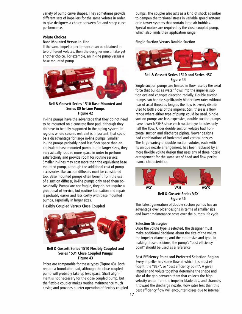
Variable Volume System with Steep and Flat Curve Pumps – Figure 38
REYNOLDS NUMBER, Re10 2 3 43 2 3 5 10 5 2 3 5 10 6 2 3 5 10 7 2 3 5 10 8
0.00001
0.00005
0.00010
0.0002
0.00040.00060.00080.0010
0.002
0.004
0.006
0.0080.010
0.0150.02
0.03
0.040.05
E/D
RELA
TIVE
RO
UGHN
ESS,
E/D
0.0080.0090.010
0.015
0.02
0.03
0.04
0.05
0.06
0.07
0.08
0.090.10
fFR
ICTI
ON
FAC
TOR,
f
Re
Fully Rougheq (29a)
Rough with Re Dependence
eq (29b)
Eq. (27)
Smooth PipeEqs. (28a) and (28b)
TransitionRegion
Laminar Turbulent
TOTA
L HE
AD -
FEET
CAPACITY - GALLONS PER MINUTE
System 1 System 2 System 3
TOTA
L HE
AD -
FEET
CAPACITY - GALLONS PER MINUTE
Low Flow
Steep Curve
Medium Curve
Flat Curve
Maximum Flow
15
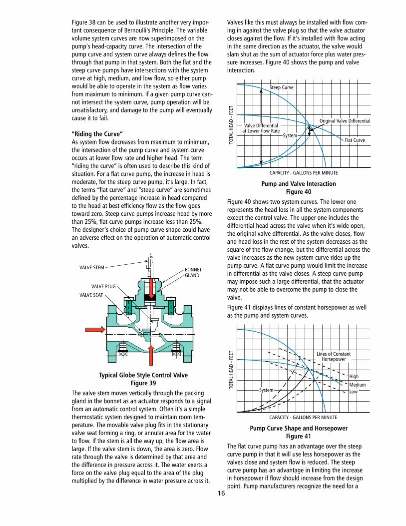
Figure.38.can.be.used.to.illustrate.another.very.impor-tant.consequence.of.Bernoulli’s.Principle..The.variable.volume.system.curves.are.now.superimposed.on.the.pump’s.head-capacity.curve..The.intersection.of.the.pump.curve.and.system.curve.always.defines.the.flow.through.that.pump.in.that.system..Both.the.flat.and.the.steep.curve.pumps.have.intersections.with.the.system.curve.at.high,.medium,.and.low.flow,.so.either.pump.would.be.able.to.operate.in.the.system.as.flow.varies.from.maximum.to.minimum..If.a.given.pump.curve.can-not.intersect.the.system.curve,.pump.operation.will.be.unsatisfactory,.and.damage.to.the.pump.will.eventually.cause.it.to.fail.
“Riding the Curve”As.system.flow.decreases.from.maximum.to.minimum,.the.intersection.of.the.pump.curve.and.system.curve.occurs.at.lower.flow.rate.and.higher.head..The.term.“riding.the.curve”.is.often.used.to.describe.this.kind.of.situation..For.a.flat.curve.pump,.the.increase.in.head.is.moderate,.for.the.steep.curve.pump,.it’s.large..In.fact,.the.terms.“flat.curve”.and.“steep.curve”.are.sometimes.defined.by.the.percentage.increase.in.head.compared.to.the.head.at.best.efficiency.flow.as.the.flow.goes.toward.zero..Steep.curve.pumps.increase.head.by.more.than.25%,.flat.curve.pumps.increase.less.than.25%..The.designer’s.choice.of.pump.curve.shape.could.have.an.adverse.effect.on.the.operation.of.automatic.control.valves.
Typical Globe Style Control ValveFigure 39
The.valve.stem.moves.vertically.through.the.packing.gland.in.the.bonnet.as.an.actuator.responds.to.a.signal.from.an.automatic.control.system..Often.it’s.a.simple.thermostatic.system.designed.to.maintain.room.tem-perature..The.movable.valve.plug.fits.in.the.stationary.valve.seat.forming.a.ring,.or.annular.area.for.the.water.to.flow..If.the.stem.is.all.the.way.up,.the.flow.area.is.large..If.the.valve.stem.is.down,.the.area.is.zero..Flow.rate.through.the.valve.is.determined.by.that.area.and.the.difference.in.pressure.across.it..The.water.exerts.a.force.on.the.valve.plug.equal.to.the.area.of.the.plug.multiplied.by.the.difference.in.water.pressure.across.it..
Valves.like.this.must.always.be.installed.with.flow.com-ing.in.against.the.valve.plug.so.that.the.valve.actuator.closes.against.the.flow..If.it’s.installed.with.flow.acting.in.the.same.direction.as.the.actuator,.the.valve.would.slam.shut.as.the.sum.of.actuator.force.plus.water.pres-sure.increases..Figure.40.shows.the.pump.and.valve.interaction.
Pump and Valve InteractionFigure 40
Figure.40.shows.two.system.curves..The.lower.one.represents.the.head.loss.in.all.the.system.components.except.the.control.valve..The.upper.one.includes.the.differential.head.across.the.valve.when.it’s.wide.open,.the.original.valve.differential..As.the.valve.closes,.flow.and.head.loss.in.the.rest.of.the.system.decreases.as.the.square.of.the.flow.change,.but.the.differential.across.the.valve.increases.as.the.new.system.curve.rides.up.the.pump.curve..A.flat.curve.pump.would.limit.the.increase.in.differential.as.the.valve.closes..A.steep.curve.pump.may.impose.such.a.large.differential,.that.the.actuator.may.not.be.able.to.overcome.the.pump.to.close.the.valve.Figure.41.displays.lines.of.constant.horsepower.as.well.as.the.pump.and.system.curves.
Pump Curve Shape and HorsepowerFigure 41
The.flat.curve.pump.has.an.advantage.over.the.steep.curve.pump.in.that.it.will.use.less.horsepower.as.the.valves.close.and.system.flow.is.reduced..The.steep.curve.pump.has.an.advantage.in.limiting.the.increase.in.horsepower.if.flow.should.increase.from.the.design.point..Pump.manufacturers.recognize.the.need.for.a.
VALVE STEM
VALVE PLUG
VALVE SEAT
BONNETGLAND
TOTA
L HE
AD -
FEET
CAPACITY - GALLONS PER MINUTE
Steep Curve
Original Valve Differential
Flat Curve
Valve Differentialat Lower flow Rate
System
TOTA
L HE
AD -
FEET
CAPACITY - GALLONS PER MINUTE
Lines of ConstantHorsepower
LowSystemMedium
High
16
variety.of.pump.curve.shapes..They.sometimes.provide.different.sets.of.impellers.for.the.same.volutes.in.order.to.give.designers.a.choice.between.flat.and.steep.curve.performance.
Volute ChoicesBase Mounted Versus In-LineIf.the.same.impeller.performance.can.be.obtained.in.two.different.volutes,.then.the.designer.must.make.yet.another.choice..For.example,.an.in-line.pump.versus.a.base.mounted.pump.
Bell & Gossett Series 1510 Base Mounted and Series 80 In-Line Pumps
Figure 42In-line.pumps.have.the.advantage.that.they.do.not.need.to.be.mounted.on.a.concrete.floor.pad,.although.they.do.have.to.be.fully.supported.in.the.piping.system..In.regions.where.seismic.restraint.is.important,.that.could.be.a.disadvantage.for.large.in-line.pumps..Smaller.in-line.pumps.probably.need.less.floor.space.than.an.equivalent.base.mounted.pump,.but.in.larger.sizes,.they.may.actually.require.more.space.in.order.to.perform.satisfactorily.and.provide.room.for.routine.service..Smaller.in-lines.may.cost.more.than.the.equivalent.base.mounted.pump,.although.the.additional.cost.of.pump.accessories.like.suction.diffusers.must.be.considered.too..Base.mounted.pumps.often.benefit.from.the.use.of.a.suction.diffuser,.in-line.pumps.only.need.them.oc-casionally..Pumps.are.not.fragile,.they.do.not.require.a.great.deal.of.service,.but.routine.lubrication.and.repair.is.probably.easier.and.less.costly.with.base.mounted.pumps,.especially.in.larger.sizes.Flexibly Coupled Versus Close Coupled
Bell & Gossett Series 1510 Flexibly Coupled and Series 1531 Close Coupled Pumps
Figure 43Prices.are.comparable.for.these.types.(Figure.43)..Both.require.a.foundation.pad,.although.the.close.coupled.pump.will.probably.take.up.less.space..Shaft.align-ment.is.not.necessary.for.the.close.coupled.pump,.but.the.flexible.coupler.makes.routine.maintenance.much.easier,.and.provides.quieter.operation.of.flexibly.coupled.
pumps..The.coupler.also.acts.as.a.kind.of.shock.absorber.to.dampen.the.torsional.stress.in.variable.speed.systems.or.in.tower.systems.that.contain.large.air.bubbles..Special.motors.are.required.by.the.close.coupled.pump,.which.also.limits.their.application.range..
Single Suction Versus Double Suction
Bell & Gossett Series 1510 and Series HSCFigure 44
Single.suction.pumps.are.limited.in.flow.rate.by.the.axial.force.that.builds.as.water.flows.into.the.impeller.suc-tion.eye.and.changes.direction.radially..Double.suction.pumps.can.handle.significantly.higher.flow.rates.without.fear.of.axial.thrust.as.long.as.the.flow.is.evenly.distrib-uted.to.both.sides.of.the.impeller..Still,.there.is.a.flow.range.where.either.type.of.pump.could.be.used..Single.suction.pumps.are.less.expensive,.double.suction.pumps.have.lower.NPSHR.since.each.suction.eye.handles.only.half.the.flow..Older.double.suction.volutes.had.hori-zontal.suction.and.discharge.piping..Newer.designs.had.combinations.of.horizontal.and.vertical.nozzles..The.large.variety.of.double.suction.volutes,.each.with.its.unique.nozzle.arrangement,.has.been.replaced.by.a.more.flexible.volute.design.that.uses.any.of.three.nozzle.arrangement.for.the.same.set.of.head.and.flow.perfor-mance.characteristics.
VSC VSH VSCSBell & Gossett Series VSX
Figure 45This.latest.generation.of.double.suction.pumps.has.an.advantage.over.older.designs.in.terms.of.smaller.size.and.lower.maintenance.costs.over.the.pump’s.life.cycle.
Selection StrategiesOnce.the.volute.type.is.selected,.the.designer.must.make.additional.decisions.about.the.size.of.the.volute,.the.impeller.diameter,.and.the.motor.size.and.type..In.making.these.decisions,.the.pump’s.“best.efficiency.point”.should.be.used.as.a.reference
Best Efficiency Point and Preferred Selection RegionEvery.impeller.has.some.flow.at.which.it.is.most.ef-ficient,.the.“BEP”,.or.“best.efficiency.point”..A.given.impeller.and.volute.together.determine.the.shape.and.size.of.the.gap.between.them.that.collects.the.high.velocity.water.from.the.impeller.blade.tips,.and.channels.it.toward.the.discharge.nozzle..Flow.rates.less.than.this.best.efficiency.flow.will.encounter.losses.due.to.internal.
17
recirculation,.flow.rates.greater.than.best.efficiency.will.encounter.higher.friction.loss..Typical.centrifugal.pumps.have.a.range.of.flow.rates.where.the.sum.of.friction.and.recirculation.losses.is.at.a.minimum..This.range.is.not.centered.on.the.best.efficiency.flow,.but.is.offset.to.the.left.of.best.efficiency..The.2008.ASHRAE.Handbook,.HVAC.Systems.and.Equipment,.Chapter.43.illustrates.this.low.loss.area.and.the.preferred.selection.region.
Preferred Selection RegionsFigure 46
Pumps.that.operate.in.the.preferred.selection.region.will.be.more.efficient,.and.will.encounter.fewer.maintenance.problems.over.their.life.cycle.compared.to.pumps.that.operate.for.long.periods.outside.of.that.region.
Radial Forces Increase Away From BEPFigure 47
Pumps.are.not.fragile;.the.increasing.radial.forces.exerted.on.the.shaft.will.not.necessarily.cause.damage.or.shaft.deflection,.provided.that.the.shaft.is.stiff.and.strong.enough.to.counter.them.
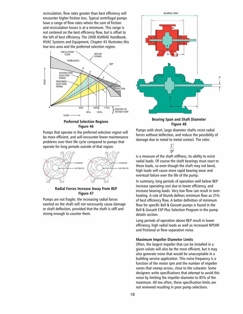
Bearing Span and Shaft DiameterFigure 48
Pumps.with.short,.large.diameter.shafts.resist.radial.forces.without.deflection,.and.reduce.the.possibility.of.damage.due.to.metal.to.metal.contact..The.ratio:
is.a.measure.of.the.shaft.stiffness,.its.ability.to.resist.radial.loads..Of.course.the.shaft.bearings.must.react.to.these.loads,.so.even.though.the.shaft.may.not.bend,.high.loads.will.cause.more.rapid.bearing.wear.and.eventual.failure.over.the.life.of.the.pump.In.summary,.long.periods.of.operation.well.below.BEP.increase.operating.cost.due.to.lower.efficiency,.and.increase.bearing.loads..Very.low.flow.can.result.in.over-heating..A.rule.of.thumb.defines.minimum.flow.as.25%.of.best.efficiency.flow..A.better.definition.of.minimum.flow.for.specific.Bell.&.Gossett.pumps.is.found.in.the.Bell.&.Gossett.ESP.Plus.Selection.Program.in.the.pump.details.section.Long.periods.of.operation.above.BEP.result.in.lower.efficiency,.high.radial.loads.as.well.as.increased.NPSHR.and.frictional.or.flow.separation.noise.
Maximum Impeller Diameter LimitsOften,.the.largest.impeller.that.can.be.installed.in.a.given.volute.will.also.be.the.most.efficient,.but.it.may.also.generate.noise.that.would.be.unacceptable.in.a.building.service.application..This.noise.frequency.is.a.function.of.the.motor.rpm.and.the.number.of.impeller.vanes.that.sweep.across,.close.to.the.cutwater..Some.designers.write.specifications.that.attempt.to.avoid.this.noise.by.limiting.the.impeller.diameter.to.85%.of.the.maximum..All.too.often,.these.specification.limits.are.not.reviewed.resulting.in.poor.pump.selections.
CIRCULATORYFLOW
TURBULENCE
MOTORPOWER
BEP
BD
E
C
SATISFACTORYSELECTIONRANGE
PREFERREDSELECTIONRANGE
FRICTION
A 66%
85%
100% 115%
105%FLOW
HEAD
PERCENT OFDESIGN FLOW}
CUTWATER
SUCTION EYE
CUTWATER
SUCTION EYE
L
D
L
BEARING SPAN
L3
D4
18
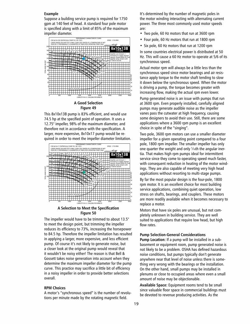
ExampleSuppose.a.building.service.pump.is.required.for.1750.gpm.at.140.feet.of.head..A.standard.four.pole.motor.is.specified.along.with.a.limit.of.85%.of.the.maximum.impeller.diameter..
A Good SelectionFigure 49
This.8x10x13B.pump.is.83%.efficient,.and.would.use.74.5.hp.at.the.specified.point.of.operation..It.uses.a.12.75".impeller,.98%.of.the.maximum.diameter,.and.therefore.not.in.accordance.with.the.specification..A.larger,.more.expensive,.8x10x17.pump.would.be.re-quired.in.order.to.meet.the.impeller.diameter.limitation.
A Selection to Meet the SpecificationFigure 50
The.impeller.would.have.to.be.trimmed.to.about.13.5".to.meet.the.design.point,.but.trimming.the.impeller.reduces.its.efficiency.to.73%,.increasing.the.horsepower.to.84.5.hp..Therefore.the.impeller.limitation.has.resulted.in.applying.a.larger,.more.expensive,.and.less.efficient.pump..Of.course.it’s.not.likely.to.generate.noise,.but.a.closer.look.at.the.original.pump.would.reveal.that.it.wouldn’t.be.noisy.either!.The.reason.is.that.Bell.&.Gossett.takes.noise.generation.into.account.when.they.determine.the.maximum.impeller.diameter.for.the.pump.curve..This.practice.may.sacrifice.a.little.bit.of.efficiency.in.a.noisy.impeller.in.order.to.provide.better.selections.overall.
RPM ChoicesA.motor’s.“synchronous.speed”.is.the.number.of.revolu-tions.per.minute.made.by.the.rotating.magnetic.field..
It’s.determined.by.the.number.of.magnetic.poles.in.the.motor.winding.interacting.with.alternating.current.power..The.three.most.commonly.used.motor.speeds.are:•. Two.pole,.60.Hz.motors.that.run.at.3600.rpm•. Four.pole,.60.Hz.motors.that.run.at.1800.rpm•. Six.pole,.60.Hz.motors.that.run.at.1200.rpmIn.some.countries.electrical.power.is.distributed.at.50.Hz..This.will.cause.a.60.Hz.motor.to.operate.at.5/6.of.its.synchronous.speed.Actual.motor.rpm.will.always.be.a.little.less.than.the.synchronous.speed.since.motor.bearings.and.air.resis-tance.apply.torque.to.the.motor.shaft.tending.to.slow.it.down.below.the.synchronous.speed..When.the.motor.is.driving.a.pump,.the.torque.becomes.greater.with.increasing.flow,.making.the.actual.rpm.even.lower.Pump.generated.noise.is.an.issue.with.pumps.that.run.at.3600.rpm..Even.properly.installed,.carefully.aligned.pumps.may.generate.audible.noise.as.the.impeller.vanes.pass.the.cutwater.at.high.frequency,.causing.some.designers.to.avoid.their.use..Still,.there.are.some.applications.where.a.3600.rpm.pump.is.an.excellent.choice.in.spite.of.the.“singing”.Two.pole,.3600.rpm.motors.can.use.a.smaller.diameter.impeller.for.a.given.operating.point.compared.to.a.four.pole,.1800.rpm.impeller..The.smaller.impeller.has.only.one.quarter.the.weight.and.only.1⁄16th.the.angular.iner-tia..That.makes.high.rpm.pumps.ideal.for.intermittent.service.since.they.come.to.operating.speed.much.faster,.with.consequent.reduction.in.heating.of.the.motor.wind-ings..They.are.also.capable.of.meeting.very.high.head.applications.without.resorting.to.multi-stage.pumps.By.far.the.most.popular.design.is.the.four-pole,.1800.rpm.motor..It.is.an.excellent.choice.for.most.building.service.applications,.combining.quiet.operation,.low.stress.on.shafts,.bearings,.and.couplers..These.motors.are.more.readily.available.when.it.becomes.necessary.to.replace.a.motor.Motors.that.have.six.poles.are.unusual,.but.not.com-pletely.unknown.in.building.service..They.are.well.suited.to.applications.that.require.low.head,.but.high.flow.rates.
Pump Selection-General ConsiderationsPump Location:.If.a.pump.will.be.installed.in.a.sub-basement.or.equipment.room,.pump.generated.noise.is.not.likely.to.be.a.problem..OSHA.has.defined.hazardous.noise.conditions,.but.pumps.typically.don’t.generate.anywhere.near.that.level.of.noise.unless.there.is.some-thing.very.wrong.with.the.bearings.or.the.installation..On.the.other.hand,.small.pumps.may.be.installed.in.plenums.or.close.to.occupied.areas.where.even.a.small.amount.of.noise.may.be.objectionable.Available Space:.Equipment.rooms.tend.to.be.small.since.valuable.floor.space.in.commercial.buildings.must.be.devoted.to.revenue.producing.activities..As.the..
60% 70% 75%80%
83%84% 84.5%
82%
84%83
%82
%80
%
75%
70%
40 HP
50 HP
60 HP
75 HP
100 HP
30 HP
13"
121/2"
12"
111/2"11"101/2"10"
200
180
160
140
120
100
80
60
40
20
0
0 500 1000 1500 2000 2500 3000 3500 40000
10
20
30
NPS
H FE
ET
NPSH REQUIRED
CAPACITY IN U.S. GALLONS PER MINUTE
TOTA
L HE
AD IN
FEE
T
8x10x13B1770 RPM
Impellers are trimmed 1/4"increments to supply requiredcapacity. Responsibility for finalimpeller sizing remains withITT Bell & Gossett.
FOR 8x10x13B CENTRIFUGAL PUMP FIG. NO. VSCSCURVES BASED ON SHOP TEST USING CLEAR COLD WATER AT A TEMPERATURE OF NOTOVER 85•F. PERFORMANCE IS GUARANTEED AT INDICATED OPERATING POINT ONLY.
PERFORMANCE CHARACTERISTIC CURVESPEED 1770 RPM
DATE 9-10-80APPROVED
60% 70% 75%76
%
40 HP50 HP
60 HP75 HP
30 HP
17"
15"
13"
11"
300
100
0
0 500 1000 1500 2000 2500 3000 3500 40000
10
20
30
NPS
H FE
ET
NPSH REQUIRED
CAPACITY IN U.S. GALLONS PER MINUTE
TOTA
L HE
AD IN
FEE
T
8x10x13B1770 RPM
Impellers are trimmed 1/4"increments to supply requiredcapacity. Responsibility for finalimpeller sizing remains withITT Bell & Gossett.
FOR 8x10x17 CENTRIFUGAL PUMP FIG. NO. VSCSCURVES BASED ON SHOP TEST USING CLEAR COLD WATER AT A TEMPERATURE OF NOTOVER 85•F. PERFORMANCE IS GUARANTEED AT INDICATED OPERATING POINT ONLY.
PERFORMANCE CHARACTERISTIC CURVESPEED 1770 RPM
DATE 10-14-78APPROVED
200
16"
14"
12"
10"
100 HP125 HP
150 HP175 HP
50%65% 73%
77%
78%
77%
76%
75%73
%
70%65%
60%
50
40
19
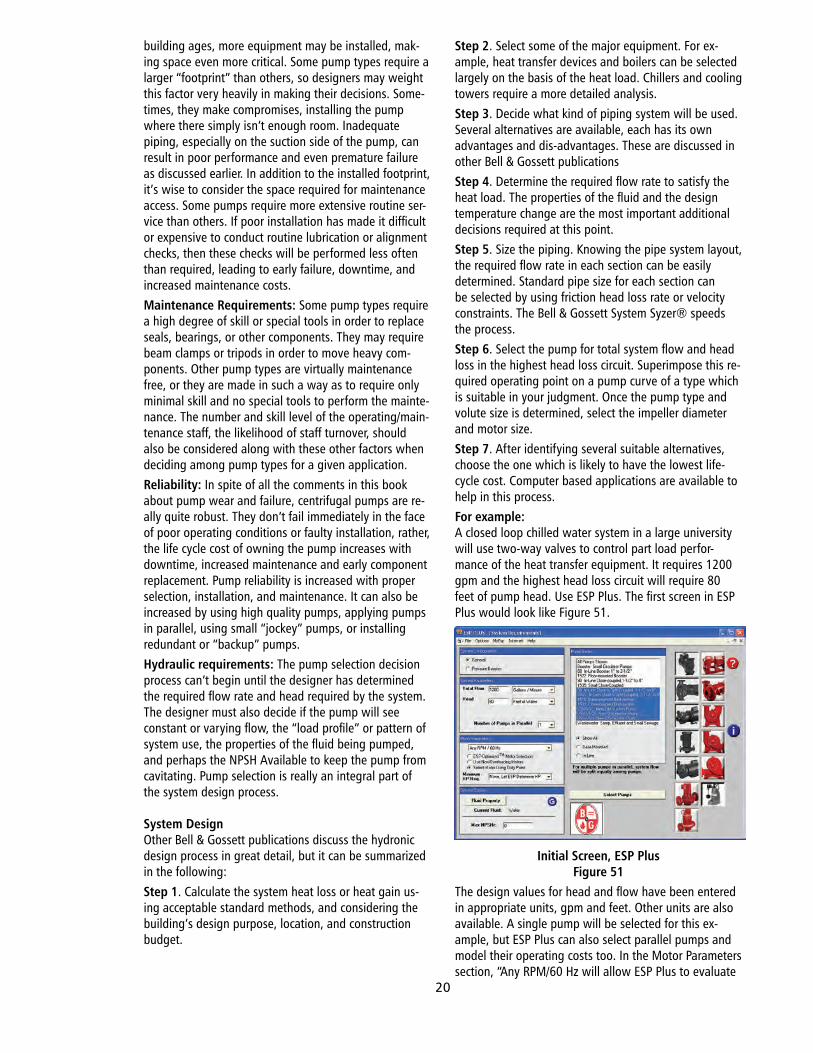
building ages, more equipment may be installed, mak-ing space even more critical. Some pump types require a larger “footprint” than others, so designers may weight this factor very heavily in making their decisions. Some-times, they make compromises, installing the pump where there simply isn’t enough room. Inadequate piping, especially on the suction side of the pump, can result in poor performance and even premature failure as discussed earlier. In addition to the installed footprint, it’s wise to consider the space required for maintenance access. Some pumps require more extensive routine ser-vice than others. If poor installation has made it difficult or expensive to conduct routine lubrication or alignment checks, then these checks will be performed less often than required, leading to early failure, downtime, and increased maintenance costs.Maintenance Requirements: Some pump types require a high degree of skill or special tools in order to replace seals, bearings, or other components. They may require beam clamps or tripods in order to move heavy com-ponents. Other pump types are virtually maintenance free, or they are made in such a way as to require only minimal skill and no special tools to perform the mainte-nance. The number and skill level of the operating/main-tenance staff, the likelihood of staff turnover, should also be considered along with these other factors when deciding among pump types for a given application.Reliability: In spite of all the comments in this book about pump wear and failure, centrifugal pumps are re-ally quite robust. They don’t fail immediately in the face of poor operating conditions or faulty installation, rather, the life cycle cost of owning the pump increases with downtime, increased maintenance and early component replacement. Pump reliability is increased with proper selection, installation, and maintenance. It can also be increased by using high quality pumps, applying pumps in parallel, using small “jockey” pumps, or installing redundant or “backup” pumps.Hydraulic requirements: The pump selection decision process can’t begin until the designer has determined the required flow rate and head required by the system. The designer must also decide if the pump will see constant or varying flow, the “load profile” or pattern of system use, the properties of the fluid being pumped, and perhaps the NPSH Available to keep the pump from cavitating. Pump selection is really an integral part of the system design process.
System DesignOther Bell & Gossett publications discuss the hydronic design process in great detail, but it can be summarized in the following:Step 1. Calculate the system heat loss or heat gain us-ing acceptable standard methods, and considering the building’s design purpose, location, and construction budget.
Step 2. Select some of the major equipment. For ex-ample, heat transfer devices and boilers can be selected largely on the basis of the heat load. Chillers and cooling towers require a more detailed analysis.Step 3. Decide what kind of piping system will be used. Several alternatives are available, each has its own advantages and dis-advantages. These are discussed in other Bell & Gossett publicationsStep 4. Determine the required flow rate to satisfy the heat load. The properties of the fluid and the design temperature change are the most important additional decisions required at this point.Step 5. Size the piping. Knowing the pipe system layout, the required flow rate in each section can be easily determined. Standard pipe size for each section can be selected by using friction head loss rate or velocity constraints. The Bell & Gossett System Syzer® speeds the process.Step 6. Select the pump for total system flow and head loss in the highest head loss circuit. Superimpose this re-quired operating point on a pump curve of a type which is suitable in your judgment. Once the pump type and volute size is determined, select the impeller diameter and motor size.Step 7. After identifying several suitable alternatives, choose the one which is likely to have the lowest life-cycle cost. Computer based applications are available to help in this process.For example:A closed loop chilled water system in a large university will use two-way valves to control part load perfor-mance of the heat transfer equipment. It requires 1200 gpm and the highest head loss circuit will require 80 feet of pump head. Use ESP Plus. The first screen in ESP Plus would look like Figure 51.
Initial Screen, ESP PlusFigure 51
The design values for head and flow have been entered in appropriate units, gpm and feet. Other units are also available. A single pump will be selected for this ex-ample, but ESP Plus can also select parallel pumps and model their operating costs too. In the Motor Parameters section, “Any RPM/60 Hz will allow ESP Plus to evaluate
20
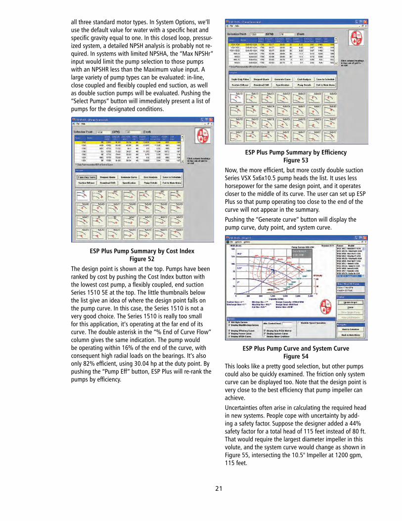
all three standard motor types. In System Options, we’ll use the default value for water with a specific heat and specific gravity equal to one. In this closed loop, pressur-ized system, a detailed NPSH analysis is probably not re-quired. In systems with limited NPSHA, the “Max NPSHr” input would limit the pump selection to those pumps with an NPSHR less than the Maximum value input. A large variety of pump types can be evaluated: in-line, close coupled and flexibly coupled end suction, as well as double suction pumps will be evaluated. Pushing the “Select Pumps” button will immediately present a list of pumps for the designated conditions.
ESP Plus Pump Summary by Cost IndexFigure 52
The design point is shown at the top. Pumps have been ranked by cost by pushing the Cost Index button with the lowest cost pump, a flexibly coupled, end suction Series 1510 5E at the top. The little thumbnails below the list give an idea of where the design point falls on the pump curve. In this case, the Series 1510 is not a very good choice. The Series 1510 is really too small for this application, it’s operating at the far end of its curve. The double asterisk in the “% End of Curve Flow” column gives the same indication. The pump would be operating within 16% of the end of the curve, with consequent high radial loads on the bearings. It’s also only 82% efficient, using 30.04 hp at the duty point. By pushing the “Pump Eff” button, ESP Plus will re-rank the pumps by efficiency.
ESP Plus Pump Summary by EfficiencyFigure 53
Now, the more efficient, but more costly double suction Series VSX 5x6x10.5 pump heads the list. It uses less horsepower for the same design point, and it operates closer to the middle of its curve. The user can set up ESP Plus so that pump operating too close to the end of the curve will not appear in the summary.Pushing the “Generate curve” button will display the pump curve, duty point, and system curve.
ESP Plus Pump Curve and System CurveFigure 54
This looks like a pretty good selection, but other pumps could also be quickly examined. The friction only system curve can be displayed too. Note that the design point is very close to the best efficiency that pump impeller can achieve. Uncertainties often arise in calculating the required head in new systems. People cope with uncertainty by add-ing a safety factor. Suppose the designer added a 44% safety factor for a total head of 115 feet instead of 80 ft. That would require the largest diameter impeller in this volute, and the system curve would change as shown in Figure 55, intersecting the 10.5" Impeller at 1200 gpm, 115 feet.
21
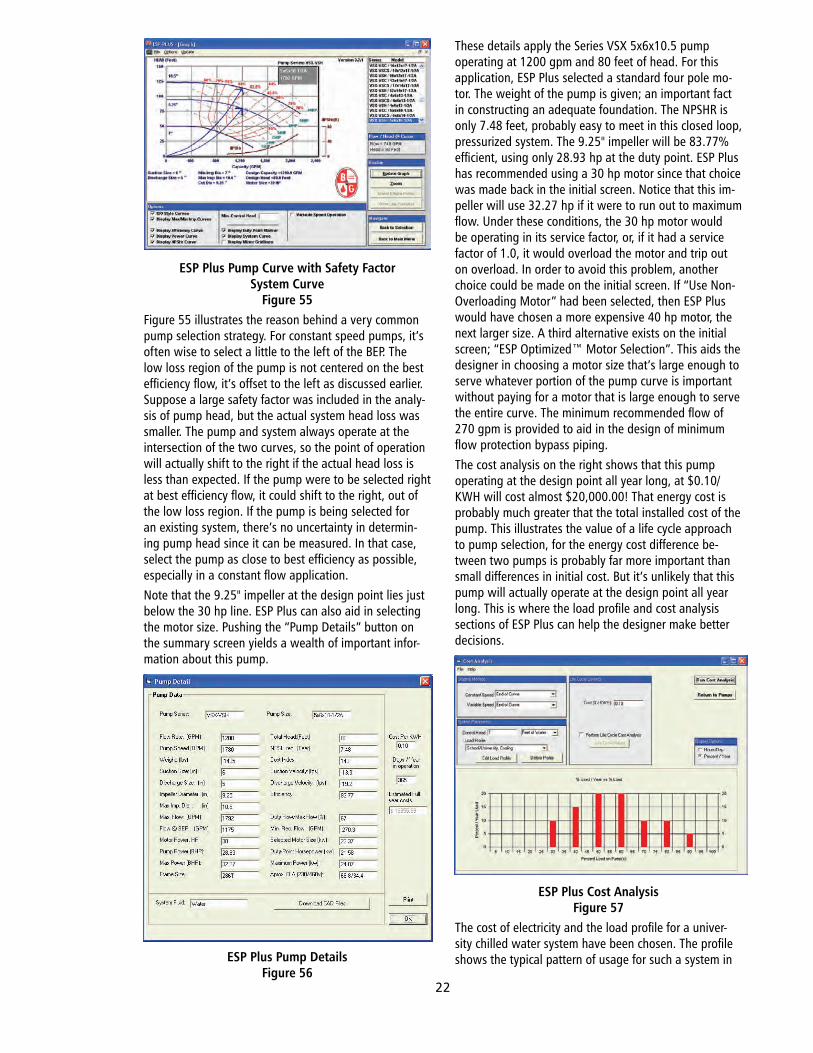
ESP Plus Pump Curve with Safety Factor System Curve
Figure 55Figure 55 illustrates the reason behind a very common pump selection strategy. For constant speed pumps, it’s often wise to select a little to the left of the BEP. The low loss region of the pump is not centered on the best efficiency flow, it’s offset to the left as discussed earlier. Suppose a large safety factor was included in the analy-sis of pump head, but the actual system head loss was smaller. The pump and system always operate at the intersection of the two curves, so the point of operation will actually shift to the right if the actual head loss is less than expected. If the pump were to be selected right at best efficiency flow, it could shift to the right, out of the low loss region. If the pump is being selected for an existing system, there’s no uncertainty in determin-ing pump head since it can be measured. In that case, select the pump as close to best efficiency as possible, especially in a constant flow application.Note that the 9.25" impeller at the design point lies just below the 30 hp line. ESP Plus can also aid in selecting the motor size. Pushing the “Pump Details” button on the summary screen yields a wealth of important infor-mation about this pump.
ESP Plus Pump DetailsFigure 56
These details apply the Series VSX 5x6x10.5 pump operating at 1200 gpm and 80 feet of head. For this application, ESP Plus selected a standard four pole mo-tor. The weight of the pump is given; an important fact in constructing an adequate foundation. The NPSHR is only 7.48 feet, probably easy to meet in this closed loop, pressurized system. The 9.25" impeller will be 83.77% efficient, using only 28.93 hp at the duty point. ESP Plus has recommended using a 30 hp motor since that choice was made back in the initial screen. Notice that this im-peller will use 32.27 hp if it were to run out to maximum flow. Under these conditions, the 30 hp motor would be operating in its service factor, or, if it had a service factor of 1.0, it would overload the motor and trip out on overload. In order to avoid this problem, another choice could be made on the initial screen. If “Use Non-Overloading Motor” had been selected, then ESP Plus would have chosen a more expensive 40 hp motor, the next larger size. A third alternative exists on the initial screen; “ESP Optimized™ Motor Selection”. This aids the designer in choosing a motor size that’s large enough to serve whatever portion of the pump curve is important without paying for a motor that is large enough to serve the entire curve. The minimum recommended flow of 270 gpm is provided to aid in the design of minimum flow protection bypass piping.The cost analysis on the right shows that this pump operating at the design point all year long, at $0.10/KWH will cost almost $20,000.00! That energy cost is probably much greater that the total installed cost of the pump. This illustrates the value of a life cycle approach to pump selection, for the energy cost difference be-tween two pumps is probably far more important than small differences in initial cost. But it’s unlikely that this pump will actually operate at the design point all year long. This is where the load profile and cost analysis sections of ESP Plus can help the designer make better decisions.
ESP Plus Cost AnalysisFigure 57
The cost of electricity and the load profile for a univer-sity chilled water system have been chosen. The profile shows the typical pattern of usage for such a system in
22
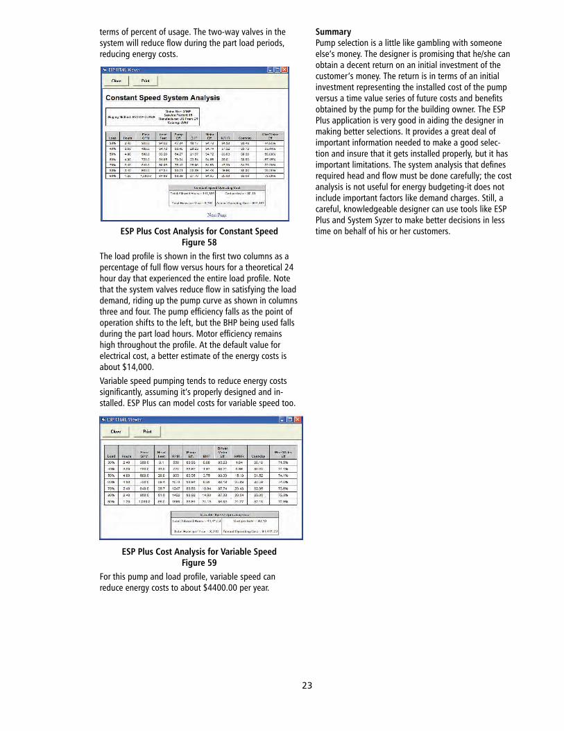
terms of percent of usage. The two-way valves in the system will reduce flow during the part load periods, reducing energy costs.
ESP Plus Cost Analysis for Constant SpeedFigure 58
The load profile is shown in the first two columns as a percentage of full flow versus hours for a theoretical 24 hour day that experienced the entire load profile. Note that the system valves reduce flow in satisfying the load demand, riding up the pump curve as shown in columns three and four. The pump efficiency falls as the point of operation shifts to the left, but the BHP being used falls during the part load hours. Motor efficiency remains high throughout the profile. At the default value for electrical cost, a better estimate of the energy costs is about $14,000.Variable speed pumping tends to reduce energy costs significantly, assuming it’s properly designed and in-stalled. ESP Plus can model costs for variable speed too.
ESP Plus Cost Analysis for Variable SpeedFigure 59
For this pump and load profile, variable speed can reduce energy costs to about $4400.00 per year.
SummaryPump selection is a little like gambling with someone else’s money. The designer is promising that he/she can obtain a decent return on an initial investment of the customer’s money. The return is in terms of an initial investment representing the installed cost of the pump versus a time value series of future costs and benefits obtained by the pump for the building owner. The ESP Plus application is very good in aiding the designer in making better selections. It provides a great deal of important information needed to make a good selec-tion and insure that it gets installed properly, but it has important limitations. The system analysis that defines required head and flow must be done carefully; the cost analysis is not useful for energy budgeting-it does not include important factors like demand charges. Still, a careful, knowledgeable designer can use tools like ESP Plus and System Syzer to make better decisions in less time on behalf of his or her customers.
23

NOTES

BULLETIN NO. TEH-1208
Pump Selection for Building Service Systems
Bell & Gossett®
© Copyright © 2010 ITT CorporationPrinted in U.S.A. 1-10
THE ITT ENGINEERED BLOCKS SYMBOL AND ENGINEERED FOR LIFE ARE REGISTERED TRADEMARKS OF ITT MANUFACTURING ENTERPRISES, INC.
ITT8200 N. Austin AvenueMorton Grove, IL 60053 Phone: (847) 966-3700Fax: (847) 966-9052www.bellgossett.com
ITT
07152A Cov.indd 2-3 1/21/10 1:50 PM


